JP4470771B2 - Control device for internal combustion engine - Google Patents
Control device for internal combustion engine Download PDFInfo
- Publication number
- JP4470771B2 JP4470771B2 JP2005078292A JP2005078292A JP4470771B2 JP 4470771 B2 JP4470771 B2 JP 4470771B2 JP 2005078292 A JP2005078292 A JP 2005078292A JP 2005078292 A JP2005078292 A JP 2005078292A JP 4470771 B2 JP4470771 B2 JP 4470771B2
- Authority
- JP
- Japan
- Prior art keywords
- fuel injection
- fuel
- engine
- internal combustion
- combustion engine
- Prior art date
- Legal status (The legal status is an assumption and is not a legal conclusion. Google has not performed a legal analysis and makes no representation as to the accuracy of the status listed.)
- Expired - Fee Related
Links
- 238000002485 combustion reaction Methods 0.000 title claims description 99
- 239000000446 fuel Substances 0.000 claims description 319
- 238000002347 injection Methods 0.000 claims description 200
- 239000007924 injection Substances 0.000 claims description 200
- 238000004880 explosion Methods 0.000 claims description 13
- 230000001052 transient effect Effects 0.000 description 16
- 239000000203 mixture Substances 0.000 description 13
- XLYOFNOQVPJJNP-UHFFFAOYSA-N water Substances O XLYOFNOQVPJJNP-UHFFFAOYSA-N 0.000 description 13
- 238000000034 method Methods 0.000 description 12
- 230000006835 compression Effects 0.000 description 10
- 238000007906 compression Methods 0.000 description 10
- 239000003054 catalyst Substances 0.000 description 9
- 230000008569 process Effects 0.000 description 9
- 239000000498 cooling water Substances 0.000 description 8
- 230000008859 change Effects 0.000 description 6
- 230000006870 function Effects 0.000 description 4
- 230000003197 catalytic effect Effects 0.000 description 3
- 238000010586 diagram Methods 0.000 description 3
- 239000002828 fuel tank Substances 0.000 description 3
- QVGXLLKOCUKJST-UHFFFAOYSA-N atomic oxygen Chemical compound [O] QVGXLLKOCUKJST-UHFFFAOYSA-N 0.000 description 2
- 230000002457 bidirectional effect Effects 0.000 description 2
- 239000002826 coolant Substances 0.000 description 2
- 238000001816 cooling Methods 0.000 description 2
- 230000003247 decreasing effect Effects 0.000 description 2
- 239000001301 oxygen Substances 0.000 description 2
- 229910052760 oxygen Inorganic materials 0.000 description 2
- 238000009834 vaporization Methods 0.000 description 2
- 230000008016 vaporization Effects 0.000 description 2
- 230000002159 abnormal effect Effects 0.000 description 1
- 238000009825 accumulation Methods 0.000 description 1
- 239000000567 combustion gas Substances 0.000 description 1
- 230000001186 cumulative effect Effects 0.000 description 1
- 230000000994 depressogenic effect Effects 0.000 description 1
- 230000000694 effects Effects 0.000 description 1
- 239000007789 gas Substances 0.000 description 1
- 239000003502 gasoline Substances 0.000 description 1
- 239000008240 homogeneous mixture Substances 0.000 description 1
- 230000006872 improvement Effects 0.000 description 1
- 238000004519 manufacturing process Methods 0.000 description 1
- 238000002156 mixing Methods 0.000 description 1
- 238000012986 modification Methods 0.000 description 1
- 230000004048 modification Effects 0.000 description 1
- ADTDNFFHPRZSOT-PVFUSPOPSA-N ram-330 Chemical compound C([C@H]1N(CC2)C)C3=CC=C(OC)C(OC)=C3[C@]32[C@@]1(O)CC[C@@H](OC(=O)OCC)C3 ADTDNFFHPRZSOT-PVFUSPOPSA-N 0.000 description 1
- 238000005507 spraying Methods 0.000 description 1
- 230000000087 stabilizing effect Effects 0.000 description 1
- 230000007704 transition Effects 0.000 description 1
- 238000011144 upstream manufacturing Methods 0.000 description 1
- 238000010792 warming Methods 0.000 description 1
Images


Classifications
-
- F—MECHANICAL ENGINEERING; LIGHTING; HEATING; WEAPONS; BLASTING
- F02—COMBUSTION ENGINES; HOT-GAS OR COMBUSTION-PRODUCT ENGINE PLANTS
- F02D—CONTROLLING COMBUSTION ENGINES
- F02D41/00—Electrical control of supply of combustible mixture or its constituents
- F02D41/02—Circuit arrangements for generating control signals
- F02D41/04—Introducing corrections for particular operating conditions
- F02D41/06—Introducing corrections for particular operating conditions for engine starting or warming up
- F02D41/062—Introducing corrections for particular operating conditions for engine starting or warming up for starting
-
- F—MECHANICAL ENGINEERING; LIGHTING; HEATING; WEAPONS; BLASTING
- F02—COMBUSTION ENGINES; HOT-GAS OR COMBUSTION-PRODUCT ENGINE PLANTS
- F02D—CONTROLLING COMBUSTION ENGINES
- F02D41/00—Electrical control of supply of combustible mixture or its constituents
- F02D41/02—Circuit arrangements for generating control signals
- F02D41/04—Introducing corrections for particular operating conditions
- F02D41/06—Introducing corrections for particular operating conditions for engine starting or warming up
- F02D41/068—Introducing corrections for particular operating conditions for engine starting or warming up for warming-up
-
- F—MECHANICAL ENGINEERING; LIGHTING; HEATING; WEAPONS; BLASTING
- F02—COMBUSTION ENGINES; HOT-GAS OR COMBUSTION-PRODUCT ENGINE PLANTS
- F02D—CONTROLLING COMBUSTION ENGINES
- F02D41/00—Electrical control of supply of combustible mixture or its constituents
- F02D41/24—Electrical control of supply of combustible mixture or its constituents characterised by the use of digital means
- F02D41/2406—Electrical control of supply of combustible mixture or its constituents characterised by the use of digital means using essentially read only memories
- F02D41/2425—Particular ways of programming the data
- F02D41/2429—Methods of calibrating or learning
- F02D41/2441—Methods of calibrating or learning characterised by the learning conditions
- F02D41/2445—Methods of calibrating or learning characterised by the learning conditions characterised by a plurality of learning conditions or ranges
-
- F—MECHANICAL ENGINEERING; LIGHTING; HEATING; WEAPONS; BLASTING
- F02—COMBUSTION ENGINES; HOT-GAS OR COMBUSTION-PRODUCT ENGINE PLANTS
- F02D—CONTROLLING COMBUSTION ENGINES
- F02D41/00—Electrical control of supply of combustible mixture or its constituents
- F02D41/24—Electrical control of supply of combustible mixture or its constituents characterised by the use of digital means
- F02D41/2406—Electrical control of supply of combustible mixture or its constituents characterised by the use of digital means using essentially read only memories
- F02D41/2425—Particular ways of programming the data
- F02D41/2429—Methods of calibrating or learning
- F02D41/2441—Methods of calibrating or learning characterised by the learning conditions
- F02D41/2448—Prohibition of learning
-
- F—MECHANICAL ENGINEERING; LIGHTING; HEATING; WEAPONS; BLASTING
- F02—COMBUSTION ENGINES; HOT-GAS OR COMBUSTION-PRODUCT ENGINE PLANTS
- F02D—CONTROLLING COMBUSTION ENGINES
- F02D41/00—Electrical control of supply of combustible mixture or its constituents
- F02D41/24—Electrical control of supply of combustible mixture or its constituents characterised by the use of digital means
- F02D41/2406—Electrical control of supply of combustible mixture or its constituents characterised by the use of digital means using essentially read only memories
- F02D41/2425—Particular ways of programming the data
- F02D41/2429—Methods of calibrating or learning
- F02D41/2451—Methods of calibrating or learning characterised by what is learned or calibrated
- F02D41/2454—Learning of the air-fuel ratio control
-
- F—MECHANICAL ENGINEERING; LIGHTING; HEATING; WEAPONS; BLASTING
- F02—COMBUSTION ENGINES; HOT-GAS OR COMBUSTION-PRODUCT ENGINE PLANTS
- F02D—CONTROLLING COMBUSTION ENGINES
- F02D41/00—Electrical control of supply of combustible mixture or its constituents
- F02D41/30—Controlling fuel injection
- F02D41/3094—Controlling fuel injection the fuel injection being effected by at least two different injectors, e.g. one in the intake manifold and one in the cylinder
Description
本発明は、筒内に向けて燃料を噴射する第1の燃料噴射手段(筒内噴射用インジェクタ)と吸気通路または吸気ポート内に向けて燃料を噴射する第2の燃料噴射手段(吸気通路噴射用インジェクタ)とを備えた内燃機関の制御装置に関し、特に、第1の燃料噴射手段および第2の燃料噴射手段からの燃料噴射量を補正する技術に関する。 The present invention provides first fuel injection means (in-cylinder injector) for injecting fuel into the cylinder and second fuel injection means (intake passage injection) for injecting fuel into the intake passage or intake port. In particular, the present invention relates to a technique for correcting the amount of fuel injection from the first fuel injection means and the second fuel injection means.
機関吸気通路内に燃料を噴射するための吸気通路噴射用インジェクタと、機関燃焼室内に常時燃料を噴射するための筒内噴射用インジェクタとを具備し、機関負荷が予め定められた設定負荷よりも低いときには吸気通路噴射用インジェクタからの燃料噴射を停止すると共に機関負荷が設定負荷よりも高いときには吸気通路噴射用インジェクタから燃料を噴射するようにした内燃機関が公知である。 An injector for injecting intake passage for injecting fuel into the engine intake passage and an in-cylinder injector for injecting fuel at all times into the engine combustion chamber, the engine load being higher than a predetermined set load There is known an internal combustion engine that stops fuel injection from the intake passage injector when the engine load is low and injects fuel from the intake passage injector when the engine load is higher than the set load.
このような内燃機関においても、インジェクタに堆積するデポジットや製造時の個体差により、燃料噴射量が所望の噴射量とならない場合がある。すなわち、空燃比が所望の空燃比(たとえば理論空燃比)からずれる場合がある。この燃料噴射量のずれを補正するため、1気筒に対し1つのインジェクタが設けられた内燃機関と同様に、空燃比のフィードバック制御により、燃料噴射量が補正される。 Even in such an internal combustion engine, the fuel injection amount may not be a desired injection amount due to deposits accumulated in the injector and individual differences during manufacture. That is, the air-fuel ratio may deviate from a desired air-fuel ratio (for example, the theoretical air-fuel ratio). In order to correct the deviation of the fuel injection amount, the fuel injection amount is corrected by feedback control of the air-fuel ratio, similarly to the internal combustion engine in which one injector is provided for one cylinder.
特開平3−185242号公報(特許文献1)は、1気筒あたり複数個の燃料噴射弁を備えた内燃機関において、燃料噴射量を精度よく補正する内燃機関の燃料噴射量制御装置を開示する。この燃料噴射量制御装置は、運転状態に応じて複数の燃料噴射弁からの燃料噴射を制御する制御部と、機関の排気系に設けられた酸素センサからの出力信号に基づく値を学習して燃料噴射量を補正する学習部と、複数個の燃料噴射弁の使用状態に対応して複数の学習領域を設定する設定部と、学習領域の夫々において学習した各学習値を使用して各学習領域に対応する運転状態時に、燃料噴射量を補正する補正部とを含む。 Japanese Patent Laying-Open No. 3-185242 (Patent Document 1) discloses a fuel injection amount control device for an internal combustion engine that accurately corrects the fuel injection amount in an internal combustion engine having a plurality of fuel injection valves per cylinder. This fuel injection amount control device learns a value based on an output signal from a control unit that controls fuel injection from a plurality of fuel injection valves according to an operating state and an oxygen sensor provided in an exhaust system of the engine. Each learning using a learning unit for correcting the fuel injection amount, a setting unit for setting a plurality of learning regions corresponding to the use states of the plurality of fuel injection valves, and each learning value learned in each of the learning regions And a correction unit that corrects the fuel injection amount in the operation state corresponding to the region.
この公報に記載の燃料噴射量制御装置によれば、学習領域で使用されている燃料噴射弁と、学習値を用いて燃料噴射量を補正するときの使用噴射弁が一致する。そのため、燃料噴射量の補正精度が向上する。したがって、これに伴い空燃比の追従性が向上し、排気エミッションが改善される。また目標空燃比からの誤差が小さくなるため空燃比をリーン側に設定しても失火の可能性を少なくして燃費を向上することができる。
ところで、内燃機関においては、たとえば冷間始動時において、始動性などの向上のため、燃料噴射量を増量したりする。このように燃料噴射量を増量している場合は、燃料噴射量を増量していない場合に比べて必然的に空燃比が変化し得る。しかしながら、特開平3−185242号公報に記載の燃料噴射量制御装置においては、燃料噴射量を増量している場合については考慮されていない。したがって、学習値の学習により、不必要に燃料噴射量が補正されるおそれがあり、学習値に基づく燃料噴射量の補正が不適切な場合が生じ得る。 By the way, in an internal combustion engine, for example, at the time of cold start, the fuel injection amount is increased in order to improve startability and the like. When the fuel injection amount is increased in this way, the air-fuel ratio can inevitably change compared to the case where the fuel injection amount is not increased. However, in the fuel injection amount control device described in Japanese Patent Laid-Open No. 3-185242, the case where the fuel injection amount is increased is not taken into consideration. Therefore, there is a possibility that the fuel injection amount may be unnecessarily corrected by learning the learning value, and there may occur a case where the correction of the fuel injection amount based on the learning value is inappropriate.
本発明は、上述の問題点を解決するためになされたものであって、その目的は、燃料噴射量を適切に補正することができる内燃機関の制御装置を提供することである。 The present invention has been made to solve the above-described problems, and an object thereof is to provide a control device for an internal combustion engine that can appropriately correct the fuel injection amount.
第1の発明に係る内燃機関の制御装置においては、筒内に燃料を噴射するための第1の燃料噴射手段と吸気通路内に燃料を噴射するための第2の燃料噴射手段とを備えた内燃機関を制御する。この制御装置は、少なくとも内燃機関の温度が予め定められた値以下のクランキング時およびアイドル時において、第1の燃料噴射手段および第2の燃料噴射手段のいずれか一方のみから燃料が噴射されるように、燃料噴射手段を制御するための第1の制御手段と、第1の燃料噴射手段および第2の燃料噴射手段から燃料が噴射されるように、燃料噴射手段を制御するための第2の制御手段と、空燃比に基づいて燃料噴射量の補正値を算出するための算出手段と、少なくとも内燃機関のクランキング開始時から完爆するまでの期間において、燃料噴射量の補正値の算出を禁止するための禁止手段と、内燃機関の完爆後の予め定められた期間において、燃料噴射量の補正値の算出を許可するための許可手段とを含む。 The control apparatus for an internal combustion engine according to the first invention includes a first fuel injection means for injecting fuel into the cylinder and a second fuel injection means for injecting fuel into the intake passage. Control the internal combustion engine. This control device injects fuel from only one of the first fuel injection means and the second fuel injection means at least during cranking and idling when the temperature of the internal combustion engine is equal to or lower than a predetermined value. As described above, the first control means for controlling the fuel injection means, and the second for controlling the fuel injection means so that the fuel is injected from the first fuel injection means and the second fuel injection means. Control means, a calculation means for calculating a correction value of the fuel injection amount based on the air-fuel ratio, and calculation of a correction value of the fuel injection amount at least during the period from the start of cranking of the internal combustion engine to the complete explosion And a permission means for permitting calculation of the correction value of the fuel injection amount in a predetermined period after the complete explosion of the internal combustion engine.
第1の発明によると、第1の制御手段は、少なくとも内燃機関の温度が予め定められた値以下のクランキング時およびアイドル時において、第1の燃料噴射手段および第2の燃料噴射手段のいずれか一方のみから燃料が噴射されるように、燃料噴射手段を制御する。第2の制御手段は、第1の燃料噴射手段および第2の燃料噴射手段から燃料が噴射されるように、燃料噴射手段を制御する。このように燃料噴射手段が制御される内燃機関においは、第1の燃料噴射手段および第2の燃料噴射手段のいずれか一方のみから燃料が噴射される機会が多いとは限らない。したがって、第1の燃料噴射手段および第2の燃料噴射手段のいずれか一方のみから燃料が噴射される状態における燃料噴射量の補正値を算出する機会が多いとは限らない。そのため、第1の燃料噴射手段および第2の燃料噴射手段のいずれか一方のみから燃料が噴射される状態においては、できるだけ燃料噴射量の補正値を算出する必要がある。よって、第1の燃料噴射手段および第2の燃料噴射手段のいずれか一方のみから燃料が噴射され得る(内燃機関の温度が予め定められた値以下のクランキング時およびアイドル時が含まれ得る)内燃機関の冷間時においても補正値を算出することが考えられる。ところで内燃機関の冷間時における始動の際には、少なくともクランキング開始時から完爆するまでの期間において、過渡的に燃料噴射量が補正(増量)されたりする。また、完爆後の予め定められた期間において、内燃機関の温度に応じて定常的に燃料噴射量が補正(増量)されたりする。過渡的に噴射量が増量されている場合は、空燃比が急変するおそれがある。一方、定常的に噴射量が増量されている場合は、空燃比が安定する。したがって、少なくともクランキング開始時から、完爆するまでの期間において、燃料噴射量の補正値の算出が禁止される。完爆後の予め定められた期間において、燃料噴射量の補正値の算出が許可される。これにより、空燃比が安定している状態において燃料噴射量の補正値を算出することができる。そのため、補正値の誤算出を抑制することができる。その結果、燃料噴射量を適切に補正することができる内燃機関の制御装置を提供することができる。 According to the first invention, the first control means is one of the first fuel injection means and the second fuel injection means at least during cranking and idling when the temperature of the internal combustion engine is equal to or lower than a predetermined value. The fuel injection means is controlled so that the fuel is injected from only one of them. The second control means controls the fuel injection means so that fuel is injected from the first fuel injection means and the second fuel injection means. In an internal combustion engine in which the fuel injection means is controlled in this way, there are not always many opportunities for fuel to be injected from only one of the first fuel injection means and the second fuel injection means. Therefore, there are not always many opportunities to calculate the correction value of the fuel injection amount in the state where the fuel is injected from only one of the first fuel injection unit and the second fuel injection unit. Therefore, in a state where fuel is injected from only one of the first fuel injection unit and the second fuel injection unit, it is necessary to calculate a correction value for the fuel injection amount as much as possible. Therefore, the fuel can be injected from only one of the first fuel injection means and the second fuel injection means (cranking time and idling time when the temperature of the internal combustion engine is not more than a predetermined value can be included). It is conceivable to calculate the correction value even when the internal combustion engine is cold. By the way, when the internal combustion engine is started when it is cold, the fuel injection amount is transiently corrected (increased) at least during the period from the start of cranking to the complete explosion. Further, during a predetermined period after the complete explosion, the fuel injection amount is constantly corrected (increased) according to the temperature of the internal combustion engine. When the injection amount is increased transiently, the air-fuel ratio may change suddenly. On the other hand, when the injection amount is constantly increased, the air-fuel ratio is stabilized. Therefore, calculation of the fuel injection amount correction value is prohibited at least during the period from the start of cranking to the complete explosion. Calculation of the correction value of the fuel injection amount is permitted in a predetermined period after the complete explosion. Thereby, the correction value of the fuel injection amount can be calculated in a state where the air-fuel ratio is stable. Therefore, erroneous calculation of the correction value can be suppressed. As a result, it is possible to provide a control device for an internal combustion engine that can appropriately correct the fuel injection amount.
第2の発明に係る内燃機関の制御装置においては、第1の発明の構成に加え、第1の制御手段は、内燃機関の温度が予め定められた値以下のクランキング時およびアイドル時において、第2の燃料噴射手段のみから燃料が噴射されるように、燃料噴射手段を制御するための手段を含む。 In the control device for an internal combustion engine according to the second invention, in addition to the configuration of the first invention, the first control means is configured to perform the cranking and idling when the temperature of the internal combustion engine is equal to or lower than a predetermined value. Means for controlling the fuel injection means are included so that fuel is injected only from the second fuel injection means.
第2の発明によると、内燃機関の温度が予め定められた値以下のクランキング時およびアイドル時において、第2の燃料噴射手段のみから燃料が噴射されるように、燃料噴射手段が制御される。このように燃料噴射手段が制御される内燃機関においては、第2の燃料噴射手段のみから燃料が噴射される機会が多いとは限らない。したがって、第2の燃料噴射手段のみから燃料が噴射される状態における燃料噴射量の補正値を算出する機会が多いとは限らない。そのため、第2の燃料噴射手段のみから燃料が噴射される状態においては、できるだけ燃料噴射量の補正値を算出する必要がある。よって、第2の燃料噴射手段のみから燃料が噴射され得る(内燃機関の温度が予め定められた値以下のクランキング時およびアイドル時が含まれ得る)内燃機関の冷間時においても補正値を算出することが考えられる。ところで内燃機関の冷間時における始動の際には、少なくともクランキング開始時から完爆するまでの期間において、過渡的に燃料噴射量が補正(増量)されたりする。また、完爆後の予め定められた期間において、内燃機関の温度に応じて定常的に燃料噴射量が補正(増量)されたりする。過渡的に噴射量が増量されている場合は、空燃比が急変するおそれがある。一方、定常的に噴射量が増量されている場合は、空燃比が安定する。したがって、少なくともクランキング開始時から、完爆するまでの期間において、燃料噴射量の補正値の算出が禁止される。完爆後の予め定められた期間において、燃料噴射量の補正値の算出が許可される。これにより、空燃比が安定している状態において燃料噴射量の補正値を算出することができる。そのため、補正値の誤算出を抑制することができる。 According to the second invention, the fuel injection means is controlled so that the fuel is injected only from the second fuel injection means at the time of cranking and idling when the temperature of the internal combustion engine is not more than a predetermined value. . In the internal combustion engine in which the fuel injection means is controlled in this way, there are not always many opportunities for fuel to be injected only from the second fuel injection means. Therefore, there are not always many opportunities to calculate the correction value of the fuel injection amount in the state where the fuel is injected only from the second fuel injection means. Therefore, in a state where fuel is injected only from the second fuel injection means, it is necessary to calculate a correction value for the fuel injection amount as much as possible. Therefore, the correction value can be set even when the internal combustion engine is cold, in which fuel can be injected only from the second fuel injection means (the temperature of the internal combustion engine can be cranking or idling when the temperature is lower than a predetermined value). It is conceivable to calculate. By the way, when the internal combustion engine is started when it is cold, the fuel injection amount is transiently corrected (increased) at least during the period from the start of cranking to the complete explosion. Further, during a predetermined period after the complete explosion, the fuel injection amount is constantly corrected (increased) according to the temperature of the internal combustion engine. When the injection amount is increased transiently, the air-fuel ratio may change suddenly. On the other hand, when the injection amount is constantly increased, the air-fuel ratio is stabilized. Therefore, calculation of the fuel injection amount correction value is prohibited at least during the period from the start of cranking to the complete explosion. Calculation of the correction value of the fuel injection amount is permitted in a predetermined period after the complete explosion. Thereby, the correction value of the fuel injection amount can be calculated in a state where the air-fuel ratio is stable. Therefore, erroneous calculation of the correction value can be suppressed.
第3の発明に係る内燃機関の制御装置においては、第1または2の発明の構成に加え、予め定められた期間は、内燃機関の温度に基づいて燃料噴射量が補正される期間である。 In the control apparatus for an internal combustion engine according to the third invention, in addition to the configuration of the first or second invention, the predetermined period is a period in which the fuel injection amount is corrected based on the temperature of the internal combustion engine.
第3の発明によると、内燃機関の温度に応じて定常的に燃料噴射量が補正されている場合は、空燃比が安定する。このような期間において、燃料噴射量の補正値の算出が許可される。これにより、空燃比が安定している状態において燃料噴射量の補正値を算出することができる。そのため、補正値の誤算出を抑制することができる。 According to the third invention, the air-fuel ratio is stabilized when the fuel injection amount is constantly corrected in accordance with the temperature of the internal combustion engine. During such a period, calculation of the fuel injection amount correction value is permitted. Thereby, the correction value of the fuel injection amount can be calculated in a state where the air-fuel ratio is stable. Therefore, erroneous calculation of the correction value can be suppressed.
第4の発明に係る内燃機関の制御装置は、第3の発明の構成に加え、内燃機関の温度および空燃比以外に基づいて燃料噴射量が補正された場合において算出された補正値に基づく燃料噴射量の補正を禁止するための手段をさらに含む。 The control apparatus for an internal combustion engine according to a fourth aspect of the invention includes a fuel based on a correction value calculated when the fuel injection amount is corrected on the basis of other than the temperature and air-fuel ratio of the internal combustion engine in addition to the configuration of the third aspect of the invention. Means for prohibiting correction of the injection amount is further included.
第4の発明によると、内燃機関の温度および空燃比以外(たとえば、吸気ポートの壁面に付着した燃料やキャニスタからパージされる燃料)に基づいて燃料噴射量が補正された場合において算出された補正値に基づく燃料噴射量の補正が禁止される。これにより、吸気ポートの壁面に付着した燃料やキャニスタからパージされる燃料に基づいて、過渡的に燃料噴射量が補正された場合において算出された補正値により、不必要に燃料噴射量が補正されることを抑制することができる。そのため、燃料噴射量を適切に補正することができる。 According to the fourth aspect of the invention, the correction calculated when the fuel injection amount is corrected based on other than the temperature and air-fuel ratio of the internal combustion engine (for example, fuel adhering to the wall surface of the intake port or fuel purged from the canister). Correction of the fuel injection amount based on the value is prohibited. As a result, the fuel injection amount is unnecessarily corrected by the correction value calculated when the fuel injection amount is transiently corrected based on the fuel adhering to the wall surface of the intake port or the fuel purged from the canister. Can be suppressed. Therefore, the fuel injection amount can be corrected appropriately.
第5の発明に係る内燃機関の制御装置においては、第1〜4のいずれかの発明の構成に加え、第1の燃料噴射手段は、筒内噴射用インジェクタである。第2の燃料噴射手段は、吸気通路用インジェクタである。 In the control apparatus for an internal combustion engine according to the fifth invention, in addition to the configuration of any one of the first to fourth inventions, the first fuel injection means is an in-cylinder injector. The second fuel injection means is an intake passage injector.
第5の発明によると、第1の燃料噴射手段である筒内噴射用インジェクタと第2の燃料噴射手段である吸気通路噴射用インジェクタとを別個に設けて噴射燃料を分担する内燃機関において、適切に燃料噴射量を補正することができる。 According to the fifth aspect of the present invention, in the internal combustion engine that shares the injected fuel by separately providing the in-cylinder injector that is the first fuel injection means and the intake passage injection injector that is the second fuel injection means, It is possible to correct the fuel injection amount.
以下、図面を参照しつつ、本発明の実施の形態について説明する。以下の説明では、同一の部品には同一の符号を付してある。それらの名称および機能も同一である。したがって、それらについての詳細な説明は繰返さない。 Hereinafter, embodiments of the present invention will be described with reference to the drawings. In the following description, the same parts are denoted by the same reference numerals. Their names and functions are also the same. Therefore, detailed description thereof will not be repeated.
<第1の実施の形態>
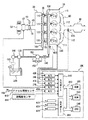
図1に、本発明の第1の実施の形態に係る内燃機関の制御装置であるエンジンECU(Electronic Control Unit)で制御されるエンジンシステムの概略構成図を示す。なお、図1には、エンジンとして直列4気筒ガソリンエンジンを示すが、本発明はこのようなエンジンに限定されるものではなく、V型6気筒エンジン、V型8気筒エンジンなど、種々の形式のエンジンに適用可能である。
<First Embodiment>
FIG. 1 shows a schematic configuration diagram of an engine system controlled by an engine ECU (Electronic Control Unit) which is a control device for an internal combustion engine according to a first embodiment of the present invention. Although FIG. 1 shows an in-line four-cylinder gasoline engine as an engine, the present invention is not limited to such an engine, and various types of engines such as a V-type 6-cylinder engine and a V-type 8-cylinder engine can be used. Applicable to engine.
図1に示すように、エンジン10は、4つの気筒112を備え、各気筒112はそれぞれ対応するインテークマニホールド20を介して共通のサージタンク30に接続されている。サージタンク30は、吸気ダクト40を介してエアクリーナ50に接続され、吸気ダクト40内にはエアフローメータ42が配置されるとともに、電動モータ60によって駆動されるスロットルバルブ70が配置されている。このスロットルバルブ70は、アクセルペダル100とは独立してエンジンECU300の出力信号に基づいてその開度が制御される。一方、各気筒112は共通のエキゾーストマニホールド80に連結され、このエキゾーストマニホールド80は三元触媒コンバータ90に連結されている。
As shown in FIG. 1, the
各気筒112に対しては、筒内に向けて燃料を噴射するための筒内噴射用インジェクタ110と、吸気ポートまたは/および吸気通路内に向けて燃料を噴射するための吸気通路噴射用インジェクタ120とがそれぞれ設けられている。これらインジェクタ110、120はエンジンECU300の出力信号に基づいてそれぞれ制御される。また、各気筒内噴射用インジェクタ110は共通の燃料分配管130に接続されており、この燃料分配管130は燃料分配管130に向けて流通可能な逆止弁140を介して、機関駆動式の高圧燃料ポンプ150に接続されている。なお、本実施の形態においては、2つのインジェクタが別個に設けられた内燃機関について説明するが、本発明はこのような内燃機関に限定されない。たとえば、筒内噴射機能と吸気通路噴射機能とを併せ持つような1個のインジェクタを有する内燃機関であってもよい。
For each
図1に示すように、高圧燃料ポンプ150の吐出側は電磁スピル弁152を介して高圧燃料ポンプ150の吸入側に連結されており、この電磁スピル弁152の開度が小さいときほど、高圧燃料ポンプ150から燃料分配管130内に供給される燃料量が増大され、電磁スピル弁152が全開にされると、高圧燃料ポンプ150から燃料分配管130への燃料供給が停止されるように構成されている。なお、電磁スピル弁152はエンジンECU300の出力信号に基づいて制御される。
As shown in FIG. 1, the discharge side of the high-
一方、各吸気通路噴射用インジェクタ120は、共通する低圧側の燃料分配管160に接続されており、燃料分配管160および高圧燃料ポンプ150は共通の燃料圧レギュレータ170を介して、電動モータ駆動式の低圧燃料ポンプ180に接続されている。さらに、低圧燃料ポンプ180は燃料フィルタ190を介して燃料タンク200に接続されている。燃料圧レギュレータ170は低圧燃料ポンプ180から吐出された燃料の燃料圧が予め定められた設定燃料圧よりも高くなると、低圧燃料ポンプ180から吐出された燃料の一部を燃料タンク200に戻すように構成されており、したがって吸気通路噴射用インジェクタ120に供給されている燃料圧および高圧燃料ポンプ150に供給されている燃料圧が上記設定燃料圧よりも高くなるのを阻止している。
On the other hand, each
エンジンECU300は、デジタルコンピュータから構成され、双方向性バス310を介して相互に接続されたROM(Read Only Memory)320、RAM(Random Access Memory)330、CPU(Central Processing Unit)340、入力ポート350および出力ポート360を備えている。
The
エアフローメータ42は吸入空気量に比例した出力電圧を発生し、このエアフローメータ42の出力電圧はA/D変換器370を介して入力ポート350に入力される。エンジン10には機関冷却水温に比例した出力電圧を発生する水温センサ380が取付けられ、この水温センサ380の出力電圧は、A/D変換器390を介して入力ポート350に入力される。
The
燃料分配管130には燃料分配管130内の燃料圧に比例した出力電圧を発生する燃料圧センサ400が取付けられ、この燃料圧センサ400の出力電圧は、A/D変換器410を介して入力ポート350に入力される。三元触媒コンバータ90上流のエキゾーストマニホールド80には、排気ガス中の酸素濃度に比例した出力電圧を発生する空燃比センサ420が取付けられ、この空燃比センサ420の出力電圧は、A/D変換器430を介して入力ポート350に入力される。
A
本実施の形態に係るエンジンシステムにおける空燃比センサ420は、エンジン10で燃焼された混合気の空燃比に比例した出力電圧を発生する全域空燃比センサ(リニア空燃比センサ)である。なお、空燃比センサ420としては、エンジン10で燃焼された混合気の空燃比が理論空燃比に対してリッチであるかリーンであるかをオン−オフ的に検出するO2センサを用いてもよい。
The air-
本実施の形態において、エンジンECU300は、空燃比センサ420の出力電圧に基づいて、燃料の総噴射量のフィードバック補正量を算出する。また、予め定められた学習条件が成立した場合、フィードバック補正量の学習値(燃料噴射量の恒常的なズレ量を表す値)を算出する。フィードバック補正量およびその学習値の算出は、吸入空気量をパラメータとして予め定められた学習領域内において行なわれる。学習領域については後で詳述する。
In the present embodiment,
なお、フィードバック補正量およびその学習値を算出する方法については、1気筒あたり1つのインジェクタが設けられた内燃機関において一般的に用いられている技術を利用すればよいため、ここではその詳細な説明は繰り返さない。 The feedback correction amount and the method for calculating the learning value thereof may be a technique generally used in an internal combustion engine provided with one injector per cylinder, and will be described in detail here. Will not repeat.
アクセルペダル100は、アクセルペダル100の踏込み量に比例した出力電圧を発生するアクセル開度センサ440に接続され、アクセル開度センサ440の出力電圧は、A/D変換器450を介して入力ポート350に入力される。また、入力ポート350には、機関回転数を表わす出力パルスを発生する回転数センサ460が接続されている。エンジンECU300のROM320には、上述のアクセル開度センサ440および回転数センサ460により得られる機関負荷率および機関回転数に基づき、運転状態に対応させて設定されている燃料噴射量の値や機関冷却水温に基づく補正値などが予めマップ化されて記憶されている。
The
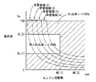
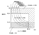
図2および図3を参照して、エンジン10の運転状態に対応させた情報である、筒内噴射用インジェクタ110と吸気通路噴射用インジェクタ120との噴き分け比率(以下、DI比率(r)とも記載する。)を表わすマップについて説明する。これらのマップは、エンジンECU300のROM320に記憶される。図2は、エンジン10の温間用マップであって、図3は、エンジン10の冷間用マップである。
Referring to FIGS. 2 and 3, the injection ratio of in-
図2および図3に示すように、これらのマップは、エンジン10の回転数を横軸にして、負荷率を縦軸にして、筒内噴射用インジェクタ110の分担比率がDI比率rとして百分率で示されている。
As shown in FIG. 2 and FIG. 3, these maps are expressed in percentages where the
図2および図3に示すように、エンジン10の回転数と負荷率とに定まる運転領域ごとに、DI比率rが設定されている。「DI比率r=100%」とは、筒内噴射用インジェクタ110からのみ燃料噴射が行なわれる領域であることを意味し、「DI比率r=0%」とは、吸気通路噴射用インジェクタ120からのみ燃料噴射が行なわれる領域であることを意味する。「DI比率r≠0%」、「DI比率r≠100%」および「0%<DI比率r<100%」とは、筒内噴射用インジェクタ110と吸気通路噴射用インジェクタ120とで燃料噴射が分担して行なわれる領域であることを意味する。なお、概略的には、筒内噴射用インジェクタ110は、出力性能の上昇に寄与し、吸気通路噴射用インジェクタ120は、混合気の均一性に寄与する。このような特性の異なる2種類のインジェクタを、エンジン10の回転数と負荷率とで使い分けることにより、エンジン10が通常運転状態(たとえば、アイドル時の触媒暖気時が、通常運転状態以外の非通常運転状態の一例であるといえる)である場合には、均質燃焼のみが行なわれるようにしている。
As shown in FIGS. 2 and 3, the DI ratio r is set for each operation region determined by the rotation speed and load factor of the
さらに、これらの図2および図3に示すように、温間時のマップと冷間時のマップとに分けて、筒内噴射用インジェクタ110と吸気通路噴射用インジェクタ120のDI分担率rを規定した。エンジン10の温度が異なると、筒内噴射用インジェクタ110および吸気通路噴射用インジェクタ120の制御領域が異なるように設定されたマップを用いて、エンジン10の温度を検知して、エンジン10の温度が予め定められた温度しきい値以上であると図2の温間時のマップを選択して、そうではないと図3に示す冷間時のマップを選択する。それぞれ選択されたマップに基づいて、エンジン10の回転数と負荷率とに基づいて、筒内噴射用インジェクタ110および/または吸気通路噴射用インジェクタ120を制御する。
Further, as shown in FIG. 2 and FIG. 3, the DI share ratio r of the in-
本実施の形態においては、燃料の総噴射量が所望の噴射量になるように、DI比率rに基づいて、筒内噴射用インジェクタ110からの燃料噴射量および吸気通路噴射用インジェクタ120からの燃料噴射量が決定される。
In the present embodiment, the fuel injection amount from in-
図2および図3に設定されるエンジン10の回転数と負荷率について説明する。図2のNE(1)は2500〜2700rpmに設定され、KL(1)は30〜50%、KL(2)は60〜90%に設定されている。また、図3のNE(3)は2900〜3100rpmに設定されている。すなわち、NE(1)<NE(3)である。その他、図2のNE(2)や、図3のKL(3)、KL(4)も適宜設定されている。
The engine speed and load factor of
図2および図3を比較すると、図2に示す温間用マップのNE(1)よりも図3に示す冷間用マップのNE(3)の方が高い。これは、エンジン10の温度が低いほど、吸気通路噴射用インジェクタ120の制御領域が高いエンジン回転数の領域まで拡大されるということを示す。すなわち、エンジン10が冷えている状態であるので、(たとえ、筒内噴射用インジェクタ110から燃料を噴射しなくても)筒内噴射用インジェクタ110の噴口にデポジットが堆積しにくい。このため、吸気通路噴射用インジェクタ120を使って燃料を噴射する領域を拡大するように設定され、均質性を向上させることができる。
When FIG. 2 and FIG. 3 are compared, NE (3) of the map for cold shown in FIG. 3 is higher than NE (1) of the map for warm shown in FIG. This indicates that as the temperature of the
図2および図3を比較すると、エンジン10の回転数が、温間用マップにおいてはNE(1)以上の領域において、冷間用マップにおいてはNE(3)以上の領域において、「DI比率r=100%」である。また、負荷率が、温間用マップにおいてはKL(2)以上の領域において、冷間用マップにおいてはKL(4)以上の領域において、「DI比率r=100%」である。これは、予め定められた高エンジン回転数領域では筒内噴射用インジェクタ110のみが使用されること、予め定められた高エンジン負荷領域では筒内噴射用インジェクタ110のみが使用されるということを示す。すなわち、高回転領域や高負荷領域においては、筒内噴射用インジェクタ110のみで燃料を噴射しても、エンジン10の回転数や負荷が高く吸気量が多いので筒内噴射用インジェクタ110のみでも混合気を均質化しやすいためである。このようにすると、筒内噴射用インジェクタ110から噴射された燃料は燃焼室内で気化潜熱を伴い(燃焼室から熱を奪い)気化される。これにより、圧縮端での混合気の温度が下がる。これにより対ノッキング性能が向上する。また、燃焼室の温度が下がるので、吸入効率が向上し高出力が見込める。
Comparing FIG. 2 and FIG. 3, in the region where the
図2に示す温間マップでは、負荷率KL(1)以下では、筒内噴射用インジェクタ110のみが用いられる。これは、エンジン10の温度が高いときであって、予め定められた低負荷領域では筒内噴射用インジェクタ110のみが使用されるということを示す。これは、温間時においてはエンジン10が暖まった状態であるので、筒内噴射用インジェクタ110の噴口にデポジットが堆積しやすい。しかしながら、筒内噴射用インジェクタ110を使って燃料を噴射することにより噴口温度を低下させることができるので、デポジットの堆積を回避することも考えられ、また、筒内噴射用インジェクタの最小燃料噴射量を確保して、筒内噴射用インジェクタ110を閉塞させないことも考えられ、このために、筒内噴射用インジェクタ110を用いた領域としている。
In the warm map shown in FIG. 2, only the in-
図2および図3を比較すると、図3の冷間用マップにのみ「DI比率r=0%」の領域が存在する。これは、エンジン10の温度が低いときであって、予め定められた低負荷領域(KL(3)以下)では吸気通路噴射用インジェクタ120のみが使用されるということを示す。これはエンジン10が冷えていてエンジン10の負荷が低く吸気量も低いため燃料が霧化しにくい。このような領域においては筒内噴射用インジェクタ110による燃料噴射では良好な燃焼が困難であるため、また、特に低負荷および低回転数の領域では筒内噴射用インジェクタ110を用いた高出力を必要としないため、筒内噴射用インジェクタ110を用いないで、吸気通路噴射用インジェクタ120のみを用いる。
Comparing FIG. 2 and FIG. 3, the region of “DI ratio r = 0%” exists only in the cold map of FIG. 3. This indicates that when the temperature of the
また、通常運転時以外の場合、エンジン10がアイドル時の触媒暖気時の場合(非通常運転状態であるとき)、成層燃焼を行なうように筒内噴射用インジェクタ110が制御される。このような触媒暖気運転中にのみ成層燃焼させることで、触媒暖気を促進させ、排気エミッションの向上を図る。
In addition, in the case other than the normal operation, the in-
さらに、本実施の形態においては、図3に示す冷間マップとは別に、エンジン10の冷間始動時(内燃機関の冷却水の温度が予め定められた温度よりも低い状態における始動時)には、「DI比率r=0%」、すなわち吸気通路噴射用インジェクタ120のみから燃料が噴射される。したがって、内燃機関の冷却水の温度が予め定められた温度よりも低い状態におけるクランキング時において、吸気通路噴射用インジェクタ120のみから燃料が噴射される。また、エンジン10の冷間アイドル時(内燃機関の冷却水の温度が予め定められた温度よりも低い状態におけるアイドル時)において、吸気通路噴射用インジェクタ120のみから燃料が噴射される。なお、吸気通路噴射用インジェクタ120のみから燃料を噴射する代わりに筒内噴射用インジェクタ110のみから燃料を噴射するようにしてもよい。
Furthermore, in the present embodiment, separately from the cold map shown in FIG. 3, when the
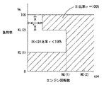
図4および図5を参照して、フィードバック補正量およびその学習値が算出される学習領域について説明する。なお、図4は温間マップにおける学習領域を示し、図5は冷間マップにおける学習領域を示す。 With reference to FIG. 4 and FIG. 5, the learning region in which the feedback correction amount and its learning value are calculated will be described. FIG. 4 shows a learning region in the warm map, and FIG. 5 shows a learning region in the cold map.
図4および図5において互いに隣接する一点鎖線で示す曲線で挟まれた領域が学習領域である。学習領域は、吸入空気量に応じて区分される。吸入空気量に応じた学習領域を設定するのは、エアフローメータ42の出力の誤差が吸入空気量に応じて異なるためである。
In FIG. 4 and FIG. 5, a region sandwiched by curves indicated by alternate long and short dashed lines is a learning region. The learning area is divided according to the intake air amount. The reason why the learning area is set according to the intake air amount is that the error in the output of the
本実施の形態においては、学習領域(1)〜(4)までの4つの学習領域が設けられる。学習領域(1)、学習領域(2)、学習領域(3)、学習領域(4)の順に、吸入空気量が多い。なお、学習領域の数は4つに限らない。 In the present embodiment, four learning areas from learning areas (1) to (4) are provided. The intake air amount increases in the order of the learning area (1), the learning area (2), the learning area (3), and the learning area (4). Note that the number of learning regions is not limited to four.
本実施の形態においては、学習領域に加え、噴射領域(「DI比率r=100%」の領域、「0%<DI比率r<100%」の領域および「DI比率r=0%」の領域)毎にフィードバック補正量およびその学習値が算出される。すなわち、各噴射領域について、学習領域毎にフィードバック補正量およびその学習値が算出される。 In the present embodiment, in addition to the learning area, the injection area ("DI ratio r = 100%" area, "0% <DI ratio r <100%" area, and "DI ratio r = 0%" area) ), The feedback correction amount and its learning value are calculated. That is, for each injection region, the feedback correction amount and its learning value are calculated for each learning region.
図6を参照して、本実施の形態に係る内燃機関の制御装置であるエンジンECU300が実行するプログラムの制御構造について説明する。
With reference to FIG. 6, a control structure of a program executed by
ステップ(以下、ステップをSと略す)100にて、エンジンECU300は、エンジン10の始動要求を検知したか否かを判別する。たとえば、スタートスイッチがオン操作された場合や、イグニッションキーがスタート位置まで操作された場合、エンジン10の始動要求を検知したと判別される。始動要求を検知した場合(S100にてYES)、処理はS102に移される。もしそうでないと(S100にてNO)、処理はS100に戻される。S102にて、エンジンECU300は、過渡的に燃料噴射量を増量してエンジン10をクランキングすることによりエンジン10を始動する。
In step (hereinafter, step is abbreviated as S) 100,
S104にて、エンジンECU300は、水温センサ380から送信された信号に基づいて、エンジン10の冷却水温TWを検知する。S106にて、エンジンECU300は、冷却水温TWがしきい値TW(0)よりも低いか否かを判別する。冷却水温TWがしきい値TW(0)よりも低い場合(S106にてYES)、処理はS108に移される。もしそうでないと(S106にてNO)、この処理は終了する。
In S104,
S108にて、エンジンECU300は、燃料噴射量の過渡増量停止条件が成立したか否かを判別する。ここで、過渡増量停止条件とは、エンジン10が完爆した(エンジン10の回転数が予め定められた回転数よりも高くなった)という条件である。なお、過渡増量停止条件はこれに限らない。
In S108,
過渡増量停止条件が成立した場合(S108にてYES)、処理はS110に移される。もしそうでないと(S108にてNO)、処理はS112に移される。S110にて、エンジンECU300は、燃料噴射量の過渡増量を停止する。S112にて、エンジンECU300は、学習値の算出(更新)を禁止する。
If the transient increase stop condition is satisfied (YES in S108), the process proceeds to S110. If not (NO in S108), the process proceeds to S112. In S110,
S114にて、エンジンECU300は、水温TWに応じて定常的に燃料噴射量を増量する。たとえば、水温TWが低いほど、燃料噴射量が増量される。S116にて、エンジンECU300は、学習値の算出(更新)を許可する。
In S114,
S118にて、エンジンECU300は、燃料噴射量の定常増量停止条件が成立したか否かを判別する。ここで、定常増量停止条件とは、エンジン10の温度、すなわち水温TWが予め定められた温度よりも高くなったという条件である。なお、定常増量停止条件はこれに限らず、その他、たとえば過渡増量を停止してから予め定められた時間が経過したという条件や過渡増量が停止してからの累積回転数が予め定められた回転数を超えたという条件などであってもよい。定常増量停止条件が成立した場合(S118にてYES)、処理はS120に移される。もしそうでないと(S118にてNO)、処理はS118に戻される。
In S118,
S120にて、エンジンECU300は、燃料噴射量の定常増量を停止する。その後、この処理は終了する。
In S120,
以上のような構造およびフローチャートに基づく、本実施の形態に係る内燃機関の制御装置のエンジンECU300の動作について説明する。
An operation of
エンジン10が停止している状態から、始動要求が検知されると(S100にてYES)、図7に示すように、始動性を向上するために、過渡的に燃料噴射量を増量してエンジン10のクランキングが開始されて、エンジン10が始動される(S102)。
If a start request is detected from a state where
この状態では、空燃比が不安定であり、急変し得る。したがって、過渡増量中に学習値を算出すると、学習値が誤算出され、不必要に燃料噴射量が補正されるおそれがある。 In this state, the air-fuel ratio is unstable and can change suddenly. Therefore, if the learning value is calculated during the transient increase, the learning value is erroneously calculated, and the fuel injection amount may be unnecessarily corrected.
「DI比率r=100%」の領域および「0%<DI比率r<100%」の領域における学習値は、エンジン10の暖機後に算出する機会があるため、誤学習による影響は少ないが、「DI比率r=0%」の領域の学習値を算出する機会は冷間時のみであるため、学習値をより精度よく算出する必要がある。
The learning value in the region of “DI ratio r = 100%” and the region of “0% <DI ratio r <100%” has an opportunity to be calculated after the
そのため、エンジンが始動されると、冷却水温TWが検知され(S104)、冷却水温TWがしきい値TW(0)よりも低いか否かが判別される(S106)。冷却水温TWがしきい値TW(0)よりも低い場合(S106にてYES)、すなわちエンジン10の冷間時は、燃料噴射量の過渡増量停止条件が成立したか否かが判別される(S108)。
Therefore, when the engine is started, the coolant temperature TW is detected (S104), and it is determined whether the coolant temperature TW is lower than the threshold value TW (0) (S106). When cooling water temperature TW is lower than threshold value TW (0) (YES in S106), that is, when
燃料噴射量の過渡増量停止条件が成立していない場合(S108にてNO)、すなわち燃料噴射量の過渡増量が継続されている場合、学習値の算出が禁止される(S112)。これにより、空燃比が急変し得る状態で学習値を算出することにより、不必要に燃料噴射量が補正されることを抑制することができる。 When the fuel injection amount transient increase stop condition is not satisfied (NO in S108), that is, when the fuel injection amount transient increase is continued, calculation of the learning value is prohibited (S112). Thereby, it is possible to prevent the fuel injection amount from being unnecessarily corrected by calculating the learning value in a state where the air-fuel ratio can change suddenly.
一方、燃料噴射量の過渡増量停止条件が成立した場合(S108にてYES)、すなわちエンジン10が完爆した場合、燃料噴射量の過渡増量が停止される(S110)。ここでは、図7に示すように、時間T(1)においてエンジン10が完爆した後、燃料噴射量が徐々に減量されて、時間T(2)において燃料噴射量の過渡増量が停止されたと想定する。
On the other hand, when the transient increase stop condition of the fuel injection amount is satisfied (YES in S108), that is, when the
過渡増量の停止後においても、冷間時は燃料が気化し難く、通常の燃料噴射量(温間時の燃料噴射量と同じ噴射量)では、エンジン10の回転数を所望の回転数に維持できないおそれがある。そのため、水温TWに応じて定常的に燃料噴射量が増量される(S114)。なお、このときのエンジン10の運転状態は、アイドル時も含まれる。
Even after the transient increase is stopped, the fuel is difficult to vaporize in the cold state, and the normal engine fuel injection amount (the same fuel injection amount as the warm fuel injection amount) maintains the
定常的に燃料噴射量が増量されている場合、空燃比が安定しているといえる。したがって、この場合に学習値を算出しても、誤算出されるおそれは少ない。また、「DI比率r=0%」の領域の学習値、すなわち吸気通路噴射量インジェクタ120のみから燃料が噴射されている場合の学習値を算出する機会は冷間時に限られている。そのため、冷間時においても、学習値を算出する機会をできるだけ多く確保して、「DI比率r=0%」の領域の学習値を精度よく算出する必要がある。
If the fuel injection amount is constantly increased, it can be said that the air-fuel ratio is stable. Therefore, even if the learning value is calculated in this case, there is little possibility of being erroneously calculated. Further, the opportunity to calculate the learning value in the region of “DI ratio r = 0%”, that is, the learning value when fuel is injected only from the intake passage
そのため、水温TWに応じて定常的に燃料噴射量が増量される状態においては、学習値の算出が許可される(S116)。これにより、空燃比が安定している状態において学習値を算出し、図8に示すように、各噴射領域(特に「DI比率r=0%」の領域)において、学習領域毎に学習値を得ることができる。また、図示しないが、アイドル時に「DI比率r=0%」である場合における学習値を得ることができる。 Therefore, in a state where the fuel injection amount is constantly increased according to the water temperature TW, calculation of the learning value is permitted (S116). As a result, the learning value is calculated in a state where the air-fuel ratio is stable. As shown in FIG. 8, the learning value is calculated for each learning region in each injection region (particularly, the region of “DI ratio r = 0%”). Obtainable. Further, although not shown, it is possible to obtain a learning value when “DI ratio r = 0%” during idling.
なお、図8においては、各噴射領域において、学習領域毎に1つずつ学習値が算出された状態を示す。図8における四角の点は「DI比率r=100%」の領域における学習値を示す。丸の点は「0%<DI比率r<100%」の領域における学習値を示す。三角の点は「DI比率r=0%」の領域における学習値を示す。 FIG. 8 shows a state in which one learning value is calculated for each learning region in each injection region. Square points in FIG. 8 indicate learning values in the region of “DI ratio r = 100%”. Circle points indicate learning values in the region of “0% <DI ratio r <100%”. Triangular points indicate learning values in the region of “DI ratio r = 0%”.
その後、燃料噴射量の定常増量停止条件が成立した場合(S118にてYES)、すなわち、水温TWが予め定められた温度よりも高くなったという条件が成立した場合、燃料噴射量の定常増量が停止される(S120)。 Thereafter, when the steady increase stop condition of the fuel injection amount is satisfied (YES in S118), that is, when the condition that the water temperature TW is higher than a predetermined temperature is satisfied, the steady increase of the fuel injection amount is Stopped (S120).
以上のように、本実施の形態に係る内燃機関の制御装置のエンジンECUによれば、エンジンの冷間時である場合は、エンジン始動時において過渡的に燃料噴射量が増量されている場合、学習値の算出が禁止される。過渡増量の停止後、水温TWに応じて定常的に燃料噴射量が増量されている場合は、学習値の算出が許可される。これにより、空燃比が急変し得る状態における学習値の誤学習を抑制し、精度よく学習値を算出することができる。そのため、不必要に燃料噴射量が補正されることを抑制することができる。その結果、空燃比を適切な状態に制御し、排気エミッション性能を向上することができる。 As described above, according to the engine ECU of the control device for an internal combustion engine according to the present embodiment, when the engine is cold, when the fuel injection amount is transiently increased when the engine is started, Calculation of the learning value is prohibited. If the fuel injection amount is constantly increased according to the water temperature TW after the transient increase is stopped, the learning value is allowed to be calculated. Thereby, it is possible to suppress erroneous learning of the learning value in a state where the air-fuel ratio can change suddenly, and to calculate the learning value with high accuracy. Therefore, it is possible to prevent the fuel injection amount from being corrected unnecessarily. As a result, the air-fuel ratio can be controlled to an appropriate state, and the exhaust emission performance can be improved.
なお、たとえば、吸気ポートの壁面に付着した燃料やキャニスタ(図示せず)からパージされる燃料に基づいて、過渡的に燃料噴射量が補正された場合、空燃比が不安定になる。そのため、水温TWに応じて定常的に燃料噴射量が増量されている期間に、このような補正が行なわれた場合において算出された学習値はRAM330に記憶しないようにして、この学習値に基づく燃料噴射量の補正を禁止するようにしてもよい。
For example, when the fuel injection amount is transiently corrected based on the fuel adhering to the wall surface of the intake port or the fuel purged from the canister (not shown), the air-fuel ratio becomes unstable. Therefore, the learning value calculated when such correction is performed during the period in which the fuel injection amount is constantly increased according to the water temperature TW is not stored in the
<第2の実施の形態>
図9および図10を参照して、本発明の第2の実施の形態について説明する。本実施の形態においては、前述の第1の実施の形態とは異なるマップを用いて、DI比率rを算出する。
<Second Embodiment>
With reference to FIG. 9 and FIG. 10, a second embodiment of the present invention will be described. In the present embodiment, the DI ratio r is calculated using a map different from that of the first embodiment.
その他の構造、処理フローについては、前述の第1の実施の形態と同じである。それらについての機能も同じである。したがって、それらについての詳細な説明はここでは繰返さない。 Other structures and processing flow are the same as those in the first embodiment. The function about them is the same. Therefore, detailed description thereof will not be repeated here.
図9および図10を参照して、エンジン10の運転状態に対応させた情報である、筒内噴射用インジェクタ110と吸気通路噴射用インジェクタ120との噴き分け比率を表わすマップについて説明する。これらのマップは、エンジンECU300のROM320に記憶される。図9は、エンジン10の温間用マップであって、図10は、エンジン10の冷間用マップである。
With reference to FIG. 9 and FIG. 10, a map representing an injection ratio between in-
図9および図10を比較すると、以下の点で図2および図3と異なる。エンジン10の回転数が、温間用マップにおいてはNE(1)以上の領域において、冷間用マップにおいてはNE(3)以上の領域において、「DI比率r=100%」である。また、負荷率が、温間用マップにおいては低回転数領域を除くKL(2)以上の領域において、冷間用マップにおいては低回転数領域を除くKL(4)以上の領域において、「DI比率r=100%」である。これは、予め定められた高エンジン回転数領域では筒内噴射用インジェクタ110のみが使用されること、予め定められた高エンジン負荷領域では筒内噴射用インジェクタ110のみが使用される領域が多いことを示す。しかしながら、低回転数領域の高負荷領域においては、筒内噴射用インジェクタ110から噴射された燃料により形成される混合気のミキシングが良好ではなく、燃焼室内の混合気が不均質で燃焼が不安定になる傾向を有する。このため、このような問題が発生しない高回転数領域へ移行するに伴い筒内噴射用インジェクタの噴射比率を増大させるようにしている。また、このような問題が発生する高負荷領域へ移行するに伴い筒内噴射用インジェクタ110の噴射比率を減少させるようにしている。これらのDI比率rの変化を図9および図10に十字の矢印で示す。このようにすると、燃焼が不安定であることに起因するエンジンの出力トルクの変動を抑制することができる。なお、これらのことは、予め定められた低回転数領域へ移行するに伴い筒内噴射用インジェクタ110の噴射比率を減少させることや、予め定められた低負荷領域へ移行するに伴い筒内噴射用インジェクタ110の噴射比率を増大させることと、略等価であることを確認的に記載する。また、このような領域(図9および図10で十字の矢印が記載された領域)以外の領域であって筒内噴射用インジェクタ110のみで燃料を噴射している領域(高回転側、低負荷側)においては、筒内噴射用インジェクタ110のみでも混合気を均質化しやすい。このようにすると、筒内噴射用インジェクタ110から噴射された燃料は燃焼室内で気化潜熱を伴い(燃焼室から熱を奪い)気化される。これにより、圧縮端での混合気の温度が下がる。これにより対ノッキング性能が向上する。また、燃焼室の温度が下がるので、吸入効率が向上し高出力が見込める。
9 and 10 differ from FIGS. 2 and 3 in the following points. The rotational speed of the
なお、第1および第2の実施の形態において説明したこのエンジン10においては、均質燃焼は筒内噴射用インジェクタ110の燃料噴射タイミングを吸気行程とすることにより、成層燃焼は筒内噴射用インジェクタ110の燃料噴射タイミングを圧縮行程とすることにより実現できる。すなわち、筒内噴射用インジェクタ110の燃料噴射タイミングを圧縮行程とすることで、点火プラグ周りにリッチ混合気が偏在させることにより燃焼室全体としてはリーンな混合気に着火する成層燃焼を実現することができる。また、筒内噴射用インジェクタ110の燃料噴射タイミングを吸気行程としても点火プラグ周りにリッチ混合気を偏在させることができれば、吸気行程噴射であっても成層燃焼を実現できる。
In the
また、ここでいう成層燃焼には、成層燃焼と以下に示す弱成層燃焼の双方を含むものである。弱成層燃焼とは、吸気通路噴射用インジェクタ120を吸気行程で燃料噴射して燃焼室全体にリーンで均質な混合気を生成して、さらに筒内噴射用インジェクタ110を圧縮行程で燃料噴射して点火プラグ周りにリッチな混合気を生成して、燃焼状態の向上を図るものである。このような弱成層燃焼は触媒暖気時に好ましい。これは、以下の理由による。すなわち、触媒暖気時には高温の燃焼ガスを触媒に到達させるために点火時期を大幅に遅角させ、かつ良好な燃焼状態(アイドル状態)を維持する必要がある。また、ある程度の燃料量を供給する必要がある。これを成層燃焼で行なおうとしても燃料量が少ないという問題があり、これを均質燃焼で行なおうとしても良好な燃焼を維持するために遅角量が成層燃焼に比べて小さいという問題がある。このような観点から、上述した弱成層燃焼を触媒暖気時に用いることが好ましいが、成層燃焼および弱成層燃焼のいずれであっても構わない。
Further, the stratified combustion here includes both stratified combustion and weakly stratified combustion described below. In the weak stratified combustion, the
また、第1および第2の実施の形態において説明したエンジンにおいては、筒内噴射用インジェクタ110による燃料噴射のタイミングは、以下のような理由により、圧縮行程で行なうことが好ましい。ただし、上述したエンジン10は、基本的な大部分の領域には(触媒暖気時にのみに行なわれる、吸気通路噴射用インジェクタ120を吸気行程噴射させ、筒内噴射用インジェクタ110を圧縮行程噴射させる弱成層燃焼領域以外を基本的な領域という)、筒内噴射用インジェクタ110による燃料噴射のタイミングは、吸気行程である。しかしながら、以下に示す理由があるので、燃焼安定化を目的として一時的に筒内噴射用インジェクタ110の燃料噴射タイミングを圧縮行程噴射とするようにしてもよい。
In the engine described in the first and second embodiments, the timing of fuel injection by the in-
筒内噴射用インジェクタ110からの燃料噴射時期を圧縮行程中とすることで、筒内温度がより高い時期において、燃料噴射により混合気が冷却される。冷却効果が高まるので、対ノック性を改善することができる。さらに、筒内噴射用インジェクタ110からの燃料噴射時期を圧縮行程中とすると、燃料噴射から点火時期までの時間が短いことから噴霧による気流の強化を実現でき、燃焼速度を上昇させることができる。これらの対ノック性の向上と燃焼速度の上昇とから、燃焼変動を回避して、燃焼安定性を向上させることができる。
By setting the fuel injection timing from the in-
さらに、エンジン10の温度によらず(すなわち、温間時および冷間時のいずれの場合であっても)、オフアイドル時(アイドルスイッチがオフの場合、アクセルペダルが踏まれている場合)には、図2または図9に示す温間マップを用いるようにしてもよい(冷間温間を問わず、低負荷領域において筒内噴射用インジェクタ110を用いる)。
Furthermore, regardless of the temperature of the engine 10 (that is, whether the engine is warm or cold), it is off-idle (when the idle switch is off or the accelerator pedal is depressed). 2 or 9 may be used (the in-
今回開示された実施の形態は、すべての点で例示であって制限的なものではないと考えられるべきである。本発明の範囲は上記した説明ではなくて特許請求の範囲によって示され、特許請求の範囲と均等の意味および範囲内でのすべての変更が含まれることが意図される。 The embodiment disclosed this time should be considered as illustrative in all points and not restrictive. The scope of the present invention is defined by the terms of the claims, rather than the description above, and is intended to include any modifications within the scope and meaning equivalent to the terms of the claims.
10 エンジン、20 インテークマニホールド、30 サージタンク、40 吸気ダクト、42 エアフローメータ、50 エアクリーナ、60 電動モータ、70 スロットルバルブ、80 エキゾーストマニホールド、90 三元触媒コンバータ、100 アクセルペダル、110 筒内噴射用インジェクタ、112 気筒、120 吸気通路噴射用インジェクタ、130 燃料分配管、140 逆止弁、150 高圧燃料ポンプ、152 電磁スピル弁、160 燃料分配管(低圧側)、170 燃料圧レギュレータ、180 低圧燃料ポンプ、190 燃料フィルタ、200 燃料タンク、300 エンジンECU、310 双方向性バス、320 ROM、330 RAM、340 CPU、350 入力ポート、360 出力ポート、370,390,410,430,450 A/D変換器、380 水温センサ、400 燃料圧センサ、420 空燃比センサ、440 アクセル開度センサ、460 回転数センサ。 10 engine, 20 intake manifold, 30 surge tank, 40 air intake duct, 42 air flow meter, 50 air cleaner, 60 electric motor, 70 throttle valve, 80 exhaust manifold, 90 three-way catalytic converter, 100 accelerator pedal, 110 in-cylinder injector , 112 cylinder, 120 Injector injector, 130 Fuel distribution pipe, 140 Check valve, 150 High pressure fuel pump, 152 Electromagnetic spill valve, 160 Fuel distribution pipe (low pressure side), 170 Fuel pressure regulator, 180 Low pressure fuel pump, 190 fuel filter, 200 fuel tank, 300 engine ECU, 310 bidirectional bus, 320 ROM, 330 RAM, 340 CPU, 350 input port, 360 output port, 370, 39 , 410,430,450 A / D converter, 380 a water temperature sensor, 400 a fuel pressure sensor, 420 an air-fuel ratio sensor, 440 an accelerator opening sensor, 460 rpm sensor.
Claims (4)
少なくとも前記内燃機関の温度が予め定められた値以下の、クランキング時およびアイドル時において、前記第1の燃料噴射手段および前記第2の燃料噴射手段のいずれか一方のみから燃料が噴射されるように、前記燃料噴射手段を制御するための第1の制御手段と、
前記第1の燃料噴射手段および前記第2の燃料噴射手段から燃料が噴射されるように、前記燃料噴射手段を制御するための第2の制御手段と、
空燃比に基づいて燃料噴射量のフィードバック補正値を算出するための第1の算出手段と、
予め定められた条件が成立した場合、前記フィードバック補正量の学習値を算出するための第2の算出手段と、
少なくとも前記内燃機関のクランキング開始時から完爆するまでの期間において、前記学習値の算出を禁止するための禁止手段と、
前記内燃機関の完爆後のアイドル時の、前記内燃機関の温度に基づいて燃料噴射量が補正される期間において、前記学習値の算出を許可するための許可手段とを含む、内燃機関の制御装置。 A control device for an internal combustion engine comprising a first fuel injection means for injecting fuel into a cylinder and a second fuel injection means for injecting fuel into an intake passage,
At least at the time of cranking and idling when the temperature of the internal combustion engine is equal to or lower than a predetermined value , fuel is injected from only one of the first fuel injection means and the second fuel injection means. First control means for controlling the fuel injection means;
Second control means for controlling the fuel injection means such that fuel is injected from the first fuel injection means and the second fuel injection means;
First calculation means for calculating a feedback correction value of the fuel injection amount based on the air-fuel ratio;
A second calculating means for calculating a learning value of the feedback correction amount when a predetermined condition is satisfied;
Prohibiting means for prohibiting calculation of the learning value at least during a period from the start of cranking of the internal combustion engine to a complete explosion;
Control means for permitting calculation of the learned value during a period in which the fuel injection amount is corrected based on the temperature of the internal combustion engine when the internal combustion engine is idle after a complete explosion apparatus.
前記第2の燃料噴射手段は、吸気通路用インジェクタである、請求項1〜3のいずれかに記載の内燃機関の制御装置。 The first fuel injection means is an in-cylinder injector,
The control device for an internal combustion engine according to any one of claims 1 to 3, wherein the second fuel injection means is an intake passage injector.
Priority Applications (6)
| Application Number | Priority Date | Filing Date | Title |
|---|---|---|---|
| JP2005078292A JP4470771B2 (en) | 2005-03-18 | 2005-03-18 | Control device for internal combustion engine |
| PCT/JP2006/301718 WO2006100834A1 (en) | 2005-03-18 | 2006-01-26 | Control device for internal combustion engine |
| EP06712861A EP1859146B1 (en) | 2005-03-18 | 2006-01-26 | Control device for internal combustion engine |
| CN200680008782A CN100580239C (en) | 2005-03-18 | 2006-01-26 | Control device for internal combustion engine |
| US11/339,776 US7318412B2 (en) | 2005-03-18 | 2006-01-26 | Control device for internal combustion engine |
| DE602006011717T DE602006011717D1 (en) | 2005-03-18 | 2006-01-26 | CONTROL DEVICE FOR INTERNAL COMBUSTION ENGINE |
Applications Claiming Priority (1)
| Application Number | Priority Date | Filing Date | Title |
|---|---|---|---|
| JP2005078292A JP4470771B2 (en) | 2005-03-18 | 2005-03-18 | Control device for internal combustion engine |
Publications (3)
| Publication Number | Publication Date |
|---|---|
| JP2006258010A JP2006258010A (en) | 2006-09-28 |
| JP2006258010A5 JP2006258010A5 (en) | 2008-04-10 |
| JP4470771B2 true JP4470771B2 (en) | 2010-06-02 |
Family
ID=36643399
Family Applications (1)
| Application Number | Title | Priority Date | Filing Date |
|---|---|---|---|
| JP2005078292A Expired - Fee Related JP4470771B2 (en) | 2005-03-18 | 2005-03-18 | Control device for internal combustion engine |
Country Status (6)
| Country | Link |
|---|---|
| US (1) | US7318412B2 (en) |
| EP (1) | EP1859146B1 (en) |
| JP (1) | JP4470771B2 (en) |
| CN (1) | CN100580239C (en) |
| DE (1) | DE602006011717D1 (en) |
| WO (1) | WO2006100834A1 (en) |
Families Citing this family (13)
| Publication number | Priority date | Publication date | Assignee | Title |
|---|---|---|---|---|
| DE102004058714B4 (en) * | 2004-12-06 | 2006-08-31 | Siemens Ag | Method and device for checking temperature values of a temperature sensor of an internal combustion engine |
| JP2007023908A (en) * | 2005-07-19 | 2007-02-01 | Nikki Co Ltd | Method and device for controlling fuel supply of internal combustion engine |
| US20090090332A1 (en) * | 2007-10-03 | 2009-04-09 | Brehob Diana D | Method and System to Mitigate Deposit Formation on a Direct Injector for a Gasoline-Fuelled Internal Combustion Engine |
| EP2222945B1 (en) * | 2007-11-13 | 2016-11-02 | Toyota Jidosha Kabushiki Kaisha | Control device for internal combustion engine |
| US9291139B2 (en) * | 2008-08-27 | 2016-03-22 | Woodward, Inc. | Dual action fuel injection nozzle |
| KR101628488B1 (en) * | 2014-09-25 | 2016-06-08 | 현대자동차주식회사 | Method for controlling of ETC changed carbon deposit |
| AT516532B1 (en) * | 2014-11-24 | 2019-10-15 | Innio Jenbacher Gmbh & Co Og | Method for starting an internal combustion engine operated with a fuel-air mixture |
| JP6681251B2 (en) * | 2016-04-05 | 2020-04-15 | ヤンマー株式会社 | Engine control method |
| US10914264B2 (en) * | 2016-06-23 | 2021-02-09 | Toyota Jidosha Kabushiki Kaisha | Air-fuel ratio control apparatus and method for internal combustion engine |
| JP6341235B2 (en) * | 2016-07-20 | 2018-06-13 | トヨタ自動車株式会社 | Engine air-fuel ratio control device |
| JP6638668B2 (en) * | 2017-02-14 | 2020-01-29 | トヨタ自動車株式会社 | Fuel injection control device |
| US10801433B2 (en) * | 2018-04-24 | 2020-10-13 | GM Global Technology Operations LLC | Systems and methods for determining irregular fuel requests during engine idle conditions |
| JP7183962B2 (en) * | 2019-06-05 | 2022-12-06 | トヨタ自動車株式会社 | Control device for internal combustion engine |
Family Cites Families (11)
| Publication number | Priority date | Publication date | Assignee | Title |
|---|---|---|---|---|
| JPS59194053A (en) * | 1983-04-18 | 1984-11-02 | Toyota Motor Corp | Method and device of air-fuel ratio control for internal- combustion engine |
| JPH03185242A (en) | 1989-12-14 | 1991-08-13 | Toyota Motor Corp | Fuel injection controller of internal combustion engine |
| JPH04224244A (en) * | 1990-12-21 | 1992-08-13 | Honda Motor Co Ltd | Air fuel ratio control device of engine |
| JPH04241756A (en) | 1991-01-11 | 1992-08-28 | Japan Electron Control Syst Co Ltd | Air-fuel ratio study control device for internal combustion engine |
| US5482023A (en) * | 1994-12-27 | 1996-01-09 | Hitachi America, Ltd., Research And Development Division | Cold start fuel control system |
| US5598826A (en) | 1994-12-27 | 1997-02-04 | Hitachi America, Ltd. | Cold start fuel control system for an internal combustion engine |
| JP2000227041A (en) | 1999-02-04 | 2000-08-15 | Mazda Motor Corp | Control device for cylinder injection type engine |
| EP1138901A3 (en) * | 2000-03-29 | 2004-04-07 | Hitachi, Ltd. | Fuel supply system for internal combustion engine |
| JP2002206445A (en) | 2001-01-10 | 2002-07-26 | Hitachi Ltd | Fuel supply device for internal combustion engine |
| US6591817B2 (en) * | 2001-03-21 | 2003-07-15 | Motorola, Inc. | Dual fuel method and system |
| US7159568B1 (en) * | 2005-11-30 | 2007-01-09 | Ford Global Technologies, Llc | System and method for engine starting |
-
2005
- 2005-03-18 JP JP2005078292A patent/JP4470771B2/en not_active Expired - Fee Related
-
2006
- 2006-01-26 DE DE602006011717T patent/DE602006011717D1/en active Active
- 2006-01-26 EP EP06712861A patent/EP1859146B1/en not_active Expired - Fee Related
- 2006-01-26 CN CN200680008782A patent/CN100580239C/en not_active Expired - Fee Related
- 2006-01-26 US US11/339,776 patent/US7318412B2/en active Active
- 2006-01-26 WO PCT/JP2006/301718 patent/WO2006100834A1/en not_active Application Discontinuation
Also Published As
| Publication number | Publication date |
|---|---|
| US20060207557A1 (en) | 2006-09-21 |
| EP1859146A1 (en) | 2007-11-28 |
| WO2006100834A1 (en) | 2006-09-28 |
| JP2006258010A (en) | 2006-09-28 |
| EP1859146B1 (en) | 2010-01-13 |
| DE602006011717D1 (en) | 2010-03-04 |
| CN100580239C (en) | 2010-01-13 |
| US7318412B2 (en) | 2008-01-15 |
| CN101142393A (en) | 2008-03-12 |
Similar Documents
| Publication | Publication Date | Title |
|---|---|---|
| JP4470771B2 (en) | Control device for internal combustion engine | |
| JP4470772B2 (en) | Internal combustion engine state determination device | |
| JP4470773B2 (en) | Control device for internal combustion engine | |
| JP4487735B2 (en) | Control device for internal combustion engine | |
| JP4453625B2 (en) | Control device for internal combustion engine | |
| JP4462079B2 (en) | Control device for internal combustion engine | |
| US7258102B2 (en) | Control device for internal combustion engine | |
| JP4595952B2 (en) | Control device for internal combustion engine, control method, program for realizing the method, and recording medium recording the program | |
| JP4643323B2 (en) | Control device for internal combustion engine | |
| JP2006258017A (en) | Control device of internal combustion engine | |
| KR20080070751A (en) | Control apparatus for internal combustion engine | |
| JP4453524B2 (en) | Control device for internal combustion engine | |
| JP4513613B2 (en) | Abnormality determination device for internal combustion engine | |
| JP4548256B2 (en) | Control device for internal combustion engine | |
| JP4640012B2 (en) | Internal combustion engine state determination device | |
| JP4701897B2 (en) | Control device for internal combustion engine | |
| JP2006258025A (en) | Control device of internal combustion engine | |
| JP2006138249A (en) | Control device for internal combustion engine | |
| JP4407551B2 (en) | Control device for internal combustion engine | |
| JP4706368B2 (en) | Control device for internal combustion engine | |
| JP4432663B2 (en) | Control device for internal combustion engine | |
| JP2007032314A (en) | State determination device of internal combustion engine |
Legal Events
| Date | Code | Title | Description |
|---|---|---|---|
| A521 | Request for written amendment filed |
Free format text: JAPANESE INTERMEDIATE CODE: A523 Effective date: 20080225 |
|
| A621 | Written request for application examination |
Free format text: JAPANESE INTERMEDIATE CODE: A621 Effective date: 20080225 |
|
| A131 | Notification of reasons for refusal |
Free format text: JAPANESE INTERMEDIATE CODE: A131 Effective date: 20091104 |
|
| A521 | Request for written amendment filed |
Free format text: JAPANESE INTERMEDIATE CODE: A523 Effective date: 20091224 |
|
| TRDD | Decision of grant or rejection written | ||
| A01 | Written decision to grant a patent or to grant a registration (utility model) |
Free format text: JAPANESE INTERMEDIATE CODE: A01 Effective date: 20100209 |
|
| A01 | Written decision to grant a patent or to grant a registration (utility model) |
Free format text: JAPANESE INTERMEDIATE CODE: A01 |
|
| A61 | First payment of annual fees (during grant procedure) |
Free format text: JAPANESE INTERMEDIATE CODE: A61 Effective date: 20100222 |
|
| FPAY | Renewal fee payment (event date is renewal date of database) |
Free format text: PAYMENT UNTIL: 20130312 Year of fee payment: 3 |
|
| R151 | Written notification of patent or utility model registration |
Ref document number: 4470771 Country of ref document: JP Free format text: JAPANESE INTERMEDIATE CODE: R151 |
|
| FPAY | Renewal fee payment (event date is renewal date of database) |
Free format text: PAYMENT UNTIL: 20130312 Year of fee payment: 3 |
|
| FPAY | Renewal fee payment (event date is renewal date of database) |
Free format text: PAYMENT UNTIL: 20130312 Year of fee payment: 3 |
|
| FPAY | Renewal fee payment (event date is renewal date of database) |
Free format text: PAYMENT UNTIL: 20140312 Year of fee payment: 4 |
|
| LAPS | Cancellation because of no payment of annual fees |