JP4468120B2 - Image supply device, method for controlling the device, program thereof, and storage medium - Google Patents
Image supply device, method for controlling the device, program thereof, and storage medium Download PDFInfo
- Publication number
- JP4468120B2 JP4468120B2 JP2004267513A JP2004267513A JP4468120B2 JP 4468120 B2 JP4468120 B2 JP 4468120B2 JP 2004267513 A JP2004267513 A JP 2004267513A JP 2004267513 A JP2004267513 A JP 2004267513A JP 4468120 B2 JP4468120 B2 JP 4468120B2
- Authority
- JP
- Japan
- Prior art keywords
- image
- image data
- printer
- printed
- file
- Prior art date
- Legal status (The legal status is an assumption and is not a legal conclusion. Google has not performed a legal analysis and makes no representation as to the accuracy of the status listed.)
- Expired - Fee Related
Links
Images


Classifications
-
- H—ELECTRICITY
- H04—ELECTRIC COMMUNICATION TECHNIQUE
- H04N—PICTORIAL COMMUNICATION, e.g. TELEVISION
- H04N1/00—Scanning, transmission or reproduction of documents or the like, e.g. facsimile transmission; Details thereof
- H04N1/32—Circuits or arrangements for control or supervision between transmitter and receiver or between image input and image output device, e.g. between a still-image camera and its memory or between a still-image camera and a printer device
- H04N1/333—Mode signalling or mode changing; Handshaking therefor
- H04N1/33376—Mode signalling or mode changing; Handshaking therefor according to characteristics or state of one of the communicating parties, e.g. available memory capacity
-
- H—ELECTRICITY
- H04—ELECTRIC COMMUNICATION TECHNIQUE
- H04N—PICTORIAL COMMUNICATION, e.g. TELEVISION
- H04N1/00—Scanning, transmission or reproduction of documents or the like, e.g. facsimile transmission; Details thereof
- H04N1/00127—Connection or combination of a still picture apparatus with another apparatus, e.g. for storage, processing or transmission of still picture signals or of information associated with a still picture
- H04N1/00278—Connection or combination of a still picture apparatus with another apparatus, e.g. for storage, processing or transmission of still picture signals or of information associated with a still picture with a printing apparatus, e.g. a laser beam printer
-
- H—ELECTRICITY
- H04—ELECTRIC COMMUNICATION TECHNIQUE
- H04N—PICTORIAL COMMUNICATION, e.g. TELEVISION
- H04N2201/00—Indexing scheme relating to scanning, transmission or reproduction of documents or the like, and to details thereof
- H04N2201/0008—Connection or combination of a still picture apparatus with another apparatus
- H04N2201/0015—Control of image communication with the connected apparatus, e.g. signalling capability
-
- H—ELECTRICITY
- H04—ELECTRIC COMMUNICATION TECHNIQUE
- H04N—PICTORIAL COMMUNICATION, e.g. TELEVISION
- H04N2201/00—Indexing scheme relating to scanning, transmission or reproduction of documents or the like, and to details thereof
- H04N2201/0008—Connection or combination of a still picture apparatus with another apparatus
- H04N2201/0034—Details of the connection, e.g. connector, interface
- H04N2201/0037—Topological details of the connection
- H04N2201/0041—Point to point
-
- H—ELECTRICITY
- H04—ELECTRIC COMMUNICATION TECHNIQUE
- H04N—PICTORIAL COMMUNICATION, e.g. TELEVISION
- H04N2201/00—Indexing scheme relating to scanning, transmission or reproduction of documents or the like, and to details thereof
- H04N2201/0008—Connection or combination of a still picture apparatus with another apparatus
- H04N2201/0065—Converting image data to a format usable by the connected apparatus or vice versa
- H04N2201/0068—Converting from still picture data
-
- H—ELECTRICITY
- H04—ELECTRIC COMMUNICATION TECHNIQUE
- H04N—PICTORIAL COMMUNICATION, e.g. TELEVISION
- H04N2201/00—Indexing scheme relating to scanning, transmission or reproduction of documents or the like, and to details thereof
- H04N2201/0077—Types of the still picture apparatus
- H04N2201/0084—Digital still camera
-
- H—ELECTRICITY
- H04—ELECTRIC COMMUNICATION TECHNIQUE
- H04N—PICTORIAL COMMUNICATION, e.g. TELEVISION
- H04N2201/00—Indexing scheme relating to scanning, transmission or reproduction of documents or the like, and to details thereof
- H04N2201/32—Circuits or arrangements for control or supervision between transmitter and receiver or between image input and image output device, e.g. between a still-image camera and its memory or between a still-image camera and a printer device
- H04N2201/333—Mode signalling or mode changing; Handshaking therefor
- H04N2201/33307—Mode signalling or mode changing; Handshaking therefor of a particular mode
- H04N2201/33314—Mode signalling or mode changing; Handshaking therefor of a particular mode of reading or reproducing mode
- H04N2201/33321—Image or page size, e.g. A3, A4
Landscapes
- Engineering & Computer Science (AREA)
- Multimedia (AREA)
- Signal Processing (AREA)
- Television Signal Processing For Recording (AREA)
- Accessory Devices And Overall Control Thereof (AREA)
- Editing Of Facsimile Originals (AREA)
- Studio Devices (AREA)
Description
本発明は、印刷装置に画像データを供給して印刷させる画像供給デバイス及び該デバイスの制御方法に関するものである。 The present invention relates to an image supply device that supplies image data to a printing apparatus for printing, and a control method for the device.
プリンタとデジタルスチルカメラ(以下DSC)とをUSB等のインタフェースを介して直接接続し、DSCの記憶媒体(メモリカード)に記憶されている写真画像をプリンタに送信して印刷する、所謂、デジタルカメラダイレクトプリントシステムが一般的となってきている。 A so-called digital camera in which a printer and a digital still camera (hereinafter DSC) are directly connected via an interface such as a USB, and a photographic image stored in a DSC storage medium (memory card) is transmitted to the printer for printing. Direct print systems have become commonplace.
このようなプリントシステムでは、一般的にはDSCから、印刷対象となる画像のJPEGファイルをプリンタに送信し、プリンタ側で、そのJPEGファイルの解凍、色変換、リサイズ等を行ってプリント可能なデータ形式へ変換して印刷を行っている。 In such a printing system, in general, a JPEG file of an image to be printed is transmitted from a DSC to a printer, and the printer can decompress the JPEG file, perform color conversion, resize, etc., and printable data. It is converted to a format and printed.
一方、DSCで、撮影画像をプリント専用に処理した後プリンタに送信して印刷するシステムが提案されている(特許文献1〜3)。
On the other hand, a system has been proposed in which a captured image is processed exclusively for printing by DSC and then transmitted to a printer for printing (
特許文献1では、一般性の低い固有のプリントプロトコルを用いて、DSCからの画像と、プリンタ側の用紙サイズ等の印刷態様に応じた画像の印刷を可能とするデジタルカメラダイレクトプリントシステムが提案されている。
特許文献2では、プリンタでの処理負荷の低減を目的とし、DSCでJPEGファイルの解凍、色変換、リサイズ等を行ってプリント可能なデータ形式へ変換処理を行い、プリント可能なデータとしてプリンタに送信し、プリンタでの画像処理負荷の低減を図っている。 In Patent Document 2, for the purpose of reducing the processing load on the printer, the DSC decompresses the JPEG file, performs color conversion, resizing, etc., converts it into a printable data format, and sends it to the printer as printable data. However, the image processing load on the printer is reduced.
更に特許文献3では、プリンタ毎の色再現特性のばらつきをDSC側で補正し、JPEGなどの一般的な画像ファイルに変換してプリンタに送信している。これによりプリンタ毎の印刷特性に依存しない安定した画像を得ることが記載されている。
上述のデジタルカメラダイレクトプリントシステムにおける通信手順を規定したPictBridgeと呼ばれる規格により、デジタルカメラダイレクトプリントシステムが益々普及してきており、更に、DSCにおける画像の高画質化の進歩も著しいものがある。DSCで撮像されて記憶される画像データの解像度は、数年前までは最大100〜200万画素/画像だったのもが、近年では、一画像当り800万画素以上の高解像度の画像を撮影して記憶できるDSCが販売されている。 Due to the standard called PictBridge that defines the communication procedure in the above-described digital camera direct print system, the digital camera direct print system is becoming more and more popular, and further, the improvement in image quality in the DSC is remarkable. The resolution of image data captured and stored by DSC was a maximum of 1 to 2 million pixels / image until several years ago, but in recent years, high-resolution images of 8 million pixels or more per image have been captured. Memorable DSCs are on sale.
このようなDSCにおける解像度の増大に伴い、上述のデジタルカメラダイレクトプリントシステムにおいて、本願発明者は以下のような新たな課題を見つけるに至った。
(1)プリンタ側での処理すべき画素数が大きくなり、プリンタの負荷が増大する。
(2)画素数に合わせて画像ファイルサイズが大きくなり、DSC−プリンタ間での画像ファイルの転送負荷が増大する。
With the increase in resolution in the DSC, the present inventor has found the following new problem in the above-described digital camera direct print system.
(1) The number of pixels to be processed on the printer side increases, and the load on the printer increases.
(2) The image file size increases in accordance with the number of pixels, and the transfer load of the image file between the DSC and the printer increases.
これらが要因となり、印刷時にプリント速度が低下するという問題が発生している。 Due to these factors, there is a problem that the printing speed is reduced during printing.
先述の公知例のような処理の負荷分散を目的として、印刷用の画像データの画像処理の一部をDSCで行う場合の問題点があることが新たに解った。また、いずれの公知例においても、プリンタが有する印刷態様や印刷特性をプリンタから取得する旨の記載があるが、そのプリンタの印刷特性に関する情報をプリンタとDSC間での通信する方法について具体的な記載が無い。例えば、プリンタの印刷能力をDSCに伝える手法では、プリンタによる印刷時のサイズ/レイアウト等の印刷形態を、そのプリンタのCapabilityで許容する範囲内であればDSC側でユーザが任意に設定及び選択できる。このようなプリントシステムでは、DSCでのプリンタの印刷条件をDSCから設定する場合、プリンタからの情報のみでは適切に設定されるとは限らない。特に特許文献1では、プリンタが、現在印刷可能な印刷態様をDSCに通知し、DSCではそれに従って印刷態様を変更している。例えば、A4サイズの用紙がプリンタ本体にセットされていて、紙サイズ検知機能を有しているプリンタでは、DSCに対して自動的に用紙サイズがA4として通知するように記載されている。また紙サイズ検知機能がない場合は、プリンタ本体の設定パネルで用紙サイズを選択し、その結果をDSCに通知している。いずれの場合も、プリンタが認知している現在の印刷態様をDSCに通知するものであり、DSCにおいてユーザが希望し設定した結果が反映されない。
It has been newly found that there is a problem when a part of image processing of image data for printing is performed by DSC for the purpose of distributing the processing load as in the above-described known example. In each of the known examples, there is a description that the printing mode and printing characteristics of the printer are acquired from the printer. A specific method for communicating information about the printing characteristics of the printer between the printer and the DSC is described in detail. There is no description. For example, in the method of transmitting the printing capability of a printer to the DSC, the user can arbitrarily set and select the printing mode such as the size / layout at the time of printing by the printer within the range permitted by the Capability of the printer. . In such a printing system, when the printing condition of the printer in the DSC is set from the DSC, the information from the printer alone is not always set appropriately. In particular, in
また特許文献2及び3には、プリンタにおける印刷特性をプリンタから取得する旨の記載があるが、その取得した印刷特性だけに基づいてプリンタに送信する画像データの変換を実行しているため、ユーザの希望に則した画像処理や印刷処理を行う点については記載されていない。 Patent Documents 2 and 3 describe that the print characteristics of the printer are acquired from the printer. However, since conversion of image data to be transmitted to the printer is executed based only on the acquired print characteristics, the user can However, it does not describe the point of performing image processing or printing processing in accordance with the desires.
本発明は上記問題点に鑑みてなされたもので、印刷装置に送信する画像データを処理して印刷装置に送信する画像供給デバイス及びその制御方法を提供することにある。 The present invention has been made in view of the above problems, it is to provide an image supply device and a control how and transmits the processed image data to be transmitted to the printing apparatus to the printing apparatus.
本発明の一態様に係る画像供給デバイスは以下のような構成を備える。即ち、
印刷装置と所定の通信プロトコルで通信し、当該印刷装置に画像データを供給する画像供給デバイスであって、
印刷装置との通信開始に応じて、前記印刷装置との通信プロトコルのバージョンに関する情報を取得する取得手段と、
印刷対象の画像ファイルを指定する指定手段と、
前記印刷対象の画像ファイルの画像データを回転する回転手段と、
前記回転手段により回転させた画像データを前記印刷装置へ送信する送信手段と、
前記取得手段により取得した通信プロトコルのバージョンに基づいて、前記指定手段で指定された前記印刷対象の画像ファイルの画像データを前記回転手段により回転させるか否かを決定する決定手段と、を有することを特徴とする。
An image supply device according to an aspect of the present invention has the following configuration. That is,
An image supply device that communicates with a printing apparatus using a predetermined communication protocol and supplies image data to the printing apparatus,
An acquisition means for acquiring information relating to a version of a communication protocol with the printing apparatus in response to the start of communication with the printing apparatus;
And designating means for designating the image file to be printed,
Rotating means for rotating the image data of the image file of the print subject,
Transmitting means for transmitting the image data rotated by the rotating means to the printing apparatus;
Determining means for determining whether or not to rotate the image data of the image file to be printed designated by the designation means based on the version of the communication protocol obtained by the obtaining means; It is characterized by.
本発明の一態様に係る画像供給デバイスの制御方法は以下のような工程を備える。即ち、
印刷装置と所定の通信プロトコルで通信し、当該印刷装置に画像データを供給する画像供給デバイスの制御方法であって、
印刷装置との通信開始に応じて、前記印刷装置との通信プロトコルのバージョンに関する情報を取得する取得工程と、
印刷対象の画像ファイルを指定する指定工程と、
前記印刷対象の画像ファイルの画像データを回転する回転工程と、
前記回転工程で回転させた画像データを前記印刷装置へ送信する送信工程と、
前記取得工程で取得した通信プロトコルのバージョンに基づいて、前記指定工程で指定された前記印刷対象の画像ファイルの画像データを前記回転工程で回転させるか否かを決定する決定工程と、を有することを特徴とする。
An image supply device control method according to an aspect of the present invention includes the following steps. That is,
A method for controlling an image supply device that communicates with a printing apparatus using a predetermined communication protocol and supplies image data to the printing apparatus,
An acquisition step in response to communication start of the printing apparatus, to obtain information about the version of the communication protocol with the printing device,
A specification process for specifying an image file to be printed;
A rotation step of rotating the image data of the image file of the print subject,
A transmission step of transmitting the image data rotated in the rotation step to the printing apparatus;
And a determining step for determining whether or not to rotate the image data of the image file to be printed specified in the specifying step based on the version of the communication protocol acquired in the acquiring step. It is characterized by.
本発明によれば、印刷装置における印刷特性で、かつ印刷範囲に収まるように画像データを変換して印刷装置に画像データを送信するため、印刷装置では特別で高価な画像処理機能を設ける必要が無く、画像処理が簡略化できる。これにより高速に印刷することが可能となる。 According to the present invention, since the image data is converted so as to be within the printing range and within the printing range in the printing apparatus and the image data is transmitted to the printing apparatus, the printing apparatus needs to be provided with a special and expensive image processing function. And image processing can be simplified. This makes it possible to print at high speed.
以下、添付図面を参照して本発明の好適な実施の形態を詳しく説明する。尚、本実施の形態では、デジタルカメラ(DSC)とプリンタとの間でダイレクトプリントを実現する場合で説明するが、本発明はこれに限定されるものではない。 Hereinafter, preferred embodiments of the present invention will be described in detail with reference to the accompanying drawings. In this embodiment, a case where direct printing is realized between a digital camera (DSC) and a printer will be described. However, the present invention is not limited to this.
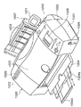
図1は、本発明の実施の形態に係るフォトダイレクトプリンタ装置(以下、PDプリンタ)1000の概観斜視図である。このPDプリンタ1000は、ホストコンピュータ(PC)からデータを受信して印刷する通常のPCプリンタとしての機能と、メモリカードなどの記憶媒体に記憶されている画像データを直接読取って印刷したり、或いはデジタルカメラやPDAなどからの画像データを受信して印刷する機能を備えている。
FIG. 1 is a schematic perspective view of a photo direct printer apparatus (hereinafter referred to as PD printer) 1000 according to an embodiment of the present invention. The
図1において、本実施の形態に係るPDプリンタ1000の外殻をなす本体は、下ケース1001、上ケース1002、アクセスカバー1003及び排出トレイ1004の外装部材を有している。また、下ケース1001は、PDプリンタ1000の略下半部を、上ケース1002は本体の略上半部をそれぞれ形成しており、両ケースの組合せによって内部に後述の各機構を収納する収納空間を有する中空体構造をなし、その上面部及び前面部にはそれぞれ開口部がされている。さらに、排出トレイ1004は、その一端部が下ケース1001に回転自在に保持され、その回転によって下ケース1001の前面部に形成される開口部を開閉させ得るようになっている。このため、記録動作を実行させる際には、排出トレイ1004を前面側へと回転させて開口部を開成させることにより、ここから記録されたシート(普通紙、専用紙、樹脂シート等を含む。以下単にシートとする)が排出可能となると共に、排出されたシートを順次積載し得るようになっている。また排紙トレイ1004には、2枚の補助トレイ1004a,1004bが収納されており、必要に応じて各トレイを手前に引き出すことにより、シートの支持面積を3段階に拡大、縮小させ得るようになっている。
In FIG. 1, the main body that forms the outer shell of the
アクセスカバー1003は、その一端部が上ケース1002に回転自在に保持され、上面に形成される開口部を開閉し得るようになっており、このアクセスカバー1003を開くことによって本体内部に収納されている記録ヘッドカートリッジ(不図示)或いはインクタンク(不図示)等の交換が可能となる。尚、ここでは特に図示しないが、アクセスカバー1003を開閉させると、その裏面に形成された突起がカバー開閉レバーを回転させるようになっており、そのレバーの回転位置をマイクロスイッチなどで検出することにより、アクセスカバー1003の開閉状態を検出し得るようになっている。
One end of the
また、上ケース1002の上面には、電源キー1005が設けられている。また、上ケース1002の右側には、液晶表示部1006や各種キースイッチ等を備える操作パネル1010が設けられている。この操作パネル1010の構造は、図2を参照して詳しく後述する。1007は自動給送部で、シートを装置本体内へと自動的に給送する。1008は紙間選択レバーで、プリントヘッドとシートとの間隔を調整するためのレバーである。1009はカードスロットで、ここにメモリカードを装着可能なアダプタが挿入され、このアダプタを介してメモリカードに記憶されている画像データを直接取り込んで印刷することができる。このメモリカード(PC)としては、例えばコンパクトフラッシュ(登録商標)メモリ、スマートメディア、メモリスティック等がある。1011はビューワ(液晶表示部)で、このPDプリンタ1000の本体に着脱可能であり、PCカードに記憶されている画像の中からプリントしたい画像を検索する場合などに、1コマ毎の画像やインデックス画像などを表示するのに使用される。1012は後述するデジタルカメラを接続するためのUSB端子である。また、このPD装置1000の後面には、パーソナルコンピュータ(PC)を接続するためのUSBコネクタが設けられている。
A
図2は本実施の形態に係るPDプリンタ1000の操作パネル1010の概観図である。
FIG. 2 is an overview of the
図において、液晶表示部1006には、その左右に印刷されている項目に関するデータを各種設定するためのメニュー項目が表示される。ここに表示される項目としては、例えば、複数ある写真画像ファイルの内、印刷したい写真画像の先頭番号、指定コマ番号(開始コマ指定/印刷コマ指定)、印刷を終了したい最後の写真番号(終了)、印刷部数(部数)、印刷に使用するシートの種類(用紙種類)、1枚のシートに印刷する写真の枚数設定(レイアウト)、印刷の品位の指定(品位)、撮影した日付を印刷するかどうかの指定(日付印刷)、写真を補正して印刷するかどうかの指定(画像補正)、印刷に必要なシートの枚数表示(用紙枚数)等がある。これら各項目は、カーソルキー2001を用いて選択、或いは指定される。2002はモードキーで、このキーを押下する毎に、印刷の種類(インデックス印刷、全コマ印刷、1コマ印刷、指定コマ印刷等)を切り替えることができ、これに応じてLED2003の対応するLEDが点灯される。2004はメンテナンスキーで、プリントヘッドのクリーニング等、プリンタのメンテナンスを行わせるためのキーである。2005は印刷開始キーで、印刷の開始を指示する時、或いはメンテナンスの設定を確立する際に押下される。2006は印刷中止キーで、印刷を中止させる時や、メンテナンスの中止を指示する際に押下される。
In the figure, the liquid
次に図3を参照して、本実施の形態に係るPDプリンタ1000の制御に係る主要部の構成を説明する。尚、この図3において、前述の図面と共通する部分は同じ記号を付与して、それらの説明を省略する。
Next, with reference to FIG. 3, the configuration of the main part relating to the control of the
図3は、本実施の形態に係るPDプリンタの制御に係る主要部の構成を示すブロック図である。 FIG. 3 is a block diagram showing a configuration of a main part related to the control of the PD printer according to the present embodiment.
図3において、3000は制御部(制御基板)を示している。3001はASIC(専用カスタムLSI)を示している。3002はDSP(デジタル信号処理プロセッサ)で、内部にCPUを有し、後述する各種制御処理及び、輝度信号(RGB)から濃度信号(CMYK)への変換、スケーリング、ガンマ変換、誤差拡散等の画像処理等を担当している。3003はメモリで、DSP3002のCPUの制御プログラムを記憶するプログラムメモリ3003a、及び実行時のプログラムを記憶するRAMエリア、画像データなどを記憶するワークメモリとして機能するメモリエリアを有している。3004はプリンタエンジンで、ここでは、複数色のカラーインクを用いてカラー画像を印刷するインクジェットプリンタのプリンタエンジンが搭載されている。3005はデジタルカメラ(DSC)3012を接続するためのポートとしてのUSBコネクタである。3006はビューワ1011を接続するためのコネクタである。3008はUSBハブ(USBHUB)で、このPDプリンタ1000がPC3010からの画像データに基づいて印刷を行う際には、PC3010からのデータをそのままスルーし、USB3021を介してプリンタエンジン3004に出力する。これにより、接続されているPC3010は、プリンタエンジン3004と直接、データや信号のやり取りを行って印刷を実行することができる(一般的なPCプリンタとして機能する)。3009は電源コネクタで、電源3019により、商用ACから変換された直流電圧を入力している。PC3010は一般的なパーソナルコンピュータ、3011は前述したメモリカード(PCカード)、3012はデジタルカメラ(DSC:DigitalStillCamera)である。
In FIG. 3,
尚、この制御部3000とプリンタエンジン3004との間の信号のやり取りは、前述したUSB3021又はIEEE1284バス3022を介して行われる。
Note that the exchange of signals between the
<デジタルカメラの概要説明>
図4は、本実施の形態に係るDSC(デジタルカメラ)3012の構成を示すブロック図である。
<Overview of digital camera>
FIG. 4 is a block diagram showing a configuration of a DSC (digital camera) 3012 according to this embodiment.
同図において、3100はDSC3012全体の制御を司るCPUであり、3101はCPU3100による処理手順を記憶しているROMである。3102はCPU3100のワークエリアとして使用されるRAMであり、3103は各種操作を行うスイッチ群で、シャッター、モード切替スイッチ、選択スイッチやカーソルキー等が含まれている。2700は液晶表示部であり、現時点で撮影している映像や、撮像されてメモリカードに記憶されている画像を表示したり、各種設定を行う際のメニューを表示するために使用される。3105は光学ユニットであり、主としてレンズ及びその駆動系で構成される。3106はCCD素子であり、3107はCPU3100の制御下において光学ユニット3105を駆動制御するドライバである。3108は記憶媒体3109(コンパクトフラッシュ(登録商標)メモリカード、スマートメディア等)を接続するためのコネクタであり、3110はPC或いは実施の形態におけるPDプリンタ1000と接続するためのUSBインターフェース(USBのスレーブ側)である。
In the figure,
<ダイレクトプリント概要説明>
図5は、上述の印刷システムにおいて、DSC3012からPDプリンタ1000に対してプリント要求を発行して印刷を行う場合の大まかな信号フローを説明する図である。
<Overview of direct printing>
FIG. 5 is a diagram for explaining a rough signal flow when printing is performed by issuing a print request from the
この処理手順は、PDプリンタ1000とDSC3012とがUSBケーブルを介して接続された後、或は無線により通信を行うことにより互いにDPS仕様に準拠していることを確認した後に実行される。まずDSC3012は「ConfigurePrintService」をPDプリンタ1000に送信して、PDプリンタ1000の状態をチェックする(600)。これに対してPDプリンタ1000から、その時点でのPDプリンタ1000の状態(ここでは「アイドル」状態)が通知される(601)。ここでは「アイドル」状態であるため、DSC3012はPDプリンタ1000のCapabilityを問合せ(602)、そのCapabilityに応じたプリント開始要求(StartJob)を発行する(603)。尚、このプリント開始要求は、601で、後述するPDプリンタ1000からのステータス情報の中の「newJobOK」が「True(真)」になっていることを条件に、DSC3012からPDプリンタ1000に発行される。
This processing procedure is executed after the
このプリント開始要求に対してPDプリンタ1000は、印刷が指示された画像データのファイルIDに基づいてファイル情報をDSC3012に要求する(GetFileInfo)(604)。これに応答してDSC3012から、そのファイル情報(FileInfo)が送信される。このファイル情報にはファイル容量等の情報が含まれる。そしてPDプリンタ1000がそのファイル情報を受信して処理可能であると判断すると、そのファイル情報をDSC3012に要求する(GetFile)(605)。これによりその要求されたファイルの画像データ(ImageFile)がDSC3012からPDプリンタ1000に送られる。これによりPDプリンタ1000がプリント処理を開始すると、606で「印刷中(Printing)」を示すステータス情報が、PDプリンタ1000からDSC3012に「NotifyDeviceStatus」によって送られる。そして1頁のプリント処理が終了すると、次のページの処理開始時にPDプリンタ1000から「NotifyJobStatus」607により、それが通知される。そして1頁だけの印刷であれば、そのプリント要求した1頁の印刷が終了すると、次に「NotifyDviceStatus」608によりPDプリンタ1000が「アイドル」状態になったことが通知される(NotifyDeviceStatus(Idle))。
In response to this print start request, the
尚、例えば、1頁に複数(N)の画像をレイアウトして印刷するN−up印刷の場合には、N枚の画像を印刷する度に、「NotifyJobStatus」607がPDプリンタ1000からDSC3012に送られることになる。本実施の形態での「NotifyJobStatus」及び「NotifyDeviceStatus」の発行タイミングと画像データの取得の順番は一例であり、製品の実装によっては様々なケースが起こりうる。
For example, in the case of N-up printing in which a plurality of (N) images are laid out and printed on one page, “NotifyJobStatus” 607 is sent from the
図6は、本発明の実施の形態1に係るデジタルカメラ(DSC)3012とPDプリンタ1000との間で通信を行って、DSC3012からPDプリンタ1000に画像データを供給して印刷を行う場合の処理を説明する図である。図において、ステップS1〜S15はDSC3012における処理を示し、ステップS21〜S31はPDプリンタ1000における処理を示している。
FIG. 6 shows processing in the case where communication is performed between the digital camera (DSC) 3012 and the
ステップS1及びステップS21では、DSC3012とPDプリンタ1000との間で、互いにDPS仕様に準拠していることを確認する。この状態でDSC3012はPDプリンタ1000に対して、プリンタの状態やデバイス情報を問合せる。これに対してPDプリンタ1000から、その時点でのPDプリンタ1000の状態やデバイス情報が通知される。このデバイス情報には、例えば接続プロトコルのバージョンや、プリンタのベンダー名や機種名等が通知される。こうしてステップS2で、DSC3012は、プリンタの状態及びデバイス情報の中で必要とする「情報1」をRAM3102に記憶する。この「情報1」には、後に、DSC3012で画像ファイルを変換する際に必要となる情報が含まれている。次にDSC3012は、図5の602で示すように、PDプリンタ1000に対して、そのCapabilityを要求する。
In step S1 and step S21, it is confirmed that the
これによりPDプリンタ1000は、ステップS22で、PDプリンタ1000の印刷機能に関する能力情報(Capability)を作成してDSC3012に送信する。DSC3012はこのCapabilityを受信する(ステップS3)。そしてステップS4で、このCapabilityを基にUIを構築して表示部2700に表示する。ここでは、例えば、用紙サイズがA4判とB5判で、PDプリンタ1000が普通紙と写真用用紙を装着しており、1−up、2−up,4−upのレイアウト印刷が「縁なし」、或は「縁あり」で可能で、更に日付印刷が可能な場合は、これらの項目を任意に選択可能で、それ以外の項目は選択できないようなUI画面が表示部2700に表示される。
Accordingly, the
次にステップS5では、DSC3012のユーザは、その構築されたUI画面を参照して、印刷したい画像を選択し、それら画像の印刷形式を設定する。この画像の印刷形式の設定とは、印刷枚数や、用紙サイズ、レイアウト、日付印刷の有無等といった、ステップS3で受信したPDプリンタ1000のCapabilityに基づいたものとなる。次にステップS6で、こうしてユーザにより設定された「情報2」をRAM3102に記憶する。この「情報2」は、UIを使用してユーザにより設定された用紙サイズ、レイアウト等の情報が含まれる。
Next, in step S5, the user of the
そして、このUIを使用してユーザにより印刷開始が指示されるとステップS7に進み、その印刷を指示するための印刷ジョブファイルを作成し、ステップS8で、その作成した印刷ジョブファイルをPDプリンタ1000に送信する。この印刷ジョブファイルはステップS23でPDプリンタ1000により受信される。次にステップS24で、PDプリンタ1000は、その受信した印刷ジョブファイルを解析してプリントの準備を行う。そして、その印刷ジョブファイルに記載されている印刷対象の「画像ファイル情報の取得要求」(画像ファイル名)をDSC3012に対して発行する。
When the user instructs to start printing using this UI, the process proceeds to step S7 to create a print job file for instructing the printing. In step S8, the created print job file is stored in the
尚、この「画像ファイル情報の取得要求」は、例えばPTP(Pictutre Transfer Protocol)で動作するサービスでは、そのPTPで規定されている「GetObjectInfo」に相当している。しかしながら、この実施の形態における「画像ファイル情報の取得要求」の役割は、画像ファイルの作成タイミングをPDプリンタ1000からDSC3012に伝えることにある。本実施の形態では、この作成タイミングを伝える一つの手段として「画像ファイル情報の取得要求」を用いたが、このような手段はこれに限定されるものでなく、他の専用のコマンドや既存の通信コマンドを利用しても良い。この実施の形態では、「印刷用の画像ファイル作成」のタイミングをPDプリンタ1000からDSC3012に対して通知することを特徴としている。
Note that this “image file information acquisition request” corresponds to “GetObjectInfo” defined in the PTP in a service that operates in accordance with, for example, PTP (Pictutre Transfer Protocol). However, the role of “image file information acquisition request” in this embodiment is to transmit the creation timing of the image file from the
そしてステップS9で、この「画像ファイル情報の取得要求」がDSC3012により受信されるとステップS10に進み、本実施の形態の特徴である、PDプリンタ1000に対して送信する印刷用の画像ファイルを作成する処理を実行する。このステップS10の処理は詳しく後述する。次にステップS11で、その作成した印刷用の画像ファイルの情報(ObjectInfo Dataset:画像ファイル名、データサイズ、ディレクトリ、日付などを含む)を、ステップS11でPDプリンタ1000に送信する。
In step S9, when this “image file information acquisition request” is received by the
次にステップS25で、PDプリンタ1000は、その印刷用の画像ファイルの情報を受信すると、その指定された印刷用の画像ファイルそのものの取得要求をDSC3012に送信する(ステップS26)。DSC3012は、この画像ファイルの取得要求を受信すると(ステップS12)、ステップS13で、その要求された印刷用の画像ファイルをPDプリンタ1000に送信する。
Next, in step S25, when the
PDプリンタ1000は、ステップS27で、その印刷用の画像ファイルを受信すると、その画像ファイルの画像データを復号して画像処理を行い、PDプリンタ1000で出力できる形式の画像に変換する(ステップS28)。そしてステップS29で、その変換した画像データに基づいて印刷を行う。ステップS30では、その画像データの最後まで印刷が完了しているかを判定する。ここで印刷が完成していない場合は、例えばPDプリンタ1000で、受信した画像データ格納するためのバッファ領域が十分に確保できず、ステップS27で、その画像ファイルの画像データを分割して受信して処理している場合等が考えられる。その場合はステップS24に戻り、再び「画像ファイル情報の取得要求」をDSC3012に送信し、前述と同様の手順で、ステップS27で、画像ファイルの画像データの部分データを受信して印刷する。
When the
こうしてステップS30で、その画像ファイルの画像データの印刷が完了するとステップS31に進み、その画像ファイルの印刷が完了した旨をDSC3012に通知する。
When the printing of the image data of the image file is completed in step S30, the process proceeds to step S31, and the
この印刷終了通知を受信したDSC3012は、ステップS10で作成した印刷用の画像ファイルをRAM3102から削除して(ステップS15)処理を終了する。但し、メモリカード3109に記憶されている元の画像ファイルはそのまま保存される。
The
尚、前述のステップS29で、取得した画像データの量が十分でない状況、例えば記録ヘッドの一走査で記録するデータ量よりも少ない場合には、ステップS28での画像処理が可能であってもステップS29での印刷処理ができない。この場合は、ステップS29での印刷動作を行わずに、ステップS30の判定を行ってステップS24へ進むことになる。 If the amount of image data acquired in step S29 is not sufficient, for example, less than the amount of data recorded in one scan of the recording head, even if the image processing in step S28 is possible, step S28 is performed. The printing process in S29 cannot be performed. In this case, without performing the printing operation in step S29, the determination in step S30 is performed and the process proceeds to step S24.
尚、ステップS10で画像ファイルの作成が終了した後、ステップS11で、「画像ファイル情報」をDSC3012からPDプリンタ1000に送信しているが、これは前述のステップS24で、PDプリンタ1000からの「画像ファイル情報の取得要求」(GetObjectInfo)(ステップS24)に対する返答である。この「画像ファイル情報」も前述の「画像ファイル情報の取得要求」と同様に、DSC3012で画像ファイルの変換及び作成処理が完了したことをPDプリンタ1000に伝える役割がある。従って本実施の形態における「画像ファイル情報」の送信は、これに限定されるものでなく、他の専用コマンドや既存の通信コマンドを利用しても良い。
なお、画像ファイルの画像データを分割的に受信する場合は、画像データの送受信処理だけでなく、展開処理や、プリント用データへの変換処理が何度も必要になるために、プリント時間が非常に長くなってしまう。
Note that after the creation of the image file is completed in step S10, “image file information” is transmitted from the
Note that when image data of an image file is received in a divided manner, not only image data transmission / reception processing but also expansion processing and conversion processing to print data are required many times. It will be long.
図7は、図6のステップS22で、PDプリンタ1000からDSC3012に送信されるCapability情報のschemaの一例を示す図である。このCapability情報は、図6のステップS22で、PDプリンタ1000からDSC3012に送信され、ステップS3で受信される。このschemaではPDプリンタ1000が使用できる用紙サイズ(paperSizes)が記述されている。行701の「<paperSizes> 80010000 80010001 80010002」は、用紙サイズの情報を表している。
FIG. 7 is a diagram showing an example of the schema of Capability information transmitted from the
本実施の形態に係るPDプリンタ1000では、A4/L判/2L判の紙サイズを使用できる。ここで8桁の数字列「80010000」、「80010001」、「80010002」はそれぞれA4判、L判、2L判を示している。これら数字列と用紙サイズとの対応は予めPDプリンタ1000とDSC3012との間で取り決めてあるので、このschemaを受信したDSC3012は、PDプリンタ1000が使用できる用紙サイズを確実に識別することができる。
In the
図8は、本実施の形態に係るPDプリンタ1000における画像データの処理(図6のステップS28)を説明するフローチャートである。
FIG. 8 is a flowchart for explaining image data processing (step S28 in FIG. 6) in the
まずステップS61で、DSC3012から受信した画像データを復号する。次にステップS62で、その復号したデータを、プリンタエンジン3004の記録ヘッド(インクジェットヘッド)に出力するために、画像データを並び替える。そしてステップS63で、その並び替えたデータをプリントバッファに展開する。
First, in step S61, the image data received from the
このように本実施の形態によれば、PDプリンタ1000における画像データの処理において、画像データのリサイズ、回転や色変換処理が不要となるため、PDプリンタ1000における画像処理が簡単になり、PDプリンタ1000による負荷を軽減できる。
As described above, according to the present embodiment, image data resizing, rotation, and color conversion processing in the
図9は、本実施の形態1に係るDSC3012における画像ファイルの作成処理(図6のステップS10)を説明するフローチャートである。
FIG. 9 is a flowchart for explaining image file creation processing (step S10 in FIG. 6) in the
まずステップS41で、メモリカード3109に記憶されている処理(印刷)対象の画像ファイルの画像データを読み取る。次にステップS42で、その画像データに対して、リサイズフラグ、回転フラグを設定する。これらリサイズフラグ及び回転フラグは、それぞれ、画像データの変倍、回転処理を行う必要があるかを表すフラグで、いずれもRAM3102のワークエリアに設けられている。これらフラグがオン(「1」)に設定された場合は、そのフラグに対応する処理を行う必要があることを表し、オフ(「0」)に設定された場合は、その処理を行う必要がないことを表す。このステップS42の処理は詳しく後述する。
First, in step S41, the image data of the image file to be processed (printed) stored in the
次にステップS43で、上述のフラグを参照して、リサイズ、回転などの処理が必要かどうか、即ち、これらフラグのいずれかが「1」に設定されているかどうか判定する。リサイズフラグ、回転フラグのどちらか一つでもオンに設定されている場合はステップS44に進むが、リサイズフラグ、回転フラグが共にオフ(「0」)に設定されている場合は、リサイズ、回転処理が必要ないため、この処理を終了する。 Next, in step S43, referring to the above-described flag, it is determined whether or not processing such as resizing or rotation is necessary, that is, whether any of these flags is set to “1”. If either one of the resize flag and the rotation flag is set to on, the process proceeds to step S44. If both the resize flag and the rotation flag are set to off (“0”), the resize and rotation processing is performed. Since this is not necessary, this process is terminated.
ステップS44では、ステップS41で読み取った原画像ファイルは、例えばJPEGにより符号化されているので、それを復号して生の画像データに変換する。次にステップS45で、画像のリサイズ(縮小)が必要か否かを判定し、必要であれば(リサイズフラグが「1」であれば)ステップS46に進み、指定された縮小率に従って、ステップS44で得られた画像データを縮小する。ステップS46の実行後、或はステップS45で画像のリサイズが必要でなければステップS47に進み、画像の回転が必要かどうかをみる。必要であれば(回転フラグが「1」であれば)ステップS48に進み、ステップS44で得られた画像データの回転処理を実行してステップS49に進むが、そうでない時はそのままステップS49に進む。
In step S44, since the original image file read in step S41 is encoded by JPEG, for example, it is decoded and converted into raw image data. Next, in step S45, it is determined whether or not image resizing (reduction) is necessary. If necessary (if the resizing flag is “1”), the process proceeds to step S46, and step S44 is performed according to the designated reduction ratio. The image data obtained in
ステップS49では、処理済みの画像データを再度JPEG符号化する。次にステップS50に進み、その画像データが「EXIF」タグ付きの画像データかどうかを調べ、そうであればステップS51で、その「EXIF」タグを、ステップS46,S48などで変換した内容に従って更新する。一方、ステップS50で、その画像データが「EXIF」タグ付きの画像データでないときはステップS52に進み、その画像データに、例えば画像方向などを示すオリエンテーション情報を付加する。 In step S49, the processed image data is again JPEG encoded. In step S50, it is checked whether the image data is image data with an “EXIF” tag. If so, the “EXIF” tag is updated in step S51 according to the contents converted in steps S46, S48, and the like. To do. On the other hand, if the image data is not image data with an “EXIF” tag in step S50, the process proceeds to step S52, and orientation information indicating, for example, the image direction is added to the image data.
ステップS51の処理の具体例を説明する。EXIFで用いる「TIFF Rev.6.0」の付属情報として、画像方向(タグ番号「274」:Orientation)が規定されており、それによれば「1」(デフォルト)は、「0番目の行が目で見たときの画像の上、0番目の列が目で見たときの画像の右側となる」と規定されている。この「1」で画像方向が規定された画像を左に90°回転させると、その画像のEXIFタグの画像方向は「8」、即ち「0番目の行が目で見たときの画像の左側、0番目の列が目で見たときの画像の下となる」に変更される。このように画像の回転やリサイズに応じて、そのEXIF情報を更新する。尚、このEXIFタグの詳細については、JEIDA規格の「デジタルカメラスチルカメラ用画像フォーマット規格(Exif)」を参照されたい。 A specific example of the process in step S51 will be described. As ancillary information of “TIFF Rev.6.0” used in EXIF, the image direction (tag number “274”: Orientation) is defined. According to it, “1” (default) The 0th column is the right side of the image when viewed with the eyes above the image when viewed. " When the image whose image direction is defined by “1” is rotated 90 ° to the left, the image direction of the EXIF tag of the image is “8”, that is, the left side of the image when the 0th row is viewed with eyes. , The 0th column is below the image when viewed with the eye ". In this way, the EXIF information is updated according to the rotation and resizing of the image. For details of this EXIF tag, refer to “Image Format Standard for Digital Camera Still Camera (Exif)” of JEIDA standard.
図10は、本実施の形態1に係るDSC3012におけるリサイズフラグ、回転フラグの設定処理(図9のステップS42)の詳細を説明するフローチャートである。
FIG. 10 is a flowchart illustrating details of the resizing flag / rotation flag setting process (step S42 in FIG. 9) in the
まずステップS71で、図6のステップS2及びS6でRAM3102に記憶した「情報1」と「情報2」とを取得する。ここで「情報1」はデバイス情報であり、この「情報1」は、例えばベンダー(Vendor)名、機種名、バージョン(Version)情報等を含んでいる。
First, in step S71, “
図11は、この「情報1」(デバイス情報)の具体例を説明する図である。
FIG. 11 is a diagram for explaining a specific example of the “
図において、PDプリンタ1000のベンダー名、機種、バージョンが記述されている。
In the figure, the vendor name, model, and version of the
図12は、「情報2」(UI設定情報)の具体例を説明する図である。 FIG. 12 is a diagram illustrating a specific example of “information 2” (UI setting information).
図において、PDプリンタ1000における用紙サイズ、紙種、レイアウト情報、縁あり/なし印刷等の設定内容が記述されている。
In the drawing, setting contents such as paper size, paper type, layout information, and bordered / no border printing in the
次にステップS72で、PDプリンタ1000における印刷可能な最大画素数を取得する。
In step S72, the maximum number of pixels that can be printed by the
図13は、この印刷可能な最大画素数情報を記憶しているテーブルのデータ構成例を示す図である。 FIG. 13 is a diagram illustrating a data configuration example of a table storing the maximum number of pixels that can be printed.
この印刷可能な最大画素数情報テーブルは、DSC3012のROM3101或はRAM3102に記憶されている。このテーブルには、プリンタの機種に対応して、そのバージョンごとに印刷可能な最大画素数を示す情報が、縦及び横のそれぞれに対して記憶されている。
This printable maximum pixel number information table is stored in the
従って、ステップS72では、ステップS71で取得した「情報1」に含まれるプリンタの機種名とバージョン情報とを用いて、この印刷可能最大画素数情報テーブルから印刷可能な最大画素数を検索する。この検索により、例えば機種名が「Model A」で、バージョンが「1.00」の場合は、印刷可能な最大画素数は縦4800画素、横6400画素であることが分かる。尚、この印刷可能な最大画素数情報は、この実施の形態に限らず他の情報が含まれていても良いことは言うまでもない。
Accordingly, in step S72, the maximum printable pixel number is searched from the maximum printable pixel number information table using the model name and version information of the printer included in “
次にステップS73で、PDプリンタ1000で印刷する矩形領域の画素数を取得する。
In step S73, the number of pixels in the rectangular area to be printed by the
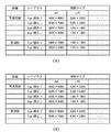
図14(A)(B)は、この印刷する矩形領域の画素数を記憶しているテーブルデータの一例を示す図である。このテーブルは、ROM3101或はRAM3102に記憶されている。またこのテーブルは、機種に依存する情報を含む場合もあるため、複数のテーブルが存在する場合もある。
FIGS. 14A and 14B are diagrams showing an example of table data storing the number of pixels of the rectangular area to be printed. This table is stored in the
図14(A)は、プリンタの機種名が「Model A」であるプリンタにおける、印刷に使用する紙種、印刷レイアウト及び用紙サイズにに対応して、印刷する最大画素数を規定したテーブルのデータ例を示している。また図14(B)は、プリンタの機種名が「Model B」であるプリンタにおける、印刷に使用する紙種、印刷レイアウト及び用紙サイズにに対応して、印刷する最大画素数を規定したテーブルのデータ例を示している。 FIG. 14A shows data of a table that defines the maximum number of pixels to be printed corresponding to the paper type, print layout, and paper size used for printing in the printer whose model name is “Model A”. An example is shown. FIG. 14B is a table that defines the maximum number of pixels to be printed corresponding to the paper type, print layout, and paper size used for printing in the printer whose model name is “Model B”. An example of data is shown.
例えば、機種名が「Model A」のプリンタで、A4の普通紙に1−upで縁なしで印刷する場合は、2400×3300画素が印刷されるのに対して、機種名が「Model B」のプリンタで、A4の普通紙に1−upで縁なしで印刷する場合は、4800×6600画素が印刷される事がわかる。 For example, when a printer with the model name “Model A” is printed on 1-up plain paper on A4 with no border, 2400 × 3300 pixels are printed, whereas the model name is “Model B”. When printing on A4 plain paper with 1-up and no borders, it can be seen that 4800 × 6600 pixels are printed.
このようにステップS73では、ステップS71で取得した「情報1」を用いて、PDプリンタ1000に対応する印刷矩形画素数情報テーブル(例えば図14(A)又は(B))を決定し、同じく「情報2」を用いて、その印刷矩形画素数情報テーブルから所望の画素数を求める。この検索により、例えば「情報1」から「Model A」が判明し、「情報2」から「写真用紙」、「A4」、「1up−縁あり」が得られると、この場合の印刷矩形画素数は「4800×6600」であると分かる。尚、この印刷矩形画素数情報テーブルの構成についても本例に限らず他の情報を含めることが可能であることは言うまでもない。
As described above, in step S73, the “
次にステップS74で、ステップS72,73で取得したプリンタの印刷可能最大画素数と印刷矩形画素数から、画像データのリサイズが必要か否かを判定する。リサイズが必要と判断した場合はステップS75に進み、RAM3102のリサイズフラグにオン(「1」)に設定するとともに、その縮小率を求めてRAM3102に保持しておく。一方ステップS74で、リサイズが不要と判定した場合はステップS76に進み、リサイズフラグをオフ(「0」)に設定する。
Next, in step S74, it is determined whether or not resizing of the image data is necessary from the maximum number of printable pixels and the number of print rectangular pixels acquired in steps S72 and 73. If it is determined that resizing is necessary, the process proceeds to step
図15は、図10のステップS74における、リサイズが必要か否かを判定する処理の詳細を説明するフローチャートである。 FIG. 15 is a flowchart for explaining the details of the process for determining whether or not resizing is necessary in step S74 of FIG.
ステップS91で、印刷対象の画像データの長辺画素数と、PDプリンタ1000における印刷矩形の長辺画素数とを比較する。画像データの長辺画素数の方が大きい場合はリサイズ処理が必要となるため図10のステップS75に進む。一方、画像データの長辺画素数が矩形の長辺画素数以下である場合は、画像データの長辺についてはリサイズ処理が不要であるためステップS92に進む。ステップS92では、短辺について同様の比較を行う。ここで画像データの短辺画素数の方が、PDプリンタ1000における印刷矩形の短辺画素数よりも大きい場合はリサイズ処理が必要となるため、図10のステップS75に進む。一方、画像データの短辺画素数が、印刷矩形領域の短辺画素数以下である場合にはリサイズ処理が不要であるためステップS93に進み、これ以降は、画像データのサイズとプリンタにおける印刷可能最大画素数とを比較する。
In step S91, the number of long side pixels of the image data to be printed is compared with the number of long side pixels of the print rectangle in the
まずステップS93で、画像データの横方向の画素数と、横方向の印刷可能最大画素数とを比較する。ここで画像データの横方向の画素数の方が大きい場合はリサイズ処理が必要となるため図10のステップS75に進む。一方、画像データの横方向の画素数が横方向の印刷可能最大画素数以下である場合にはリサイズ処理が不要であるためステップS94に進み、画像データの縦方向の画素数と、縦方向の印刷可能最大画素数とを比較する。画像データの縦方向の画素数の方が大きい場合はリサイズ処理が必要となるため、図10のステップS75に進む。一方、画像データの縦方向の画素数が縦方向の印刷可能最大画素数以下である場合にはリサイズ処理が不要であるため、図10のステップS76に進む。以上がステップS74で行われる判定処理の詳細である。 First, in step S93, the number of pixels in the horizontal direction of the image data is compared with the maximum number of printable pixels in the horizontal direction. Here, when the number of pixels in the horizontal direction of the image data is larger, resizing processing is necessary, and the process proceeds to step S75 in FIG. On the other hand, if the number of pixels in the horizontal direction of the image data is less than or equal to the maximum number of pixels that can be printed in the horizontal direction, the resizing process is unnecessary, and the process proceeds to step S94. The maximum number of printable pixels is compared. If the number of pixels in the vertical direction of the image data is larger, resizing processing is necessary, and the process proceeds to step S75 in FIG. On the other hand, when the number of pixels in the vertical direction of the image data is equal to or smaller than the maximum number of printable pixels in the vertical direction, the resizing process is unnecessary, and the process proceeds to step S76 in FIG. The above is the details of the determination process performed in step S74.
こうしてステップS75或はS76を実行するとステップS77に進み、レイアウト情報を取得する。 When step S75 or S76 is executed in this way, the process proceeds to step S77 to acquire layout information.
図16(A)〜(D)は、本実施の形態に係るレイアウト情報テーブルと、そのレイアウトを説明する図で、このレイアウト情報テーブルは、ROM3101或はRAM3102に設けられている。また、このレイアウト情報テーブルは機種依存の情報を含む場合もあるため、複数のレイアウト情報テーブルが存在する場合もある。
FIGS. 16A to 16D are diagrams for explaining the layout information table according to the present embodiment and its layout. The layout information table is provided in the
図16(A)は、機種「Model A」のレイアウト情報テーブル例を示し、図16(B)は、機種「Model A」においてレイアウトされて印刷される画像の向き、及び用紙の搬送方向を説明している。 FIG. 16A shows an example of the layout information table of the model “Model A”, and FIG. 16B explains the orientation of the image laid out and printed by the model “Model A” and the paper transport direction. is doing.
同様に図16(C)は、機種「Model B」のレイアウト情報テーブル例を示し、図16(D)は、機種「Model B」においてレイアウトされて印刷される画像の向き、及び用紙の搬送方向を説明している。 Similarly, FIG. 16C shows an example of the layout information table of the model “Model B”, and FIG. 16D shows the orientation of the image laid out and printed by the model “Model B” and the paper transport direction. Is explained.
これにより、用紙の搬送方向が、印刷された画像の上下方向に対応していることがわかる。即ち、機種「Model A」では、いずれの用紙サイズでも、2−up以外は縦長の画像(portrait)であるのに対し、機種「Model B」では、いずれの用紙サイズでも、2−up以外は横長の画像(landscape)である。 As a result, it can be seen that the paper transport direction corresponds to the vertical direction of the printed image. That is, in the model “Model A”, a vertical image (portrait) other than 2-up is used in any paper size, whereas in the model “Model B”, any paper size other than 2-up is used. This is a landscape image.
これによりステップS77では、ステップS71で取得した「情報1」を用いてPDプリンタ1000のレイアウト情報テーブル(例えば図16(A)又は(C))を決定し、同じく「情報2」を用いて、そのレイアウト情報テーブル内を検索する。この検索により、例えば機種「Model A」であれば図16(A)のテーブルを参照して、「情報2」により用紙サイズ「A4」、レイアウト「1−up」等に対応する、印刷矩形の形状をPortrait(縦長矩形)として取得する。尚、この図16(A)(C)に示すレイアウト情報の構成についても本例に限らず他の情報を含めることが可能であることは言うまでもない。
Accordingly, in step S77, the layout information table (for example, FIG. 16A or 16C) of the
次にステップS78で、ステップS77で取得したレイアウト情報に基づいて、画像データの回転が必要か否かを判定する。回転が必要と判定した場合はステップS79に進むが、必要でないと判定した場合はステップS81に進み、回転フラグにオフ(「0」)に設定して処理を終了する。例えば、画像データが横長の画像を表しており、そのサイズが縦4800/横6400の場合に、印刷レイアウトが縦長(Portrait)であれば画像データの矩形形状(横長矩形)と印刷矩形の形状(縦長矩形)とが異なるため、画像データの回転が必要であると判定する。 Next, in step S78, it is determined whether or not image data needs to be rotated based on the layout information acquired in step S77. If it is determined that rotation is necessary, the process proceeds to step S79. If it is determined that rotation is not necessary, the process proceeds to step S81, where the rotation flag is set to off (“0”), and the process ends. For example, when the image data represents a horizontally long image and the size is 4800 vertical / 6400 horizontal, and the print layout is portrait (Portrait), the rectangular shape (horizontal rectangle) of the image data and the print rectangular shape ( Therefore, it is determined that the image data needs to be rotated.
ステップS79では、回転後の画像データのサイズが、PDプリンタ1000の印刷可能な最大画素数を超えないかを判定する。この時リサイズフラグがオン(「1」)に設定されている場合は、RAM3102に保持している縮小率に従ってリサイズ、回転した画像データのサイズと印刷可能な最大画素数とを比較する。回転した画像データのサイズが印刷可能な最大画素数を超えないと判定した場合はステップS80に進み、回転フラグをオン(「1」)に設定して処理を終了する。一方ステップS79で、印刷可能な最大画素数を超えると判定した場合はステップS81に進み、回転フラグをオフ(「0」)に設定して処理を終了する。ここで回転フラグをオフに設定するのは、画像データを回転することで画像データのサイズが印刷可能な最大画素数を超えて、PDプリンタ1000で印刷できなくなることを防ぐためである。
例えば、リサイズフラグがオフに設定されていて、元の画像データのサイズが縦4800画素/横6400画素であり、PDプリンタ1000における印刷可能な最大画素数が縦4800画素/横6400画素の場合、この画像データを時計回りに90度回転すると、この画像データのサイズは縦6400画素/横4800画素に変更する。これにより、画像データの縦サイズ(6400画素)が、PDプリンタ1000の縦方向の印刷可能最大4800画素を超えてしまい、PDプリンタ1000では印刷できなくなる。よってこの場合は、回転フラグをオフにして、縦4800画素/横6400画素の画像データとして処理する。
In step S79, it is determined whether the size of the rotated image data exceeds the maximum number of pixels that can be printed by the
For example, when the resize flag is set to OFF, the size of the original image data is 4800 pixels vertically / 6400 pixels horizontally, and the maximum number of pixels that can be printed by the
尚、以上の説明において、DSC3012は、プリンタのデバイス情報などの「情報1」及びCapabilityを取得し、そのプリンタの有する機能に応じたUIを構築して表示し、そのUIに基づいてDSC3012のユーザが設定した情報として「情報2」を取得してメモリに記憶しておき、これら「情報1」と「情報2」のうちの少なくとも1つからプリンタにおいて印刷可能な最大画素数情報を取得し、これら情報に基づいて、印刷するべき画像データを作成してプリンタに送信することができる。これにより、DSCからプリンタに送信する画像データの量や画像データのフォーマットを、プリンタにおける印刷条件に合致したものとすることができるため、プリンタにおける画像データの処理に要する負荷を軽減でき、また画像データの処理に際してプリンタで使用されるメモリ容量を少なくできる。
In the above description, the
また、プリンタでの用紙サイズや印刷フォーマット等に応じて、前もって画像データを縮小してプリンタに送信するため、画像データの送信に要する時間を減少することができる。 Further, since the image data is reduced and transmitted to the printer in advance according to the paper size, print format, and the like in the printer, the time required for transmitting the image data can be reduced.
更に、DSCはプリンタの印刷可能な最大画素数を知ることができるため、画像データのサイズが印刷可能な最大画素数よりも大きい場合には、前もって画像データを縮小してからプリンタに送信することができる。また、画像データを回転することにより、その画像データのサイズがプリンタの印刷可能な最大画素数を超える場合には、その画像データを回転しないようにしてプリンタに送信するため、画像データを回転することにより、その画像が印刷できなくなるという不具合を防止できる。 Further, since the DSC can know the maximum number of pixels that can be printed by the printer, if the size of the image data is larger than the maximum number of pixels that can be printed, the image data should be reduced before being sent to the printer. Can do. If the image data size exceeds the maximum number of printable pixels of the printer by rotating the image data, the image data is transmitted to the printer without being rotated, so the image data is rotated. As a result, it is possible to prevent a problem that the image cannot be printed.
以上説明したように本実施の形態1によれば、以下のような効果がある。
(1)DSC3012において画像データの回転、リサイズ等の処理を行った後、PDプリンタ1000に、その画像データを送信するため、PDプリンタ1000では特別で高価な画像処理機能を設ける必要が無く、かつ画像処理が簡略化できる。これにより高速に印刷が可能となる。
(2)DSC3012で画像処理を施した画像ファイルを作成する際に、PDプリンタ1000から取得する機能情報に基づいたUIをDSC3012で作成し、そのUIを使用してユーザが設定した印刷条件に従って印刷を行うため、PDプリンタ1000の印刷機能などを生かした印刷処理を行うことができる。
(3)DSC3012は、PDプリンタ1000の印刷可能な最大画素数を知ることができ、その情報に基づいて画像データのリサイズ、回転等の処理が必要か否かを判定するため、PDプリンタ1000の性能に適した画像ファイルを作成することができる。
(4)またプリンタに送信される画像データは、印刷に使用される画像データだけであるため、カメラからプリンタに無駄なデータが送信されるのを防止できる。またこれによりプリンタのメモリ容量を最小限に抑えることが可能となる。更に、カメラからプリンタへのデータ送信の開始後、最初の画像が印刷されるまでの時間を短縮できるという効果がある。
なお、画像データを回転することで画像データのサイズが印刷可能な最大画素数を超えて、PDプリンタ1000で印刷できなくなる場合に、画像データをリサイズにより縮小することも考えられるが、この場合には当然ながら画質が悪くなってしまう。
したがって、DSC側の設定や、プリンタ側の設定で、高画質優先ではなく、速度優先でプリントしたいと言う設定が予めなされているような場合には、画像データを回転することで画像データの縦横のいずれかが、印刷可能(プリンタが格納可能)な最大画素数を超えていても、リサイズ処理を行って、回転処理をしても格納可能な最大画素数以内の大きさにするのが良いであろう。
この場合に、高画質優先か速度優先かの設定は、例えばDCSでは、印刷太陽を設定するUI上に、優先モードを設定するメニューを設けることで設定可能としても良い。そしてこの優先モードを指定するメニューはいつでも設定可能にしても良い。
しかし、回転処理により画像データの縦横のいずれかが、印刷可能(プリンタが格納可能)な最大画素数を超えてしまう場合に表示させるようにすると、画質を落としてしまうような設定をなるべくさせないことが出来、さらに満足度は高いであろう
なぜなら、最大画素数を超えるような画像データを扱うユーザは、もともと高画質嗜好が強いことが大いに考えられるからである。
[実施の形態2]
次に本発明の実施の形態2について説明する。尚、この実施の形態2に係るDSC3012及びPDプリンタ1000のハードウェア構成は前述の実施の形態1と同様であるため、その説明を省略する。また本発明の実施の形態2に係るデジタルカメラ(DSC)3012とPDプリンタ1000との間で通信を行って、DSC3012からPDプリンタ1000に画像データを供給して印刷を行う場合の処理は前述の実施の形態1と同様であるため、前述の図6を引用し、その説明を省略する。更に本発明の実施の形態2に係るDSC3012における画像ファイルの作成処理についても、前述の実施の形態1と同様であるため、前述の図9を引用し、その説明を省略する。
As described above, the first embodiment has the following effects.
(1) Since the image data is transmitted to the
(2) When creating an image file subjected to image processing by the
(3) The
(4) Since the image data transmitted to the printer is only the image data used for printing, it is possible to prevent unnecessary data from being transmitted from the camera to the printer. This also makes it possible to minimize the memory capacity of the printer. Furthermore, there is an effect that it is possible to shorten the time from the start of data transmission from the camera to the printer until the first image is printed.
Note that if the size of the image data exceeds the maximum number of pixels that can be printed by rotating the image data, and the
Therefore, if the setting on the DSC side or the setting on the printer side is set to print with priority on speed instead of priority on high quality, the image data can be rotated vertically and horizontally by rotating the image data. Even if any of the above exceeds the maximum number of pixels that can be printed (the printer can store), it is preferable to perform resizing processing so that the size is within the maximum number of pixels that can be stored even if rotation processing is performed. Will.
In this case, for example, in DCS, setting whether to give priority to high image quality or speed may be set by providing a menu for setting the priority mode on the UI for setting the print sun. The menu for specifying the priority mode may be set at any time.
However, if any of the vertical and horizontal image data is displayed when the maximum number of pixels that can be printed (printer can be stored) exceeds the maximum due to the rotation process, the setting that will reduce the image quality should be avoided as much as possible. It is possible that the user who handles the image data exceeding the maximum number of pixels has a strong preference for high image quality.
[Embodiment 2]
Next, a second embodiment of the present invention will be described. Note that the hardware configurations of the
図17は、本実施の形態2に係るDSC3012におけるリサイズフラグ、回転フラグの設定処理(図9のステップS42)を説明するフローチャートである。図において、前述の図10と共通する処理には同じ記号を付して、その説明を省略する。
FIG. 17 is a flowchart for explaining the resizing flag / rotation flag setting process (step S42 in FIG. 9) in the
ステップS79において、回転後の画像データのサイズが、PDプリンタ1000の印刷可能な最大画素数を超えると判定した場合はステップS101に進み、RAM3102のリサイズフラグをオフ(「0」)に設定するとともに、回転後の画像データのサイズが、PDプリンタ1000における印刷可能な最大画素数内に収まるように、その画像データを縮小するための縮小率を求める。そしてその求めた縮小率をRAM3102に記憶すしてステップS80に進む。ここでは例えば、リサイズフラグ画オフに設定されており、元の画像データのサイズが縦4800画素/横6400画素で、PDプリンタ1000の印刷可能な最大画素数が縦4800画素/横6400画素の場合を考える。この場合、画像を回転しない場合には、その画像データのサイズは印刷可能領域に収容できるので問題はない。しかし、例えば画像データを時計回りに90度回転すると指定されると、回転後の画像データのサイズは縦6400画素/横4800画素となり、縦方向の印刷可能な最大画素数である4800画素を超えてしまう。そこで、このような場合には、リサイズフラグをオン(「1」)に設定し、縮小率を「3/4」(=4800/6400)に設定する。こうして画像の回転及びリサイズを行った後の画像データのサイズは、縦4800画素、横3600画素となり、印刷可能な最大画素数内に収めることができる。
If it is determined in step S79 that the size of the rotated image data exceeds the maximum number of pixels that can be printed by the
以上説明したように本実施の形態2によれば、画像データを回転することにより、その画像データのサイズがプリンタが印刷可能な最大画素数を超えてしまう場合でも、回転後の画像データのサイズを、その印刷可能な最大画素数内に収まるように縮小してプリンタに画像データを供給できる。このため、常にプリンタの印刷条件に合致した印刷用の画像データを作成して供給できるのでプリンタにおける処理の負荷を軽減させて高速で高画質な印刷が可能となる。 As described above, according to the second embodiment, even when the image data is rotated, the size of the image data after the rotation exceeds the maximum number of pixels that can be printed by the printer. Can be reduced so as to be within the maximum number of pixels that can be printed, and image data can be supplied to the printer. For this reason, it is possible to always create and supply image data for printing that matches the printing conditions of the printer, thereby reducing the processing load on the printer and enabling high-speed and high-quality printing.
[実施の形態3]
次に本発明の実施の形態3について説明する。この実施の形態3では、印刷可能な最大画素数情報をプリンタから取得して印刷する場合について説明する。尚、この実施の形態3に係るDSC3012及びPDプリンタ1000のハードウェア構成は前述の実施の形態1と同様であるため、その説明を省略する。また本発明の実施の形態3に係るデジタルカメラ(DSC)3012とPDプリンタ1000との間で通信を行って、DSC3012からPDプリンタ1000に画像データを供給して印刷を行う場合の処理は前述の実施の形態1と同様であるため、前述の図6を引用し、その説明を省略する。更に、本発明の実施の形態3に係るDSC3012における画像ファイルの作成処理についても前述の実施の形態1と同様であるため、前述の図9を引用し、その説明を省略する。
[Embodiment 3]
Next, a third embodiment of the present invention will be described. In the third embodiment, a case will be described in which information about the maximum number of pixels that can be printed is acquired from a printer and printed. Note that the hardware configurations of the
図18は、本実施の形態3の特徴であるPDプリンタ1000からDSC3012に送信されるCapability情報を示したschemaの一例を示す図である。このCapability情報は、図6のステップS22で、PDプリンタ1000からDSC3012に送信される。このschemaでは、行702に、PDプリンタ1000が印刷可能な最大画像サイズ(maxSupportSizes)が記述されている。
FIG. 18 is a diagram illustrating an example of schema indicating Capability information transmitted from the
<maxSupportSizes> FBAA19CB FBAB12C0
は、最大画像サイズの情報を表している。
<MaxSupportSizes> FBAA19CB FBAB12C0
Represents the maximum image size information.
このschemaはステップS3でDSC3012により受信され、これを受信したDSC3012は、PDプリンタ1000とDSC3012との間で予め取り決めている事項に従って、<maxSupportSizes>の行702に含まれる情報がPDプリンタ1000において印刷可能な最大画像サイズを表していると認識する。行702の2つの8桁の文字列のそれぞれにおいて、上位4桁は画像の方向(縦/横)を示し、下位4桁は実際の印刷サイズを16進法で示している。上位4桁の「FBAA」は横方向を示し、「FBAB」は縦方向を示している。そして縦方向の下位4桁「19CB」は10進数の「6400」に該当している。また横方向の下位4桁の「12C0」は10進数の「4800」に相当している。従って、この場合は、PDプリンタ1000における印刷可能な最大画素数は、縦方向が6400画素で、横方向が4800画素であることが分かる。
This schema is received by the
図19は、本発明の実施の形態3に係るDSC3012におけるリサイズフラグ、回転フラグの設定処理(図9のステップS42)を説明するフローチャートである。図において、前述の図10と共通する処理には同じ記号を付して、その説明を省略する。
FIG. 19 is a flowchart for explaining the resizing flag / rotation flag setting process (step S42 in FIG. 9) in the
ステップS111では、ステップS71でRAM3102に記憶した「情報1」と「情報2」を取得する。ここで「情報1」は、例えば図11に示すデバイス情報であり、例えばVendor名、プリンタ名、Version情報等が含まれている。また「情報2」は、例えば図12に示すような、ユーザにより設定された情報であり、例えば用紙サイズ、紙種、レイアウト、縁あり/なしの情報等が含まれている。また「情報1」「情報2」のいずれかには、上述したCapability情報で取得した印刷可能な最大画素数情報も含まれている。
In step S111, “
そして、印刷可能な最大画素数の情報を記憶するテーブルを作成する。このテーブルは、例えば前述の図13に示すような、印刷可能な最大画素数の情報を記憶しているテーブルと同じである。尚、ここでは、このテーブルを構成する要素は、上述したCapability情報で取得した印刷可能な最大画素数である。また、この作成したテーブルはRAM3102に格納される。その他の処理については、本実施の形態1の図10のフローチャートと同様であるため、その説明を省略する。
Then, a table for storing information on the maximum number of pixels that can be printed is created. This table is the same as a table that stores information on the maximum number of pixels that can be printed, for example, as shown in FIG. Here, the element constituting this table is the maximum number of printable pixels acquired by the Capability information described above. The created table is stored in the
以上説明したように本実施の形態3によれば、DSC3012は印刷可能な画素数をPDプリンタ1000から取得して、画像データのリサイズや回転が必要であるかを判定することが可能である。
As described above, according to the third embodiment, the
また、印刷可能な画素数を、プリンタから取得できない場合は、DSC3012に前もって記憶している情報を基に、前述の実施の形態1と同様に印刷することも可能であることは言うまでもない。
Needless to say, if the number of printable pixels cannot be obtained from the printer, printing can be performed in the same manner as in the first embodiment based on information stored in advance in the
更に、印刷矩形情報、レイアウト情報も前述のCapability情報に含めても良く、DSC3012はこれら情報を予め記憶しておく代わりに、PDプリンタ1000からのCapability情報に基づいて判定しても良い。
Further, print rectangle information and layout information may be included in the aforementioned Capability information, and the
以上説明したように本実施の形態3によれば、DSCに前もって印刷特性情報や印刷機能を記憶していないプリンタが接続された場合にでも、そのプリンタからのCapability情報により、プリンタに出力する画像データのリサイズ、回転が必要か否かを判定して、そのプリンタに適した画像処理を実行することができる。またこうして処理された画像データがプリンタに送信されて印刷されるため、プリンタの処理の負荷を軽減して高速で印刷が可能となる。 As described above, according to the third embodiment, even when a printer that does not store print characteristic information or print function in advance is connected to the DSC, an image to be output to the printer based on Capability information from the printer. It is possible to determine whether it is necessary to resize or rotate data, and to perform image processing suitable for the printer. In addition, since the processed image data is transmitted to the printer for printing, the processing load of the printer is reduced and printing can be performed at high speed.
[他の実施の形態]
本発明の目的は前述したように、実施の形態の機能を実現するソフトウェアのプログラムコードを記録した記憶媒体をシステム或は装置に提供し、そのシステム或は装置のコンピュータ(又はCPUやMPU)が記憶媒体に格納されたプログラムコードを読み出し実行することによっても達成される。この場合、記憶媒体から読み出されたプログラムコード自体が前述した実施形態の機能を実現することになり、そのプログラムコードを記憶した記憶媒体は本発明を構成することになる。このようなプログラムコードを供給するための記憶媒体としては、例えば、フロッピィ(登録商標)ディスク、ハードディスク、光ディスク、光磁気ディスク、CD−ROM,CD−R、磁気テープ、不揮発性のメモリカード、ROMなどを用いることができる。
[Other embodiments]
As described above, the object of the present invention is to provide a system or apparatus with a storage medium storing software program codes for realizing the functions of the embodiment, and the computer of the system or apparatus (or CPU or MPU) is provided. It is also achieved by reading and executing the program code stored in the storage medium. In this case, the program code itself read from the storage medium realizes the functions of the above-described embodiments, and the storage medium storing the program code constitutes the present invention. As a storage medium for supplying such a program code, for example, a floppy (registered trademark) disk, hard disk, optical disk, magneto-optical disk, CD-ROM, CD-R, magnetic tape, nonvolatile memory card, ROM Etc. can be used.
またコンピュータが読み出したプログラムコードを実行することにより、前述した実施の形態の機能が実現されるだけでなく、そのプログラムコードの指示に基づき、コンピュータ上で稼動しているOS(オペレーティングシステム)などが実際の処理の一部又は全部を行い、その処理によって前述した実施の形態の機能が実現される場合も含まれる。 Further, by executing the program code read by the computer, not only the functions of the above-described embodiments are realized, but also an OS (operating system) operating on the computer based on the instruction of the program code. This includes a case where part or all of the actual processing is performed and the functions of the above-described embodiments are realized by the processing.
更に、記憶媒体から読み出されたプログラムコードが、コンピュータに挿入された機能拡張ボードやコンピュータに接続された機能拡張ユニットに備わるメモリに書きこまれた後、そのプログラムコードの指示に基づき、その機能拡張ボードや機能拡張ユニットに備わるCPUなどが実際の処理の一部又は全部を行い、その処理によって前述した実施の形態の機能が実現される場合も含む。 Furthermore, after the program code read from the storage medium is written in the memory provided in the function expansion board inserted into the computer or the function expansion unit connected to the computer, the function is determined based on the instruction of the program code. This includes the case where the CPU of the expansion board or function expansion unit performs part or all of the actual processing, and the functions of the above-described embodiments are realized by the processing.
Claims (11)
印刷装置との通信開始に応じて、前記印刷装置との通信プロトコルのバージョンに関する情報を取得する取得手段と、
印刷対象の画像ファイルを指定する指定手段と、
前記印刷対象の画像ファイルの画像データを回転する回転手段と、
前記回転手段により回転させた画像データを前記印刷装置へ送信する送信手段と、
前記取得手段により取得した通信プロトコルのバージョンに基づいて、前記指定手段で指定された前記印刷対象の画像ファイルの画像データを前記回転手段により回転させるか否かを決定する決定手段と、
を有することを特徴とする画像供給デバイス。 An image supply device that communicates with a printing apparatus using a predetermined communication protocol and supplies image data to the printing apparatus,
An acquisition means for acquiring information relating to a version of a communication protocol with the printing apparatus in response to the start of communication with the printing apparatus;
And designating means for designating the image file to be printed,
Rotating means for rotating the image data of the image file of the print subject,
Transmitting means for transmitting the image data rotated by the rotating means to the printing apparatus;
Determining means for determining whether to rotate the image data of the image file to be printed designated by the designation means based on the version of the communication protocol obtained by the obtaining means ;
An image supply device comprising:
前記印刷ジョブにより印刷対象となっている画像ファイルのファイル情報を要求するファイル情報要求を前記印刷装置から受信したことに応じて、当該ファイル情報を前記印刷装置に送信するファイル情報送信手段とを有し、File information transmission means for transmitting the file information to the printing apparatus in response to receiving from the printing apparatus a file information request for requesting file information of the image file to be printed by the print job. And
前記回転手段により前記印刷対象の画像ファイルの画像データを回転させる場合には、前記ファイル情報送信手段は、前記ファイル情報要求で要求された前記ファイルのファイル情報ではなく、前記回転手段により画像データを回転させた画像ファイルのファイル情報を送信することを特徴とする請求項1乃至4のいずれか1項に記載の画像供給デバイス。When rotating the image data of the image file to be printed by the rotating means, the file information transmitting means sends the image data by the rotating means instead of the file information of the file requested by the file information request. The image supply device according to any one of claims 1 to 4, wherein file information of the rotated image file is transmitted.
前記決定手段は、前記通信プロトコルのバージョンと前記印刷設定画面で設定された印刷条件とに応じて、前記印刷対象の画像ファイルの画像データを前記回転手段により回転させるか否かを決定することを特徴とする請求項1乃至5のいずれか1項に記載の画像供給デバイス。The determination unit determines whether to rotate the image data of the image file to be printed by the rotation unit according to the version of the communication protocol and the print condition set on the print setting screen. The image supply device according to claim 1, wherein the image supply device is an image supply device.
画像データをリサイズするリサイズ手段とを更に有し、
前記優先指定手段により前記速度優先が指定されており、前記印刷対象の画像ファイルの画像データを前記回転手段により回転させた後の画像データの縦横の画素数が、前記通信プロトコルのバージョンに対応する縦横の画素数を越える場合には、前記リサイズ手段によるリサイズ処理と前記回転手段による回転処理を行うことを特徴とする請求項2乃至6のいずれか1項に記載の画像供給デバイス。 And the priority designation means for designating whether the velocity priority or image quality priority,
Further comprising a resizing means for resizing the image data,
The priority designation means the speed priority is specified, the number of vertical and horizontal pixels of the image data after the image data is rotated by the rotation means of the image file of the print target, it corresponds to the version of the communication protocol The image supply device according to any one of claims 2 to 6 , wherein when the number of vertical and horizontal pixels is exceeded, the resizing process by the resizing unit and the rotating process by the rotating unit are performed.
印刷装置との通信開始に応じて、前記印刷装置との通信プロトコルのバージョンに関する情報を取得する取得工程と、
印刷対象の画像ファイルを指定する指定工程と、
前記印刷対象の画像ファイルの画像データを回転する回転工程と、
前記回転工程で回転させた画像データを前記印刷装置へ送信する送信工程と、
前記取得工程で取得した通信プロトコルのバージョンに基づいて、前記指定工程で指定された前記印刷対象の画像ファイルの画像データを前記回転工程で回転させるか否かを決定する決定工程と、
を有することを特徴とする画像供給デバイスの制御方法。 A method for controlling an image supply device that communicates with a printing apparatus using a predetermined communication protocol and supplies image data to the printing apparatus,
An acquisition step in response to communication start of the printing apparatus, to obtain information about the version of the communication protocol with the printing device,
A specification process for specifying an image file to be printed;
A rotation step of rotating the image data of the image file of the print subject,
A transmission step of transmitting the image data rotated in the rotation step to the printing apparatus;
A determination step of determining whether to rotate the image data of the image file to be printed specified in the specification step based on the version of the communication protocol acquired in the acquisition step ;
An image supply device control method comprising:
当該コンピュータを、The computer
印刷装置との通信開始に応じて、前記印刷装置との通信プロトコルのバージョンに関する情報を取得する取得手段と、An acquisition means for acquiring information relating to a version of a communication protocol with the printing apparatus in response to the start of communication with the printing apparatus;
印刷対象の画像ファイルを指定する指定手段と、A designation means for designating an image file to be printed;
前記印刷対象の画像ファイルの画像データを回転する回転手段と、Rotating means for rotating image data of the image file to be printed;
前記回転手段により回転させた画像データを前記印刷装置へ送信する送信手段と、Transmitting means for transmitting the image data rotated by the rotating means to the printing apparatus;
前記取得手段で取得した通信プロトコルのバージョンに基づいて、前記指定手段で指定された前記印刷対象の画像ファイルの画像データを前記回転手段で回転させるか否かを決定する決定手段と、を有する画像供給デバイスとして機能させるためのプログラム。Determining means for determining whether or not to rotate the image data of the image file to be printed designated by the designation means based on the version of the communication protocol obtained by the obtaining means; Program to function as a supply device.
Priority Applications (2)
| Application Number | Priority Date | Filing Date | Title |
|---|---|---|---|
| JP2004267513A JP4468120B2 (en) | 2004-09-14 | 2004-09-14 | Image supply device, method for controlling the device, program thereof, and storage medium |
| US11/221,518 US7907291B2 (en) | 2004-09-14 | 2005-09-08 | Image supply device and control method of the same and printing system |
Applications Claiming Priority (1)
| Application Number | Priority Date | Filing Date | Title |
|---|---|---|---|
| JP2004267513A JP4468120B2 (en) | 2004-09-14 | 2004-09-14 | Image supply device, method for controlling the device, program thereof, and storage medium |
Publications (3)
| Publication Number | Publication Date |
|---|---|
| JP2006085296A JP2006085296A (en) | 2006-03-30 |
| JP2006085296A5 JP2006085296A5 (en) | 2007-10-04 |
| JP4468120B2 true JP4468120B2 (en) | 2010-05-26 |
Family
ID=36033555
Family Applications (1)
| Application Number | Title | Priority Date | Filing Date |
|---|---|---|---|
| JP2004267513A Expired - Fee Related JP4468120B2 (en) | 2004-09-14 | 2004-09-14 | Image supply device, method for controlling the device, program thereof, and storage medium |
Country Status (2)
| Country | Link |
|---|---|
| US (1) | US7907291B2 (en) |
| JP (1) | JP4468120B2 (en) |
Families Citing this family (11)
| Publication number | Priority date | Publication date | Assignee | Title |
|---|---|---|---|---|
| US8215556B2 (en) * | 2004-06-28 | 2012-07-10 | Konica Minolta Laboratory U.S.A., Inc. | Color barcode producing, reading and/or reproducing method and apparatus |
| US7669769B2 (en) | 2005-03-28 | 2010-03-02 | Konica Minolta Systems Laboratory, Inc. | Systems and methods for preserving and maintaining document integrity |
| US20060274357A1 (en) * | 2005-06-03 | 2006-12-07 | Zhongming Shen | Systems and methods for digital image printing |
| JP2007082162A (en) * | 2005-09-16 | 2007-03-29 | Toshiba Corp | Digital camera and method for transmitting image information |
| JP4725336B2 (en) * | 2006-01-30 | 2011-07-13 | ブラザー工業株式会社 | Image processing apparatus and image processing program |
| KR20080066226A (en) * | 2007-01-11 | 2008-07-16 | 삼성전자주식회사 | Image forming device, host device and direct printing controlling method thereof |
| JP2010061448A (en) * | 2008-09-04 | 2010-03-18 | Canon Inc | Image processing apparatus, its controlling method, and program |
| CN103029458B (en) * | 2011-09-30 | 2015-11-25 | 北大方正集团有限公司 | For digital printed control system and method |
| JP6051722B2 (en) * | 2012-09-20 | 2016-12-27 | ブラザー工業株式会社 | Program and information processing apparatus |
| US20190126651A1 (en) * | 2017-10-26 | 2019-05-02 | Toshiba Tec Kabushiki Kaisha | Printer apparatus, printing method, and computer readable medium |
| JP7181701B2 (en) * | 2018-04-13 | 2022-12-01 | キヤノン株式会社 | Information processing device, printing device, control method and program thereof |
Family Cites Families (13)
| Publication number | Priority date | Publication date | Assignee | Title |
|---|---|---|---|---|
| JP3510342B2 (en) | 1994-07-20 | 2004-03-29 | オリンパス株式会社 | Camera system |
| US6111605A (en) * | 1995-11-06 | 2000-08-29 | Ricoh Company Limited | Digital still video camera, image data output system for digital still video camera, frame for data relay for digital still video camera, data transfer system for digital still video camera, and image regenerating apparatus |
| JP3747108B2 (en) * | 1996-02-02 | 2006-02-22 | キヤノン株式会社 | Digital imaging apparatus and control method thereof |
| US7212229B2 (en) | 1997-04-04 | 2007-05-01 | Eastman Kodak Company | Digital camera providing image processing for an attachable printer |
| US6940541B1 (en) | 1997-04-04 | 2005-09-06 | Eastman Kodak Company | Printer parameter compensation by a host camera |
| JPH11339026A (en) | 1998-05-28 | 1999-12-10 | Canon Inc | Recording controller and recording control method |
| US7123367B1 (en) * | 1998-08-31 | 2006-10-17 | Seiko Epson Corporation | Printing apparatus |
| JP3360625B2 (en) | 1998-11-30 | 2002-12-24 | 村田機械株式会社 | Document reading and recording device |
| US6668319B1 (en) * | 2000-04-04 | 2003-12-23 | Hewlett-Packard Development Company, L.P. | Method and mechanism for correlating and matching mutually supported protocol features of system devices |
| JP2003134457A (en) | 2001-10-29 | 2003-05-09 | Fuji Photo Film Co Ltd | Electronic camera |
| JP4136817B2 (en) | 2002-08-05 | 2008-08-20 | キヤノン株式会社 | Digital camera and printer |
| JP2004320277A (en) * | 2003-04-15 | 2004-11-11 | Sony Corp | Printing terminal, printing system, storage medium, and program |
| JP4250543B2 (en) * | 2004-02-06 | 2009-04-08 | キヤノン株式会社 | Imaging apparatus, information processing apparatus, and control method thereof |
-
2004
- 2004-09-14 JP JP2004267513A patent/JP4468120B2/en not_active Expired - Fee Related
-
2005
- 2005-09-08 US US11/221,518 patent/US7907291B2/en not_active Expired - Fee Related
Also Published As
| Publication number | Publication date |
|---|---|
| US7907291B2 (en) | 2011-03-15 |
| JP2006085296A (en) | 2006-03-30 |
| US20060055953A1 (en) | 2006-03-16 |
Similar Documents
| Publication | Publication Date | Title |
|---|---|---|
| KR100738493B1 (en) | Image supply device and control method thereof and printing system | |
| US7929172B2 (en) | Image supply device, control method of the device, and printing system | |
| US7907291B2 (en) | Image supply device and control method of the same and printing system | |
| JP3496009B2 (en) | Recording apparatus, control method therefor, and program | |
| JP4968888B2 (en) | Printing system, imaging apparatus, control method therefor, program, and storage medium | |
| US20060039020A1 (en) | Image supply device, control method thereof and printing system | |
| JP2004072350A (en) | Digital camera and printer | |
| JP4926644B2 (en) | Recording apparatus, recording method, and program | |
| JP4343858B2 (en) | Printing system, printing apparatus, printing method, and image processing apparatus | |
| JP4709246B2 (en) | Image supply device, method for controlling the device, and printing system | |
| JP2008073882A (en) | Direct print system | |
| JP4350615B2 (en) | Image supply device, method for controlling the device, and printing system | |
| JP4612822B2 (en) | Image supply device, method for controlling the device, and printing system | |
| JP2006086587A (en) | Image supplying device, method of controlling the same, and printing system | |
| JP4566733B2 (en) | Image processing apparatus and method | |
| JP2006060593A (en) | Image supply device, control method of the device, and print system | |
| JP2006086588A (en) | Image supply device, control method of the device, and print system | |
| JP5241933B2 (en) | Imaging apparatus and control method thereof, printing system, program, and storage medium | |
| JP2007004715A (en) | Image supply device, control method of this device and printing system | |
| JP2005066987A (en) | Recorder, recording system, and its controlling method | |
| JP2004180031A (en) | Recording apparatus |
Legal Events
| Date | Code | Title | Description |
|---|---|---|---|
| A521 | Request for written amendment filed |
Free format text: JAPANESE INTERMEDIATE CODE: A523 Effective date: 20070822 |
|
| A621 | Written request for application examination |
Free format text: JAPANESE INTERMEDIATE CODE: A621 Effective date: 20070822 |
|
| RD03 | Notification of appointment of power of attorney |
Free format text: JAPANESE INTERMEDIATE CODE: A7423 Effective date: 20070822 |
|
| A977 | Report on retrieval |
Free format text: JAPANESE INTERMEDIATE CODE: A971007 Effective date: 20091127 |
|
| A131 | Notification of reasons for refusal |
Free format text: JAPANESE INTERMEDIATE CODE: A131 Effective date: 20091204 |
|
| A521 | Request for written amendment filed |
Free format text: JAPANESE INTERMEDIATE CODE: A523 Effective date: 20100128 |
|
| TRDD | Decision of grant or rejection written | ||
| A01 | Written decision to grant a patent or to grant a registration (utility model) |
Free format text: JAPANESE INTERMEDIATE CODE: A01 Effective date: 20100219 |
|
| A01 | Written decision to grant a patent or to grant a registration (utility model) |
Free format text: JAPANESE INTERMEDIATE CODE: A01 |
|
| A61 | First payment of annual fees (during grant procedure) |
Free format text: JAPANESE INTERMEDIATE CODE: A61 Effective date: 20100224 |
|
| R150 | Certificate of patent or registration of utility model |
Ref document number: 4468120 Country of ref document: JP Free format text: JAPANESE INTERMEDIATE CODE: R150 Free format text: JAPANESE INTERMEDIATE CODE: R150 |
|
| FPAY | Renewal fee payment (event date is renewal date of database) |
Free format text: PAYMENT UNTIL: 20130305 Year of fee payment: 3 |
|
| FPAY | Renewal fee payment (event date is renewal date of database) |
Free format text: PAYMENT UNTIL: 20140305 Year of fee payment: 4 |
|
| LAPS | Cancellation because of no payment of annual fees |