JP4465834B2 - Combine - Google Patents

Combine Download PDF

Info

Publication number
JP4465834B2
JP4465834B2 JP2000249562A JP2000249562A JP4465834B2 JP 4465834 B2 JP4465834 B2 JP 4465834B2 JP 2000249562 A JP2000249562 A JP 2000249562A JP 2000249562 A JP2000249562 A JP 2000249562A JP 4465834 B2 JP4465834 B2 JP 4465834B2
Authority
JP
Japan
Prior art keywords
transfer cylinder
transfer
cylinder
spiral
grain
Prior art date
Legal status (The legal status is an assumption and is not a legal conclusion. Google has not performed a legal analysis and makes no representation as to the accuracy of the status listed.)
Expired - Fee Related
Application number
JP2000249562A
Other languages
Japanese (ja)
Other versions
JP2002058330A (en
JP2002058330A5 (en
Inventor
浩二 泉
武 水本
純二 土居原
伸 二神
Current Assignee (The listed assignees may be inaccurate. Google has not performed a legal analysis and makes no representation or warranty as to the accuracy of the list.)
Iseki and Co Ltd
Original Assignee
Iseki and Co Ltd
Priority date (The priority date is an assumption and is not a legal conclusion. Google has not performed a legal analysis and makes no representation as to the accuracy of the date listed.)
Filing date
Publication date
Application filed by Iseki and Co Ltd filed Critical Iseki and Co Ltd
Priority to JP2000249562A priority Critical patent/JP4465834B2/en
Publication of JP2002058330A publication Critical patent/JP2002058330A/en
Publication of JP2002058330A5 publication Critical patent/JP2002058330A5/ja
Application granted granted Critical
Publication of JP4465834B2 publication Critical patent/JP4465834B2/en
Anticipated expiration legal-status Critical
Expired - Fee Related legal-status Critical Current

Links

Images

Landscapes

  • Threshing Machine Elements (AREA)

Description

【0001】
【発明の属する技術分野】
この発明は、穀粒排出装置を備えたコンバインに関するものである。
【0002】
【従来の技術】
コンバインで立毛穀稈を収穫するときには、このコンバインの前部に設けた刈取機で刈取りした刈取り穀稈は、この刈取機で移送され、後部に設けた脱穀機へ供給され、この脱穀機で脱穀され、脱穀済みの穀粒は、揚穀装置で揚送されて穀粒貯留タンク内へ供給され、この穀粒貯留タンク内で一時貯留される。
【0003】
貯留した穀粒を機外へ排出するときは、穀粒貯留タンク内の穀粒は、この穀粒貯留タンクから縦移送筒内へ供給され、この縦移送筒に内装した縦移送螺旋から後移送筒内へ移送供給され、この後移送筒に内装した後移送螺旋で前移送筒内へ移送供給され、この前移送筒に内装した前移送螺旋で引継ぎされて移送され、この前移送筒の前端部に設けた排出筒の下部の排穀口から機外へ排出される。
【0004】
又、前記コンバインを納屋内へ収納するとき、又は路上走行のとき、及び圃場間を移動走行するときには、作業者が操縦席から一度おりて、前移送筒を回動操作して折り畳み、後移送筒の横側へこの前移送筒を位置させて収納状態にして、納屋への収納、及び収穫作業中以外の時の走行を行う。
【0005】
【発明が解決しようとする課題】
後移送筒の前端部に設けた前移送筒を回動操作して、折り畳み状態、又は作業状態にするときには、操縦席に搭乗した作業者は、一度この操縦席からおりて、回動操作をしないと、折り畳み状態、又は作業状態にすることができなく、このために、これらの操作がめんどうであったが、この発明により、この問題を解決しようとするものである。
【0006】
【課題を解決するための手段】
このために、請求項1記載の発明は、車台(2)の下側に走行装置(3)を設け、該車台(2)の前側に刈取機(13)を昇降自在に設け、該車台(2)の上側に脱穀機(12)を設け、該脱穀機(12)の右側に穀粒貯留タンク(5)を設け、該穀粒貯留タンク(5)の前方の部位に操縦席(18b)を設け、穀粒貯留タンク(5)の底部に穀粒を後方へ移送する底部移送螺旋(14a)を設け、該底部移送螺旋(14a)によって移送された穀粒を引き継いで移送する縦移送筒(6)を穀粒貯留タンク(5)の後側に設け、該縦移送筒(6)の上端部に設けた継手メタル(23)に第1移送螺旋(7)を内装した第1移送筒(8)を取り付け、該第1移送筒(8)の端部に設けた回動受メタル(28)の横側部に第1孔(28b)を設け、第2移送螺旋(9)を内装する第2移送筒(10)の端部に設けた回動メタル(30)の横側部に第2孔(30a)を設け、該第1孔(28b)と第2孔(30a)に支持軸(33)を挿入して第1移送筒(8)と第2移送筒(10)とを折り畳み自在に接続し、第2移送筒(10)の外周部下側の所定位置に前挿入孔(37a)を備えた前側の前受板(37)と後挿入孔(38a)を備えた後側の後受板(38)を固着し、該第2移送筒(10)を折り畳んで第1移送筒(8)の横側に収納する際に操縦席(18b)上から回動操作する丸棒状の回動ハンドル(11)を、前挿入孔(37a)と後挿入孔(38a)に挿入して引き出し状態及び収納状態に前後移動自在に第2移送筒(10)側に支持し、該第2移送筒(10)を折り畳んで第1移送筒(8)の横側に収納した状態において、前記回動ハンドル(11)を収納状態に操作すると該回動ハンドル(11)の握り部(39)が前記回動メタル(30)から突出しない構成とし、前記第1移送筒(8)の外周の横一側部に固着した支持受具(35a)に、下方へ折曲した折曲部(36a)を先端部に有し第2移送筒(10)を折り畳んで第1移送筒(8)の横側に収納するときに該第2移送筒(10)の外周下部を受ける略L字形状の案内ガイド(36)を設けたことを特徴とするコンバインとしたものである。
【0007】
請求項2記載の発明は、前記第2移送筒(10)に結合ピン(10a)を固着し、支持受具(35a)には挿入孔(35c)を設け、第2移送筒(10)を折り畳むときに、該第2移送筒(10)が案内ガイド(36)で案内されて結合ピン(10a)が挿入孔(35c)へ挿入される構成としたことを特徴とする請求項1記載のコンバインとしたものである。
【0008】
【0009】
【0010】
【0011】
【0012】
【発明の効果】
請求項1記載の発明によると、第1移送筒に折り畳み自在に設けた第2移送筒10に、該第2移送筒10を折り畳んで第1移送筒の横側に収納する際に回動操作する回動ハンドル11、第2移送筒(10)の外周部下側の所定位置に固着した前側の前受板(37)の前挿入孔(37a)と後側の後受板(38)の後挿入孔(38a)に挿入して引き出し状態及び収納状態に前後移動自在に支持したことにより、作業者が操縦席18b上から操作可能な操作力の軽い折り畳み用の回動ハンドル11を構成することができた。しかも、この回動ハンドル(11)を収納状態に操作すると、回動ハンドル(11)の握り部(39)が第2移送筒(10)の端部に設けた回動メタル(30)から突出しないので、コンバインの機体を覆う機体カバーの着脱時に、この回動ハンドル11が障害物になりにくく、この機体カバーの破損を少なくすることができる。
【0013】
また、第1移送筒(8)の外周の横一側部に固着した支持受具(35a)に、下方へ折曲した折曲部(36a)を先端部に有し第2移送筒(10)を折り畳んで第1移送筒(8)の横側に収納するときに該第2移送筒(10)の外周下部を受ける略L字形状の案内ガイド(36)を設けたことにより、第2移送筒(10)の折り畳み操作が容易となる。
【0014】
請求項2記載の発明によると、上記請求項1記載の発明の効果に加えて、第2移送筒(10)が案内ガイド(36)と結合ピン(10a)との両者で支持されるため、該第2移送筒(10)の支持が確実となる。
【0015】
【発明の実施の形態】
以下、本発明の一実施例を図面に基づいて説明する。
コンバイン1の走行装置3の上側に設けた走行車台(車台)2の上側に載置した脱穀機12の右横側に装着した穀粒貯留タンク5内に貯留した穀粒を機外へ排出する穀粒排出装置である縦移送螺旋6aを内装した縦移送筒6の上端部側には、後移送螺旋(第1移送螺旋)7を内装した後移送筒(第1移送筒)8と、この後移送筒8の前端部に前移送螺旋(第2移送螺旋)9を内装した折り畳み自在な前移送筒(第2移送筒)10とを設け、この前移送筒10の下側には、回動ハンドル11を設け、これら前・後移送筒10、8、及び回動ハンドル11等を主に図示して説明する。
【0016】
前記コンバイン1の走行車台2の下側には、図14で示す如く土壌面を走行する左右一対の走行クローラ4を張設した走行装置3を配設し、走行車台2の上側には、脱穀機12を載置した構成である。走行車台2の前側の刈取機13で立毛穀稈を刈取りし、この刈取り穀稈はこの刈取機13で移送され、脱穀機12のフィードチエン12aと挟持杆12bとで引継ぎ挟持移送して脱穀し、脱穀済みで選別済みの穀粒を回収して一時貯留する穀粒貯留タンク5は、脱穀機12の右横側に装着した構成である。穀粒貯留タンク5へ穀粒の供給は、脱穀機12の右横側に設けた揚穀装置27により、供給する構成である。
【0017】
前記脱穀機12の前部で走行車台2の前側には、図14で示す如く前端位置から立毛穀稈を分離するナローガイド15a、及び分草体15bと、この分離された穀稈を引起す引起装置16aと、引起された穀稈を掻込み移送する掻込移送装置17aと、掻込された穀稈を刈取る刈刃装置16bと、刈取り穀稈を移送して、脱穀機12のフィードチエン12aと挟持杆12bとへ受渡しする穀稈移送装置17bとを設けてなる刈取機13は、油圧駆動による伸縮シリンダ13aにより、土壌面に対して昇降自在に作用させる構成である。
【0018】
前記脱穀機12側には、図14で示す如くコンバイン1を始動、停止、及び各部を調節等の操作を行う操作装置18aと、これらの操作を行う作業者が搭乗する操縦席18bとを設け、この操縦席18bの下側で、走行車台2の上側には、エンジン18cを載置すると共に、後方部には、穀粒貯留タンク5を配設する。これら走行装置3と、脱穀機12と、刈取機13と、エンジン18c等により、コンバイン1の機体1aを構成している。
【0019】
前記刈取機13の穀稈移送装置17bによって形成される穀稈移送経路中には、刈取られて移送される穀稈に接触作用することにより、脱穀機12へ穀稈の供給の有無を検出する穀稈センサ13bを設けた構成である。走行車台2の前端部に装架された走行用のミッションケース19aの伝動経路中には、その出力回転数に基づく走行車速を検出する車速センサ19bを設けた構成である。
【0020】
前記穀粒貯留タンク5内の底部には、貯留穀粒を後方部へ移送する前後移送螺旋(底部移送螺旋)14aを前後方向に設けると共に、後方へ移送される穀粒を引継ぎして、継手ケース14bを介して方向変換する縦移送螺旋6aを内装した縦移送筒6を略垂直姿勢で回動可能に、継手ケース14bの上側で穀粒貯留タンク5の後側に設けた構成である。
【0021】
前記縦移送筒6の上端部には、上端部を支点として、その全長がコンバイン1の前後長に亘り折畳み自在、上下回動自在、旋回自在で穀粒を機外へ排出する折畳穀粒移送装置20を設けた構成である。
前記操作装置18aの表面板18dの外側面には、図13で示す如く折畳穀粒移送装置20を主として操作する各種スイッチ、及び各種操作レバー等を図示して説明する。折畳穀粒移送装置20を上下回動、及び左右旋回操作するオーガレバー21aと、エンジン18cの動力をこの折畳穀粒移送装置20へ伝達する籾排出レバー21bとを設け、この籾排出レバー21bを排出位置へ操作すると、穀粒貯留タンク5内の穀粒を機外へ排出できる構成である。
【0022】
又、前記折畳穀粒移送装置20等を始動、及び停止させるときに操作するON−OFFスイッチ方式のスイッチ22aと、旋回させるときに操作するON−OFFスイッチ方式の旋回スイッチ22bと、ON−OFFスイッチ方式のランプスイッチ22cとを設けた構成である。
【0023】
前記縦移送筒6の上端部に設けた継手メタル23の前側には、図2〜図4、及び図6で示す如く後移送螺旋7を内装した後移送筒8を設けた構成である。
前記継手メタル23は、図6で示す如く縦メタル24aと横メタル24bとよりなる構成であり、これら縦・横メタル24a、24b内には、図6で示す如く引継螺旋25と、この引継螺旋25の移送終端に固着した移送羽根25aとを設けると共に、後移送螺旋7の後螺旋軸7aの移送始端部と、後受ブッシュ7fとの間に亘る外径部には、始端螺旋26を固着して設けた構成である。
【0024】
前記縦移送筒6へ供給されて、縦移送螺旋6aで移送される穀粒は、継手メタル23内の引継螺旋25から、始端螺旋26、及び後移送筒8内の後移送螺旋7へと順次引継ぎされて、移送される構成である。
前記筒形状の後移送筒8は、図5、及び図6で示す如くL字形状の継手メタル23の前側に固着して設け、この後移送筒8の前端部には、ベアリング28aを内装した回動受メタル28を固着して設け、この回動受メタル28の一方側の横側部には、受孔28bを設けた構成である。該ベアリング28aの内径部には、先端部にクラッチ爪29aを設け、後側の外径部が六角形状の後螺旋補助軸29を挿入して軸支した構成である。
【0025】
前記後移送筒8内には、図5、及び図6で示す如く後移送螺旋7を内装した構成である。この後移送螺旋7はパイプ形状の後螺旋軸7aの外径部に後螺旋プレート7bを固着すると共に、前端の内径部には、内径が六角形状の受ブッシュ7cを挿入して固着し、後端の内径部には、内径が六角形状の後受ブッシュ7fを挿入して固着した構成である。
【0026】
前記後移送螺旋7の受ブッシュ7cは、回動受メタル28に設けた後螺旋補助軸29へ挿入して軸支すると共に、後受ブッシュ7fは、継手メタル23の横メタル24bの後受軸7dへ挿入して軸支し、この後移送螺旋7を回転自在に軸支した構成である。
【0027】
前記筒形状の前移送筒10は、図1〜図5、及び図7、図8で示す如く後端部に回動メタル30を固着して設けると共に、前端部に排出筒31を装着して設けた構成である。回動メタル30の一方側の横側部には、受孔(第2孔)30aを設け、この受孔30aと回動受メタル28の受孔(第1孔)28bとには、支持軸33を挿入して、この前移送筒10と、後移送筒8とを接続させた構成である。この前移送筒10の固定は後移送筒8の外周部に固着したコ字形状の支持枠32に固定用ハンドル32aを挿入して装着し、この固定用ハンドル32aを回動操作し、前移送筒10の回動メタル30の突出部30bへ結合させて、これら回動メタル30と回動受メタル28とを締付けする構成である。
【0028】
前記回動メタル30には、ベアリング30cを内装して設け、このベアリング30cには、先端部にクラッチ爪34aを設けた前螺旋補助軸34を挿入して軸支した構成である。
前記前移送筒8内には、図5で示す如く前移送螺旋9を内装した構成である。この前移送螺旋9はパイプ形状の前螺旋軸9aの外径部に前螺旋プレート9bを固着すると共に、後端の内径部には、内径が六角形状の受ブッシュ9cを挿入して固着し、又、前端の内径部には、前受軸9dを挿入して固着した構成である。回動受メタル28の後螺旋補助軸29のクラッチ爪29aと、前螺旋補助軸34のクラッチ爪34aとが噛合し、この前移送螺旋9と、後移送螺旋7とが同時に回転駆動する構成である。
【0029】
前記前移送螺旋9の受ブッシュ9cは、回動メタル30に設けた前螺旋補助軸34へ挿入すると共に、前受軸9dは排出筒31の前側壁板31aの内側面に設けた受メタル31cへ挿入し、この前移送螺旋9を回転自在に軸支した構成である。該前移送螺旋9で移送された穀粒は、排出筒31の下部の排穀口31bより、機外へ排出される構成である。
【0030】
前記回動受メタル28と回動メタル30との締付けは、固定用ハンドル32a以外に、図7で示す如く締付用孔28c、30dを設けて、ボルト、及びナット等により装着した構成である。
前記後移送筒8の外径の一方側の横側には、図7、及び図8で示す如く支持装置35を設け、この支持装置35のコ字形状の支持受具35aを固着して設け、この支持受具35aには、ゴム材、又は樹脂材等よりなるクッション部材35bを設けると共に、挿入孔35cを設けた構成である。保持受具35aの先端の下側には、前移送筒10を回動操作して折畳みしたときに、この前移送筒10の外径下部を受ける略L字形状で先端部が下方へ折曲した折曲部36aを設けた案内ガイド36を固着して設けた構成である。
【0031】
前記案内ガイド36は前移送筒10を保持したときは、該前移送筒10の中心位置(イ)から折曲部36aまでの間(L)は、前移送筒10へ固着した結合ピン10aの全長(L1)より、大きくした構成である。この前移送筒10を折畳み操作のときに、この案内ガイド36でこの前移送筒10が案内されて、結合ピン10aが保持受具35の挿入孔35cへ容易に挿入可能な構成であると共に、この前移送筒10を確実に保持する構成であり、又、この結合ピン10aには、抜け止め用のヘヤーピン10bを挿入した構成である。この案内ガイド36には、クッション部材35bを複数個設けた構成である。
【0032】
前記案内ガイド36を設けたことにより、前移送筒10の折畳み操作が容易であり、又、この案内ガイド36と結合ピン10aとの両者で支持されることにより、支持が確実である。更に持受具35aと案内ガイド36とには、クッション部材35aを設けたことにより、前移送筒10へ傷が付くことを防止できる構成である。
【0033】
前記前移送筒10の外径部には、図1〜図4で示す如くこの前移送筒10を折り畳んで、後移送筒8の横側へ収納状態にするときに、回動操作する回動ハンドル11を設け、低価格で操作力の軽い折り畳み機構にした構成である。
前記回動ハンドル11は丸棒材よりなる構成であり、図1〜図4で示す如く前移送筒10の外周部の下側で、所定位置の前後両側には、前・後受板37、38を固着して設けた構成であり、該前・後受板37、38の前・後挿入孔37a,38aへ挿入して前後移動自在で引き出し状態、及び収納状態に支持した構成である。この回動ハンドル11の前後両端部には、ゴム材、又は樹脂材等よりなる把り39を挿入した構成である。前移送筒10を収納状態に操作したときには、回動ハンドル11も収納状態に操作する構成であり、このときには、この回動ハンドル11の把り39部(握り部39)が前移送筒10の回動メタル30の前側面より突出しない構成である。
【0034】
前記前移送筒10の下側に設けた回動ハンドル11の引出し、及び収納操作は、作業者が操縦席18b上より、操作可能な構成である。
前記回動ハンドル11の外周部には、ゴム材、又は樹脂材等よりなる弾性材の固定装置40を挿入して設けた構成である。該固定装置40には、挿入孔40aを設け、この挿入孔40aは前受板37に固着して設けた固定ピン41の頭部41aの前側へ挿入して、回動ハンドル11の前後操作時以外のときの前後移動を防止する構成である。回動ハンドル11を操作するときには、固定装置40の挿入孔40aを固定ピン41から取り出しする構成である。又、固定装置40の着脱操作は、作業者が操縦席18b上より、操作が可能な構成である。
【0035】
前記回動ハンドル11は前移送筒10の下側に前後移動自在に設けて、作業者が操縦席18bに座ったままで操作できると共に、コンバイン1を圃場へ一時放置するときに、機体1aを覆う機体カバー(図示せず)の着脱時に障害物になることなく、又、この機体カバーの破損を防止する構成である。
【0036】
前記回動ハンドル11に固定装置40を設けて、この回動ハンドル11が自然に前後移動することを防止した構成である。
収納状態の前記前移送筒10を穀粒を排出状態に回動操作するときは、結合ピン10aへ挿入したヘヤーピン10bを抜き、回動受メタル28と回動メタル30とを接合させた固定用ハンドル32aを回動して、結合を解放させると共に、固定装置40を取り外しする。
【0037】
その後に、図4で示す如く前移送筒10を作業者が操縦席18b上より、左外方向へ手で押して、後移送筒8に対して略直角状になるまで回動操作した後に、回動ハンドル11を引き出し、この回動ハンドル11で回動操作して、前移送筒10を後移送筒8へ接合状態に操作する構成であり、その後に固定用ハンドル32aにより、これら前・後移送筒10、8を接合する。その後にヘヤーピン10bを挿入すると共に、回動ハンドル11を収納状態に操作して、固定装置40で固定する構成である。
【0038】
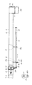
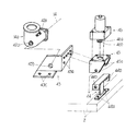
前記穀粒貯留タンク5の後側には、図9〜図12で示す如くこの穀粒貯留タンク5に内装した前後移送螺旋14aの移送終端部を受けて、穀粒の移送方向を上方部へと変更する継手ケース14aを設け、この継手ケース14aの右横側には、複数個の取付ネジ孔42aと、後側には、位置固定ボス42bを設けると共に、継手ケース14aの上側面には、縦移送筒6を回動自在に装着した構成である。この回転により、前・後移送筒10、8が左右に旋回する構成である。
【0039】
前記継手ケース14aには、図12で示す如く取付台43の横側の取付孔43a部は、継手ケース14aの取付ネジ孔42a部へボルト等で装着した構成であり、又、取付台43の後側のボス孔43bは、継手ケース14aの後側の位置固定ボス42b部へ挿入すると共に、後側の取付孔43c部は、走行車台2の上側面へボルト、及びナット等で装着した構成である。
【0040】
モータ受台44は、図12で示す如く下側部に下取付孔44aを設け、この下取付孔44a部は、継手ケース14bの右側で、走行車台2の上側面へボルト、及びナット等で装着した構成である。上側部の左右両側には、モータ取付台45を装着する上取付孔44bを設けた構成である。
【0041】
正逆回転する旋回用モータ46は、図12で示す如くモータ取付台45の上側面へボルト、及びナット等で装着した構成であり、旋回用モータ46の変速用のモータ軸46aの下部の軸端部には、ギヤー46bを軸支した構成である。
前記モータ取付台45の前後両側の取付孔45a,45aと、モータ受台44の上取付孔44b,44bとは、ボルト、及びナット等で装着した構成である。
【0042】
前記縦移送筒6に設けたギヤー6bと、旋回用モータ46のギヤー46bとは、図10で示す如く噛合する構成であり、旋回用モータ46の回転駆動により、縦移送筒6は左、又は右へ回転する構成である。
前記旋回用モータ46の取付部以外の前・後移送筒10、8をユニットとして、他機種に使用することができることにより、コスト低減が可能であり、又、旋回用モータ46は継手ケース14bの右横側に設けたことにより、従来の後側に設けたものに対して、コンバイン1の前後長を大幅に短くすることができて、大幅なコスト低減ができると共に、右側より、旋回用モータ46部のチエックを容易に行うことができる。
【図面の簡単な説明】
【図1】 回動ハンドル部の拡大側面図
【図2】 前移送筒部の作用拡大平面図
【図3】 前移送筒部の収納状態時の拡大平面図
【図4】 前移送筒部の作用拡大平面図
【図5】 前・後移送筒の接合部の拡大平断面図
【図6】 後移送筒と縦移送筒との接合部の拡大平断面図
【図7】 案内ガイド部の拡大正面図
【図8】 案内ガイド部の拡大平面図
【図9】 旋回用モータ部の拡大平面図
【図10】 旋回用モータ取付部の拡大正面図
【図11】 旋回用モータ取付部の拡大平面図
【図12】 旋回用モータ取付部の拡大背面斜視図
【図13】 操作装置部の拡大背面斜視図
【図14】 コンバインの全体側側面図
【符号の説明】
2 走行車台(車台)
3 走行装置
5 穀粒タンク
6 縦移送筒
7 後移送螺旋(第1移送螺旋)
8 後移送筒(第1移送筒)
9 前移送螺旋(第2移送螺旋)
10 前移送筒(第2移送筒)
10a 結合ピン
11 回動ハンドル
12 脱穀機
13 刈取機
14a 前後移送螺旋(底部移送螺旋)
18b 操縦席
23 継手メタル
28 回動受メタル
28b 受孔(第1孔)
30 回動メタル
30a 受孔(第2孔)
31b 排穀
33 支持軸
35a 支持受具
35c 挿入孔
36 案内ガイド
36a 折曲部
37 前受板
37a 前挿入孔
38 後受板
38a 後挿入孔
39 把り部(握り部)
[0001]
BACKGROUND OF THE INVENTION
The present invention relates to a combine equipped with a grain discharging device.
[0002]
[Prior art]
When harvesting napped cereals with a combine, the harvested cereals harvested by a reaper provided at the front of the combine are transported by the reaper, supplied to a threshing machine provided at the rear, and threshed by the thresher. Then, the threshed grain is lifted by the whipping device, supplied into the grain storage tank, and temporarily stored in the grain storage tank.
[0003]
When discharging the stored grain out of the machine, the grain in the grain storage tank is supplied from the grain storage tank into the vertical transfer cylinder, and then transferred from the vertical transfer spiral built in the vertical transfer cylinder. After being transported and supplied into the cylinder, and then transported and supplied into the front transport cylinder by the rear transport spiral installed in the transport cylinder, transferred and transferred by the front transport spiral installed in the front transport cylinder, the front end of the front transport cylinder It is discharged out of the machine through the shed at the bottom of the discharge tube provided in the section.
[0004]
Also, when storing the combine in the storage room, when traveling on the road, and when traveling between fields, the operator is once from the cockpit, and the front transfer cylinder is rotated to be folded and rear transferred. The front transfer cylinder is positioned on the side of the cylinder to be in the storage state, and stored in the barn and travels at times other than during the harvesting operation.
[0005]
[Problems to be solved by the invention]
When turning the front transfer cylinder provided at the front end of the rear transfer cylinder to the folded state or working state, the operator who has boarded the cockpit is once out of this cockpit and performs the rotation operation. Otherwise, it cannot be in the folded state or the working state, and for this reason, these operations have been troublesome. However, the present invention intends to solve this problem.
[0006]
[Means for Solving the Problems]
For this purpose, the invention described in claim 1 is provided with a traveling device (3) below the chassis (2), a reaper (13) is provided on the front side of the chassis (2) so as to be movable up and down, and the chassis ( 2) the upper threshing machine (12) provided in, grain storage tank (5) provided on the right side of the dehydration grain (12), ahead of the site cockpit of該穀grain storage tank (5) (18b ), A bottom transfer spiral (14a) for transferring the grain backward is provided at the bottom of the grain storage tank (5), and the vertical transfer for transferring the grain transferred by the bottom transfer spiral (14a) 1st transfer which provided the pipe | tube (6) in the rear side of the grain storage tank (5), and was equipped with the 1st transfer spiral (7) in the joint metal (23) provided in the upper end part of this vertical transfer cylinder (6). A cylinder (8) is attached, and a first hole (28b) is provided on the lateral side of the rotation receiving metal (28) provided at the end of the first transfer cylinder (8). A second hole (30a) is provided on the lateral side of the rotating metal (30) provided at the end of the second transfer cylinder (10) that houses the second transfer spiral (9), and the first hole (28b). The support shaft (33) is inserted into the second hole (30a) to foldably connect the first transfer cylinder (8) and the second transfer cylinder (10), and below the outer peripheral portion of the second transfer cylinder (10) . A front receiving plate (37) provided with a front insertion hole (37a) and a rear receiving plate (38) provided with a rear insertion hole (38a) are fixedly attached to a predetermined position on the side, and the second transfer cylinder When the folding handle (10) is folded and stored on the side of the first transfer cylinder (8), a round bar-shaped turning handle (11) that is turned from the cockpit (18b) is connected to the front insertion hole (37a). supporting the rear insertion hole and inserted into (38a) back and forth in the extended state and the stored state movably second transfer cylinder (10) side, the second transfer cylinder (10) folded In a state where the housing on the side of the first transfer cylinder (8), said grip portion (39) of said rotating metal (30) of the pivoting handle (11) when the operating to the retracted state the pivoting handle (11) The support receiving tool (35a) fixed to the lateral one side of the outer periphery of the first transfer cylinder (8) has a bent portion (36a) bent downward at the tip. 2 A substantially L-shaped guide guide (36) is provided for receiving the lower part of the outer periphery of the second transfer cylinder (10) when the transfer cylinder (10) is folded and stored on the side of the first transfer cylinder (8) . It is a combine characterized by that.
[0007]
According to the second aspect of the present invention, the coupling pin (10a) is fixed to the second transfer cylinder (10), the support holder (35a) is provided with an insertion hole (35c), and the second transfer cylinder (10) is provided. The second transfer cylinder (10) is guided by a guide guide (36) and the coupling pin (10a) is inserted into the insertion hole (35c) when folded. It is a combine.
[0008]
[0009]
[0010]
[0011]
[0012]
【The invention's effect】
According to the first aspect of the invention, the second transfer cylinder which is provided foldably to the first transfer cylinder (8) (10), first transfer cylinder folded second transfer cylinder (10) (8) A front insertion hole (37a) of a front receiving plate (37) in which a rotation handle ( 11 ) that rotates when stored in the lateral side is fixed to a predetermined position below the outer peripheral portion of the second transfer cylinder (10). ) And the rear receiving plate (38) of the rear side receiving plate (38) and supported so as to be movable back and forth in the pulled out and retracted state, so that the operator can operate from the cockpit ( 18b ). It was possible to construct a folding handle ( 11 ) for folding with a light operating force. Moreover, when the rotating handle (11) is operated to the retracted state, the grip portion (39) of the rotating handle (11) protrudes from the rotating metal (30) provided at the end of the second transfer cylinder (10). Therefore, when the body cover that covers the combine body is attached or detached, the rotating handle ( 11 ) is less likely to become an obstacle, and the damage to the body cover can be reduced.
[0013]
Further, the support holder (35a) fixed to the lateral one side portion of the outer periphery of the first transfer cylinder (8) has a bent portion (36a) bent downward at the distal end portion, and the second transfer cylinder (10). ) Is folded and stored on the side of the first transfer cylinder (8), the second transfer cylinder (10) is provided with a substantially L-shaped guide guide (36) that receives the lower outer periphery of the second transfer cylinder (10). The folding operation of the transfer cylinder (10) is facilitated.
[0014]
According to the invention of claim 2, in addition to the effect of the invention of claim 1, the second transfer cylinder (10) is supported by both the guide guide (36) and the coupling pin (10a). Support of the second transfer cylinder (10) is ensured.
[0015]
DETAILED DESCRIPTION OF THE INVENTION
Hereinafter, an embodiment of the present invention will be described with reference to the drawings.
The grain stored in the grain storage tank 5 mounted on the right side of the threshing machine 12 placed on the upper side of the traveling chassis (chassis) 2 provided on the upper side of the traveling device 3 of the combine 1 is discharged out of the machine. A rear transfer cylinder (first transfer cylinder) 8 with a rear transfer helix (first transfer helix) 7 is provided on the upper end side of the vertical transfer cylinder 6 having a vertical transfer helix 6a, which is a grain discharging device. A foldable front transfer cylinder (second transfer cylinder) 10 having a front transfer helix (second transfer helix) 9 is provided at the front end of the rear transfer cylinder 8. A movable handle 11 is provided, and the front and rear transfer cylinders 10, 8 and the rotary handle 11 will be mainly illustrated and described.
[0016]
A traveling device 3 in which a pair of left and right traveling crawlers 4 traveling on the soil surface is stretched is disposed below the traveling chassis 2 of the combine 1, and threshing is disposed above the traveling chassis 2. In this configuration, the machine 12 is placed. The napped cedar is harvested by the reaper 13 on the front side of the traveling chassis 2, and this reaped cereal is transferred by the reaper 13, and the threshing machine 12 takes over the feed chain 12 a and the clamping ridge 12 b to carry out threshing. The grain storage tank 5 that recovers and temporarily stores the threshed and selected grain is a configuration that is mounted on the right side of the threshing machine 12. The supply of the grain to the grain storage tank 5 is a configuration in which the grain is supplied by a whipping device 27 provided on the right side of the threshing machine 12.
[0017]
As shown in FIG. 14, the narrow guide 15a and the weed body 15b for separating the napped grain buds from the front end position, and the trigger for causing the separated corn straws are formed on the front side of the threshing machine 12 at the front side of the threshing machine 12. A device 16a, a scraping transfer device 17a for scrambling and transporting the raised cereal, a cutting blade device 16b for cutting the squeezed cereal, and a feed chain for the threshing machine 12 The reaping machine 13 provided with the culm transfer device 17b that delivers to 12a and the holding cradle 12b is configured to move up and down freely with respect to the soil surface by a telescopic cylinder 13a that is hydraulically driven.
[0018]
On the threshing machine 12 side, as shown in FIG. 14, an operation device 18a for starting and stopping the combine 1 and adjusting each part and the like, and a cockpit 18b on which an operator who performs these operations board, are provided. The engine 18c is mounted on the lower side of the cockpit 18b and on the upper side of the traveling chassis 2, and the grain storage tank 5 is disposed in the rear part. The traveling device 3, the threshing machine 12, the reaping machine 13, the engine 18c, and the like constitute the body 1a of the combine 1.
[0019]
In the culm transfer path formed by the culm transfer device 17b of the reaper 13, the presence / absence of supply of cereal to the threshing machine 12 is detected by contacting the culm that is harvested and transferred. It is the structure which provided the grain mash sensor 13b. In the transmission path of the traveling mission case 19a mounted on the front end portion of the traveling chassis 2, a vehicle speed sensor 19b for detecting the traveling vehicle speed based on the output rotational speed is provided.
[0020]
At the bottom of the grain storage tank 5, a front / rear transfer spiral (bottom transfer spiral) 14a for transferring the stored grain to the rear part is provided in the front / rear direction. The vertical transfer cylinder 6 having a vertical transfer spiral 6a whose direction is changed via the case 14b is provided on the rear side of the grain storage tank 5 on the upper side of the joint case 14b so as to be rotatable in a substantially vertical posture.
[0021]
The upper end of the vertical transfer cylinder 6 has a folding end that can be folded, swiveled up and down, and swiveled with the upper end as a fulcrum, with the upper end as a fulcrum. In this configuration, a transfer device 20 is provided.
On the outer surface of the surface plate 18d of the operation device 18a, various switches and various operation levers for mainly operating the folded grain transfer device 20 as shown in FIG. 13 will be described. An auger lever 21a for turning the folded grain transfer device 20 up and down and turning left and right and a straw discharge lever 21b for transmitting the power of the engine 18c to the folded grain transfer device 20 are provided. When 21b is operated to the discharge position, the grain in the grain storage tank 5 can be discharged out of the machine.
[0022]
Further, an ON-OFF switch type switch 22a that is operated when starting and stopping the folding grain transfer device 20 and the like, an ON-OFF switch type turning switch 22b that is operated when turning, and an ON- An OFF switch type lamp switch 22c is provided.
[0023]
In the front side of the joint metal 23 provided at the upper end of the vertical transfer cylinder 6, a rear transfer cylinder 8 having a rear transfer spiral 7 is provided as shown in FIGS. 2 to 4 and 6.
The joint metal 23 is composed of a vertical metal 24a and a horizontal metal 24b as shown in FIG. 6, and in these vertical and horizontal metals 24a and 24b, a takeover spiral 25 and this takeover spiral are shown in FIG. The transfer blade 25a fixed to the transfer end of the transfer 25 is provided, and the start end spiral 26 is fixed to the outer diameter portion between the transfer start end of the rear spiral shaft 7a of the rear transfer spiral 7 and the rear receiving bush 7f. It is the structure provided.
[0024]
The grains supplied to the vertical transfer cylinder 6 and transferred by the vertical transfer spiral 6 a are sequentially transferred from the takeover spiral 25 in the joint metal 23 to the start end spiral 26 and the rear transfer spiral 7 in the rear transfer cylinder 8. It is the structure which is taken over and transferred.
The cylindrical rear transfer cylinder 8 is fixedly provided on the front side of the L-shaped joint metal 23 as shown in FIGS. 5 and 6, and a bearing 28 a is provided at the front end of the rear transfer cylinder 8. The rotation receiving metal 28 is fixedly provided, and a receiving hole 28b is provided on one side of the rotation receiving metal 28. A clutch claw 29a is provided at the tip of the inner diameter portion of the bearing 28a, and the rear outer diameter portion is supported by inserting a hexagonal rear spiral auxiliary shaft 29.
[0025]
The rear transfer cylinder 8 has a configuration in which a rear transfer spiral 7 is housed as shown in FIGS. The rear transfer spiral 7 has a rear spiral plate 7b fixed to the outer diameter portion of the pipe-shaped rear spiral shaft 7a, and a hexagonal receiving bush 7c is inserted and fixed to the inner diameter portion of the front end. A hexagonal rear receiving bush 7f is inserted into and fixed to the inner diameter portion of the end.
[0026]
The receiving bush 7c of the rear transfer helix 7 is inserted into and supported by a rear helix auxiliary shaft 29 provided on the rotation receiving metal 28, and the rear receiving bush 7f is a rear receiving shaft of the horizontal metal 24b of the joint metal 23. It is configured to be inserted into 7d and pivotally supported, and then the transfer spiral 7 is pivotally supported.
[0027]
As shown in FIGS. 1 to 5, 7, and 8, the cylindrical front transfer cylinder 10 is provided with a rotating metal 30 fixed to the rear end portion, and a discharge cylinder 31 attached to the front end portion. This is a configuration provided. A receiving hole (second hole) 30a is provided on one side of the rotating metal 30, and a support shaft is provided between the receiving hole 30a and the receiving hole (first hole) 28b of the rotating metal 28. 33 is inserted and the front transfer cylinder 10 and the rear transfer cylinder 8 are connected. The front transfer cylinder 10 is fixed by inserting and attaching a fixing handle 32a to a U-shaped support frame 32 fixed to the outer periphery of the rear transfer cylinder 8, and rotating the fixing handle 32a to perform the front transfer. The rotating metal 30 and the rotation receiving metal 28 are coupled to the projecting portion 30b of the rotating metal 30 of the cylinder 10 and tightened.
[0028]
The rotating metal 30 is provided with a bearing 30c provided therein, and a front spiral auxiliary shaft 34 provided with a clutch pawl 34a at the tip is inserted into and supported by the bearing 30c.
The front transfer cylinder 8 has a structure in which a front transfer spiral 9 is housed as shown in FIG. The front transfer helix 9 has a front spiral plate 9b fixed to the outer diameter portion of the pipe-shaped front spiral shaft 9a, and a hexagonal receiving bush 9c having an inner diameter is inserted and fixed to the inner diameter portion of the rear end. Further, the front receiving shaft 9d is inserted and fixed to the inner diameter portion of the front end. The clutch pawl 29a of the rear spiral auxiliary shaft 29 of the rotation receiving metal 28 and the clutch pawl 34a of the front spiral auxiliary shaft 34 are engaged with each other, and the front transfer spiral 9 and the rear transfer spiral 7 are rotationally driven simultaneously. is there.
[0029]
The receiving bush 9c of the front transfer spiral 9 is inserted into the front spiral auxiliary shaft 34 provided on the rotating metal 30, and the front receiving shaft 9d is provided on the inner side surface of the front side wall plate 31a of the discharge cylinder 31. The front transfer spiral 9 is rotatably supported. The grain transferred by the front transfer spiral 9 is configured to be discharged out of the machine from the grain outlet 31b below the discharge cylinder 31.
[0030]
The rotation receiving metal 28 and the rotation metal 30 are tightened with bolts and nuts provided with tightening holes 28c and 30d as shown in FIG. 7 in addition to the fixing handle 32a. .
A support device 35 is provided on one side of the outer diameter of the rear transfer cylinder 8 as shown in FIGS. 7 and 8, and a U-shaped support receiver 35a of the support device 35 is fixedly provided. The support receiver 35a is provided with a cushion member 35b made of a rubber material, a resin material, or the like, and an insertion hole 35c. Below the tip of the holding receptacle 35a, when the front transfer cylinder 10 is turned and folded, the front end is bent downward in a substantially L shape that receives the lower part of the outer diameter of the front transfer cylinder 10. The guide guide 36 provided with the bent portion 36a is fixedly provided.
[0031]
When the guide guide 36 holds the front transfer cylinder 10, the distance between the center position (A) of the front transfer cylinder 10 and the bent portion 36 a (L) is that of the coupling pin 10 a fixed to the front transfer cylinder 10. It is the structure made larger than full length (L1). When the front transfer cylinder 10 is folded, the front transfer cylinder 10 is guided by the guide guide 36 so that the coupling pin 10a can be easily inserted into the insertion hole 35c of the holding support 35. The front transfer cylinder 10 is configured to be securely held, and a hair pin 10b for retaining is inserted into the coupling pin 10a. The guide guide 36 has a plurality of cushion members 35b.
[0032]
By providing the guide guide 36, the folding operation of the front transfer cylinder 10 is easy, and the support is ensured by being supported by both the guide guide 36 and the coupling pin 10a. More and supporting lifting bracket as 35a and guides 36, by providing a cushion member 35a, a configuration that can prevent the pre-scratched into the transfer tube 10.
[0033]
As shown in FIG. 1 to FIG. 4, the front transfer cylinder 10 is folded at the outer diameter portion of the front transfer cylinder 10 to rotate when the front transfer cylinder 10 is housed in the lateral side of the rear transfer cylinder 8. This is a structure in which a handle 11 is provided and a folding mechanism with a low cost and a light operating force is provided.
The rotating handle 11 is composed of a round bar, and as shown in FIGS. 1 to 4, on the lower side of the outer peripheral portion of the front transfer cylinder 10, on both front and rear sides of a predetermined position, front and rear receiving plates 37, 38 is fixedly provided, and is inserted into the front / rear insertion holes 37a, 38a of the front / rear receiving plates 37, 38 so as to be movable back and forth and supported in a pulled out state and a stored state. A grip 39 made of a rubber material, a resin material, or the like is inserted into both front and rear ends of the rotating handle 11. When the front transfer cylinder 10 is operated to the storage state, the rotation handle 11 is also operated to the storage state. At this time, the grip 39 (grip part 39) of the rotation handle 11 is connected to the front transfer cylinder 10. This is a configuration that does not protrude from the front side surface of the rotating metal 30.
[0034]
The pull-out handle 11 provided at the lower side of the front transfer cylinder 10 and the storage operation can be operated by the operator from the cockpit 18b.
An elastic material fixing device 40 made of a rubber material, a resin material or the like is inserted and provided on the outer peripheral portion of the rotating handle 11. The fixing device 40 is provided with an insertion hole 40a. The insertion hole 40a is inserted into the front side of the head 41a of the fixing pin 41 that is fixedly attached to the front receiving plate 37, so that the rotary handle 11 can be operated back and forth. It is the structure which prevents the back-and-forth movement at the time other than. When operating the rotating handle 11, the insertion hole 40 a of the fixing device 40 is taken out from the fixing pin 41. In addition, the attaching / detaching operation of the fixing device 40 is configured such that the operator can operate from the cockpit 18b.
[0035]
The rotating handle 11 is provided below the front transfer cylinder 10 so as to be movable back and forth so that the operator can operate while sitting on the cockpit 18b, and covers the body 1a when the combine 1 is temporarily left in the field. This is a configuration that prevents the airframe cover from being damaged without being an obstacle when the airframe cover (not shown) is attached or detached.
[0036]
The rotation handle 11 is provided with a fixing device 40 to prevent the rotation handle 11 from moving back and forth naturally.
When the front transfer cylinder 10 in the stored state is rotated to remove the grain, the hair pin 10b inserted into the coupling pin 10a is pulled out, and the rotation receiving metal 28 and the rotation metal 30 are joined. The handle 32a is rotated to release the coupling, and the fixing device 40 is removed.
[0037]
Thereafter, as shown in FIG. 4, the operator manually pushes the front transfer cylinder 10 from above the cockpit 18 b to the left outward direction and rotates it until it becomes substantially perpendicular to the rear transfer cylinder 8. The moving handle 11 is pulled out and rotated by the rotating handle 11 to operate the front transfer cylinder 10 in a joined state to the rear transfer cylinder 8. Thereafter, the front / rear transfer is performed by the fixing handle 32a. The cylinders 10 and 8 are joined. Thereafter, the hair pin 10b is inserted, and the rotating handle 11 is operated to be stored and fixed by the fixing device 40.
[0038]
On the rear side of the grain storage tank 5, as shown in FIGS. 9 to 12, a transfer terminal end of the front / rear transfer spiral 14 a built in the grain storage tank 5 is received, and the grain transfer direction is directed upward. A joint case 14a to be changed is provided, a plurality of mounting screw holes 42a are provided on the right side of the joint case 14a, a position fixing boss 42b is provided on the rear side, and an upper side surface of the joint case 14a is provided. The vertical transfer cylinder 6 is rotatably mounted. By this rotation, the front and rear transfer cylinders 10 and 8 are configured to turn left and right.
[0039]
As shown in FIG. 12, the joint case 14a has a mounting hole 43a portion on the side of the mounting base 43 attached to the mounting screw hole 42a portion of the joint case 14a with a bolt or the like. The rear boss hole 43b is inserted into the position fixing boss 42b on the rear side of the joint case 14a, and the rear mounting hole 43c is mounted on the upper side surface of the traveling chassis 2 with bolts, nuts, and the like. It is.
[0040]
As shown in FIG. 12, the motor cradle 44 is provided with a lower mounting hole 44a on the lower side, and this lower mounting hole 44a is formed on the right side of the joint case 14b with the bolt, nut, etc. It is a configuration that is mounted. On the left and right sides of the upper part, an upper mounting hole 44b for mounting the motor mounting base 45 is provided.
[0041]
As shown in FIG. 12, the turning motor 46 that rotates forward and backward is configured to be mounted on the upper surface of the motor mount 45 with bolts, nuts, and the like, and a shaft below the motor shaft 46a for shifting the turning motor 46. A gear 46b is pivotally supported at the end.
The mounting holes 45a, 45a on both the front and rear sides of the motor mounting base 45 and the upper mounting holes 44b, 44b of the motor receiving base 44 are mounted with bolts, nuts and the like.
[0042]
The gear 6b provided on the vertical transfer cylinder 6 and the gear 46b of the turning motor 46 are meshed as shown in FIG. 10, and the vertical transfer cylinder 6 is turned to the left or It is the structure rotated to the right.
Since the front and rear transfer cylinders 10 and 8 other than the mounting portion of the turning motor 46 can be used as a unit for other models, the cost can be reduced, and the turning motor 46 can be connected to the joint case 14b. By providing it on the right side, the front and rear length of the combine 1 can be greatly shortened compared to what is provided on the rear side of the prior art, and the cost can be greatly reduced. 46 parts can be checked easily.
[Brief description of the drawings]
[Fig. 1] Enlarged side view of the rotating handle portion [Fig. 2] Enlarged plan view of the action of the front transfer cylinder portion [Fig. 3] Enlarged plan view of the front transfer cylinder portion in the storage state [Fig. Action enlarged plan view [Fig. 5] Enlarged plan sectional view of the junction between the front and rear transfer cylinders [Fig. 6] Enlarged plan sectional view of the junction between the rear and vertical transfer cylinders [Fig. 7] Enlargement of the guide guide Front view [Fig. 8] Enlarged plan view of the guide guide unit [Fig. 9] Enlarged plan view of the turning motor unit [Fig. 10] Enlarged front view of the turning motor mounting unit [Fig. 11] Enlarged plan view of the turning motor mounting unit FIG. 12 is an enlarged rear perspective view of the turning motor mounting portion. FIG. 13 is an enlarged rear perspective view of the operating device portion. FIG. 14 is an overall side view of the combine.
2 Running chassis (chassis)
3 traveling device 5 grain tank 6 vertical transfer cylinder 7 rear transfer spiral (first transfer spiral)
8 Rear transfer cylinder (first transfer cylinder)
9 Front transfer spiral (second transfer spiral)
10 Front transfer tube (second transfer tube)
10a coupling pin 11 rotating handle 12 threshing machine 13 reaping machine 14a forward and backward transfer spiral (bottom transfer spiral)
18b Cockpit 23 Joint metal 28 Rotating metal 28b Receiving hole (first hole)
30 Rotating metal 30a Receiving hole (second hole)
31b threshing 33 support shaft
35a support bracket
35c insertion hole
36 guide
36a bent part
37 front backing plate
37a front insertion hole
38 back plate
38a rear insertion hole 39 grip part (grip part)

Claims (2)

車台(2)の下側に走行装置(3)を設け、該車台(2)の前側に刈取機(13)を昇降自在に設け、該車台(2)の上側に脱穀機(12)を設け、該脱穀機(12)の右側に穀粒貯留タンク(5)を設け、該穀粒貯留タンク(5)の前方の部位に操縦席(18b)を設け、穀粒貯留タンク(5)の底部に穀粒を後方へ移送する底部移送螺旋(14a)を設け、該底部移送螺旋(14a)によって移送された穀粒を引き継いで移送する縦移送筒(6)を穀粒貯留タンク(5)の後側に設け、該縦移送筒(6)の上端部に設けた継手メタル(23)に第1移送螺旋(7)を内装した第1移送筒(8)を取り付け、該第1移送筒(8)の端部に設けた回動受メタル(28)の横側部に第1孔(28b)を設け、第2移送螺旋(9)を内装する第2移送筒(10)の端部に設けた回動メタル(30)の横側部に第2孔(30a)を設け、該第1孔(28b)と第2孔(30a)に支持軸(33)を挿入して第1移送筒(8)と第2移送筒(10)とを折り畳み自在に接続し、第2移送筒(10)の外周部下側の所定位置に前挿入孔(37a)を備えた前側の前受板(37)と後挿入孔(38a)を備えた後側の後受板(38)を固着し、該第2移送筒(10)を折り畳んで第1移送筒(8)の横側に収納する際に操縦席(18b)上から回動操作する丸棒状の回動ハンドル(11)を、前挿入孔(37a)と後挿入孔(38a)に挿入して引き出し状態及び収納状態に前後移動自在に第2移送筒(10)側に支持し、該第2移送筒(10)を折り畳んで第1移送筒(8)の横側に収納した状態において、前記回動ハンドル(11)を収納状態に操作すると該回動ハンドル(11)の握り部(39)が前記回動メタル(30)から突出しない構成とし、前記第1移送筒(8)の外周の横一側部に固着した支持受具(35a)に、下方へ折曲した折曲部(36a)を先端部に有し第2移送筒(10)を折り畳んで第1移送筒(8)の横側に収納するときに該第2移送筒(10)の外周下部を受ける略L字形状の案内ガイド(36)を設けたことを特徴とするコンバイン。A traveling device (3) is provided on the lower side of the chassis (2), a reaper (13) is provided on the front side of the chassis (2) to be raised and lowered, and a threshing machine (12) is provided on the upper side of the chassis (2). , grain storage tank (5) provided on the right side of the dehydration grain (12), provided cockpit (18b) in front of the site of該穀grain storage tank (5), grain storage tank (5) A bottom transfer spiral (14a) for transferring the grain backward is provided at the bottom, and the vertical transfer cylinder (6) for transferring the grain transferred by the bottom transfer spiral (14a) is transferred to the grain storage tank (5). A first transfer cylinder (8) having a first transfer spiral (7) is attached to a joint metal (23) provided on the rear side and provided at the upper end of the vertical transfer cylinder (6), and the first transfer cylinder A second hole (28b) is provided in the lateral side portion of the rotation receiving metal (28) provided at the end of (8), and the second transfer spiral (9) is internally provided. A second hole (30a) is provided in the lateral side of the rotating metal (30) provided at the end of the feeding tube (10), and a support shaft (33) is provided in the first hole (28b) and the second hole (30a). ) And the first transfer cylinder (8) and the second transfer cylinder (10) are foldably connected , and the front insertion hole (37a) is formed at a predetermined position below the outer peripheral portion of the second transfer cylinder (10). The front receiving plate (37) provided with the rear receiving plate (38) provided with the rear insertion hole (38a) is fixed, the second transfer tube (10) is folded and the first transfer tube (8 insert and extended state the round bar of the rotating handle that rotating operation over cockpit (18b) (11), the rear insertion hole and before insertion hole (37a) (38a) when accommodated in the side of) and supported on the second transfer cylinder (10) side to be movable back and forth in the housed state, and stored on the side of the first transfer cylinder folded second transfer cylinder (10) (8) In state, the to and operates the turning handle (11) in the retracted state the configuration handle portion of the pivoting handle (11) (39) does not protrude from the rotating metal (30), the first transfer cylinder (8 ), A support holder (35a) fixed to one lateral side of the outer periphery of the outer periphery of the first transfer cylinder having the bent portion (36a) bent downward and the second transfer cylinder (10) folded. A combine characterized by comprising a substantially L-shaped guide guide (36) for receiving the lower outer periphery of the second transfer cylinder (10) when stored on the side of (8) . 前記第2移送筒(10)に結合ピン(10a)を固着し、支持受具(35a)には挿入孔(35c)を設け、第2移送筒(10)を折り畳むときに、該第2移送筒(10)が案内ガイド(36)で案内されて結合ピン(10a)が挿入孔(35c)へ挿入される構成としたことを特徴とする請求項1記載のコンバイン。A coupling pin (10a) is fixed to the second transfer cylinder (10), an insertion hole (35c) is provided in the support receiver (35a), and the second transfer cylinder (10) is folded when the second transfer cylinder (10) is folded. The combine according to claim 1, characterized in that the cylinder (10) is guided by a guide guide (36) and the coupling pin (10a) is inserted into the insertion hole (35c).
JP2000249562A 2000-08-21 2000-08-21 Combine Expired - Fee Related JP4465834B2 (en)

Priority Applications (1)

Application Number Priority Date Filing Date Title
JP2000249562A JP4465834B2 (en) 2000-08-21 2000-08-21 Combine

Applications Claiming Priority (1)

Application Number Priority Date Filing Date Title
JP2000249562A JP4465834B2 (en) 2000-08-21 2000-08-21 Combine

Publications (3)

Publication Number Publication Date
JP2002058330A JP2002058330A (en) 2002-02-26
JP2002058330A5 JP2002058330A5 (en) 2007-06-14
JP4465834B2 true JP4465834B2 (en) 2010-05-26

Family

ID=18739286

Family Applications (1)

Application Number Title Priority Date Filing Date
JP2000249562A Expired - Fee Related JP4465834B2 (en) 2000-08-21 2000-08-21 Combine

Country Status (1)

Country Link
JP (1) JP4465834B2 (en)

Families Citing this family (1)

* Cited by examiner, † Cited by third party
Publication number Priority date Publication date Assignee Title
JP4901502B2 (en) * 2007-01-24 2012-03-21 三菱農機株式会社 Combine grain discharging device

Also Published As

Publication number Publication date
JP2002058330A (en) 2002-02-26

Similar Documents

Publication Publication Date Title
JP4465834B2 (en) Combine
JP4670155B2 (en) Combine
JP2006094775A (en) Grain storage tank device of combine harvester
JPH1189417A (en) Threshed grain storing part structure in combine harvester
JP4466221B2 (en) Combine
JP4158305B2 (en) Combine
JP4622390B2 (en) Combine
JP3956580B2 (en) Combine
JP4138450B2 (en) Combine
JP3486932B2 (en) Combine
JP4039312B2 (en) Combine
JP2001224237A (en) Grain recovering apparatus in combine harvester
JP4466180B2 (en) Combine
JP3829328B2 (en) Combine
JP4670945B2 (en) Combine
JP2008237159A (en) Combine harvester
JP2006094778A (en) Grain discharge device of combine harvester
JPH0636666Y2 (en) Storage structure of culm conveying and discharging device in combine
JP2887912B2 (en) Combine harvester attachment / detachment device
JP4670982B2 (en) Combine
JP2004049018A (en) Narrow guide apparatus of combine harvester
JP4179027B2 (en) Combine
JP3353587B2 (en) Combine Glen Tank
JP2007006815A (en) Combine harvester
JP2005210943A (en) Stretchable grain-discharging device of combine harvester, or the like

Legal Events

Date Code Title Description
A521 Written amendment

Free format text: JAPANESE INTERMEDIATE CODE: A523

Effective date: 20070426

A621 Written request for application examination

Free format text: JAPANESE INTERMEDIATE CODE: A621

Effective date: 20070426

A977 Report on retrieval

Free format text: JAPANESE INTERMEDIATE CODE: A971007

Effective date: 20090304

A131 Notification of reasons for refusal

Free format text: JAPANESE INTERMEDIATE CODE: A131

Effective date: 20090519

A521 Written amendment

Free format text: JAPANESE INTERMEDIATE CODE: A523

Effective date: 20090713

TRDD Decision of grant or rejection written
A01 Written decision to grant a patent or to grant a registration (utility model)

Free format text: JAPANESE INTERMEDIATE CODE: A01

Effective date: 20100202

A01 Written decision to grant a patent or to grant a registration (utility model)

Free format text: JAPANESE INTERMEDIATE CODE: A01

A61 First payment of annual fees (during grant procedure)

Free format text: JAPANESE INTERMEDIATE CODE: A61

Effective date: 20100215

R150 Certificate of patent or registration of utility model

Free format text: JAPANESE INTERMEDIATE CODE: R150

FPAY Renewal fee payment (event date is renewal date of database)

Free format text: PAYMENT UNTIL: 20130305

Year of fee payment: 3

FPAY Renewal fee payment (event date is renewal date of database)

Free format text: PAYMENT UNTIL: 20160305

Year of fee payment: 6

LAPS Cancellation because of no payment of annual fees