JP4463764B2 - Method for manufacturing curved bent structure - Google Patents
Method for manufacturing curved bent structure Download PDFInfo
- Publication number
- JP4463764B2 JP4463764B2 JP2005510786A JP2005510786A JP4463764B2 JP 4463764 B2 JP4463764 B2 JP 4463764B2 JP 2005510786 A JP2005510786 A JP 2005510786A JP 2005510786 A JP2005510786 A JP 2005510786A JP 4463764 B2 JP4463764 B2 JP 4463764B2
- Authority
- JP
- Japan
- Prior art keywords
- folded structure
- curved
- manufacturing
- internal stress
- folded
- Prior art date
- Legal status (The legal status is an assumption and is not a legal conclusion. Google has not performed a legal analysis and makes no representation as to the accuracy of the status listed.)
- Expired - Fee Related
Links
Images


Classifications
-
- B—PERFORMING OPERATIONS; TRANSPORTING
- B31—MAKING ARTICLES OF PAPER, CARDBOARD OR MATERIAL WORKED IN A MANNER ANALOGOUS TO PAPER; WORKING PAPER, CARDBOARD OR MATERIAL WORKED IN A MANNER ANALOGOUS TO PAPER
- B31D—MAKING ARTICLES OF PAPER, CARDBOARD OR MATERIAL WORKED IN A MANNER ANALOGOUS TO PAPER, NOT PROVIDED FOR IN SUBCLASSES B31B OR B31C
- B31D3/00—Making articles of cellular structure, e.g. insulating board
- B31D3/005—Making cellular structures from corrugated webs or sheets
-
- E—FIXED CONSTRUCTIONS
- E04—BUILDING
- E04C—STRUCTURAL ELEMENTS; BUILDING MATERIALS
- E04C2/00—Building elements of relatively thin form for the construction of parts of buildings, e.g. sheet materials, slabs, or panels
- E04C2/30—Building elements of relatively thin form for the construction of parts of buildings, e.g. sheet materials, slabs, or panels characterised by the shape or structure
- E04C2/32—Building elements of relatively thin form for the construction of parts of buildings, e.g. sheet materials, slabs, or panels characterised by the shape or structure formed of corrugated or otherwise indented sheet-like material; composed of such layers with or without layers of flat sheet-like material
- E04C2/328—Building elements of relatively thin form for the construction of parts of buildings, e.g. sheet materials, slabs, or panels characterised by the shape or structure formed of corrugated or otherwise indented sheet-like material; composed of such layers with or without layers of flat sheet-like material slightly bowed or folded panels not otherwise provided for
Landscapes
- Engineering & Computer Science (AREA)
- Architecture (AREA)
- Civil Engineering (AREA)
- Structural Engineering (AREA)
- Shaping Of Tube Ends By Bending Or Straightening (AREA)
- Treatment Of Fiber Materials (AREA)
- Bending Of Plates, Rods, And Pipes (AREA)
- Shaping Metal By Deep-Drawing, Or The Like (AREA)
- Making Paper Articles (AREA)
- Air Bags (AREA)
- Transition And Organic Metals Composition Catalysts For Addition Polymerization (AREA)
- Weting (AREA)
- Crystals, And After-Treatments Of Crystals (AREA)
Abstract
Description
本発明は、最も一般的な態様としては薄板材コルゲーションの方法として定義されてもよく、機体構造サンドイッチパネルとして適用される曲線折曲構造体の光コルゲートコアの製造に用いられてもよい。 The present invention may be defined as a thin plate corrugation method as the most general aspect, and may be used for manufacturing an optical corrugated core of a curved bent structure applied as an airframe structure sandwich panel.
成型された製品と変形可能なダイとを形状連結した曲線折曲構造体の製造方法は既知である。この方法には、第1段階で薄板ブランクを下方成型の変形可能なダイ上に配置し、一方で同様の上方の変形可能なダイをブランク上に配置することを含む。等間隔を設けて配置された上方および下方の変形可能なダイは、平行四辺形の形状に形成された平坦な構成要素を含み、このように形成された構成要素は、ヒンジを用いて全ての側面に沿って連結される。 A method of manufacturing a curved bent structure in which a molded product and a deformable die are connected in shape is known. The method includes, in a first stage, placing a sheet blank on a lower moldable die, while placing a similar upper deformable die on the blank. Equally spaced upper and lower deformable dies include flat components formed in the shape of a parallelogram, and the components formed in this way are all hinged. Connected along the side.
第2段階でダイを変形する場合にはたとえば、真空バッグを用いてブランクに埋め込まれた上方および下方の変形可能なダイが曲率を変化させ、一方でブランクは与えられたクリンプデザインパラメータを有する内部応力を緩和する状態になされる。(サンドイッチ構造の技術スキーム、V.I.Khaliulin、KSTU、Kazan、1999年、168P、128−133P、ISBN5−7579−0295−7) When deforming the die in the second stage, for example, the upper and lower deformable dies embedded in the blank using a vacuum bag change the curvature, while the blank has an interior with the given crimp design parameters. The stress is relaxed. (Technical scheme of sandwich structure, VI Khalililin, KSTU, Kazan, 1999, 168P, 128-133P, ISBN5-7579-0295-7)
ここで示される曲線状の製品を得るための薄板ブランクコルゲーションの方法の主な欠点として、厳密な計算を用いて画定された所与の曲線折曲構造体の曲率を提供するために、上方と下方の変形可能なダイ間の距離と、成型前のブランクに必要とされる曲径と、成型構成部品の稜部の変形可能なダイの寸法と、があげられる。これに加えて、上方および下方のダイの形状寸法は異なる線形パラメータを有する。このことにより成型の第1段階においてはダイを相互配置する労力が必要となる。上方および下方の成型ダイの厳密な形状連結に失敗すると製品曲率の計算値を得ることは不可能である。 As a major drawback of the thin blank corrugation method to obtain the curved product shown here, in order to provide the curvature of a given curved folded structure defined using rigorous calculations, The distance between the lower deformable dies, the radius of curvature required for the blank before molding, and the dimensions of the deformable die at the ridges of the molded component. In addition, the upper and lower die geometries have different linear parameters. This necessitates the effort to interleave the dies in the first stage of molding. It is impossible to obtain a calculated value of the product curvature if the upper and lower molding dies fail to be accurately connected.
ブランク展開上の突起部および凹部のジグザグ線の作成を含む、曲線コルゲートコアの製造方法は既知である。よって頂点の角度は2αおよび2βに等しく、値は一定のジグザグ状コルゲートコアデザインパラメータに関連する。またさらに、マークアウトされた線(本願発明者による旧ソ連認証番号第1、785、154号、国際特許分類B32B15/00、ジグザグコルゲートコアを有する曲線サンドイッチパネルの製造方法、公示番号16の42、1992年11月16日)に沿ったブランクのさらなる折曲に関する。かかる方法は試作品とみなされる。 A method for producing a curved corrugated core is known, including the creation of zigzag lines of protrusions and recesses on the blank development. The vertex angles are therefore equal to 2α and 2β, and the values are related to certain zigzag corrugated core design parameters. Still further, a marked-out line (former Soviet certification number 1,785,154 by the present inventor, international patent classification B32B15 / 00, method of manufacturing a curved sandwich panel having a zigzag corrugated core, 42 of publication number 16, November 16, 1992) for further folding of the blank. Such a method is considered a prototype.
ここで示される方法の主な欠点は、曲線折曲構造体を製造できるのは、ジグザグクリンプの長手方向、たとえば円柱の直線母線の方向のみであるということである。しかしながら、たとえば航空機の胴体パネルの製造においてコア部は、クリンプの側方の方向を有する必要があり、かつパネルの内部凹部からの圧縮除去の要求に応えるものでなければならない。 The main drawback of the method presented here is that the curved folded structure can only be produced in the longitudinal direction of the zigzag crimp, for example in the direction of the straight line of the cylinder. However, for example, in the manufacture of aircraft fuselage panels, the core portion must have a side orientation of the crimp and must meet the need for compression removal from the interior recesses of the panel.
本発明は、稜部平面上にせん断変形することにより平坦なブロック曲線折曲構造体の曲率を設けることを目的とするものであり、この目的は、圧縮中に応力をかけ稜部を結合させ曲率を形成し構造を引き延ばす際に所与の製品デザインパラメータを提供する曲率を構成することによりなされる。 The object of the present invention is to provide a curvature of a flat block-curved structure by shear deformation on the ridge plane, and this purpose is to apply stress during compression to bond the ridges. This is done by constructing a curvature that provides a given product design parameter in forming the curvature and extending the structure.
本願明細書において請求された技術的成果は、曲線折曲構造体の製造品質の向上であり、このことは成型精度の向上ならびに技術的能力の広がりによるものである。 The technical result claimed in the present specification is the improvement of the manufacturing quality of the curved bent structure, which is due to the improvement of the molding accuracy and the spread of technical capability.
説明された技術的成果が実現されたのは、既知の曲線折曲構造体製造方法に、折曲線に沿って曲げられ3−Dの応力を緩和する構造体の形成する薄板ブランクが含まれているからである。これにはたとえば得られた曲線折曲構造体の平坦なブロック稜部のジグザグ結合を基にしたものなどがあり、かつこのブランクは稜部平面にかけられるせん断応力により弓状になされ、得られた曲線折曲構造体のデザインパラメータにより画定される曲径を設けるためである。かかる状態で固定されたブロックは内部応力を緩和するために曲線折曲構造体材料で熱処理されて、ブロックが所与のデザインパラメータに引き延ばされる。たとえばアラミド「NOMIX」紙からの曲線折曲構造体の熱的処理は、180度から210度の再熱温度および20分ないし30分の減衰時間の条件下でなされる。 The described technical results have been realized in a known curved folded structure manufacturing method comprising a thin sheet blank formed of a structure that is bent along a folding line to relieve 3-D stress. Because. This includes, for example, those based on the zigzag coupling of the flat block ridges of the resulting curved folded structure, and this blank was bowed by the shear stress applied to the ridge plane and obtained This is to provide a curved diameter defined by the design parameters of the curved bent structure. The block fixed in such a state is heat-treated with a curved folded structure material to relieve internal stresses, and the block is stretched to given design parameters. For example, thermal treatment of a curved structure from aramid “NOMIX” paper is done under conditions of a reheat temperature of 180 to 210 degrees and a decay time of 20 to 30 minutes.
本願明細書出願人によって試みられた現状水準の技術の分析により、本発明と同一の特徴の組み合わせによるものを特徴とした類似の発明は存在せず、これにより、請求された技術的解決は特許性の「新規な」条件を満足させるものであることが判明した。 Based on an analysis of the state of the art attempted by the applicant, there is no similar invention characterized by the same combination of features as the present invention, whereby the claimed technical solution is patented. It proved to satisfy the “new” condition of sex.
請求された技術的解決策の定義と同一の特徴を明らかにすることを目的として行なわれた所与の領域における解決策の検索結果により、本願明細書にて記載された特徴は、現状水準の技術の結果として生じたものではないことが判明した。さらに定義された現状水準の技術から、出願者らは説明した技術的成果の実現において特定の重要な特徴になんら影響を及ぼしていないことを判明するに至った。したがって、請求された技術は特許性の進歩性の条件を満足させるものである。 Based on the search results of solutions in a given area aimed at revealing the same features as the definition of the claimed technical solution, the features described herein are It turned out not to have occurred as a result of the technology. Furthermore, from the state-of-the-art technology defined, the applicants have found that they have no influence on certain important features in the realization of the described technical results. Therefore, the claimed technology satisfies the requirement for inventive step.
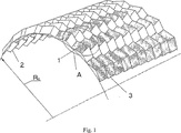
図1ないし図4において、1は突起部のジグザグ線の位置を示し、2は凹部のジグザグ線の位置を示し、3は鋸歯線の位置を示す。 1 to 4, 1 indicates the position of the zigzag line of the protrusion, 2 indicates the position of the zigzag line of the recess, and 3 indicates the position of the sawtooth line.
本発明は以下の態様で実現される。 The present invention is realized in the following modes.
平坦な薄板ブランク(図3)は折曲線1、2、3に沿って折り曲げられ、このブランクは得られた折曲構造体の平坦なブロック(図4)の稜部と結合するために折り曲げられる。折曲構造体展開上の折曲線1、2、3の形状パラメータ:2Sdはジグザグ線とジグザグ線との間の段であり、Ldはこれらのジグザグ線間の距離であり、Vdはジグザグ線の幅である。これらは既製の折曲構造体(図1)のクリンプデザインパラメータ(図2)に関連する。Hはジグザグクリンプの高さであり、Vはジグザグ線の幅であり、2Sはジグザグ線とジグザグ線の間の段であり、2Lは鋸歯線と鋸歯線の間の段であり、それぞれ以下の関係式で表される。

ついで、得られた圧縮ブロックはせん断応力(Ps)を稜部平面(図5)にかけることでブロックを弓状にし、その側方部に
![]()
Next, the compression block obtained was subjected to shear stress (Ps) on the ridge plane (Fig. 5) to make the block arcuate and to the side
![]()
と等しい曲径を与える。ここで、Rcは折曲構造体の曲径であり、tはブランク材料の厚さであり、2S、2L、Hは折曲構造体クリンプデザインパラメータである(上記を参照のこと)。
Gives a radius equal to. Here, Rc is the bending diameter of the folded structure, t is the thickness of the blank material, and 2S, 2L, and H are the folded structure crimp design parameters (see above).
このような条件で固定されてブロックは、折曲構造体材料(たとえば「ノメックス」(NOMEX)に関して再熱温度は180から210℃であり、減衰時間はマイナスである)において、内部応力を緩和するために熱的に処理され、与えられた曲線折曲構造体デザインパラメータに引き伸ばされる。 A fixed block under these conditions relieves internal stresses in the folded structure material (eg, reheat temperature is 180 to 210 ° C. and decay time is negative for “NOMEX”). Is thermally processed and stretched to the given curved structure design parameters.
本願明細書にて請求された曲線折曲構造体のコア部製造方法は中距離用の大型旅客機に適用される航空機の胴体パネルを産業的に製造するために用いられてもよい。本願明細書にて請求された方法を基にした技術により旅客機の胴体部分を挟みこむパネルを産業的に製造するための費用を削減することができる。 The method of manufacturing a core part of a curved bent structure claimed in the present specification may be used for industrially manufacturing an aircraft fuselage panel applied to a large passenger aircraft for a medium distance. With the technology based on the method claimed in the present specification, it is possible to reduce the cost for industrially manufacturing a panel that sandwiches a fuselage portion of a passenger aircraft.
図1ないし図5は本発明の要旨を示すものである。
Claims (2)
折曲線に沿って薄板ブランクを折曲げ、3−Dの内部応力を緩和する構造体を形成するステップと、折曲構造体を得るために前記3−Dの内部応力を緩和する構造体の側方部の結合が完了するまで前記3−Dの内部応力を緩和する構造体を折り畳むステップと、せん断応力をかけることにより、得られた前記折曲構造体を弓状折曲構造体にするステップと、前記弓状折曲構造体の内部応力を緩和するために、前記弓状折曲構造体に熱的処理を施すステップと、前記熱的処理のステップ後に、前記弓状折曲構造体を引き延ばし、全体として曲率半径を持つ前記曲線折曲構造体を製造するステップから成る、曲線折曲構造体を製造するための方法。Bending a thin plate blank along a folding line to form a structure that relaxes the internal stress of 3-D, and a side of the structure that relaxes the internal stress of 3-D to obtain a folded structure Folding the structure that relaxes the internal stress of 3-D until the coupling of the side parts is completed, and applying the shearing stress to make the obtained folded structure into an arcuate folded structure And applying a thermal treatment to the arcuate folded structure to relieve internal stress of the arcuate folded structure, and after the thermal treatment step, A method for manufacturing a curved folded structure comprising the steps of stretching and manufacturing said curved folded structure having an overall radius of curvature.
Applications Claiming Priority (1)
| Application Number | Priority Date | Filing Date | Title |
|---|---|---|---|
| PCT/RU2003/000511 WO2005049307A1 (en) | 2003-11-20 | 2003-11-20 | Method for curvilinear folded structure production |
Publications (2)
| Publication Number | Publication Date |
|---|---|
| JP2007521152A JP2007521152A (en) | 2007-08-02 |
| JP4463764B2 true JP4463764B2 (en) | 2010-05-19 |
Family
ID=34617828
Family Applications (1)
| Application Number | Title | Priority Date | Filing Date |
|---|---|---|---|
| JP2005510786A Expired - Fee Related JP4463764B2 (en) | 2003-11-20 | 2003-11-20 | Method for manufacturing curved bent structure |
Country Status (9)
| Country | Link |
|---|---|
| US (1) | US7410455B2 (en) |
| EP (1) | EP1704044B1 (en) |
| JP (1) | JP4463764B2 (en) |
| CN (1) | CN1878661B (en) |
| AT (1) | ATE502765T1 (en) |
| AU (1) | AU2003303314A1 (en) |
| CA (1) | CA2546568C (en) |
| DE (1) | DE60336515D1 (en) |
| WO (1) | WO2005049307A1 (en) |
Cited By (1)
| Publication number | Priority date | Publication date | Assignee | Title |
|---|---|---|---|---|
| JP2007521153A (en) * | 2003-11-20 | 2007-08-02 | オトゥクリトー アクショナーノ オブシェストヴォ “カザンスキー ナウチノ−イスレドヴァテルスキー インスティトゥート アヴィエイショノイ テクノロギー | Manufacturing method of sandwich panel with zigzag corrugated core |
Families Citing this family (20)
| Publication number | Priority date | Publication date | Assignee | Title |
|---|---|---|---|---|
| US7762938B2 (en) * | 2006-07-24 | 2010-07-27 | Tessellated Group, Llc | Three-dimensional support structure |
| FR2924955B1 (en) * | 2007-12-18 | 2009-12-18 | Arthur Lebee | METHOD AND DEVICE FOR CONFORMING RELIEFS IN A FLAT SHEET |
| US9221230B2 (en) * | 2011-08-22 | 2015-12-29 | The Boeing Company | Honeycomb structure |
| JP6579783B2 (en) * | 2015-04-10 | 2019-09-25 | 株式会社ディスコ | Manufacturing method of bellows |
| US10987891B2 (en) | 2015-07-27 | 2021-04-27 | Karsten Pietsch | Single-layer folding core |
| US10174675B2 (en) | 2015-12-30 | 2019-01-08 | General Electric Company | Acoustic liner for gas turbine engine components |
| US10332501B2 (en) | 2017-02-01 | 2019-06-25 | General Electric Company | Continuous degree of freedom acoustic cores |
| CN108274450A (en) * | 2018-02-09 | 2018-07-13 | 浙江工业大学 | A kind of origami structure based on optical drive bending fold |
| US11059559B2 (en) * | 2018-03-05 | 2021-07-13 | General Electric Company | Acoustic liners with oblique cellular structures |
| US11047304B2 (en) | 2018-08-08 | 2021-06-29 | General Electric Company | Acoustic cores with sound-attenuating protuberances |
| US10823059B2 (en) | 2018-10-03 | 2020-11-03 | General Electric Company | Acoustic core assemblies with mechanically joined acoustic core segments, and methods of mechanically joining acoustic core segments |
| CN109674129B (en) * | 2019-01-22 | 2023-09-01 | 深圳市新技术研究院有限公司 | foldable helmet |
| US11434819B2 (en) * | 2019-03-29 | 2022-09-06 | General Electric Company | Acoustic liners with enhanced acoustic absorption and reduced drag characteristics |
| US11668236B2 (en) | 2020-07-24 | 2023-06-06 | General Electric Company | Acoustic liners with low-frequency sound wave attenuating features |
| USD971019S1 (en) | 2020-07-29 | 2022-11-29 | 3M Innovative Properties Company | Extended sheet |
| USD946907S1 (en) | 2020-07-29 | 2022-03-29 | 3M Innovative Properties Company | Sheet with slits |
| USD1004290S1 (en) | 2020-07-29 | 2023-11-14 | 3M Innovative Properties Company | Sheet with slits |
| USD1016497S1 (en) | 2020-07-29 | 2024-03-05 | 3M Innovative Properties Company | Expanded sheet |
| US11970992B2 (en) | 2021-06-03 | 2024-04-30 | General Electric Company | Acoustic cores and tools and methods for forming the same |
| US11965425B2 (en) | 2022-05-31 | 2024-04-23 | General Electric Company | Airfoil for a turbofan engine |
Family Cites Families (8)
| Publication number | Priority date | Publication date | Assignee | Title |
|---|---|---|---|---|
| US1875188A (en) * | 1932-01-27 | 1932-08-30 | Sherman Products Corp | Unit formed of sheet material |
| US2561147A (en) * | 1947-05-29 | 1951-07-17 | Ai Root Co | Comb foundation |
| NL7714437A (en) * | 1977-12-27 | 1979-06-29 | Leer Koninklijke Emballage | CONSTRUCTION ELEMENT. |
| AU1691083A (en) | 1982-07-07 | 1984-01-12 | Pipamu Pty. Ltd. | Marked sheet for forming 3-d units |
| US5008140A (en) * | 1989-06-01 | 1991-04-16 | Schmertz John C | Biaxially corrugated flexible sheet material |
| US5028474A (en) * | 1989-07-25 | 1991-07-02 | Czaplicki Ronald M | Cellular core structure providing gridlike bearing surfaces on opposing parallel planes of the formed core |
| US5894044A (en) * | 1997-04-21 | 1999-04-13 | The Procter & Gamble Company | Honeycomb structure and method of making |
| US6197402B1 (en) * | 1999-02-01 | 2001-03-06 | Hexcel Corporation | Formable heavy density honeycomb |
-
2003
- 2003-11-20 CA CA2546568A patent/CA2546568C/en not_active Expired - Fee Related
- 2003-11-20 WO PCT/RU2003/000511 patent/WO2005049307A1/en active Application Filing
- 2003-11-20 US US10/579,539 patent/US7410455B2/en not_active Expired - Lifetime
- 2003-11-20 DE DE60336515T patent/DE60336515D1/en not_active Expired - Lifetime
- 2003-11-20 EP EP03819034A patent/EP1704044B1/en not_active Expired - Lifetime
- 2003-11-20 JP JP2005510786A patent/JP4463764B2/en not_active Expired - Fee Related
- 2003-11-20 AT AT03819034T patent/ATE502765T1/en not_active IP Right Cessation
- 2003-11-20 CN CN2003801107114A patent/CN1878661B/en not_active Expired - Fee Related
- 2003-11-20 AU AU2003303314A patent/AU2003303314A1/en not_active Abandoned
Cited By (2)
| Publication number | Priority date | Publication date | Assignee | Title |
|---|---|---|---|---|
| JP2007521153A (en) * | 2003-11-20 | 2007-08-02 | オトゥクリトー アクショナーノ オブシェストヴォ “カザンスキー ナウチノ−イスレドヴァテルスキー インスティトゥート アヴィエイショノイ テクノロギー | Manufacturing method of sandwich panel with zigzag corrugated core |
| JP4740739B2 (en) * | 2003-11-20 | 2011-08-03 | オトゥクリトー アクショナーノ オブシェストヴォ “カザンスキー ナウチノ−イスレドヴァテルスキー インスティトゥート アヴィエイショノイ テクノロギー | Manufacturing method of sandwich panel with zigzag corrugated core |
Also Published As
| Publication number | Publication date |
|---|---|
| US7410455B2 (en) | 2008-08-12 |
| ATE502765T1 (en) | 2011-04-15 |
| EP1704044B1 (en) | 2011-03-23 |
| CN1878661A (en) | 2006-12-13 |
| CA2546568C (en) | 2011-01-04 |
| DE60336515D1 (en) | 2011-05-05 |
| WO2005049307A1 (en) | 2005-06-02 |
| CA2546568A1 (en) | 2005-06-02 |
| AU2003303314A1 (en) | 2005-06-08 |
| US20070080482A1 (en) | 2007-04-12 |
| CN1878661B (en) | 2010-07-28 |
| EP1704044A1 (en) | 2006-09-27 |
| JP2007521152A (en) | 2007-08-02 |
Similar Documents
| Publication | Publication Date | Title |
|---|---|---|
| JP4463764B2 (en) | Method for manufacturing curved bent structure | |
| US9387628B2 (en) | Method and apparatus for fabricating composite stringers | |
| US11370159B2 (en) | Apparatus for forming a contoured hat stiffener | |
| US8465613B2 (en) | Method and apparatus for fabricating variable gauge, contoured composite stiffeners | |
| WO2014042067A1 (en) | Method for producing curved article and skeleton structure member for automobile body shell | |
| KR102340803B1 (en) | Wrinkle reduction in formed composite laminates | |
| CN105682819A (en) | Device for manufacturing component having hat-shaped cross section | |
| CN104392016B (en) | A kind of blank preparation method of rubber pocket shaping thin-walled parts | |
| US20130233474A1 (en) | Method of manufacturing a curved profile made of composite material from a rectilinear preform of fiber plies | |
| US20130327472A1 (en) | Method for producing a curved section piece of composite material from a rectilinear preform of fibre layers | |
| WO2019026732A1 (en) | Press molded article manufacturing method | |
| CN100402180C (en) | Foldable mandrel for production of a single curvature folded core for a sandwich panel | |
| WO2014200675A1 (en) | Method and apparatus for fabricating composite stringers | |
| CN207723263U (en) | Reinforce frame parts rubber pocket shaping dies in a kind of aircraft male bend side | |
| JP4448823B2 (en) | Method for manufacturing sandwich panel cores from composite materials | |
| JP4589870B2 (en) | Thin plate corrugation equipment | |
| US7377521B2 (en) | Process for fabricating a metallic sheet with at least one integrated raised surface zone for a compressed metallic gasket, particularly a cylinder head gasket, and sheet thus obtained | |
| US1343647A (en) | Process for making curved flanged bars | |
| US10457030B2 (en) | Method for manufacturing bamboo framework body | |
| EP1644147B1 (en) | Method for the production of a semi-finished product for a wing-shaped element and a wing-shaped element | |
| JP2019030886A (en) | Manufacturing method of press-molding | |
| CN100402176C (en) | Device for sheet material corrugation | |
| CN109476070B (en) | Thermoplastic shaped parts comprising applied parts and method for the production thereof | |
| RU2259253C1 (en) | Method of manufacture of folded curvilinear structure | |
| RU2254954C1 (en) | Transformed mandrel for making folded filler of laminate single-curvature panel |
Legal Events
| Date | Code | Title | Description |
|---|---|---|---|
| A131 | Notification of reasons for refusal |
Free format text: JAPANESE INTERMEDIATE CODE: A131 Effective date: 20090721 |
|
| A521 | Request for written amendment filed |
Free format text: JAPANESE INTERMEDIATE CODE: A523 Effective date: 20091105 |
|
| TRDD | Decision of grant or rejection written | ||
| A01 | Written decision to grant a patent or to grant a registration (utility model) |
Free format text: JAPANESE INTERMEDIATE CODE: A01 Effective date: 20100209 |
|
| A01 | Written decision to grant a patent or to grant a registration (utility model) |
Free format text: JAPANESE INTERMEDIATE CODE: A01 |
|
| A61 | First payment of annual fees (during grant procedure) |
Free format text: JAPANESE INTERMEDIATE CODE: A61 Effective date: 20100217 |
|
| FPAY | Renewal fee payment (event date is renewal date of database) |
Free format text: PAYMENT UNTIL: 20130226 Year of fee payment: 3 |
|
| R150 | Certificate of patent or registration of utility model |
Ref document number: 4463764 Country of ref document: JP Free format text: JAPANESE INTERMEDIATE CODE: R150 Free format text: JAPANESE INTERMEDIATE CODE: R150 |
|
| FPAY | Renewal fee payment (event date is renewal date of database) |
Free format text: PAYMENT UNTIL: 20140226 Year of fee payment: 4 |
|
| R250 | Receipt of annual fees |
Free format text: JAPANESE INTERMEDIATE CODE: R250 |
|
| R250 | Receipt of annual fees |
Free format text: JAPANESE INTERMEDIATE CODE: R250 |
|
| R250 | Receipt of annual fees |
Free format text: JAPANESE INTERMEDIATE CODE: R250 |
|
| R250 | Receipt of annual fees |
Free format text: JAPANESE INTERMEDIATE CODE: R250 |
|
| R250 | Receipt of annual fees |
Free format text: JAPANESE INTERMEDIATE CODE: R250 |
|
| R250 | Receipt of annual fees |
Free format text: JAPANESE INTERMEDIATE CODE: R250 |
|
| R250 | Receipt of annual fees |
Free format text: JAPANESE INTERMEDIATE CODE: R250 |
|
| R250 | Receipt of annual fees |
Free format text: JAPANESE INTERMEDIATE CODE: R250 |
|
| LAPS | Cancellation because of no payment of annual fees |