JP4740739B2 - Manufacturing method of sandwich panel with zigzag corrugated core - Google Patents
Manufacturing method of sandwich panel with zigzag corrugated core Download PDFInfo
- Publication number
- JP4740739B2 JP4740739B2 JP2005510787A JP2005510787A JP4740739B2 JP 4740739 B2 JP4740739 B2 JP 4740739B2 JP 2005510787 A JP2005510787 A JP 2005510787A JP 2005510787 A JP2005510787 A JP 2005510787A JP 4740739 B2 JP4740739 B2 JP 4740739B2
- Authority
- JP
- Japan
- Prior art keywords
- core
- zigzag
- sandwich panel
- manufacturing
- corrugated core
- Prior art date
- Legal status (The legal status is an assumption and is not a legal conclusion. Google has not performed a legal analysis and makes no representation as to the accuracy of the status listed.)
- Expired - Fee Related
Links
Images


Classifications
-
- B—PERFORMING OPERATIONS; TRANSPORTING
- B32—LAYERED PRODUCTS
- B32B—LAYERED PRODUCTS, i.e. PRODUCTS BUILT-UP OF STRATA OF FLAT OR NON-FLAT, e.g. CELLULAR OR HONEYCOMB, FORM
- B32B3/00—Layered products comprising a layer with external or internal discontinuities or unevennesses, or a layer of non-planar form; Layered products having particular features of form
- B32B3/26—Layered products comprising a layer with external or internal discontinuities or unevennesses, or a layer of non-planar form; Layered products having particular features of form characterised by a particular shape of the outline of the cross-section of a continuous layer; characterised by a layer with cavities or internal voids ; characterised by an apertured layer
- B32B3/28—Layered products comprising a layer with external or internal discontinuities or unevennesses, or a layer of non-planar form; Layered products having particular features of form characterised by a particular shape of the outline of the cross-section of a continuous layer; characterised by a layer with cavities or internal voids ; characterised by an apertured layer characterised by a layer comprising a deformed thin sheet, i.e. the layer having its entire thickness deformed out of the plane, e.g. corrugated, crumpled
-
- B—PERFORMING OPERATIONS; TRANSPORTING
- B21—MECHANICAL METAL-WORKING WITHOUT ESSENTIALLY REMOVING MATERIAL; PUNCHING METAL
- B21D—WORKING OR PROCESSING OF SHEET METAL OR METAL TUBES, RODS OR PROFILES WITHOUT ESSENTIALLY REMOVING MATERIAL; PUNCHING METAL
- B21D47/00—Making rigid structural elements or units, e.g. honeycomb structures
-
- B—PERFORMING OPERATIONS; TRANSPORTING
- B32—LAYERED PRODUCTS
- B32B—LAYERED PRODUCTS, i.e. PRODUCTS BUILT-UP OF STRATA OF FLAT OR NON-FLAT, e.g. CELLULAR OR HONEYCOMB, FORM
- B32B2250/00—Layers arrangement
- B32B2250/40—Symmetrical or sandwich layers, e.g. ABA, ABCBA, ABCCBA
-
- B—PERFORMING OPERATIONS; TRANSPORTING
- B32—LAYERED PRODUCTS
- B32B—LAYERED PRODUCTS, i.e. PRODUCTS BUILT-UP OF STRATA OF FLAT OR NON-FLAT, e.g. CELLULAR OR HONEYCOMB, FORM
- B32B2605/00—Vehicles
- B32B2605/12—Ships
-
- B—PERFORMING OPERATIONS; TRANSPORTING
- B32—LAYERED PRODUCTS
- B32B—LAYERED PRODUCTS, i.e. PRODUCTS BUILT-UP OF STRATA OF FLAT OR NON-FLAT, e.g. CELLULAR OR HONEYCOMB, FORM
- B32B2605/00—Vehicles
- B32B2605/18—Aircraft
-
- Y—GENERAL TAGGING OF NEW TECHNOLOGICAL DEVELOPMENTS; GENERAL TAGGING OF CROSS-SECTIONAL TECHNOLOGIES SPANNING OVER SEVERAL SECTIONS OF THE IPC; TECHNICAL SUBJECTS COVERED BY FORMER USPC CROSS-REFERENCE ART COLLECTIONS [XRACs] AND DIGESTS
- Y10—TECHNICAL SUBJECTS COVERED BY FORMER USPC
- Y10T—TECHNICAL SUBJECTS COVERED BY FORMER US CLASSIFICATION
- Y10T29/00—Metal working
- Y10T29/49—Method of mechanical manufacture
- Y10T29/49616—Structural member making
- Y10T29/49623—Static structure, e.g., a building component
- Y10T29/49625—Openwork, e.g., a truss, joist, frame, lattice-type or box beam
- Y10T29/49627—Frame component
-
- Y—GENERAL TAGGING OF NEW TECHNOLOGICAL DEVELOPMENTS; GENERAL TAGGING OF CROSS-SECTIONAL TECHNOLOGIES SPANNING OVER SEVERAL SECTIONS OF THE IPC; TECHNICAL SUBJECTS COVERED BY FORMER USPC CROSS-REFERENCE ART COLLECTIONS [XRACs] AND DIGESTS
- Y10—TECHNICAL SUBJECTS COVERED BY FORMER USPC
- Y10T—TECHNICAL SUBJECTS COVERED BY FORMER US CLASSIFICATION
- Y10T29/00—Metal working
- Y10T29/49—Method of mechanical manufacture
- Y10T29/49616—Structural member making
- Y10T29/49623—Static structure, e.g., a building component
- Y10T29/49629—Panel
-
- Y—GENERAL TAGGING OF NEW TECHNOLOGICAL DEVELOPMENTS; GENERAL TAGGING OF CROSS-SECTIONAL TECHNOLOGIES SPANNING OVER SEVERAL SECTIONS OF THE IPC; TECHNICAL SUBJECTS COVERED BY FORMER USPC CROSS-REFERENCE ART COLLECTIONS [XRACs] AND DIGESTS
- Y10—TECHNICAL SUBJECTS COVERED BY FORMER USPC
- Y10T—TECHNICAL SUBJECTS COVERED BY FORMER US CLASSIFICATION
- Y10T29/00—Metal working
- Y10T29/49—Method of mechanical manufacture
- Y10T29/49995—Shaping one-piece blank by removing material
-
- Y—GENERAL TAGGING OF NEW TECHNOLOGICAL DEVELOPMENTS; GENERAL TAGGING OF CROSS-SECTIONAL TECHNOLOGIES SPANNING OVER SEVERAL SECTIONS OF THE IPC; TECHNICAL SUBJECTS COVERED BY FORMER USPC CROSS-REFERENCE ART COLLECTIONS [XRACs] AND DIGESTS
- Y10—TECHNICAL SUBJECTS COVERED BY FORMER USPC
- Y10T—TECHNICAL SUBJECTS COVERED BY FORMER US CLASSIFICATION
- Y10T428/00—Stock material or miscellaneous articles
- Y10T428/12—All metal or with adjacent metals
- Y10T428/1234—Honeycomb, or with grain orientation or elongated elements in defined angular relationship in respective components [e.g., parallel, inter- secting, etc.]
Abstract
Description
【技術分野】
本発明は、航空機、造船の建造およびその他の業界において使用されるシート材料からのジグザグの波形コアでのサンドイッチパネルの製造方法としてその最も一般的な形状において定義されることができる。
【背景技術】
コア層および外皮の独立した成形を含み、一方でコアは、印を使って突起および凹部のジグザクのラインに沿って屈曲されるシート素材によって生成されるジグザグの波形コアでのサンドイッチパネルの製造のための方法は、プロトタイプとして考えられる。(旧ソビエト連邦発明者証明書No.1,830,326A1、ジグザグの波形コア製造での曲線のサンドイッチパネルの製造方法、国際特許分類B 23 K 20/00、公報No.28、1993年7月30日)。
本願明細書において示された方法の欠点は、中心点の領域のストレッチ効果による材料の持ち上がりである。折り畳まれた構造の少なくとも4つの隆起線が収束し、2つの平面における同時的な屈曲が生じるその中心点の領域において波形コアを成形する場合、この効果は起こる。それらは、突起および凹部のラインに沿ってというよりも、中心点の領域のみにおいて相互接続するので、コアおよび皮膚との位置接触によりパネル強度を劣化させる結果になる。加えて、成形する場合、素材の材料変形の状態は、相当な効果を適用する必然性によりまったく有利ではないので、まさしくその領域において応力が集中するという結果になり、コア‐外皮の連結強度に悪影響を与える。
【発明の開示】
本発明は、2つの平面における屈曲領域の除去によるコア成形の状態を改良し、かつ、コア‐外皮連結強度を増加させる目的を有する。
本発明によって達成される技術的な結果は、折り畳まれた構造のコア製造品質を有するパネルの改良である。
本願明細書において提示された技術的な結果は、外皮の独立した成形を含むジグザグの波形コアを有するサンドイッチパネルの製造のための周知の方法によって達成され、コアおよびそれらのさらなる連結は、‐技術的な解決法によれば:規定された波形の輪郭が、発生したジグザグ・ライン上の印に沿ったシート素材の屈曲によって得られ、孔を横切る屈曲ライン点におけるジグザグの波形コア発生のシート素材において、dh≧Rbと等しい直径でパンチされる。ここでRbは、最大のシート素材の屈曲半径である。
現状技術の分析によって出願人が保証するものは、本発明のそれらと同一の特徴の組合せによって特徴付けられる類似物が存在しないことを示す。それゆえに、特許請求された技術的な解決法は、特許性における「新規性」を満たす。
特許請求された技術的な解決法の区別と同一の特徴を明らかにする意図を有する提供された領域における周知の解決法のための検索の結果は、その特徴が現状技術の結果から構成されたものではないことを示す。定義された現状技術から、出願人が、明示された技術的な結果の達成の特定された必須の特徴の影響でないことを明らかにすることができた。特許請求された技術は、それゆえに、特許性における「進歩性」を満たす。
【発明を実施するための最良の形態】
特許請求された方法は、以下のようにして実現されることができる。
1)パネルの外皮および内皮1が生成される;
2)屈曲ライン3、4および5が、その平面状態においてコア2の寸法を有するシート素材6上に印をつけられる;屈曲ライン3、4および5のパラメータおよび相対的な位置は、既製のコア2つの設計パラメータ:Ld=f(H,L);Vd=f(V,Ld);Sd=f(V,S,H,L)に関連する。ここにおいて、Hはジグザクの波形の高さであり、Vはジグザクのラインの振幅であり、2Sはジグザク・ライン間のステップであり、2Lはコアの鋸‐歯のライン間のステップであり、2Sdはジグザクのライン間のステップであり、Ldはジグザクのライン間の距離であり、Vdはジグザクのラインの振幅である;
3)孔7は、鋸‐歯5およびジグザクのライン3および4の交差点における素材においてパンチされる;孔7の直径は、dh≧Rbに等しく、ここで、Rbは、既製のコア2の鋸‐歯5およびジグザクのライン3および4の交差点におけるシート素材屈曲半径である;
4)三次元起伏コア構造2が形成されるまで、シート半加工品6は成形される;
5)得られた折り畳み構造2は、外皮および内皮1と例えば付着性を有する複合材料8の使用によって連結される。
【産業上の利用可能性】
ジグザグの波形コアを有するサンドイッチパネルの特許請求された製造方法は、航空機のサンドイッチパネルの工業用の製造において使われることができる。特許請求された方法に基づいて、装置は、ジグザグの波形コア製造品質を改良し、サンドイッチパネル強度の増加を可能にする。
【図面の簡単な説明】
図1−4は、発明の本質を示す。
【図1】は、ジグザクのコア(上皮は示されない)のパネルの全体図である。
【図2】は、波形ジグザグ・ラインの突起および凹部の位置において孔を有するコアの平面素材を示す。
【図3】は、図1の断面図A−Aである。
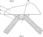
【図4】は、図1の断面図A−A拡大図Iである。
【符号の説明】
図1−4は、以下の位置において存在する。
1 下皮および上皮(図示せず)
2 波形コア
3 波形突起のジグザク・ライン
4 波形凹部のジグザク・ライン
5 鋸−歯のライン
6 コアシート素材
7 ジグザクおよび鋸・歯のラインの位置における孔
8 付着性を有する複合材料【Technical field】
The present invention can be defined in its most common form as a method of manufacturing sandwich panels with zigzag corrugated cores from sheet materials used in aircraft, shipbuilding construction and other industries.
[Background]
Independent molding of the core layer and skin, while the core is used to manufacture sandwich panels with zigzag corrugated cores produced by sheet material bent along the zigzag line of protrusions and recesses using marks A method for this is considered as a prototype. (Former Soviet Inventor's Certificate No. 1,830,326A1, Method for Producing Curve Sandwich Panel in Zigzag Corrugated Core Production, International Patent Classification B 23 K 20/00, Publication No. 28, July 1993 30th).
A disadvantage of the method presented here is the lifting of the material due to the stretch effect in the center point region. This effect occurs when the corrugated core is shaped in the region of its center point where at least four ridges of the folded structure converge and simultaneous bending in two planes occurs. Since they interconnect only in the center point region rather than along the line of protrusions and recesses, the result is a degradation of panel strength due to positional contact with the core and skin. In addition, when forming, the state of material deformation of the material is not at all advantageous due to the necessity of applying a considerable effect, which results in stress concentration in that area, which adversely affects the core-to-skin joint strength. give.
DISCLOSURE OF THE INVENTION
The present invention aims to improve the state of core molding by removing bent areas in two planes and to increase the core-skin connection strength.
The technical result achieved by the present invention is the improvement of a panel having a core manufacturing quality of a folded structure.
The technical results presented herein are achieved by a well-known method for the manufacture of sandwich panels with zigzag corrugated cores, including independent forming of the outer skin, the cores and their further connection being According to a typical solution: the specified corrugated contour is obtained by bending the sheet material along the mark on the generated zigzag line and the sheet material generating the zigzag corrugated core at the bending line point across the hole At a diameter equal to d h ≧ R b . Here, Rb is the bending radius of the maximum sheet material.
What the Applicant guarantees by analysis of the state of the art indicates that there are no analogues characterized by combinations of features identical to those of the present invention. Hence, the claimed technical solution satisfies “novelty” in patentability.
The results of a search for a well-known solution in the provided area with the intent to reveal the same features as the distinction of the claimed technical solution, the features were composed from the results of the state of the art Indicates that it is not a thing. From the state-of-the-art technology defined, it has become possible for the applicant to clarify that it is not the influence of the specified essential features of achieving the stated technical result. The claimed technology therefore satisfies “inventive step” in patentability.
BEST MODE FOR CARRYING OUT THE INVENTION
The claimed method can be implemented as follows.
1) Panel skin and
2) The
3) Hole 7 is punched in the blank at the intersection of saw-
4) The sheet blank 6 is molded until the three-dimensional
5) The resulting folded
[Industrial applicability]
The claimed method of manufacturing sandwich panels with zigzag corrugated cores can be used in the industrial manufacture of aircraft sandwich panels. Based on the claimed method, the device improves zigzag corrugated core manufacturing quality and allows increased sandwich panel strength.
[Brief description of the drawings]
1-4 show the essence of the invention.
FIG. 1 is an overall view of a panel of zig-zag cores (epithelium not shown).
FIG. 2 shows a planar material of a core having holes at the positions of the projections and recesses of the corrugated zigzag line.
FIG. 3 is a cross-sectional view AA of FIG.
4 is a cross-sectional view AA enlarged view I of FIG. 1. FIG.
[Explanation of symbols]
1-4 are present in the following positions.
1 Lower skin and epithelium (not shown)
2 Corrugated core 3 Zigzag line of corrugated protrusion 4 Zigzag line of
Claims (1)
Applications Claiming Priority (1)
| Application Number | Priority Date | Filing Date | Title |
|---|---|---|---|
| PCT/RU2003/000512 WO2005049247A1 (en) | 2003-11-20 | 2003-11-20 | Method for production of sandwich panels with zigzag corrugated core |
Publications (2)
| Publication Number | Publication Date |
|---|---|
| JP2007521153A JP2007521153A (en) | 2007-08-02 |
| JP4740739B2 true JP4740739B2 (en) | 2011-08-03 |
Family
ID=34617829
Family Applications (1)
| Application Number | Title | Priority Date | Filing Date |
|---|---|---|---|
| JP2005510787A Expired - Fee Related JP4740739B2 (en) | 2003-11-20 | 2003-11-20 | Manufacturing method of sandwich panel with zigzag corrugated core |
Country Status (10)
| Country | Link |
|---|---|
| US (1) | US7814658B2 (en) |
| EP (1) | EP1694450B1 (en) |
| JP (1) | JP4740739B2 (en) |
| CN (1) | CN100402179C (en) |
| AT (1) | ATE431206T1 (en) |
| AU (1) | AU2003303315A1 (en) |
| CA (1) | CA2546560C (en) |
| DE (1) | DE60327667D1 (en) |
| RU (1) | RU2259254C1 (en) |
| WO (1) | WO2005049247A1 (en) |
Families Citing this family (33)
| Publication number | Priority date | Publication date | Assignee | Title |
|---|---|---|---|---|
| EP1699577B1 (en) | 2003-12-11 | 2009-05-13 | Otkrytoe Aktsionernoe Obschestvo "Kazansky Nauchno -Isledovatelsky Institut Aviatsionnoi Tekhnologii" | Device for sheet material corrugation |
| RU2588908C2 (en) * | 2005-11-08 | 2016-07-10 | Неапо Ой | System and method of producing cellular plate |
| US8128025B2 (en) * | 2008-03-21 | 2012-03-06 | The Boeing Company | Providing skins for aircraft fuselages |
| US20110281080A1 (en) | 2009-11-20 | 2011-11-17 | E. I. Du Pont De Nemours And Company | Folded Core Based on Carbon Fiber Paper and Articles Made from Same |
| RU2447242C2 (en) * | 2010-07-08 | 2012-04-10 | Хуберт Марие Виллем Ёзеф Каелен | Building panel and method of its producing |
| US20120040131A1 (en) | 2010-08-10 | 2012-02-16 | Speer Dwaine D | Composite Panel Having Perforated Foam Core |
| US20130157001A1 (en) | 2011-12-19 | 2013-06-20 | E I Du Pont De Nemours And Company | Structural core |
| US20130183484A1 (en) | 2012-01-12 | 2013-07-18 | E I Du Pont De Nemours And Company | Core structures comprising tannin resin |
| US9434142B2 (en) | 2012-01-26 | 2016-09-06 | E I Du Pont De Nemours And Company | Method of making a sandwich panel |
| US20140113104A1 (en) | 2012-02-23 | 2014-04-24 | E I Du Pont De Nemours And Company | Fiber-resin composite sheet and article comprising the same |
| US20140349082A1 (en) * | 2013-05-21 | 2014-11-27 | The Boeing Company | Folded Core Panel |
| US9592918B2 (en) | 2014-06-23 | 2017-03-14 | Rohr, Inc. | Acoustic liner |
| DE102014117078B4 (en) | 2014-11-21 | 2022-02-03 | Technische Universität Dresden | Folded core for a sandwich structure, method for producing a folded core and sandwich structure |
| PT3328614T (en) * | 2015-07-27 | 2020-08-31 | Karsten Pietsch | Single-layer folding core |
| US9764818B2 (en) | 2016-02-10 | 2017-09-19 | Rohr, Inc. | Structural, cellular core with corrugated support walls |
| US9761216B2 (en) * | 2016-02-10 | 2017-09-12 | Rohr, Inc. | Acoustic panel with angled corrugated core structures |
| US9704467B1 (en) | 2016-04-15 | 2017-07-11 | Rohr, Inc. | Acoustic panel with corrugated baffles and septums |
| US9978354B2 (en) * | 2016-04-15 | 2018-05-22 | Rohr, Inc. | Acoustic panel with vertical stiffeners |
| CA2986177A1 (en) | 2016-11-21 | 2018-05-21 | Wabash National, L.P. | Composite core with reinforced plastic strips and method thereof |
| FR3060829B1 (en) * | 2016-12-20 | 2019-05-31 | Airbus Operations | STRUCTURE CONSISTING OF ACOUSTIC INSULATION |
| CA3052066A1 (en) | 2017-01-30 | 2018-08-02 | Wabash National, L.P. | Composite core with reinforced areas and method |
| WO2018152180A1 (en) | 2017-02-14 | 2018-08-23 | Wabash National, L.P. | Hybrid composite panel and method |
| US10414481B2 (en) | 2017-02-14 | 2019-09-17 | Rohr, Inc. | Method for forming a structural panel |
| US10436118B2 (en) * | 2017-06-19 | 2019-10-08 | Rohr, Inc. | Acoustic panel with folding chamber |
| US10525636B2 (en) * | 2017-06-19 | 2020-01-07 | Rohr, Inc. | Process for forming a fiber-reinforced composite structure |
| US10695986B2 (en) | 2017-08-22 | 2020-06-30 | Rohr, Inc. | Method for forming a structural panel |
| US11008051B2 (en) | 2018-02-06 | 2021-05-18 | Wabash National, L.P. | Interlocking composite core and method |
| US10906659B2 (en) | 2018-04-03 | 2021-02-02 | Rohr, Inc. | Structured panel with structural reinforcement(s) |
| US11242822B2 (en) | 2018-12-14 | 2022-02-08 | Rohr, Inc. | Structured panel with multi-panel structure(s) |
| US11398214B2 (en) | 2018-12-14 | 2022-07-26 | Rohr, Inc. | Forming a structured panel with one or more structural reinforcements |
| CA3077220A1 (en) | 2019-03-27 | 2020-09-27 | Wabash National, L.P. | Composite panel with connecting strip and method |
| US11572850B2 (en) | 2019-06-04 | 2023-02-07 | Rohr, Inc. | Acoustic panel with one or more structural stiffeners |
| RU2749312C1 (en) * | 2020-10-26 | 2021-06-08 | Федеральное государственное бюджетное образовательное учреждение высшего образования "Московский авиационный институт (национальный исследовательский университет)" | Multilayer supporting surface with discrete filler |
Citations (1)
| Publication number | Priority date | Publication date | Assignee | Title |
|---|---|---|---|---|
| JP4463764B2 (en) * | 2003-11-20 | 2010-05-19 | エアーバス | Method for manufacturing curved bent structure |
Family Cites Families (9)
| Publication number | Priority date | Publication date | Assignee | Title |
|---|---|---|---|---|
| US3341395A (en) * | 1962-12-03 | 1967-09-12 | Solar Reflection Room Corp | Lightweight structural panel |
| JPS644254A (en) * | 1987-06-26 | 1989-01-09 | Toyota Motor Corp | Carrier for exhaust gas cleaning catalyst |
| JPS644254U (en) | 1987-06-29 | 1989-01-11 | ||
| AT389070B (en) * | 1987-08-06 | 1989-10-10 | Guerth Werner Ing | Method and device for producing a welded sandwich panel produced from metal sheets lying one on top of the other |
| AU624388B2 (en) * | 1989-06-27 | 1992-06-11 | High Accolade Limited | Building panel |
| US5635306A (en) | 1992-03-30 | 1997-06-03 | Nippon Steel Corporation | Honeycomb panel and process for producing same |
| JP2001232431A (en) * | 2000-02-23 | 2001-08-28 | Nippon Steel Corp | Truss type haneycomb panel |
| US7429171B2 (en) | 2003-12-11 | 2008-09-30 | Airbus | Device for sheet material corrugation |
| EP1699577B1 (en) | 2003-12-11 | 2009-05-13 | Otkrytoe Aktsionernoe Obschestvo "Kazansky Nauchno -Isledovatelsky Institut Aviatsionnoi Tekhnologii" | Device for sheet material corrugation |
-
2003
- 2003-11-20 WO PCT/RU2003/000512 patent/WO2005049247A1/en active Application Filing
- 2003-11-20 EP EP03819035A patent/EP1694450B1/en not_active Expired - Lifetime
- 2003-11-20 RU RU2004106562/02A patent/RU2259254C1/en not_active IP Right Cessation
- 2003-11-20 AU AU2003303315A patent/AU2003303315A1/en not_active Abandoned
- 2003-11-20 DE DE60327667T patent/DE60327667D1/en not_active Expired - Lifetime
- 2003-11-20 CN CNB2003801107129A patent/CN100402179C/en not_active Expired - Fee Related
- 2003-11-20 JP JP2005510787A patent/JP4740739B2/en not_active Expired - Fee Related
- 2003-11-20 AT AT03819035T patent/ATE431206T1/en not_active IP Right Cessation
- 2003-11-20 CA CA2546560A patent/CA2546560C/en not_active Expired - Fee Related
- 2003-11-20 US US10/579,764 patent/US7814658B2/en not_active Expired - Fee Related
Patent Citations (1)
| Publication number | Priority date | Publication date | Assignee | Title |
|---|---|---|---|---|
| JP4463764B2 (en) * | 2003-11-20 | 2010-05-19 | エアーバス | Method for manufacturing curved bent structure |
Also Published As
| Publication number | Publication date |
|---|---|
| DE60327667D1 (en) | 2009-06-25 |
| WO2005049247A1 (en) | 2005-06-02 |
| US20070141376A1 (en) | 2007-06-21 |
| AU2003303315A1 (en) | 2005-06-08 |
| CA2546560A1 (en) | 2005-06-02 |
| EP1694450B1 (en) | 2009-05-13 |
| US7814658B2 (en) | 2010-10-19 |
| CN100402179C (en) | 2008-07-16 |
| CA2546560C (en) | 2010-03-30 |
| JP2007521153A (en) | 2007-08-02 |
| RU2259254C1 (en) | 2005-08-27 |
| CN1878625A (en) | 2006-12-13 |
| ATE431206T1 (en) | 2009-05-15 |
| EP1694450A1 (en) | 2006-08-30 |
| RU2004106562A (en) | 2005-06-10 |
Similar Documents
| Publication | Publication Date | Title |
|---|---|---|
| JP4740739B2 (en) | Manufacturing method of sandwich panel with zigzag corrugated core | |
| JP4408331B2 (en) | Thermoplastic folding honeycomb structure and manufacturing method thereof | |
| WO1997024221A1 (en) | Fold construction of corrugated fiberboard | |
| JP2007521152A (en) | Method for manufacturing curved bent structure | |
| WO2013076808A1 (en) | Sheet having folding ruled line | |
| US7458802B2 (en) | Foldable mandrel for production of a single curvature folded core for a sandwich panel | |
| KR20060034617A (en) | Metal plate, method for making same and method for folding same | |
| JP4436324B2 (en) | Sandwich panel | |
| TWI226865B (en) | Sheet with folding die-cut lines and the blade for die-cutting the said lines of the said sheet | |
| KR102356422B1 (en) | Manufacturing method of press parts, press forming apparatus, and metal plate for press forming | |
| US5064493A (en) | Method of producing curved honeycomb core material having crimps in one edge | |
| CN210016637U (en) | Mold for manufacturing vibrating diaphragm and vibrating diaphragm | |
| US3226905A (en) | Cellular material | |
| CN213261338U (en) | Creasing line cutter for plastic packing box | |
| JP2003039390A (en) | Corrugated cardboard blanking die, its manufacturing method, and molding of rule assisting member | |
| JP3697170B2 (en) | container | |
| JP2009113291A (en) | Vulcanizing molding die for tire | |
| JPH027907Y2 (en) | ||
| JP2013121716A (en) | Plastic sheet with foldable ruled line, ruled line blade for plastic sheet, and packaging container | |
| RU2415012C1 (en) | Method of producing article from polymer composite material | |
| JPH05329011A (en) | Method for producing decorative chain and decorative chain produced thereby | |
| JP2002104385A (en) | Plastic sheet and built-up container | |
| JP2006231925A (en) | Creased plastic sheet | |
| JPS60237956A (en) | Forming of food having shape of folded-paper crane |
Legal Events
| Date | Code | Title | Description |
|---|---|---|---|
| A977 | Report on retrieval |
Free format text: JAPANESE INTERMEDIATE CODE: A971007 Effective date: 20091102 |
|
| A131 | Notification of reasons for refusal |
Free format text: JAPANESE INTERMEDIATE CODE: A131 Effective date: 20100112 |
|
| A601 | Written request for extension of time |
Free format text: JAPANESE INTERMEDIATE CODE: A601 Effective date: 20100405 |
|
| A602 | Written permission of extension of time |
Free format text: JAPANESE INTERMEDIATE CODE: A602 Effective date: 20100412 |
|
| A521 | Request for written amendment filed |
Free format text: JAPANESE INTERMEDIATE CODE: A523 Effective date: 20100507 |
|
| TRDD | Decision of grant or rejection written | ||
| A01 | Written decision to grant a patent or to grant a registration (utility model) |
Free format text: JAPANESE INTERMEDIATE CODE: A01 Effective date: 20110426 |
|
| A01 | Written decision to grant a patent or to grant a registration (utility model) |
Free format text: JAPANESE INTERMEDIATE CODE: A01 |
|
| A61 | First payment of annual fees (during grant procedure) |
Free format text: JAPANESE INTERMEDIATE CODE: A61 Effective date: 20110502 |
|
| R150 | Certificate of patent or registration of utility model |
Ref document number: 4740739 Country of ref document: JP Free format text: JAPANESE INTERMEDIATE CODE: R150 Free format text: JAPANESE INTERMEDIATE CODE: R150 |
|
| FPAY | Renewal fee payment (event date is renewal date of database) |
Free format text: PAYMENT UNTIL: 20140513 Year of fee payment: 3 |
|
| R250 | Receipt of annual fees |
Free format text: JAPANESE INTERMEDIATE CODE: R250 |
|
| R250 | Receipt of annual fees |
Free format text: JAPANESE INTERMEDIATE CODE: R250 |
|
| R250 | Receipt of annual fees |
Free format text: JAPANESE INTERMEDIATE CODE: R250 |
|
| R250 | Receipt of annual fees |
Free format text: JAPANESE INTERMEDIATE CODE: R250 |
|
| R250 | Receipt of annual fees |
Free format text: JAPANESE INTERMEDIATE CODE: R250 |
|
| R250 | Receipt of annual fees |
Free format text: JAPANESE INTERMEDIATE CODE: R250 |
|
| R250 | Receipt of annual fees |
Free format text: JAPANESE INTERMEDIATE CODE: R250 |
|
| LAPS | Cancellation because of no payment of annual fees |