JP4460744B2 - Digital camera - Google Patents
Digital camera Download PDFInfo
- Publication number
- JP4460744B2 JP4460744B2 JP2000306353A JP2000306353A JP4460744B2 JP 4460744 B2 JP4460744 B2 JP 4460744B2 JP 2000306353 A JP2000306353 A JP 2000306353A JP 2000306353 A JP2000306353 A JP 2000306353A JP 4460744 B2 JP4460744 B2 JP 4460744B2
- Authority
- JP
- Japan
- Prior art keywords
- image
- displayed
- display
- histogram
- button
- Prior art date
- Legal status (The legal status is an assumption and is not a legal conclusion. Google has not performed a legal analysis and makes no representation as to the accuracy of the status listed.)
- Expired - Lifetime
Links
Images


Description
【0001】
【発明の属する技術分野】
本発明は、各種画像情報を対応する画像上に併せてモニタ表示するデジタルカメラに関する。
【0002】
【従来の技術】
近年、パーソナルコンピュータが普及するに連れて、画像データを気軽に撮影して取得することが可能なデジタルカメラも広く一般に普及するようになってきた。
【0003】
この種のデジタルカメラでは、撮像素子として多くの機種で使用されているCCD(Charge Coupled Device:電荷結合素子)の特性から、撮影時には銀塩フィルムを用いるカメラ(以下「銀塩カメラ」と略称する)に比してラチチュード(ダイナミックレンジ)が狭いため、特に露出を正確に制御する必要がある。
【0004】
しかして、デジタルカメラの特性を活かした、適正な露出を得るための一方法として、撮像した画像を構成する画素毎の輝度情報を用いて演算処理を施し、ヒストグラムを得てこれをモニタ表示している液晶ファインダに表示させた上で、適正な露出を得るべく調整を行なうことが考えられている。
なお、画像情報からヒストグラムを作成して表示する技術自体については、例えば特開平7−38801号公報、特開平8−138025号公報、特開平8−189901号公報、特開平8−285526号公報、特開平11−69372号公報、特開平11−88906号公報、特開平11−154235号公報、特開2000−69488号公報、及び特開2000−182045号公報等の多数の公報などにより公知であるものとして、その技術内容についての説明は省略する。
【0005】
【発明が解決しようとする課題】
しかしながら、ヒストグラムは数値を単体で表示するようなものではなく、それ自体で表示に必要な容量が非常に大きなものとなってしまう。
【0006】
したがって、画像そのものと、その時点でのカメラの状態や対応する画像に関する他の情報、例えば記憶媒体であるメモリカードの状態、電源となる電池の消耗状態、露出やホワイトバランスの設定状態、感度情報、ストロボの使用状況、ファイル名とファイルの識別子等を併せてヒストグラムと並列して表示するものとすると、画面上が大変繁雑なものとなってしまい、ヒストグラムのみならず、画像や個々の情報の識別が困難となってしまうという不具合があった。
【0007】
本発明は上記のような実情に鑑みてなされたもので、その目的とするところは、ある程度の表示容量が必要なヒストグラムを使用者の希望に応じて見やすい状態で表示させることが可能なデジタルカメラを提供することにある。
【0008】
【課題を解決するための手段】
請求項1記載の発明は、カメラ本体に備えられ、画像を表示する表示手段と、撮影された複数の画像から上記表示手段に表示する画像を選択する画像選択手段と、上記選択された画像上に、その画像に関連した複数の画像情報を重ねて上記表示手段に表示させる表示処理手段と、上記表示手段に表示された画像に関連した画像情報の1つとして当該画像のヒストグラムを表示させる状態と、ヒストグラムを表示させない状態とを切換変更する表示変更手段と、上記表示変更手段で画像のヒストグラムが表示されている場合に、一方向の操作入力に連動して上記複数の画像をインデックス表示し、上記一方向とは異なる他方向の操作入力に連動して、表示されていた画像のヒストグラムを再び表示する操作入力手段とを備えたことを特徴とする。
【0009】
このような構成とすれば、使用者が必要に応じてヒストグラムを任意に表示させるか否か変更することができる。
【0012】
【発明の実施の形態】
以下本発明の実施の一形態に係る一眼レフ方式のデジタルスチルカメラについて図面を参照して説明する。
【0013】
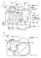
図1、図2はその外観構成を示すもので、図1(1)が上面図、図1(2)が左側面図、図2(1)が背面図、図2(2)が正面図である。
【0014】
これらの図中、カメラ本体1の前面にズームレンズ2が配され、ズームレンズ2の鏡筒周面の前側にフォーカスリング11が、後側にズーム鏡筒リング12が設けられる。
【0015】
また、カメラ本体1の上面前側のズームレンズ2軸上部に内蔵フラッシュ13がここでは伏せた状態で取付けられ、左側面の近傍に設けられた内蔵フラッシュポップアップボタン14の手動操作でポップアップして、点灯可能となる。
【0016】
このカメラ本体1の左側面には、他に「+/−」ボタン15、マクロ撮影を行なうためのマクロボタン16、ここでは図示しない有線リモコンを接続するための有線リモコンジャック17、外部ストロボ搭載時に使用するシンクロソケット(X接点)18、マニュアルフォーカスモード(MF)とオートフォーカスモード(S)とを切換操作するためのフォーカスモード切換レバー19、ここでは図示しないACアダプタを接続するためのジャックを内在したACアダプタキャップ20、ここでは図示しないパーソナルコンピュータやプリンタと接続するための各種端子を内在した端子カバー21、ストラップを取付けるためのストラップ吊環22、後述する液晶モニタの可動角度のロックを解除する液晶モニタロック解除ボタン23、セルフタイマモードなどドライブモードを切換えるドライブボタン24、及び露出の測光パターンを切換えるための測光ボタン25が設けられる。
【0017】
さらに、カメラ本体1の上面には、上記内蔵フラッシュ13の後ろ側に設けられた外部ストロボ搭載のためのホットシュー26の他に、モノクロ液晶パネルによるカメラの動作状態等を表示するガイドパネル27、撮像した画像を記憶するメモリカードとしてスマートメディア(登録商標)/コンパクトフラッシュ(登録商標)を切換え選択するためのSM/CFボタン28、後述する液晶モニタのバックライトの点灯/消灯を操作するバックライトボタン29、撮影条件の各種モードを回転操作により設定するモード選択ダイヤル30、このモード選択ダイヤル30下部に同軸的に配置した電源レバー31、ストラップを取付けるためのストラップ吊環32、ホワイトバランスのモードセットを行なうWBモードセットボタン33、後述するメインダイヤルの操作と組合わせて各種撮影条件の設定を行なうサブダイヤル34、シャッターレリーズのためのレリーズボタン35、撮影する画質モードを設定するための画質モード設定ボタン36、及び上記内蔵フラッシュ13の発光パターン及び光量を切替え設定するためのフラッシュ切替えボタン37が設けられる。
【0018】
加えてカメラ本体1の背面には、光学ファインダ38、上記液晶モニタロック解除ボタン23を操作することで可動できる液晶モニタ39、セルフタイマ撮影時に使用するアイピースシャッタレバー40、上記サブダイヤル34の操作とも組合わせて各種撮影条件の設定を行なうメインダイヤル41、上記液晶モニタ39のオン/オフを設定する液晶モニタON/OFFボタン42、メニュー項目を液晶モニタ39に表示させるためのメニューボタン43、液晶モニタ39で表示された項目を選択するための十字ボタン44、選択された項目を選定するためのOKボタン45、後述するカード蓋の不用意な開閉を制限するためのカード蓋ロックレバー46、自動露出状態を一時的にロックするためのAELボタン47、記録媒体であるメモリカードの収納部を被覆するカード蓋48、メモリカードの装着状態をインジケータ表示するカードLED49、ヒストグラムの表示/非表示を設定するINFOボタン50、撮影した画像をプロテクト状態に設定するプロテクトボタン51、及び液晶モニタ39で表示している画像を1コマ単位で消去するための1コマ消去ボタン52が設けられる。
【0019】
上記光学ファインダ38は、その胴周面部に視度調整リング53を設けることで、眼鏡使用者にも正確なピント合わせ等ができるようにしている。
【0020】
しかしてカメラ本体1の前面には、上記ズームレンズ2の他に、ストラップ吊環22にここでは図示しないワイヤレスリモートコントローラからの赤外線信号を受信する一方、セルフタイマ使用時に点滅するリモコン受光窓/セルフLED54と、白い紙などを被写体とした状態で1回の操作によりホワイトバランスをとらせるためのWB(ワンプッシュオート)入力ボタン55とが設けられる。
【0021】
次いで、図3により上記カメラ本体1内の電子回路の構成について説明する。
【0022】
同図で、撮影モード時に撮像レンズ61を介して入射された被写体の光像は撮像素子62の撮像面上に結像する。
【0023】
この撮像素子62は、例えば原色系(RGB)のカラーフィルタを有するCCDで構成され、後述するシステムコントローラ63に駆動制御されるもので、光電変換によって得た画像データはデジタルプロセス回路64に出力される。
【0024】
デジタルプロセス回路64は、撮像素子62から得た画像データをフレームメモリ65に展開記憶させる。このフレームメモリ65は、システムコントローラ63からの制御に基づいてメモリコントローラ77が各種動作を制御するもので、フレームメモリ65に記憶された画像データに対してホワイトバランス調整、階調変換、色変換(原色系画像データから輝度色差系画像データへの変換)、シャープネス調整、等の画像処理を施した後にリサイズした主画像とサムネイル画像の各画像データを生成する。
【0025】
このうち、主画像の画像データは、フレームメモリ65から圧縮伸長回路66へ読出され、この圧縮伸長回路66にて予めこのデジタルカメラで選択設定されているデータ圧縮方式に従って圧縮され、それからシステムコントローラ63からの信号にしたがって出力を切換選択するセレクタ67を介して第1のカードインターフェース68または第2のカードインターフェース69へ送出される。
【0026】
また、サムネイル画像の画像データは、上記液晶モニタ39でモニタ表示される他、フレームメモリ65から圧縮伸長回路66へ読出され、所定の圧縮率をもってJPEG(Joint Photograph coding Experts Group)方式で圧縮され、それからやはりセレクタ67を介して第1のカードインターフェース68または第2のカードインターフェース69へ送出される。
【0027】
ここで、上記主画像の画像データを特にJPEG方式で圧縮するべく選択設定がなされている場合に限っては、主画像とサムネイルの両画像データが1つにまとめられ、1つの画像データファイルとして第1のカードインターフェース68または第2のカードインターフェース69へ送出される。
【0028】
しかして、第1のカードインターフェース68は、セレクタ67を介して受けた画像データを第1のスロット70に装着されている第1のメモリカード71のファイルフォーマットに従って適宜変換した上で該第1のメモリカード71に書込む。
【0029】
なお、この第1のスロット70における第1のメモリカード71の装着の有無は第1のスロット70に設けられた、例えばマイクロスイッチで構成されるスロット装着検出手段72により検出され、その検出信号は上記システムコントローラ63へ送られる。
【0030】
同様にして、第2のカードインターフェース69は、セレクタ67を介して受けた画像データを第2のスロット73に装着されている第2のメモリカード74のファイルフォーマットに従って適宜変換した上で該第2のメモリカード74に書込む。
【0031】
なお、この第2のスロット73における第2のメモリカード74の装着の有無は第2のスロット73に設けられた、例えばマイクロスイッチで構成されるスロット装着検出手段75により検出され、その検出信号は上記システムコントローラ63へ送られる。
【0032】
第1のメモリカード71及び第2のメモリカード74は、それぞれ異なる規格に従ったフラッシュメモリを封入したものであり、ここでは上記カード蓋48内の収納部に収納されるものとして、上述した如く第1のメモリカード21をスマートメディア、第2のメモリカード24をコンパクトフラッシュであるものとする。
【0033】
システムコントローラ63は、EEPROM78に固定記憶されている動作プログラムにしたがってこのデジタルカメラ全体の動作制御を行なうもので、上記図1及び図2で示した各種のボタン及びダイヤルの操作に応じた信号を直接入力する。
【0034】
またシステムコントローラ63は、その時点での日付と時刻とを計時するカレンダ回路79及び上記光学ファインダ38内で動作状況を表示するためのファインダ内LCD80とも接続され、これらの動作を制御する。
【0035】
次に上記実施の形態の動作について説明する。
【0036】
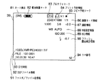
図4は再生モード時にヒストグラムを表示していない状態で、液晶モニタ39に選択した画像と共に表示される画像情報の内容を例示する。
【0037】
図中、画面左上端にカード表示81と電池残量マーク82とが表示されており、「SM」はその時点で表示している画像が第1のメモリカード71であるスマートメディアから読出されたものであることを示す。電池残量マーク82はこの状態では満充電状態であることを示している。
【0038】
画面の右上端側では、プロテクトマーク83、プリント予約マーク84、コピー予約マーク85、画質モード情報86、撮影情報87、WB設定情報88、ISO情報89、及びフラッシュ露出補正情報90を表示している。
【0039】
上記プロテクトマーク83は、その画像にプロテクトがかけられている場合に表示する。
【0040】
プリント予約マーク84は、プリンタを模したプリント予約マークと「×予約枚数(例えば「1」)」とでプリントの予約を行なっている枚数を表示する。
【0041】
コピー予約マーク85は、その画像のコピーが予約されていることを示す。
【0042】
画質モード情報86は、その画像が例えば(横)2240画素×(縦)1680画素で圧縮率が「1/1」であることを示す。
【0043】
WB設定情報88は、ここではホワイトバランス(WB)が自動(AUTO)に設定されていることを示すが、マニュアル設定された場合にはその色温度を光源のシンボルマークと共に表示し、また上記WB(ワンプッシュ)入力ボタン55が操作されていた場合にはその内容を専用のシンボルマークで示す。
【0044】
ISO情報89は、撮影時の撮像素子62の感度設定を例えば「ISO 200」のように表示する。
【0045】
フラッシュ露出補正情報90は、ここではその画像が内蔵フラッシュ13を発光させて撮影されたものであり、且つ「0.7(EV)」分だけ減光されていたことを示す。
【0046】
加えて画面の左下端側では、フォルダ/ファイル名情報91、DCFファイル情報92、及び日付時刻93を表示している。
【0047】
フォルダ/ファイル名情報91は、例えばDCF(Design rule for File system)規格に則った数字3文字+5文字のフォルダ名と、4文字+4桁の数字にそのファイルの識別子を付加して示す。
【0048】
DCFファイル情報92は、上記DCF規格に基づいて自動的に付加されたファイル情報である。
【0049】
日付時刻93は、その画像の撮影時の日付と時刻とを示す。
【0050】
また、画面の右下端部では、選択しているメモリカード中でのその画像のシリアル番号を示すコマ番号94を表示している。
【0051】
続いて図5により主として上記システムコントローラ63がボタン、ダイヤルの操作入力に対応して制御する、特に再生モード時の画像情報の遷移状態について説明する。
【0052】
ここでは、1コマ再生モード中のヒストグラム非表示モードで表示する画像情報の量を複数階層、例えば3階層に設定するものとする。
【0053】
電源レバー31の操作による電源投入後、モード選択ダイヤル30で再生モードが選択されるか、あるいは撮影モードから液晶モニタON/OFFボタン42が2回連続して操作されると再生モードとなり、その時点でヒストグラムを表示するモードがすでにカスタムメニューで選択されているか否かを判断する。
【0054】
ここで、ヒストグラム非表示モードとなっている場合、図中に図5(a)〜図5(c)で示す如く、上記図4で示した多数の画素表示を階層的に表示している。
【0055】
すなわち、図5(a)で示す第1階層では、選択した画像に対してその画像情報としてカード表示81、電池残量マーク82、及びコマ番号94のみを表示し、図5(b)に示す第2階層ではこれらに加えてプリント予約マーク84、コピー予約マーク85、及び日付時刻93を表示している。
【0056】
そして、図5(c)に示す第3階層では、さらに上記に加えて、撮影情報87、WB設定情報88、ISO情報89、フラッシュ露出補正情報90、フォルダ/ファイル名情報91、及びDCFファイル情報92を表示することで、上記図4に示した如くすべての画像情報を表示することになる。
【0057】
これら階層の変更は図示する如くメインダイヤル41またはサブダイヤル34を正逆回動操作することにより手軽に行なうことができるものとなる。
【0058】
一方、再生モード時でヒストグラム表示モードが予め設定されている場合には、まず図5(d)で示す如く、上記図5(a)で示したヒストグラム非表示モードの第1階層と同様に、、選択した画像に対してその画像情報としてカード表示81、電池残量マーク82、及びコマ番号94を表示するとともに、その画像のヒストグラム95を表示する。
【0059】
すなわち、この図5(d)に示すヒストグラム表示モードでヒストグラム95を表示している状態は、上記図5(a)で示したヒストグラム非表示モードの最も画像情報の量が少ない第1階層と比して、ヒストグラム95が表示されている点のみ相違するもので、上述したカスタムメニューでの変更設定に限らず、図示するように液晶モニタ39下部の上記INFOボタン50を操作する毎に、ヒストグラム95の表示状態と非表示状態とを容易に切換設定できるものとする。
【0060】
しかるに、上記図5(d)に示したヒストグラム95の表示状態からメインダイヤル41またはサブダイヤル34を「CW」方向(手指を遠ざける方向)へ操作すると、図5(e)に示すようにその時点で選択しているメモリカードに記録されている複数の画像によりインデックス表示状態となるものとする。
【0061】
このとき、カード表示81に加えて各画像如くコマ番号94が表示され、また選択している画像のみが他の画像と区別するように所定の色付けの枠で表示されるもので、十字ボタン44を任意に操作することにより、選択している画像を上下左右に移動させ、あるいは表示されている画像範囲をスクロールさせることができる。
【0062】
しかして、任意の画像を選択している状態でメインダイヤル41またはサブダイヤル34を「CCW」方向(手指を近付ける方向)へ操作すると、その選択した画像に基づいて再び上記図5(d)に示したヒストグラム95を表示する状態に移行するものとする。
【0063】
また、上記図5(d)に示したヒストグラム95の表示状態からメインダイヤル41またはサブダイヤル34を「CCW」方向(手指を近付ける方向)へ操作すると、図5(f)に示すようにヒストグラム95を表示したまま、その時点で選択している画像をその中心位置を基準として順次拡大表示するものとする。
【0064】
このとき、画面の上下左右各各辺の中央では図示する如く外側に向いた3角形を表示することにより、画像を拡大表示していることを表わすものとする。
【0065】
また、このような拡大表示状態からメインダイヤル41またはサブダイヤル34を「CW」方向(手指を遠ざける方向)へ操作すると、上記とは反対に、次第にヒストグラム95を表示したまま、その時点で選択している画像をその中心位置を基準として拡大率を縮小して表示するものとする。
【0066】
しかして、画像が元の大きさとなった時点でメインダイヤル41またはサブダイヤル34による「CW」方向(手指を遠ざける方向)への操作を無効とし、上記図5(d)に示した表示状態に戻る。
【0067】
このように、再生モード時にあっては使用者が必要に応じてヒストグラム95を例えばINFOボタン50のような簡単な操作により任意に表示させることができるものとしたため、気軽にヒストグラム95の内容を確認することができる一方、液晶モニタ39の画面で占有する面積が大きいヒストグラム95が不要であれば、即座にヒストグラム95を表示しないように切換えることもできる。
【0068】
なお、上記実施の形態では3階層中の最も画像情報の量が少ない階層でINFOボタン50を操作することにより、ヒストグラムを画像上に合わせて表示させるものとしたが、さらにもう1階層、まったく画像情報を表示しない階層を設定し、その階層での表示状態から特定の操作を行なうことによりヒストグラムを表示させるものとしても良い。
【0069】
このように、特に他の画像情報の数が最も少ないか、またはまったくない階層の表示中にヒストグラムの表示を行なうか否かを切換変更することを可能としたため、ヒストグラムが他の画像情報の中で見づらいものとなってしまうことがなく、より明確にその内容を把握することができる。
【0070】
その他、本発明は上記実施の形態に限らず、その要旨を逸脱しない範囲内で種々変形して実施することが可能であるものとする。
【0071】
さらに、上記実施の形態には種々の段階の発明が含まれており、開示される複数の構成要件における適宜な組合わせにより種々の発明が抽出され得る。例えば、実施の形態に示される全構成要件からいくつかの構成要件が削除されても、発明が解決しようとする課題の欄で述べた課題の少なくとも1つが解決でき、発明の効果の欄で述べられている効果の少なくとも1つが得られる場合には、この構成要件が削除された構成が発明として抽出され得る。
【0072】
【発明の効果】
本発明によれば、使用者が必要に応じてヒストグラムを任意に表示させるか否か変更することができる。
【図面の簡単な説明】
【図1】本発明の実施の一形態に係るデジタルスチルカメラの外観構成を示す上面図と側面図。
【図2】同実施の形態に係るデジタルスチルカメラの外観構成を示す背面図と正面図。
【図3】同実施の形態に係る電子回路の構成を示すブロック図。
【図4】同実施の形態に係る液晶モニタでの表示内容を例示する図。
【図5】同実施の形態に係る液晶モニタ画面での画像情報の表示遷移状態を示す図。
【符号の説明】
1…カメラ本体
2…ズームレンズ
13…内蔵フラッシュ
15…「+/−」ボタン
23…液晶モニタロック解除ボタン
27…ガイドパネル
28…SM/CFボタン
29…バックライトボタン
30…モード選択ダイヤル
31…電源レバー
33…WBモードセットボタン
34…サブダイヤル
35…レリーズボタン
36…画質モード設定ボタン
37…フラッシュ切替えボタン
38…光学ファインダ
39…液晶モニタ
41…メインダイヤル
42…液晶モニタON/OFFボタン
43…メニューボタン
44…十字ボタン
45…OKボタン
49…カードLED
50…INFOボタン
51…プロテクトボタン
52…1コマ消去ボタン
55…WB(ワンプッシュオート)入力ボタン
61…撮像レンズ
62…撮像素子
63…システムコントローラ
64…デジタルプロセス回路
65…フレームメモリ
66…圧縮伸長回路
67…セレクタ
68…第1のカードインターフェース
69…第2のカードインターフェース
70…第1のスロット
71…第1のメモリカード
72…スロット装着検出手段
73…第2のスロット
74…第2のメモリカード
75…スロット装着検出手段
77…メモリコントローラ
78…EEPROM
79…カレンダ回路
80…ファインダ内LCD
81…カード表示
82…電池残量マーク
83…プロテクトマーク
84…プリント予約マーク
85…コピー予約マーク
86…画質モード情報
87…撮影情報
88…WB設定情報
89…ISO情報
90…フラッシュ露出補正情報
91…フォルダ/ファイル名情報
92…DCFファイル情報
93…日付時刻
94…コマ番号
95…ヒストグラム[0001]
BACKGROUND OF THE INVENTION
The present invention relates to a digital camera that displays various image information on a corresponding image on a monitor.
[0002]
[Prior art]
In recent years, with the widespread use of personal computers, digital cameras that can easily shoot and acquire image data have become widespread.
[0003]
In this type of digital camera, due to the characteristics of CCD (Charge Coupled Device) used in many models as an image pickup device, a camera using a silver salt film at the time of photographing (hereinafter abbreviated as “silver salt camera”). ), The latitude (dynamic range) is narrower, so it is necessary to control the exposure accurately.
[0004]
Therefore, as a method for obtaining appropriate exposure by taking advantage of the characteristics of the digital camera, arithmetic processing is performed using luminance information for each pixel constituting the captured image, and a histogram is obtained and displayed on a monitor. It is considered to make an adjustment to obtain an appropriate exposure after being displayed on a liquid crystal finder.
As for the technology itself for creating and displaying a histogram from image information, for example , Japanese Patent Laid-Open No. 7-38801, Japanese Patent Laid-Open No. 8-13825, Japanese Patent Laid-Open No. 8-189901, Japanese Patent Laid-Open No. 8-285526, Known from numerous publications such as JP-A-11-69372, JP-A-11-88906, JP-A-11-154235, JP-A-2000-69488, and JP-A-2000-182045. As a matter of course, description of the technical contents is omitted.
[0005]
[Problems to be solved by the invention]
However, the histogram is not such that a numerical value is displayed alone, and the capacity required for display itself becomes very large.
[0006]
Therefore, the image itself, the current camera status and other information related to the image, such as the status of the memory card that is the storage medium, the power consumption of the battery that is the power source, the exposure and white balance settings, and sensitivity information If the strobe usage status, file name and file identifier, etc. are displayed in parallel with the histogram, the screen will become very complicated, and not only the histogram but also images and individual information will be displayed. There was a problem that it would be difficult to identify.
[0007]
The present invention has been made in view of the above circumstances, and an object of the present invention is to provide a digital camera capable of displaying a histogram that requires a certain amount of display capacity in an easy-to-view state according to the desire of the user. Is to provide.
[0008]
[Means for Solving the Problems]
The invention described in
[0009]
With such a configuration, the user can change whether or not to arbitrarily display the histogram as necessary.
[0012]
DETAILED DESCRIPTION OF THE INVENTION
A single-lens reflex digital still camera according to an embodiment of the present invention will be described below with reference to the drawings.
[0013]
FIG. 1 and FIG. 2 show the external configuration, FIG. 1 (1) is a top view, FIG. 1 (2) is a left side view, FIG. 2 (1) is a rear view, and FIG. 2 (2) is a front view. It is.
[0014]
In these drawings, a
[0015]
In addition, the built-in
[0016]
On the left side of the
[0017]
Further, on the upper surface of the
[0018]
In addition, an
[0019]
The
[0020]
Thus, on the front surface of the
[0021]
Next, the configuration of the electronic circuit in the
[0022]
In the drawing, the light image of the subject incident through the imaging lens 61 in the imaging mode is formed on the imaging surface of the
[0023]
The
[0024]
The
[0025]
Among these, the image data of the main image is read from the
[0026]
Further, the image data of the thumbnail image is displayed on the
[0027]
Here, only when the image data of the main image is selected and set to be compressed particularly by the JPEG method, both the main image and thumbnail image data are combined into one image data file. The data is sent to the
[0028]
Thus, the
[0029]
Whether or not the
[0030]
Similarly, the
[0031]
Whether or not the
[0032]
The
[0033]
The
[0034]
The
[0035]
Next, the operation of the above embodiment will be described.
[0036]
FIG. 4 illustrates the contents of the image information displayed together with the selected image on the liquid crystal monitor 39 in a state where the histogram is not displayed in the reproduction mode.
[0037]
In the figure, a
[0038]
On the upper right side of the screen, a
[0039]
The protect
[0040]
The print reservation mark 84 displays the number of print reservations made with a print reservation mark imitating a printer and “× reserved number (for example,“ 1 ”)”.
[0041]
The copy reservation mark 85 indicates that the copy of the image is reserved.
[0042]
The image
[0043]
The
[0044]
The
[0045]
Here, the flash
[0046]
In addition, on the lower left side of the screen, folder /
[0047]
The folder /
[0048]
The
[0049]
The
[0050]
In the lower right corner of the screen, a
[0051]
Next, a transition state of image information in the playback mode, which is controlled mainly by the
[0052]
Here, it is assumed that the amount of image information displayed in the histogram non-display mode in the single frame playback mode is set to a plurality of layers, for example, three layers.
[0053]
After the power is turned on by operating the power lever 31, the playback mode is entered when the playback mode is selected with the mode selection dial 30 or when the LCD monitor ON /
[0054]
Here, when the histogram non-display mode is set, as shown in FIGS. 5A to 5C, the pixel display shown in FIG. 4 is hierarchically displayed.
[0055]
That is, in the first hierarchy shown in FIG. 5A, only the
[0056]
In the third hierarchy shown in FIG. 5C, in addition to the above, shooting information 87,
[0057]
These levels can be easily changed by rotating the
[0058]
On the other hand, when the histogram display mode is set in advance in the playback mode, first, as shown in FIG. 5D, as in the first layer of the histogram non-display mode shown in FIG. The
[0059]
That is, the state in which the
[0060]
However, when the
[0061]
At this time, in addition to the
[0062]
Thus, when the
[0063]
Further, when the
[0064]
At this time, it is assumed that the image is displayed in an enlarged manner by displaying a triangle facing outward as shown in the center of each side of the top, bottom, left, and right sides of the screen.
[0065]
Further, when the
[0066]
Thus, when the image becomes the original size, the operation in the “CW” direction (direction in which the finger is moved away) by the
[0067]
As described above, in the playback mode, the user can arbitrarily display the
[0068]
In the above embodiment, the histogram is displayed on the image by operating the
[0069]
As described above, since it is possible to change whether or not to display the histogram during the display of the hierarchy in which the number of other image information is the smallest or none at all, the histogram is included in the other image information. This makes it possible to grasp the contents more clearly.
[0070]
In addition, the present invention is not limited to the above-described embodiment, and various modifications can be made without departing from the scope of the invention.
[0071]
Further, the above embodiments include inventions at various stages, and various inventions can be extracted by appropriately combining a plurality of disclosed constituent elements. For example, even if some constituent elements are deleted from all the constituent elements shown in the embodiment, at least one of the problems described in the column of the problem to be solved by the invention can be solved, and described in the column of the effect of the invention. In a case where at least one of the obtained effects can be obtained, a configuration in which this configuration requirement is deleted can be extracted as an invention.
[0072]
【The invention's effect】
According to the present invention , the user can change whether or not to arbitrarily display the histogram as necessary.
[Brief description of the drawings]
FIGS. 1A and 1B are a top view and a side view showing an external configuration of a digital still camera according to an embodiment of the present invention. FIGS.
FIGS. 2A and 2B are a rear view and a front view showing an external configuration of the digital still camera according to the embodiment; FIGS.
FIG. 3 is a block diagram showing a configuration of an electronic circuit according to the embodiment.
FIG. 4 is a view illustrating display contents on the liquid crystal monitor according to the embodiment;
FIG. 5 is a view showing a display transition state of image information on the liquid crystal monitor screen according to the embodiment;
[Explanation of symbols]
DESCRIPTION OF
50 ...
79 ...
81 ... Card display 82 ...
Claims (4)
撮影された複数の画像から上記表示手段に表示する画像を選択する画像選択手段と、
上記選択された画像上に、その画像に関連した複数の画像情報を重ねて上記表示手段に表示させる表示処理手段と、
上記表示手段に表示された画像に関連した画像情報の1つとして当該画像のヒストグラムを表示させる状態と、ヒストグラムを表示させない状態とを切換変更する表示変更手段と、
上記表示変更手段で画像のヒストグラムが表示されている場合に、一方向の操作入力に連動して上記複数の画像をインデックス表示し、上記一方向とは異なる他方向の操作入力に連動して、表示されていた画像のヒストグラムを再び表示する操作入力手段と
を備えたことを特徴とするデジタルカメラ。A display means provided in the camera body for displaying an image;
Image selection means for selecting an image to be displayed on the display means from a plurality of captured images;
Display processing means for causing the display means to display a plurality of pieces of image information related to the image on the selected image;
Display changing means for switching between a state in which a histogram of the image is displayed as one of the image information related to the image displayed on the display means and a state in which the histogram is not displayed;
When the histogram of the image is displayed by the display changing means, the plurality of images are displayed in an index in conjunction with an operation input in one direction, and in conjunction with an operation input in another direction different from the one direction, A digital camera comprising operation input means for again displaying a histogram of a displayed image.
上記表示変更手段は、上記複数階層中で表示する画像情報の数が最も少ない階層の表示中に、ヒストグラムを表示させる状態と表示させない状態とで切換変更する
ことを特徴とする請求項1記載のデジタルカメラ。Variable setting means for variably setting the number of image information to be displayed in a stepwise manner by setting any one of a plurality of layers to a plurality of image information related to the image displayed on the display unit. Prepared,
2. The display change unit according to claim 1, wherein the display change means switches and switches between a state in which a histogram is displayed and a state in which the histogram is not displayed during display of a layer having the smallest number of image information to be displayed in the plurality of layers. Digital camera.
Priority Applications (1)
| Application Number | Priority Date | Filing Date | Title |
|---|---|---|---|
| JP2000306353A JP4460744B2 (en) | 2000-10-05 | 2000-10-05 | Digital camera |
Applications Claiming Priority (1)
| Application Number | Priority Date | Filing Date | Title |
|---|---|---|---|
| JP2000306353A JP4460744B2 (en) | 2000-10-05 | 2000-10-05 | Digital camera |
Publications (3)
| Publication Number | Publication Date |
|---|---|
| JP2002118772A JP2002118772A (en) | 2002-04-19 |
| JP2002118772A5 JP2002118772A5 (en) | 2007-11-29 |
| JP4460744B2 true JP4460744B2 (en) | 2010-05-12 |
Family
ID=18787059
Family Applications (1)
| Application Number | Title | Priority Date | Filing Date |
|---|---|---|---|
| JP2000306353A Expired - Lifetime JP4460744B2 (en) | 2000-10-05 | 2000-10-05 | Digital camera |
Country Status (1)
| Country | Link |
|---|---|
| JP (1) | JP4460744B2 (en) |
Families Citing this family (3)
| Publication number | Priority date | Publication date | Assignee | Title |
|---|---|---|---|---|
| JP2005295497A (en) * | 2004-03-10 | 2005-10-20 | Seiko Epson Corp | Image quality display device, digital camera, developing apparatus, image quality display method and image quality display program |
| JP4689490B2 (en) * | 2006-02-16 | 2011-05-25 | キヤノン株式会社 | Digital camera and control method thereof |
| JP4928340B2 (en) * | 2007-04-26 | 2012-05-09 | キヤノン株式会社 | Imaging apparatus and display control method |
-
2000
- 2000-10-05 JP JP2000306353A patent/JP4460744B2/en not_active Expired - Lifetime
Also Published As
| Publication number | Publication date |
|---|---|
| JP2002118772A (en) | 2002-04-19 |
Similar Documents
| Publication | Publication Date | Title |
|---|---|---|
| JP4140181B2 (en) | Electronic camera | |
| JP3978530B2 (en) | Electronic camera | |
| JP4158304B2 (en) | Image reproduction method and apparatus, and electronic camera | |
| US5950031A (en) | Combined film and digital camera having display | |
| USRE44997E1 (en) | Photographing apparatus | |
| JP4196394B2 (en) | Input device and electronic camera | |
| JP4144144B2 (en) | Image recording method and apparatus | |
| EP1453055A1 (en) | Digital camera with bracketing mode | |
| JP4460744B2 (en) | Digital camera | |
| JP4509829B2 (en) | Camera device | |
| JP4534176B2 (en) | Electronic camera | |
| JP4445657B2 (en) | Digital photography device | |
| JP4783073B2 (en) | Camera, display control apparatus for the camera, and display control method therefor | |
| JP4238448B2 (en) | Electronic camera | |
| JP4277119B2 (en) | Electronic camera | |
| CN100454979C (en) | Digital camera having plurality of image recording media and control method for the same | |
| JP3997970B2 (en) | Camera device | |
| JP2005136655A (en) | Camera | |
| JP2002354315A (en) | Digital camera | |
| JP2004064299A (en) | Digital camera | |
| JP5481984B2 (en) | Imaging device | |
| JP2005117119A (en) | Digital camera | |
| JP2002330325A (en) | Digital camera | |
| JP2001157158A (en) | Electronic camera | |
| JP5476851B2 (en) | Imaging device |
Legal Events
| Date | Code | Title | Description |
|---|---|---|---|
| A621 | Written request for application examination |
Free format text: JAPANESE INTERMEDIATE CODE: A621 Effective date: 20071003 |
|
| A521 | Request for written amendment filed |
Free format text: JAPANESE INTERMEDIATE CODE: A523 Effective date: 20071012 |
|
| A131 | Notification of reasons for refusal |
Free format text: JAPANESE INTERMEDIATE CODE: A131 Effective date: 20090818 |
|
| A521 | Request for written amendment filed |
Free format text: JAPANESE INTERMEDIATE CODE: A523 Effective date: 20091008 |
|
| A131 | Notification of reasons for refusal |
Free format text: JAPANESE INTERMEDIATE CODE: A131 Effective date: 20091104 |
|
| A521 | Request for written amendment filed |
Free format text: JAPANESE INTERMEDIATE CODE: A523 Effective date: 20091218 |
|
| TRDD | Decision of grant or rejection written | ||
| A01 | Written decision to grant a patent or to grant a registration (utility model) |
Free format text: JAPANESE INTERMEDIATE CODE: A01 Effective date: 20100119 |
|
| A01 | Written decision to grant a patent or to grant a registration (utility model) |
Free format text: JAPANESE INTERMEDIATE CODE: A01 |
|
| A61 | First payment of annual fees (during grant procedure) |
Free format text: JAPANESE INTERMEDIATE CODE: A61 Effective date: 20100215 |
|
| R151 | Written notification of patent or utility model registration |
Ref document number: 4460744 Country of ref document: JP Free format text: JAPANESE INTERMEDIATE CODE: R151 |
|
| FPAY | Renewal fee payment (event date is renewal date of database) |
Free format text: PAYMENT UNTIL: 20130219 Year of fee payment: 3 |
|
| FPAY | Renewal fee payment (event date is renewal date of database) |
Free format text: PAYMENT UNTIL: 20140219 Year of fee payment: 4 |
|
| S531 | Written request for registration of change of domicile |
Free format text: JAPANESE INTERMEDIATE CODE: R313531 |
|
| R350 | Written notification of registration of transfer |
Free format text: JAPANESE INTERMEDIATE CODE: R350 |
|
| R250 | Receipt of annual fees |
Free format text: JAPANESE INTERMEDIATE CODE: R250 |
|
| R250 | Receipt of annual fees |
Free format text: JAPANESE INTERMEDIATE CODE: R250 |