JP4460708B2 - Permanent magnet motor control device that combines engine starter and generator - Google Patents
Permanent magnet motor control device that combines engine starter and generator Download PDFInfo
- Publication number
- JP4460708B2 JP4460708B2 JP2000091090A JP2000091090A JP4460708B2 JP 4460708 B2 JP4460708 B2 JP 4460708B2 JP 2000091090 A JP2000091090 A JP 2000091090A JP 2000091090 A JP2000091090 A JP 2000091090A JP 4460708 B2 JP4460708 B2 JP 4460708B2
- Authority
- JP
- Japan
- Prior art keywords
- permanent magnet
- magnet motor
- battery
- chopper
- voltage
- Prior art date
- Legal status (The legal status is an assumption and is not a legal conclusion. Google has not performed a legal analysis and makes no representation as to the accuracy of the status listed.)
- Expired - Fee Related
Links
Images


Classifications
-
- B—PERFORMING OPERATIONS; TRANSPORTING
- B60—VEHICLES IN GENERAL
- B60W—CONJOINT CONTROL OF VEHICLE SUB-UNITS OF DIFFERENT TYPE OR DIFFERENT FUNCTION; CONTROL SYSTEMS SPECIALLY ADAPTED FOR HYBRID VEHICLES; ROAD VEHICLE DRIVE CONTROL SYSTEMS FOR PURPOSES NOT RELATED TO THE CONTROL OF A PARTICULAR SUB-UNIT
- B60W10/00—Conjoint control of vehicle sub-units of different type or different function
- B60W10/04—Conjoint control of vehicle sub-units of different type or different function including control of propulsion units
- B60W10/08—Conjoint control of vehicle sub-units of different type or different function including control of propulsion units including control of electric propulsion units, e.g. motors or generators
-
- B—PERFORMING OPERATIONS; TRANSPORTING
- B60—VEHICLES IN GENERAL
- B60K—ARRANGEMENT OR MOUNTING OF PROPULSION UNITS OR OF TRANSMISSIONS IN VEHICLES; ARRANGEMENT OR MOUNTING OF PLURAL DIVERSE PRIME-MOVERS IN VEHICLES; AUXILIARY DRIVES FOR VEHICLES; INSTRUMENTATION OR DASHBOARDS FOR VEHICLES; ARRANGEMENTS IN CONNECTION WITH COOLING, AIR INTAKE, GAS EXHAUST OR FUEL SUPPLY OF PROPULSION UNITS IN VEHICLES
- B60K6/00—Arrangement or mounting of plural diverse prime-movers for mutual or common propulsion, e.g. hybrid propulsion systems comprising electric motors and internal combustion engines ; Control systems therefor, i.e. systems controlling two or more prime movers, or controlling one of these prime movers and any of the transmission, drive or drive units Informative references: mechanical gearings with secondary electric drive F16H3/72; arrangements for handling mechanical energy structurally associated with the dynamo-electric machine H02K7/00; machines comprising structurally interrelated motor and generator parts H02K51/00; dynamo-electric machines not otherwise provided for in H02K see H02K99/00
- B60K6/20—Arrangement or mounting of plural diverse prime-movers for mutual or common propulsion, e.g. hybrid propulsion systems comprising electric motors and internal combustion engines ; Control systems therefor, i.e. systems controlling two or more prime movers, or controlling one of these prime movers and any of the transmission, drive or drive units Informative references: mechanical gearings with secondary electric drive F16H3/72; arrangements for handling mechanical energy structurally associated with the dynamo-electric machine H02K7/00; machines comprising structurally interrelated motor and generator parts H02K51/00; dynamo-electric machines not otherwise provided for in H02K see H02K99/00 the prime-movers consisting of electric motors and internal combustion engines, e.g. HEVs
- B60K6/42—Arrangement or mounting of plural diverse prime-movers for mutual or common propulsion, e.g. hybrid propulsion systems comprising electric motors and internal combustion engines ; Control systems therefor, i.e. systems controlling two or more prime movers, or controlling one of these prime movers and any of the transmission, drive or drive units Informative references: mechanical gearings with secondary electric drive F16H3/72; arrangements for handling mechanical energy structurally associated with the dynamo-electric machine H02K7/00; machines comprising structurally interrelated motor and generator parts H02K51/00; dynamo-electric machines not otherwise provided for in H02K see H02K99/00 the prime-movers consisting of electric motors and internal combustion engines, e.g. HEVs characterised by the architecture of the hybrid electric vehicle
- B60K6/48—Parallel type
- B60K6/485—Motor-assist type
-
- F—MECHANICAL ENGINEERING; LIGHTING; HEATING; WEAPONS; BLASTING
- F02—COMBUSTION ENGINES; HOT-GAS OR COMBUSTION-PRODUCT ENGINE PLANTS
- F02N—STARTING OF COMBUSTION ENGINES; STARTING AIDS FOR SUCH ENGINES, NOT OTHERWISE PROVIDED FOR
- F02N11/00—Starting of engines by means of electric motors
- F02N11/04—Starting of engines by means of electric motors the motors being associated with current generators
-
- H—ELECTRICITY
- H02—GENERATION; CONVERSION OR DISTRIBUTION OF ELECTRIC POWER
- H02P—CONTROL OR REGULATION OF ELECTRIC MOTORS, ELECTRIC GENERATORS OR DYNAMO-ELECTRIC CONVERTERS; CONTROLLING TRANSFORMERS, REACTORS OR CHOKE COILS
- H02P9/00—Arrangements for controlling electric generators for the purpose of obtaining a desired output
- H02P9/08—Control of generator circuit during starting or stopping of driving means, e.g. for initiating excitation
-
- B—PERFORMING OPERATIONS; TRANSPORTING
- B60—VEHICLES IN GENERAL
- B60K—ARRANGEMENT OR MOUNTING OF PROPULSION UNITS OR OF TRANSMISSIONS IN VEHICLES; ARRANGEMENT OR MOUNTING OF PLURAL DIVERSE PRIME-MOVERS IN VEHICLES; AUXILIARY DRIVES FOR VEHICLES; INSTRUMENTATION OR DASHBOARDS FOR VEHICLES; ARRANGEMENTS IN CONNECTION WITH COOLING, AIR INTAKE, GAS EXHAUST OR FUEL SUPPLY OF PROPULSION UNITS IN VEHICLES
- B60K6/00—Arrangement or mounting of plural diverse prime-movers for mutual or common propulsion, e.g. hybrid propulsion systems comprising electric motors and internal combustion engines ; Control systems therefor, i.e. systems controlling two or more prime movers, or controlling one of these prime movers and any of the transmission, drive or drive units Informative references: mechanical gearings with secondary electric drive F16H3/72; arrangements for handling mechanical energy structurally associated with the dynamo-electric machine H02K7/00; machines comprising structurally interrelated motor and generator parts H02K51/00; dynamo-electric machines not otherwise provided for in H02K see H02K99/00
- B60K6/20—Arrangement or mounting of plural diverse prime-movers for mutual or common propulsion, e.g. hybrid propulsion systems comprising electric motors and internal combustion engines ; Control systems therefor, i.e. systems controlling two or more prime movers, or controlling one of these prime movers and any of the transmission, drive or drive units Informative references: mechanical gearings with secondary electric drive F16H3/72; arrangements for handling mechanical energy structurally associated with the dynamo-electric machine H02K7/00; machines comprising structurally interrelated motor and generator parts H02K51/00; dynamo-electric machines not otherwise provided for in H02K see H02K99/00 the prime-movers consisting of electric motors and internal combustion engines, e.g. HEVs
- B60K6/22—Arrangement or mounting of plural diverse prime-movers for mutual or common propulsion, e.g. hybrid propulsion systems comprising electric motors and internal combustion engines ; Control systems therefor, i.e. systems controlling two or more prime movers, or controlling one of these prime movers and any of the transmission, drive or drive units Informative references: mechanical gearings with secondary electric drive F16H3/72; arrangements for handling mechanical energy structurally associated with the dynamo-electric machine H02K7/00; machines comprising structurally interrelated motor and generator parts H02K51/00; dynamo-electric machines not otherwise provided for in H02K see H02K99/00 the prime-movers consisting of electric motors and internal combustion engines, e.g. HEVs characterised by apparatus, components or means specially adapted for HEVs
- B60K6/26—Arrangement or mounting of plural diverse prime-movers for mutual or common propulsion, e.g. hybrid propulsion systems comprising electric motors and internal combustion engines ; Control systems therefor, i.e. systems controlling two or more prime movers, or controlling one of these prime movers and any of the transmission, drive or drive units Informative references: mechanical gearings with secondary electric drive F16H3/72; arrangements for handling mechanical energy structurally associated with the dynamo-electric machine H02K7/00; machines comprising structurally interrelated motor and generator parts H02K51/00; dynamo-electric machines not otherwise provided for in H02K see H02K99/00 the prime-movers consisting of electric motors and internal combustion engines, e.g. HEVs characterised by apparatus, components or means specially adapted for HEVs characterised by the motors or the generators
- B60K2006/268—Electric drive motor starts the engine, i.e. used as starter motor
-
- Y—GENERAL TAGGING OF NEW TECHNOLOGICAL DEVELOPMENTS; GENERAL TAGGING OF CROSS-SECTIONAL TECHNOLOGIES SPANNING OVER SEVERAL SECTIONS OF THE IPC; TECHNICAL SUBJECTS COVERED BY FORMER USPC CROSS-REFERENCE ART COLLECTIONS [XRACs] AND DIGESTS
- Y02—TECHNOLOGIES OR APPLICATIONS FOR MITIGATION OR ADAPTATION AGAINST CLIMATE CHANGE
- Y02T—CLIMATE CHANGE MITIGATION TECHNOLOGIES RELATED TO TRANSPORTATION
- Y02T10/00—Road transport of goods or passengers
- Y02T10/60—Other road transportation technologies with climate change mitigation effect
- Y02T10/62—Hybrid vehicles
Landscapes
- Engineering & Computer Science (AREA)
- Chemical & Material Sciences (AREA)
- Combustion & Propulsion (AREA)
- Mechanical Engineering (AREA)
- Transportation (AREA)
- Power Engineering (AREA)
- General Engineering & Computer Science (AREA)
- Control Of Motors That Do Not Use Commutators (AREA)
- Control Of Charge By Means Of Generators (AREA)
- Electric Propulsion And Braking For Vehicles (AREA)
- Dc-Dc Converters (AREA)
Description
【0001】
【発明の属する技術分野】
本発明は、エンジンのスタータおよびバッテリの充電用の発電機として兼用する永久磁石モータの制御装置に関する。
【0002】
【従来の技術】
従来より、車両例えば自動車においては、エンジンの出力軸にクラッチを介してスタータ(セルモータ)が連繋されていて、このスタータはリレースイッチを介してバッテリに接続されており、また、エンジンの出力軸に発電機が連繋されていて、この発電機はバッテリに接続されている。そして、イグニッションキーがスタータ位置に回されてスタータリレーが動作されると、そのリレースイッチがオンしてバッテリからスタータに電源が供給され、スタータが動作してエンジンの出力軸を駆動し、エンジンをを始動させる。その後、クラッチが切り離されるとともに、スタータリレーが復帰されてリレースイッチがオフされるようになっている。エンジンが始動すると、発電機が駆動されて発電し、これによりバッテリが充電されるようになっている。
【0003】
【発明が解決しようとする課題】
従来の構成では、エンジンのスタータおよびバッテリ充電用の発電機の2つを必要とするため、自動車の搭載スペースが大きくなる不具合がある。また、エンジンの始動時には、スタータには大トルクを発生すべく大電流が流れるので、スタータリレーとしては、この大電流に耐え得る大形のものを用いる必要がある。更に、エンジンの始動後は、このエンジンによりスタータが逆駆動されないようにクラッチが設けられているが、クラッチを設けることは搭載スペーサが一層大きくなる不具合がある。
【0004】
本発明は上述の事情に鑑みてなされたものであり、その目的は、車両の搭載スペースが小さくて済み、大形のスタータリレーを必要としないエンジンのスタータと発電機とを兼用した永久磁石モータの制御装置を提供することにある。
【0005】
【課題を解決するための手段】
請求項1記載のエンジンのスタータと発電機とを兼用した永久磁石モータの制御装置は、車両に搭載されたバッテリと、エンジンの出力軸に連繋された永久磁石モータと、フライホイールダイオードを有する複数のスイッチング素子を直列に接続してなるアームを1つ以上有し、入力端子がコンデンサに接続され、出力端子が前記永久磁石モータに接続されて、直流を交流に変換して前記永久磁石モータに供給するための駆動回路と、前記バッテリ側に位置して前記コンデンサに並列に設けられ、ダイオードを並列に有する2個のスイッチング素子を直列接続してなるチョッパ回路と、このチョッパ回路の中性点と前記バッテリとの間に接続されたリアクトルと、前記駆動回路および前記チョッパ回路のスイッチング素子をオンオフ制御する制御手段とを具備する構成に特徴を有する。
【0006】
更に、前記制御手段を、永久磁石モータをエンジンのスタータとして動作させる場合には、チョッパ回路を非動作若しくは昇圧チョッパとして動作させることにより駆動回路を介して前記永久磁石モータを駆動させ、前記永久磁石モータを発電機として動作させる場合には、その永久磁石モータの発電電圧がバッテリの電圧より高いときは、前記駆動回路を非動作にして、前記チョッパ回路を降圧チョッパとして動作させることにより前記バッテリを充電させ、前記永久磁石モータの発電電圧が前記バッテリの電圧より低いときは、前記チョッパ回路を非動作にして、前記駆動回路の負側スイッチング素子をオンオフしてその駆動回路を昇圧チョッパをして動作させることにより前記バッテリを充電させるように構成するところに特徴を有する。
【0007】
以上のような構成によれば、永久磁石モータをエンジンの出力軸に連繋して、この永久磁石モータを、エンジンの始動時にはエンジンを駆動するスタータとして動作させ、エンジンの始動後はエンジンにより駆動されてバッテリを充電するための発電機として動作させるようにしたので、1つの永久磁石モータにスタータと発電機とを兼用させることができ、従って、スタータと発電機の2つを搭載するようにした従来に比し、車両の搭載スペースを小さくすることができ、しかも、エンジンの出力軸と永久磁石モータとの間には従来のようなクラッチを設ける必要がないので、搭載スペースを一層小さくすることができる。そして、永久磁石モータをスタータとして動作させる場合には、永久磁石モータを制御手段によって制御される駆動回路により駆動するようにしたので、バッテリと永久磁石モータとの間に、従来のようなスタータリレーのリレースイッチを接続する必要がなく、従って、大形なスタータリレーを設ける必要もない。
【0008】
そして、永久磁石モータをスタータとして動作させる場合において、バッテリの端子間電圧が定格電圧であるときには、チョッパ回路を非動作状態にしてバッテリの端子間電圧によりコンデンサを充電させ、バッテリの端子間電圧が定格電圧より低いときには、リアクトルとともにチョッパ回路を昇圧チョッパとして動作させることによりバッテリの端子間電圧を昇圧してコンデンサを充電させるようにし、逆に、永久磁石モータを発電機として動作させる場合において、永久磁石モータの発電電圧がバッテリの定格電圧より高いときには、駆動回路を非動作状態にし、チョッパ回路を降圧チョッパとして動作させてバッテリを充電させ、永久磁石モータの発電電圧がバッテリの定格電圧より低いときには、チョッパ回路を非動作状態(但し、正側のトランジスタはオン)にし、駆動回路を永久磁石モータのステータコイルとともに昇圧チョッパとして動作させてバッテリを充電させるようにしたので、スタータとして動作すべく大トルクを有する永久磁石モータであっても、バッテリを充電させるための発電機として動作させることができるものであり、逆に、バッテリの電圧が低下しても昇圧により大トルクの永久磁石モータを始動させることができる。
【0009】
請求項2記載のエンジンのスタータと発電機とを兼用した永久磁石モータの制御装置は、チョッパ回路に、ダイオードを並列に有する2個のスイッチング素子を直列接続してなるもう1つのチョッパ回路を並列に接続し、そのチョッパ回路の中性点とバッテリとの間にリアクトルを接続するようにした構成に特徴を有する。
【0010】
請求項3記載のエンジンのスタータと発電機とを兼用した永久磁石モータの制御装置は、制御手段を、2つのチョッパ回路において、昇圧時には負側のスイッチング素子を180度のタイミング位相差をもってオンオフさせ、降圧時には正側のスイッチング素子を180度のタイミング位相差をもってオンオフさせるように構成するところに特徴を有する。
【0011】
以上のような構成によれば、2つのチョッパ回路において、昇圧時には負側のスイッチング素子が180度のタイミング位相差をもってオンオフされるので、コンデンサにリップルの少ない直流電源電圧を供給することができる。また、降圧時には正側のスイッチング素子が180度のタイミング位相差をもってオンオフされるので、リップルの少ない電圧でバッテリを充電することができる。
【0012】
請求項4記載のエンジンのスタータと発電機とを兼用した永久磁石モータの制御装置は、2つのリアクトルを、1つのコアに2つのコイルを巻装して構成するところに特徴を有する。
このような構成によれば、リアクトルを小形化できる。
【0013】
【発明の実施の形態】
以下、本発明を自動車に適用した第1の実施例につき、図1および図2を参照しながら説明する。
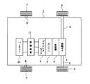
先ず、全体構成を示す図2において、車両たる自動車1には、エンジン2が搭載されている。このエンジン2は、変速機3および差動ギヤ4を介して後側ホイール5,5の車軸6,6を駆動するようになっている。尚、自動車1の前側ホイール7,7の車軸8,8は非駆動である。また、自動車1には、永久磁石モータとしてブラシレスモータ9が搭載されている。このブラシレスモータ9は、図1に示すように、複数相例えば3相のステータコイル9U,9Vおよび9Wを有するステータと、永久磁石形のロータとを備えている。そして、このブラシレスモータ9のロータのシャフトは、エンジン2の出力軸に連繋例えば直結されている。更に、自動車1には、鉛蓄電池等の充電可能な36ボルト定格(ハイブリットカー仕様)のバッテリ10が搭載されており、このバッテリ10とブラシレスモータ9との間で後述する制御装置11を介して電力の授受が行なわれるようになっている。
【0014】
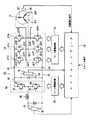
さて、制御装置11の具体的構成につき、図1に従って述べる。駆動回路としてのインバータ回路12は、6個のスイッチング素子たるNPN形のトランジスタ13U,13V,13Wおよび14U,14V,14Wを3相ブリッジ接続して構成されたもので、夫々のコレクタ,エミッタ間には、フライホイールダイオード15U,15V,15Wおよび16U,16V,16Wが接続され、以て、3つのアーム17U,17Vおよび17Wを有する。そして、このインバータ回路12の入力端子18,19は直流母線20,21に接続され、出力端子22U,22V,22Wはブラシレスモータ9のステータコイル9U,9Vおよび9Wの各一端子に接続されている。尚、ステータコイル9U,9Vおよび9Wの各他端子は共通に接続されている。また、直流母線21はバッテリ10の負端子に接続されているとともに、直流母線20,21間にはコンデンサ23が接続されている。
【0015】
チョッパ回路24は、例えば2つのスイッチング素子(3つ以上の複数でも可)としてのNPN形のトランジスタ25,26およびダイオード27,28を有するもので、そのトランジスタ25において、コレクタは直流母線20に接続され、エミッタはトランジスタ26のコレクタに接続され、そのトランジスタ26のエミッタは直流母線21に接続され、トランジスタ25,26の夫々のコレクタ,エミッタ間にはダイオード27,28が接続されている。そして、チョッパ回路24の中性点は、リアクトル29を介してバッテリ10の正端子に接続されている。この場合、上記リアクトル29は、コアにコイルを巻装して構成されている。
【0016】
バッテリ電圧検出器30は、バッテリ10に並列に接続されていて、バッテリ10の端子間電圧を検出するようになっている。主回路電圧検出器31は、コンデンサ23に並列に接続されていて、コンデンサ23の端子間電圧(主回路電圧)を検出するようになっている。そして、位置検出器32は、ブラシレスモータ9に配設されていて、ブラシレスモータ9のロータの位置を検出するホールICから構成されている。
【0017】
さて、制御手段たるマイクロコンピュータ33は、各入力ポートにバッテリ電圧検出器30,主回路電圧検出器31および位置検出器32の各出力端子が接続され、各出力ポートがフォトカプラ式のベースドライブ回路34,35の各入力端子に接続されていて、後述する如くに動作する。そして、ベースドライブ回路34の各出力端子は、インバータ回路12のトランジスタ13Uないし13Wおよび14Uないし14Wのベースに夫々接続され、ベースドライブ回路35の各出力端子は、チョッパ回路24のトランジスタ25,26のベースに夫々接続されている。
【0018】
次に、本実施例の作用につき説明する。
〈ブラシレスモータ9をスタータとして動作させる場合〉
マイクロコンピュータ33は、バッテリ電圧検出器30が検出するバッテリ10の端子間電圧が定格電圧であるときには、チョッパ回路24を非動作状態とする。これにより、バッテリ10の直流電圧はリアクトル29およびダイオード27を介してコンデンサ23に印加され、コンデンサ23はインバータ回路12の入力電圧に適した電圧に充電される。また、マイクロコンピュータ33は、バッテリ電圧検出器30が検出するバッテリ10の端子間電圧が定格電圧より低いときには、ベースドライブ回路35にPWM信号を与えることによりチョッパ回路24の負側のトランジスタ26にベース信号を与えるようになり、トランジスタ26はPWM信号のデューティに応じてオンオフされる。
【0019】
チョッパ回路24において、トランジスタ26がオンされると、リアクトル29およびランジスタ26の経路でバッテリ10からリアクトル29に電流が流れ、次に、トランジスタ26がオフされると、リアクトル29に蓄積されたエネルギーがダイオード27を介して放出され、以て、昇圧された電圧がコンデンサ23に印加される。この場合、電圧の昇圧率は、PWM信号のデューティで決定されるものであり、PWM信号のデューティが大になるほど昇圧率も大になる。マイクロコンピュータ33は、バッテリ10の端子間電圧に応じてPWM信号のデューティを決定するようになっており、これによりコンデンサ23はインバータ回路12の入力電圧に適した電圧に充電される。このように、チョッパ回路24とリアクトル29とは、このときには昇圧チョッパとして動作するのである。
【0020】
マイクロコンピュータ33にスタータ信号が与えられると、マイクロコンピュータ33は、位置検出器32からの位置検出信号に基づいて通電タイミング信号を生成してベース駆動回路34に与え、ベース駆動回路34はこれに応じてインバータ回路12のトランジスタ13Uないし13Wおよび14Uないし14Wのベースに順次ベース信号を与えるようになり、トランジスタ13Uないし13Wおよび14Uないし14Wが順次オンオフされる。これにより、ブラシレスモータ9のステータコイル9Uないし9Wに例えば120度通電方式により交流電流が流れ、ロータが回転を始める。ブラシレスモータ9が始動すると、そのシャフトに連結されたエンジン2の出力軸が回転駆動され、エンジン2が始動するようになる。即ち、このときには、ブラシレスモータ9は、エンジン2のスタータとして機能するのである。
【0021】
〈ブラシレスモータ9を発電機として動作させる場合〉
マイクロコンピュータ33は、エンジンが始動したときには、インバータ回路12のトランジスタ13Uないし13Wおよび14Uないし14Wのベースに対するベース信号の供給を停止してこれらを全てオフさせ、以て、インバータ回路12を非動作状態にする。エンジン2が始動されると、今度は、ブラシレスモータ9のシャフト即ちロータがエンジン2の出力軸によって回転駆動されて、ステータコイル9Uないし9Wに電圧が誘起され、この誘起された交流電圧は、インバータ回路12のフライホイールダイオード15Uないし15Wおよび16Uないし16Wが全波整流回路として機能することにより直流電圧に変換されてコンデンサ23に印加される。即ち、このときには、ブラシレスモータ9は、発電機として機能するのである。
【0022】
ところで、エンジン2の出力軸の回転速度は、アクセルの踏込み度合に応じて高低変化するものである。従って、エンジン2の出力軸の回転速度に応じてブラシレスモータ9のステータコイル9Uないし9Wに誘起される電圧(発電電圧)も高低変化するものであり、コンデンサ23に印加される直流電圧も高低変化する。
【0023】
マイクロコンピュータ33は、主回路電圧検出器31が検出するコンデンサ23の端子間電圧(主回路電圧)がバッテリ10の定格電圧より高いときには(ブラシレスモータ9の発電電圧が高いときには)、ベースドライブ回路35にPWM信号を与えることによりチョッパ回路24の正側のトランジスタ25のベースにベース信号を与えるようになり、トランジスタ25はPWM信号のデューティに応じてオンオフされる。
【0024】
チョッパ回路24において、トランジスタ25がオンされると、コンデンサ23の端子間電圧は、トランジスタ25のオン期間だけリアクトル29を介してバッテリ10に印加されるので、結果として、バッテリ10にはコンデンサ23の端子間電圧が降圧されて印加されるようになる。この場合、電圧の降圧率は、PWM信号のデューティで決定されるものであり、PWM信号のデューティが小になるほど降圧率が大になる。マイクロコンピュータ33は、コンデンサ23の端子間電圧に応じてPWM信号のデューティを決定するようになっており、これによりバッテリ10は適正な電圧で充電される。このように、チョッパ回路24とリアクトル29とは、このときには降圧チョッパとして動作するのである。
【0025】
また、マイクロコンピュータ33は、主回路電圧検出器31が検出するコンデンサ23の端子間電圧(主回路電圧)がバッテリ10の定格電圧より低いときには(ブラシレスモータ9の発電電圧が低いときには)、チョッパ回路24を非動作状態とする。ここで、チョッパ回路24を非動作状態にするとは、トランジスタ25,26にオンオフの繰返し動作を行わせないということで、ここでは、トランジスタ25はオン状態にされる。
【0026】
更に、マイクロコンピュータ33は、ベースドライブ回路34にPWM信号を与えることによりインバータ回路12の負側のトランジスタ14Uないし14Wのベースにベース信号を与えるようになり、トランジスタ14Uないし14WはPWM信号のデューティに応じてオンオフされる。この場合、インバータ回路12においては、ブラシレスモータ9のステータコイル9Uから電流が流出するパターンのときには、トランジスタ14Uがオンオフされ、ステータコイル9Vから電流が流出するパターンのときには、トランジスタ14Vがオンオフされ、ステータコイル9Wから電流が流出するパターンのときには、トランジスタ14Wがオンオフされる。
【0027】
インバータ回路12において、例えばトランジスタ14Uがオンされると、ステータコイル9Uとステータコイル9V若しくは9Wとに誘起される電圧によって、ステータコイル9Uとトランジスタ14Uとフリーホイールダイオード16V若しくは16Wとステータコイル9V若しくは9Wとの経路で循環電流が流れて、ステータコイル9Uとステータコイル9V若しくは9Wとにエネルギーが蓄積され、次に、トランジスタ14Uがオフされると、ステータコイル9Uとステータコイル9V若しくは9Wとに蓄積されたエネルギーがフリーホイールダイオード15Uを介して放出され、以て、昇圧された電圧がコンデンサ23に印加される。この場合、電圧の昇圧率は、PWM信号のデューティで決定されるものであり、PWM信号のデューティが大になるほど昇圧率も大になる。マイクロコンピュータ33は、バッテリ10の端子間電圧に応じてPWM信号のデューティを決定するようになっており、これによりコンデンサ23はバッテリ10の充電にに適した電圧に充電される。
【0028】
インバータ回路12のトランジスタ14Vおよび14Wがオンオフされることによる昇圧の原理は、上述したトランジスタ14Uのオンオフのときと同様であり、従って、このときには、インバータ回路12は、ステータコイル9Uないし9Wをリアクトルとする昇圧チョッパとして機能するのである。
【0029】
このように本実施例によれば、ブラシレスモータ9のシャフトをエンジン2の出力軸に直結して、このブラシレスモータ9を、エンジン2の始動時にはエンジン2を駆動するスタータとして動作させ、エンジン2の始動後はエンジン2により駆動されてバッテリ10を充電するための発電機として動作させるようにしたので、1つのブラシレスモータ9にエンジン2のスタータとバッテリ10の充電用の発電機とを兼用させることができ、従って、スタータと発電機の2つを搭載するようにした従来に比し、自動車1の搭載スペースを小さくすることができ、しかも、エンジン2の出力軸とブラシレスモータ9のシャフトとの間には従来のようなクラッチを設ける必要がないので、自動車1の搭載スペースを一層小さくすることができる。そして、ブラシレスモータ9をスタータとして動作させる場合には、ブラシレスモータ9をマイクロコンピュータ33によって制御されるインバータ回路12により駆動するようにしたので、バッテリ10とブラシレスモータ9との間に、従来のようなスタータリレーのリレースイッチを接続する必要がなく、従って、大形なスタータリレーを設ける必要もない。
【0030】
ここで、ブラシレスモータ9をスタータとして動作させる場合において、バッテリ10の端子間電圧が定格電圧であるときには、チョッパ回路24を非動作状態にしてバッテリ10の端子間電圧によりコンデンサ23を充電させ、バッテリ10の端子間電圧が定格電圧より低いときには、リアクトル29とともにチョッパ回路24を昇圧チョッパとして動作させることによりバッテリ10の端子間電圧を昇圧してコンデンサ23を充電させるようにした。逆に、ブラシレスモータ9を発電機として動作させる場合において、ブラシレスモータ9の発電電圧がバッテリ10の定格電圧より高いときには、インバータ回路12を非動作状態にし、チョッパ回路24を降圧チョッパとして動作させてバッテリ10を充電させ、ブラシレスモータ9の発電電圧がバッテリ10の定格電圧より低いときには、チョッパ回路24を非動作状態(但し、正側のトランジスタ25はオン)にし、インバータ回路12をブラシレスモータ9のステータコイル9Uないし9Wとともに昇圧チョッパとして動作させてバッテリ10を充電させるようにした。
【0031】
以上のような構成とすることにより、スタータとして動作すべく大トルクを有するブラシレスモータ9であっても、バッテリ10を充電させるための発電機として動作させることができるものであり、逆に、バッテリ10の電圧が低下しても昇圧により大トルクのブラシレスモータ9を始動させることができる。
【0032】
図3ないし図5は本発明の第2の実施例を示すもので、第1の実施例と同一部分には同一符号を付して示し、以下異なる部分についてのみ説明する。
図3は要部のみの電気回路を示すもので、図示されていない部分は図1と同一構成である。もう1つのチョッパ回路36は、チョッパ回路24と同様に、2つスイッチング素子としてのNPN形のトランジスタ37,38およびダイオード39,40を有するもので、そのトランジスタ37において、コレクタは直流母線20に接続され、エミッタはトランジスタ38のコレクタに接続され、そのトランジスタ38のエミッタは直流母線21に接続され、トランジスタ37,38の夫々のコレクタ,エミッタ間にはダイオード39,40が接続されている。そして、チョッパ回路36の中性点は、リアクトル41を介してバッテリ10の正端子に接続されている。すなわち、チョッパ回路36は、チョッパ回路24に並列に接続されている。そして、リアクトル29および41は、1つのコアに2つのコイルを巻装して構成されている。
【0033】
次に、この第2の実施例の作用につき、図4および図5をも参照しながら説明する。
チョッパ回路24および36を昇圧チョッパとして動作させる場合には、マイクロコンピュータ33によりベース駆動回路35を介してトランジスタ26および38を180度のタイミング位相差をもってオンオフさせる。この場合、昇圧率を小にするときには、図4(a)および(b)に示すように、トランジスタ26および38のオン時間をオフ時間より短くし、昇圧率を大にするときには、図5(a)および(b)に示すように、トランジスタ26および38のオン時間をオフ時間より長くする。
【0034】
また、チョッパ回路24および36を降圧チョッパとして動作させる場合には、マイクロコンピュータ33によりベース駆動回路35を介してトランジスタ25および37を180度のタイミング位相差をもってオンオフさせる。この場合、降圧率を大にするときには、図4(a)および(b)に示すように、トランジスタ25および37のオン時間をオフ時間より短くし、降圧率を小にするときには、図5(a)および(b)に示すように、トランジスタ25および37のオン時間をオフ時間より長くする。
【0035】
このような第2の実施例によれば、チョッパ回路24および36を昇圧チョッパとして動作させる場合には、マイクロコンピュータ33によりベース駆動回路35を介してトランジスタ26および38を180度のタイミング位相差をもってオンオフさせるようにしたので、コンデンサ23にリップルの少ない直流電源電圧を供給することができる。更に、チョッパ回路24および36を降圧チョッパとして動作させる場合には、マイクロコンピュータ33によりベース駆動回路35を介してトランジスタ25および37を180度のタイミング位相差をもってオンオフさせるようにしたので、降圧チョッパとして高速度でスイッチングする必要のある場合に、各トランジスタ25および37は、それぞれ半分の応答性を有するだけでよく、発熱を押さえることができる。そして、トランジスタ25および37が図5(a)および(b)で示すようにオン期間が重複するように制御される場合には、トランジスタ25および37が電流分担をするようになる利点がある。
【0036】
なお、上記第2の実施例においては、2個のトランジスタ37および38を設けるようにしたが、図6に示す本発明の第3の実施例のように、トランジスタ37を省略した構成のチョッパ回路42としてもよい。この場合には、降圧用はトランジスタ25のみとなる。
【0037】
その他、本発明は上記し且つ図面に示す実施例に限定されるものではなく、次のような変形,拡張が可能である。
第2の実施例において、降圧時にはトランジスタを25および37を同時にオンオフさせるようにしてもよい。
自動車に限らず、エンジンを搭載した車両全般に適用できる。
【0038】
【発明の効果】
以上の記述で明らかなように、本発明のエンジンのスタータと発電機とを兼用した永久磁石モータの制御装置によれば、永久磁石モータをエンジンの出力軸に連繋して、この永久磁石モータを、エンジンの始動時にはエンジンを駆動するスタータとして動作させ、エンジンの始動後はエンジンにより駆動されてバッテリを充電するための発電機として動作させるようにしたので、1つの永久磁石モータにスタータと発電機とを兼用させることができ、従って、スタータと発電機の2つを搭載するようにした従来に比し、車両の搭載スペースを小さくすることができ、しかも、エンジンの出力軸と永久磁石モータとの間には従来のようなクラッチを設ける必要がないので、搭載スペースを一層小さくすることができる。
そして、永久磁石モータをスタータとして動作させる場合においては、チョッパ回路を非動作状態にし或いは昇圧チョッパとして動作させ、逆に、永久磁石モータを発電機として動作させる場合においては、チョッパ回路を降圧チョッパとして動作させ或いは駆動回路を永久磁石モータのステータコイルとともに昇圧チョッパとして動作させるようにしたので、スタータとして動作すべく大トルクを有する永久磁石モータであっても、バッテリを充電させるための発電機として動作させることができるものであり、逆に、バッテリの電圧が低下しても昇圧により大トルクの永久磁石モータを始動させることができる。
【図面の簡単な説明】
【図1】本発明の第1の実施例を示す全体の電気的構成図
【図2】自動車の概略的構成説明図
【図3】本発明の第2の実施例を示す要部の電気的構成図
【図4】トランジスタのオンオフ波形図(その1)
【図5】トランジスタのオンオフ波形図(その2)
【図6】本発明の第3の実施例を示す図3相当図
【符号の説明】
図面中、1は自動車、2はエンジン、9はブラシレスモータ(永久磁石モータ)、10はバッテリ(車両)、11は制御装置、12はインバータ回路(駆動回路)、13Uないし13Wおよび14Uないし14Wはトランジスタ(スイッチング素子)、15Uないし15Wおよび16Uないし16Wはフライホイールダイオード、17Uないし17Wはアーム、23はコンデンサ、24はチョッパ回路、25および26はトランジスタ(スイッチング素子)、27および28はダイオード、29はリアクトル、33はマイクロコンピュータ(制御手段)、36はチョッパ回路、37および38はトランジスタ(スイッチング素子)、39および40はダイオード、41はリアクトル、42はチョッパ回路を示す。[0001]
BACKGROUND OF THE INVENTION
The present invention relates to a control device for a permanent magnet motor that is also used as an engine starter and a generator for charging a battery.
[0002]
[Prior art]
2. Description of the Related Art Conventionally, in a vehicle such as an automobile, a starter (cell motor) is connected to an output shaft of an engine via a clutch, and this starter is connected to a battery via a relay switch. A generator is connected, and this generator is connected to a battery. When the ignition key is turned to the starter position and the starter relay is operated, the relay switch is turned on and power is supplied from the battery to the starter. The starter operates to drive the engine output shaft, Start. Thereafter, the clutch is disengaged, the starter relay is returned, and the relay switch is turned off. When the engine is started, the generator is driven to generate electric power, thereby charging the battery.
[0003]
[Problems to be solved by the invention]
Since the conventional configuration requires two of the engine starter and the battery charging generator, there is a problem that the mounting space of the automobile becomes large. Further, when the engine is started, a large current flows through the starter so as to generate a large torque. Therefore, it is necessary to use a large starter relay that can withstand this large current. Furthermore, after the engine is started, the clutch is provided so that the starter is not reversely driven by the engine. However, the provision of the clutch has a problem that the mounting spacer becomes larger.
[0004]
SUMMARY OF THE INVENTION The present invention has been made in view of the above-described circumstances, and an object thereof is a permanent magnet motor that combines an engine starter and a generator that require a small vehicle mounting space and does not require a large starter relay. It is to provide a control device.
[0005]
[Means for Solving the Problems]
A control apparatus for a permanent magnet motor that serves both as an engine starter and a generator according to claim 1 includes a battery mounted on a vehicle, a permanent magnet motor linked to an output shaft of the engine, and a plurality of flywheel diodes. The switching element is connected in series with one or more arms, the input terminal is connected to the capacitor, the output terminal is connected to the permanent magnet motor, and direct current is converted into alternating current to the permanent magnet motor. A driving circuit for supplying, a chopper circuit which is provided on the battery side and is provided in parallel with the capacitor and having two diodes in parallel, and a neutral point of the chopper circuit ON / OFF control of the reactor connected between the battery and the battery, and the switching elements of the drive circuit and the chopper circuit Characterized in configuration comprising a control means.
[0006]
Furthermore, theWhen the control means operates the permanent magnet motor as an engine starter, the permanent magnet motor is driven through the drive circuit by operating the chopper circuit as a non-operating or boosting chopper, and the permanent magnet motor generates power. When operating as a machine, when the generated voltage of the permanent magnet motor is higher than the voltage of the battery, the drive circuit is deactivated and the battery is charged by operating the chopper circuit as a step-down chopper, When the generated voltage of the permanent magnet motor is lower than the voltage of the battery, the chopper circuit is deactivated, the negative side switching element of the drive circuit is turned on and off, and the drive circuit is operated as a step-up chopper. According to the present invention, the battery is configured to be charged.
[0007]
According to the above configuration, the permanent magnet motor is connected to the output shaft of the engine, and this permanent magnet motor is operated as a starter for driving the engine when the engine is started, and is driven by the engine after the engine is started. Because it was made to operate as a generator for charging the battery, one permanent magnet motor can be used as both a starter and a generator, and therefore, both a starter and a generator are mounted. Compared to the conventional system, the mounting space of the vehicle can be reduced, and it is not necessary to provide a conventional clutch between the engine output shaft and the permanent magnet motor. Can do. When the permanent magnet motor is operated as a starter, the permanent magnet motor is driven by a drive circuit controlled by the control means. Therefore, a conventional starter relay is provided between the battery and the permanent magnet motor. Therefore, it is not necessary to provide a large starter relay.
[0008]
When the permanent magnet motor is operated as a starter and the battery terminal voltage is at the rated voltage, the chopper circuit is deactivated and the capacitor is charged by the battery terminal voltage. When the voltage is lower than the rated voltage, the capacitor is charged by boosting the voltage between the terminals of the battery by operating the chopper circuit as a step-up chopper together with the reactor. Conversely, when the permanent magnet motor is operated as a generator, When the generated voltage of the magnet motor is higher than the rated voltage of the battery, the drive circuit is deactivated, the chopper circuit is operated as a step-down chopper to charge the battery, and when the generated voltage of the permanent magnet motor is lower than the rated voltage of the battery , The chopper circuit is not operating (however, Since the positive side transistor is turned on) and the drive circuit is operated as a step-up chopper together with the stator coil of the permanent magnet motor to charge the battery, even a permanent magnet motor having a large torque to operate as a starter It can be operated as a generator for charging the battery, and conversely, even if the voltage of the battery decreases, a large torque permanent magnet motor can be started by boosting.
[0009]
Claim2In the control device for a permanent magnet motor that serves both as a starter and a generator of the described engine, a chopper circuit is connected in parallel with another chopper circuit formed by connecting two switching elements having diodes in parallel. The reactor is characterized in that a reactor is connected between the neutral point of the chopper circuit and the battery.
[0010]
Claim3In the control device for a permanent magnet motor that serves both as an engine starter and a generator, the control means uses two chopper circuits to turn on and off the negative-side switching element with a timing phase difference of 180 degrees at the time of step-up, and at the time of step-down. It is characterized in that the switching element on the positive side is turned on / off with a timing phase difference of 180 degrees.
[0011]
According to the configuration as described above, in the two chopper circuits, the negative side switching element is turned on / off with a timing phase difference of 180 degrees at the time of voltage boost, so that a DC power supply voltage with little ripple can be supplied to the capacitor. Further, since the positive side switching element is turned on / off with a timing phase difference of 180 degrees at the time of step-down, the battery can be charged with a voltage with little ripple.
[0012]
Claim4The control device for a permanent magnet motor that serves both as an engine starter and a generator is characterized in that two reactors are formed by winding two coils around one core.
According to such a structure, a reactor can be reduced in size.
[0013]
DETAILED DESCRIPTION OF THE INVENTION
A first embodiment in which the present invention is applied to an automobile will be described below with reference to FIGS.
First, in FIG. 2 which shows the whole structure, the
[0014]
Now, a specific configuration of the
[0015]
The
[0016]
The
[0017]
In the
[0018]
Next, the operation of this embodiment will be described.
<When operating the
The
[0019]
In the
[0020]
When the starter signal is given to the
[0021]
<When operating the
When the engine is started, the
[0022]
By the way, the rotational speed of the output shaft of the
[0023]
When the voltage between the terminals of the capacitor 23 (main circuit voltage) detected by the main
[0024]
In the
[0025]
Further, the
[0026]
Further, the
[0027]
In the
[0028]
The principle of boosting by turning on and off the
[0029]
Thus, according to the present embodiment, the shaft of the
[0030]
Here, when the
[0031]
With the above configuration, even the
[0032]
3 to 5 show a second embodiment of the present invention. The same parts as those in the first embodiment are indicated by the same reference numerals, and the different parts are shown below.MinOnly will be described.
FIG. 3 shows only an electric circuit of a main part, and a portion not shown has the same configuration as FIG. Similarly to the
[0033]
Next, the operation of the second embodiment will be described with reference to FIGS. 4 and 5 as well.
When the
[0034]
When the
[0035]
According to the second embodiment, when the
[0036]
In the second embodiment, the two
[0037]
In addition, the present invention is not limited to the embodiment described above and shown in the drawings, and the following modifications and expansions are possible.
In the second embodiment, the
This is applicable not only to automobiles but also to all vehicles equipped with engines.
[0038]
【The invention's effect】
As is apparent from the above description, according to the control device for a permanent magnet motor that serves both as an engine starter and a generator according to the present invention, the permanent magnet motor is connected to the output shaft of the engine. Since the engine is operated as a starter for driving the engine, and after the engine is started, the engine is operated as a generator for charging the battery by being driven by the engine. Therefore, the mounting space of the vehicle can be reduced as compared with the conventional case where two of the starter and the generator are mounted, and the output shaft of the engine, the permanent magnet motor, Since there is no need to provide a conventional clutch between them, the mounting space can be further reduced.
When the permanent magnet motor is operated as a starter, the chopper circuit is deactivated or operated as a step-up chopper. Conversely, when the permanent magnet motor is operated as a generator, the chopper circuit is operated as a step-down chopper. Since it is operated or the drive circuit is operated as a step-up chopper together with the stator coil of the permanent magnet motor, even a permanent magnet motor having a large torque to operate as a starter operates as a generator for charging a battery. Conversely, even if the voltage of the battery decreases, a large torque permanent magnet motor can be started by boosting.
[Brief description of the drawings]
FIG. 1 is an overall electrical configuration diagram showing a first embodiment of the present invention;
FIG. 2 is a schematic diagram illustrating the configuration of an automobile.
FIG. 3 is an electrical configuration diagram of the main part showing a second embodiment of the present invention.
FIG. 4 is an on / off waveform diagram of a transistor (part 1).
FIG. 5 is an on / off waveform diagram of a transistor (part 2).
FIG. 6 is a view corresponding to FIG. 3, showing a third embodiment of the present invention.
[Explanation of symbols]
In the drawings, 1 is an automobile, 2 is an engine, 9 is a brushless motor (permanent magnet motor), 10 is a battery (vehicle), 11 is a control device, 12 is an inverter circuit (drive circuit), 13U to 13W and 14U to 14W are Transistor (switching element), 15U to 15W and 16U to 16W are flywheel diodes, 17U to 17W are arms, 23 is a capacitor, 24 is a chopper circuit, 25 and 26 are transistors (switching elements), 27 and 28 are diodes, 29 Is a reactor, 33 is a microcomputer (control means), 36 is a chopper circuit, 37 and 38 are transistors (switching elements), 39 and 40 are diodes, 41 is a reactor, and 42 is a chopper circuit.
Claims (4)
エンジンの出力軸に連繋された永久磁石モータと、
フライホイールダイオードを有する2個のスイッチング素子を直列に接続してなるアームを1つ以上有し、入力端子がコンデンサに接続され、出力端子が前記永久磁石モータに接続されて、直流を交流に変換して前記永久磁石モータに供給するための駆動回路と、
前記バッテリ側に位置して前記コンデンサに並列に設けられ、ダイオードを並列に有する複数のスイッチング素子を直列接続してなるチョッパ回路と、
このチョッパ回路の中性点と前記バッテリとの間に接続されたリアクトルと、
前記駆動回路および前記チョッパ回路のスイッチング素子をオンオフ制御する制御手段とを具備し、
前記制御手段は、
前記永久磁石モータをエンジンのスタータとして動作させる場合には、前記チョッパ回路を非動作若しくは昇圧チョッパとして動作させることにより前記駆動回路を介して前記永久磁石モータを駆動させ、
前記永久磁石モータを発電機として動作させる場合には、その永久磁石モータの発電電圧がバッテリの電圧より高いときは、前記駆動回路を非動作にして、前記チョッパ回路を降圧チョッパとして動作させることにより前記バッテリを充電させ、前記永久磁石モータの発電電圧が前記バッテリの電圧より低いときは、前記チョッパ回路を非動作にして、前記駆動回路の負側スイッチング素子をオンオフしてその駆動回路を昇圧チョッパをして動作させることにより前記バッテリを充電させるように構成されていることを特徴とするエンジンのスタータと発電機とを兼用した永久磁石モータの制御装置。A battery mounted on the vehicle;
A permanent magnet motor linked to the output shaft of the engine;
It has one or more arms formed by connecting two switching elements with flywheel diodes in series, the input terminal is connected to the capacitor, the output terminal is connected to the permanent magnet motor, and direct current is converted to alternating current. A drive circuit for supplying the permanent magnet motor;
A chopper circuit formed by connecting in series a plurality of switching elements provided on the battery side in parallel with the capacitor and having diodes in parallel;
A reactor connected between the neutral point of the chopper circuit and the battery;
Control means for on / off control of the switching elements of the drive circuit and the chopper circuit ,
The control means includes
When operating the permanent magnet motor as an engine starter, the permanent magnet motor is driven via the drive circuit by operating the chopper circuit as a non-operating or boosting chopper,
When the permanent magnet motor is operated as a generator, when the generated voltage of the permanent magnet motor is higher than the voltage of the battery, the drive circuit is deactivated and the chopper circuit is operated as a step-down chopper. When the battery is charged and the generated voltage of the permanent magnet motor is lower than the voltage of the battery, the chopper circuit is deactivated, the negative side switching element of the drive circuit is turned on and off, and the drive circuit is boosted chopper A control apparatus for a permanent magnet motor that serves as both an engine starter and a generator, wherein the battery is charged by being operated .
そのチョッパ回路の中性点とバッテリとの間にリアクトルを接続するようにしたことを特徴とする請求項1記載のエンジンのスタータと発電機とを兼用した永久磁石モータの制御装置。 Another chopper circuit, which is formed by connecting two switching elements having diodes in parallel to the chopper circuit in series, is connected in parallel.
2. A control apparatus for a permanent magnet motor that combines an engine starter and a generator according to claim 1 , wherein a reactor is connected between a neutral point of the chopper circuit and a battery .
Priority Applications (4)
| Application Number | Priority Date | Filing Date | Title |
|---|---|---|---|
| JP2000091090A JP4460708B2 (en) | 2000-03-29 | 2000-03-29 | Permanent magnet motor control device that combines engine starter and generator |
| DE60119419T DE60119419T2 (en) | 2000-03-29 | 2001-03-21 | Device for controlling a permanent magnet motor, either as a starter or as a generator in a motor vehicle |
| EP01302623A EP1138539B1 (en) | 2000-03-29 | 2001-03-21 | Control device for permanent magnet motor serving as both engine starter and generator in motor vehicle |
| US09/819,931 US6590360B2 (en) | 2000-03-29 | 2001-03-29 | Control device for permanent magnet motor serving as both engine starter and generator in motor vehicle |
Applications Claiming Priority (1)
| Application Number | Priority Date | Filing Date | Title |
|---|---|---|---|
| JP2000091090A JP4460708B2 (en) | 2000-03-29 | 2000-03-29 | Permanent magnet motor control device that combines engine starter and generator |
Publications (2)
| Publication Number | Publication Date |
|---|---|
| JP2001271729A JP2001271729A (en) | 2001-10-05 |
| JP4460708B2 true JP4460708B2 (en) | 2010-05-12 |
Family
ID=18606599
Family Applications (1)
| Application Number | Title | Priority Date | Filing Date |
|---|---|---|---|
| JP2000091090A Expired - Fee Related JP4460708B2 (en) | 2000-03-29 | 2000-03-29 | Permanent magnet motor control device that combines engine starter and generator |
Country Status (4)
| Country | Link |
|---|---|
| US (1) | US6590360B2 (en) |
| EP (1) | EP1138539B1 (en) |
| JP (1) | JP4460708B2 (en) |
| DE (1) | DE60119419T2 (en) |
Cited By (2)
| Publication number | Priority date | Publication date | Assignee | Title |
|---|---|---|---|---|
| KR20180071965A (en) * | 2016-12-20 | 2018-06-28 | 도요타지도샤가부시키가이샤 | Power supply system for electric vehicle |
| RU2710850C2 (en) * | 2015-07-28 | 2020-01-14 | Конинклейке Филипс Н.В. | Braking energy recovery system and method for electric motor |
Families Citing this family (50)
| Publication number | Priority date | Publication date | Assignee | Title |
|---|---|---|---|---|
| US6518736B2 (en) * | 2000-06-26 | 2003-02-11 | Toyota Jidosha Kabushiki Kaisha | Mechanical power outputting apparatus and inverter apparatus |
| ATE505845T1 (en) * | 2001-12-26 | 2011-04-15 | Toyota Motor Co Ltd | ELECTRICAL LOAD DEVICE, ELECTRICAL LOAD CONTROL METHOD, AND COMPUTER-READABLE RECORDING MEDIUM HAVING A RECORDED PROGRAM BY WHICH A COMPUTER CAN CONTROL AN ELECTRICAL LOAD |
| JP4004872B2 (en) * | 2002-06-27 | 2007-11-07 | 本田技研工業株式会社 | Engine starter |
| FR2843841B1 (en) * | 2002-08-26 | 2009-12-11 | Valeo Equip Electr Moteur | DEVICE AND METHOD FOR CONTROLLING A ROTATING ELECTRIC MACHINE FOR A VEHICLE |
| FR2843842B1 (en) * | 2002-08-26 | 2007-02-23 | Valeo Equip Electr Moteur | DEVICE FOR CONTROLLING A ROTATING ELECTRIC MACHINE FOR A VEHICLE |
| FR2851091B1 (en) * | 2003-02-07 | 2005-03-11 | Commissariat Energie Atomique | ELECTRICAL CONVERTER FOR FUEL CELL |
| ATE481755T1 (en) * | 2003-03-10 | 2010-10-15 | Akuros S R O | METHOD FOR REGENERATING BATTERY CELLS AND REGENERATING AGENT FOR LEAD BATTERIES |
| CN100448158C (en) * | 2003-04-30 | 2008-12-31 | 松下电器产业株式会社 | Motor driving apparatus |
| KR100488528B1 (en) * | 2003-05-16 | 2005-05-11 | 삼성전자주식회사 | Power supply device for motor |
| SI21632A2 (en) * | 2003-10-10 | 2005-04-30 | Aet D.O.O. | Switching dc power rectifier inverter for adapting voltage levels in a hybrid drive of an electronically commutated engine and internal combustion engines |
| JP4270445B2 (en) * | 2003-10-17 | 2009-06-03 | 本田技研工業株式会社 | Output generator for synchronous generator |
| JP4166669B2 (en) * | 2003-10-28 | 2008-10-15 | 三菱電機株式会社 | Vehicle power control device |
| JP4063199B2 (en) * | 2003-11-14 | 2008-03-19 | 日産自動車株式会社 | Control device for motor-driven 4WD vehicle |
| JP3969385B2 (en) * | 2003-11-27 | 2007-09-05 | 日産自動車株式会社 | Control device and control method for motor-driven 4WD vehicle |
| JP4082338B2 (en) * | 2003-11-27 | 2008-04-30 | 日産自動車株式会社 | Control device and control method for motor-driven 4WD vehicle |
| JP4196867B2 (en) | 2004-03-31 | 2008-12-17 | 株式会社デンソー | Bidirectional buck-boost chopper circuit, inverter circuit using the same, and DC-DC converter circuit |
| JP4593973B2 (en) * | 2004-05-26 | 2010-12-08 | トヨタ自動車株式会社 | Motor drive device |
| JP4113527B2 (en) * | 2004-11-25 | 2008-07-09 | トヨタ自動車株式会社 | Power output apparatus and vehicle equipped with the same |
| JP2006230132A (en) * | 2005-02-18 | 2006-08-31 | Honda Motor Co Ltd | Current supply method, starting method of internal combustion engine, power supply and vehicle |
| WO2006095497A1 (en) * | 2005-03-09 | 2006-09-14 | Toyota Jidosha Kabushiki Kaisha | Load drive device, vehicle, and abnormality processing method in load drive device |
| JP4609153B2 (en) * | 2005-03-30 | 2011-01-12 | トヨタ自動車株式会社 | Power supply control device and control method for power supply control device |
| JP4483749B2 (en) * | 2005-09-12 | 2010-06-16 | 株式会社デンソー | Control device for power conversion circuit |
| US7307403B2 (en) * | 2005-11-08 | 2007-12-11 | Honeywell International, Inc. | System and method for DC power generation from a reluctance machine |
| EP1833151B1 (en) * | 2006-03-07 | 2017-06-14 | Nissan Motor Co., Ltd. | Power conversion apparatus |
| KR101204822B1 (en) | 2007-03-30 | 2012-11-26 | 삼성테크윈 주식회사 | Starting and generating system |
| US7777357B2 (en) * | 2007-10-05 | 2010-08-17 | The Invention Fund I, LLC | Free piston electromagnetic engine |
| US7622814B2 (en) * | 2007-10-04 | 2009-11-24 | Searete Llc | Electromagnetic engine |
| EP2952677A1 (en) | 2007-10-04 | 2015-12-09 | Searete LLC | Electromagnetic engine |
| US7856714B2 (en) * | 2007-10-10 | 2010-12-28 | The Invention Science Fund I, Llc | Method of retrofitting an engine |
| US7950356B2 (en) * | 2007-10-09 | 2011-05-31 | The Invention Science Fund I, Llc | Opposed piston electromagnetic engine |
| IT1391650B1 (en) | 2008-07-30 | 2012-01-17 | C R D Ct Ricerche Ducati Trento S R L | INTEGRATED TIMING SYSTEM FOR SYNCHRONOUS ELECTRIC MACHINE COMBINED WITH ENDOTHERMAL MOTOR AND RELATIVE METHOD |
| CN102763313B (en) * | 2010-02-17 | 2014-06-25 | 丰田自动车株式会社 | Power supply device |
| DE102011087790B4 (en) * | 2011-12-06 | 2014-11-27 | Siemens Ag | Apparatus and method for power generation |
| JP5990005B2 (en) * | 2012-02-16 | 2016-09-07 | 富士重工業株式会社 | Power supply device for hybrid vehicle |
| JP5311167B1 (en) * | 2012-03-19 | 2013-10-09 | 株式会社安川電機 | Motor control device |
| US20140372050A1 (en) * | 2012-03-27 | 2014-12-18 | Mitsubishi Electric Corporation | Life diagnosis method for power storage device |
| CN102931716B (en) * | 2012-09-18 | 2015-01-07 | 北京理工大学 | Double-winding driving/isolating voltage transformation and 220VAC charging integrated device |
| DE102013207370A1 (en) | 2013-04-10 | 2014-10-16 | Robert Bosch Gmbh | Electronically commutated electric motor for use as a DC voltage converting unit in a multi-voltage vehicle electrical system |
| DE102013206299A1 (en) | 2013-04-10 | 2014-04-10 | Robert Bosch Gmbh | Multi-voltage on-board network e.g. dual-voltage on-board network for use in motor vehicle, has electrical machine that is switchable between sub-networks, and is integrated in parallel with direct current (DC)-DC converter |
| DE102013206298A1 (en) | 2013-04-10 | 2014-10-16 | Robert Bosch Gmbh | Method for operating a multi-voltage vehicle electrical system, multi-voltage vehicle electrical system and means for implementing the method |
| EP2991219B1 (en) * | 2013-04-22 | 2020-11-04 | Fuji Electric Co., Ltd. | Power conversion device and method for controlling same |
| JP2015014278A (en) * | 2013-07-08 | 2015-01-22 | ヤマハ発動機株式会社 | Starter generator and control method therefor |
| JP2017045901A (en) * | 2015-08-27 | 2017-03-02 | トヨタ自動車株式会社 | Reflux diode and on-vehicle power supply device |
| FR3068534B1 (en) * | 2017-06-29 | 2019-08-02 | Valeo Equipements Electriques Moteur | ROTATING ELECTRICAL MACHINE INCORPORATING A CONTINUOUS / CONTINUOUS CONVERTER FUNCTION |
| JP6783948B2 (en) * | 2017-09-29 | 2020-11-11 | 本田技研工業株式会社 | Vehicle control device |
| US10330070B2 (en) * | 2017-11-14 | 2019-06-25 | Gm Global Technology Operations Llc. | Method and apparatus for operating a starter for an internal combustion engine |
| US10544772B2 (en) * | 2018-04-24 | 2020-01-28 | GM Global Technology Operations LLC | Bus voltage stabilization in powertrain having electric starter system with polyphase brushless starter motor |
| DE102018113738A1 (en) * | 2018-06-08 | 2019-12-12 | Infineon Technologies Ag | Switches for DC converter functionality and reverse polarity protection functionality |
| US10924001B2 (en) * | 2018-08-22 | 2021-02-16 | Texas Instruments Incorporated | Gate driver controller and associated discharge method |
| CN112780405B (en) * | 2019-11-11 | 2022-10-28 | 国网天津市电力公司 | Improved structure of direct-current starting circuit for diesel emergency generator car |
Family Cites Families (11)
| Publication number | Priority date | Publication date | Assignee | Title |
|---|---|---|---|---|
| US4024444A (en) * | 1975-07-14 | 1977-05-17 | Vapor Corporation | Drive circuit for induction motor used in air conditioning system of a railway vehicle |
| US4879502A (en) * | 1985-01-28 | 1989-11-07 | Hitachi, Ltd. | Speed control apparatus and method for motors |
| US5175439A (en) * | 1987-12-21 | 1992-12-29 | Robert Bosch Gmbh | Power supply circuit for motor vehicles |
| DE68918321T2 (en) * | 1988-04-19 | 1995-01-19 | Shinko Electric Co Ltd | Generator driven by a motor. |
| JP2971568B2 (en) * | 1990-11-30 | 1999-11-08 | 神鋼電機株式会社 | Engine power generator |
| DE69324970T2 (en) * | 1992-03-06 | 1999-12-09 | Hino Motors Ltd | BRAKE AND AUXILIARY POWER DEVICE OF AN INTERNAL COMBUSTION ENGINE |
| DE4311229C1 (en) * | 1993-04-02 | 1994-09-01 | Mannesmann Ag | Non-track-bound vehicle with electric motor |
| US6177734B1 (en) * | 1998-02-27 | 2001-01-23 | Isad Electronic Systems Gmbh & Co. Kg | Starter/generator for an internal combustion engine, especially an engine of a motor vehicle |
| KR20000069290A (en) * | 1996-12-03 | 2000-11-25 | 번함.더글라스 알. | Electrical system for turbine/alternator on common shaft |
| JPH11113283A (en) * | 1997-09-30 | 1999-04-23 | Toshiba Corp | Motor driver |
| TW528847B (en) * | 1998-06-18 | 2003-04-21 | Hitachi Ltd | Refrigerator |
-
2000
- 2000-03-29 JP JP2000091090A patent/JP4460708B2/en not_active Expired - Fee Related
-
2001
- 2001-03-21 EP EP01302623A patent/EP1138539B1/en not_active Expired - Lifetime
- 2001-03-21 DE DE60119419T patent/DE60119419T2/en not_active Expired - Lifetime
- 2001-03-29 US US09/819,931 patent/US6590360B2/en not_active Expired - Lifetime
Cited By (3)
| Publication number | Priority date | Publication date | Assignee | Title |
|---|---|---|---|---|
| RU2710850C2 (en) * | 2015-07-28 | 2020-01-14 | Конинклейке Филипс Н.В. | Braking energy recovery system and method for electric motor |
| KR20180071965A (en) * | 2016-12-20 | 2018-06-28 | 도요타지도샤가부시키가이샤 | Power supply system for electric vehicle |
| KR101971369B1 (en) | 2016-12-20 | 2019-08-13 | 도요타지도샤가부시키가이샤 | Power supply system for electric vehicle |
Also Published As
| Publication number | Publication date |
|---|---|
| EP1138539A2 (en) | 2001-10-04 |
| US20010026141A1 (en) | 2001-10-04 |
| JP2001271729A (en) | 2001-10-05 |
| EP1138539B1 (en) | 2006-05-10 |
| US6590360B2 (en) | 2003-07-08 |
| EP1138539A3 (en) | 2003-07-30 |
| DE60119419T2 (en) | 2006-09-28 |
| DE60119419D1 (en) | 2006-06-14 |
Similar Documents
| Publication | Publication Date | Title |
|---|---|---|
| JP4460708B2 (en) | Permanent magnet motor control device that combines engine starter and generator | |
| JP4116292B2 (en) | Electric power generation system for hybrid vehicles | |
| KR100747140B1 (en) | Voltage converting device, computer readable recording medium with program recorded thereon for causing computer to execute failure processing, and failure processing method | |
| JP4506571B2 (en) | Vehicle power supply system and vehicle | |
| US8222866B2 (en) | Electrically-powered vehicle | |
| US7099756B2 (en) | Motor drive apparatus, hybrid vehicle drive apparatus using the same, and computer readable recording medium recorded with program for causing computer to perform control of motor drive apparatus | |
| US7764044B2 (en) | Motor driving apparatus capable of driving motor with reliability | |
| US7759817B2 (en) | Power supply system for driving vehicle | |
| US20090315518A1 (en) | Power supply device and vehicle | |
| JP2000324857A (en) | Variety of power units, and equipment, motor driver, and hybrid vehicle provided with the same | |
| US20090090574A1 (en) | Vehicle Drive System and Vehicle Equipped with It | |
| JP2003235105A (en) | Load drive device, charge control method for power storage apparatus therein and computer readable recording medium on which program for making computer execute charge control is recorded | |
| JP3879528B2 (en) | Voltage converter | |
| JP2005318753A (en) | Control method of ac rotating electric machine, in-vehicle electric machine system and moving body | |
| JP4655431B2 (en) | Generator motor device for vehicle | |
| JP4351792B2 (en) | Alternator that also serves as a starter | |
| JP2007089264A (en) | Motor driver | |
| JP3225771B2 (en) | Battery discharging device for electric vehicles | |
| JP2002247711A (en) | Control device for hybrid car | |
| JP2003319507A (en) | Hybrid system, hybrid system controlling method and computer readable recording medium in which program is recorded for to control the hybrid system | |
| JP2010273512A (en) | Motor drive system and vehicle | |
| JP4609153B2 (en) | Power supply control device and control method for power supply control device | |
| CN214221390U (en) | Starting drive, electricity generation subassembly and car of electricity generation subassembly | |
| JP3064787B2 (en) | Retarder device | |
| JPH04185205A (en) | Regenerative braking apparatus |
Legal Events
| Date | Code | Title | Description |
|---|---|---|---|
| A621 | Written request for application examination |
Free format text: JAPANESE INTERMEDIATE CODE: A621 Effective date: 20070322 |
|
| A977 | Report on retrieval |
Free format text: JAPANESE INTERMEDIATE CODE: A971007 Effective date: 20090903 |
|
| A131 | Notification of reasons for refusal |
Free format text: JAPANESE INTERMEDIATE CODE: A131 Effective date: 20090908 |
|
| A521 | Written amendment |
Free format text: JAPANESE INTERMEDIATE CODE: A523 Effective date: 20091109 |
|
| TRDD | Decision of grant or rejection written | ||
| A01 | Written decision to grant a patent or to grant a registration (utility model) |
Free format text: JAPANESE INTERMEDIATE CODE: A01 Effective date: 20100119 |
|
| A01 | Written decision to grant a patent or to grant a registration (utility model) |
Free format text: JAPANESE INTERMEDIATE CODE: A01 |
|
| A61 | First payment of annual fees (during grant procedure) |
Free format text: JAPANESE INTERMEDIATE CODE: A61 Effective date: 20100215 |
|
| R151 | Written notification of patent or utility model registration |
Ref document number: 4460708 Country of ref document: JP Free format text: JAPANESE INTERMEDIATE CODE: R151 |
|
| FPAY | Renewal fee payment (event date is renewal date of database) |
Free format text: PAYMENT UNTIL: 20130219 Year of fee payment: 3 |
|
| FPAY | Renewal fee payment (event date is renewal date of database) |
Free format text: PAYMENT UNTIL: 20140219 Year of fee payment: 4 |
|
| LAPS | Cancellation because of no payment of annual fees |