JP4460154B2 - Closing device for disposable absorbent article and method for forming the same - Google Patents
Closing device for disposable absorbent article and method for forming the same Download PDFInfo
- Publication number
- JP4460154B2 JP4460154B2 JP2000514595A JP2000514595A JP4460154B2 JP 4460154 B2 JP4460154 B2 JP 4460154B2 JP 2000514595 A JP2000514595 A JP 2000514595A JP 2000514595 A JP2000514595 A JP 2000514595A JP 4460154 B2 JP4460154 B2 JP 4460154B2
- Authority
- JP
- Japan
- Prior art keywords
- closure device
- tab
- web
- absorbent article
- disposable absorbent
- Prior art date
- Legal status (The legal status is an assumption and is not a legal conclusion. Google has not performed a legal analysis and makes no representation as to the accuracy of the status listed.)
- Expired - Fee Related
Links
Images


Classifications
-
- A—HUMAN NECESSITIES
- A61—MEDICAL OR VETERINARY SCIENCE; HYGIENE
- A61F—FILTERS IMPLANTABLE INTO BLOOD VESSELS; PROSTHESES; DEVICES PROVIDING PATENCY TO, OR PREVENTING COLLAPSING OF, TUBULAR STRUCTURES OF THE BODY, e.g. STENTS; ORTHOPAEDIC, NURSING OR CONTRACEPTIVE DEVICES; FOMENTATION; TREATMENT OR PROTECTION OF EYES OR EARS; BANDAGES, DRESSINGS OR ABSORBENT PADS; FIRST-AID KITS
- A61F13/00—Bandages or dressings; Absorbent pads
- A61F13/15—Absorbent pads, e.g. sanitary towels, swabs or tampons for external or internal application to the body; Supporting or fastening means therefor; Tampon applicators
- A61F13/56—Supporting or fastening means
- A61F13/58—Adhesive tab fastener elements
- A61F13/581—Tab fastener elements combining adhesive and mechanical fastening
-
- A—HUMAN NECESSITIES
- A61—MEDICAL OR VETERINARY SCIENCE; HYGIENE
- A61F—FILTERS IMPLANTABLE INTO BLOOD VESSELS; PROSTHESES; DEVICES PROVIDING PATENCY TO, OR PREVENTING COLLAPSING OF, TUBULAR STRUCTURES OF THE BODY, e.g. STENTS; ORTHOPAEDIC, NURSING OR CONTRACEPTIVE DEVICES; FOMENTATION; TREATMENT OR PROTECTION OF EYES OR EARS; BANDAGES, DRESSINGS OR ABSORBENT PADS; FIRST-AID KITS
- A61F13/00—Bandages or dressings; Absorbent pads
- A61F13/15—Absorbent pads, e.g. sanitary towels, swabs or tampons for external or internal application to the body; Supporting or fastening means therefor; Tampon applicators
- A61F13/56—Supporting or fastening means
- A61F13/5622—Supporting or fastening means specially adapted for diapers or the like
-
- A—HUMAN NECESSITIES
- A61—MEDICAL OR VETERINARY SCIENCE; HYGIENE
- A61F—FILTERS IMPLANTABLE INTO BLOOD VESSELS; PROSTHESES; DEVICES PROVIDING PATENCY TO, OR PREVENTING COLLAPSING OF, TUBULAR STRUCTURES OF THE BODY, e.g. STENTS; ORTHOPAEDIC, NURSING OR CONTRACEPTIVE DEVICES; FOMENTATION; TREATMENT OR PROTECTION OF EYES OR EARS; BANDAGES, DRESSINGS OR ABSORBENT PADS; FIRST-AID KITS
- A61F13/00—Bandages or dressings; Absorbent pads
- A61F13/15—Absorbent pads, e.g. sanitary towels, swabs or tampons for external or internal application to the body; Supporting or fastening means therefor; Tampon applicators
- A61F13/56—Supporting or fastening means
- A61F13/62—Mechanical fastening means, ; Fabric strip fastener elements, e.g. hook and loop
- A61F13/622—Fabric strip fastener elements, e.g. hook and loop
- A61F13/627—Fabric strip fastener elements, e.g. hook and loop characterised by the loop
-
- Y—GENERAL TAGGING OF NEW TECHNOLOGICAL DEVELOPMENTS; GENERAL TAGGING OF CROSS-SECTIONAL TECHNOLOGIES SPANNING OVER SEVERAL SECTIONS OF THE IPC; TECHNICAL SUBJECTS COVERED BY FORMER USPC CROSS-REFERENCE ART COLLECTIONS [XRACs] AND DIGESTS
- Y10—TECHNICAL SUBJECTS COVERED BY FORMER USPC
- Y10T—TECHNICAL SUBJECTS COVERED BY FORMER US CLASSIFICATION
- Y10T156/00—Adhesive bonding and miscellaneous chemical manufacture
- Y10T156/10—Methods of surface bonding and/or assembly therefor
- Y10T156/1052—Methods of surface bonding and/or assembly therefor with cutting, punching, tearing or severing
- Y10T156/1084—Methods of surface bonding and/or assembly therefor with cutting, punching, tearing or severing of continuous or running length bonded web
-
- Y—GENERAL TAGGING OF NEW TECHNOLOGICAL DEVELOPMENTS; GENERAL TAGGING OF CROSS-SECTIONAL TECHNOLOGIES SPANNING OVER SEVERAL SECTIONS OF THE IPC; TECHNICAL SUBJECTS COVERED BY FORMER USPC CROSS-REFERENCE ART COLLECTIONS [XRACs] AND DIGESTS
- Y10—TECHNICAL SUBJECTS COVERED BY FORMER USPC
- Y10T—TECHNICAL SUBJECTS COVERED BY FORMER US CLASSIFICATION
- Y10T156/00—Adhesive bonding and miscellaneous chemical manufacture
- Y10T156/10—Methods of surface bonding and/or assembly therefor
- Y10T156/1089—Methods of surface bonding and/or assembly therefor of discrete laminae to single face of additional lamina
-
- Y—GENERAL TAGGING OF NEW TECHNOLOGICAL DEVELOPMENTS; GENERAL TAGGING OF CROSS-SECTIONAL TECHNOLOGIES SPANNING OVER SEVERAL SECTIONS OF THE IPC; TECHNICAL SUBJECTS COVERED BY FORMER USPC CROSS-REFERENCE ART COLLECTIONS [XRACs] AND DIGESTS
- Y10—TECHNICAL SUBJECTS COVERED BY FORMER USPC
- Y10T—TECHNICAL SUBJECTS COVERED BY FORMER US CLASSIFICATION
- Y10T156/00—Adhesive bonding and miscellaneous chemical manufacture
- Y10T156/12—Surface bonding means and/or assembly means with cutting, punching, piercing, severing or tearing
- Y10T156/1317—Means feeding plural workpieces to be joined
- Y10T156/1322—Severing before bonding or assembling of parts
- Y10T156/133—Delivering cut part to indefinite or running length web
-
- Y—GENERAL TAGGING OF NEW TECHNOLOGICAL DEVELOPMENTS; GENERAL TAGGING OF CROSS-SECTIONAL TECHNOLOGIES SPANNING OVER SEVERAL SECTIONS OF THE IPC; TECHNICAL SUBJECTS COVERED BY FORMER USPC CROSS-REFERENCE ART COLLECTIONS [XRACs] AND DIGESTS
- Y10—TECHNICAL SUBJECTS COVERED BY FORMER USPC
- Y10T—TECHNICAL SUBJECTS COVERED BY FORMER US CLASSIFICATION
- Y10T156/00—Adhesive bonding and miscellaneous chemical manufacture
- Y10T156/12—Surface bonding means and/or assembly means with cutting, punching, piercing, severing or tearing
- Y10T156/1317—Means feeding plural workpieces to be joined
- Y10T156/1343—Cutting indefinite length web after assembly with discrete article
-
- Y—GENERAL TAGGING OF NEW TECHNOLOGICAL DEVELOPMENTS; GENERAL TAGGING OF CROSS-SECTIONAL TECHNOLOGIES SPANNING OVER SEVERAL SECTIONS OF THE IPC; TECHNICAL SUBJECTS COVERED BY FORMER USPC CROSS-REFERENCE ART COLLECTIONS [XRACs] AND DIGESTS
- Y10—TECHNICAL SUBJECTS COVERED BY FORMER USPC
- Y10T—TECHNICAL SUBJECTS COVERED BY FORMER US CLASSIFICATION
- Y10T24/00—Buckles, buttons, clasps, etc.
- Y10T24/27—Buckles, buttons, clasps, etc. including readily dissociable fastener having numerous, protruding, unitary filaments randomly interlocking with, and simultaneously moving towards, mating structure [e.g., hook-loop type fastener]
- Y10T24/2708—Combined with diverse fastener
-
- Y—GENERAL TAGGING OF NEW TECHNOLOGICAL DEVELOPMENTS; GENERAL TAGGING OF CROSS-SECTIONAL TECHNOLOGIES SPANNING OVER SEVERAL SECTIONS OF THE IPC; TECHNICAL SUBJECTS COVERED BY FORMER USPC CROSS-REFERENCE ART COLLECTIONS [XRACs] AND DIGESTS
- Y10—TECHNICAL SUBJECTS COVERED BY FORMER USPC
- Y10T—TECHNICAL SUBJECTS COVERED BY FORMER US CLASSIFICATION
- Y10T24/00—Buckles, buttons, clasps, etc.
- Y10T24/27—Buckles, buttons, clasps, etc. including readily dissociable fastener having numerous, protruding, unitary filaments randomly interlocking with, and simultaneously moving towards, mating structure [e.g., hook-loop type fastener]
- Y10T24/2783—Buckles, buttons, clasps, etc. including readily dissociable fastener having numerous, protruding, unitary filaments randomly interlocking with, and simultaneously moving towards, mating structure [e.g., hook-loop type fastener] having filaments constructed from coated, laminated, or composite material
-
- Y—GENERAL TAGGING OF NEW TECHNOLOGICAL DEVELOPMENTS; GENERAL TAGGING OF CROSS-SECTIONAL TECHNOLOGIES SPANNING OVER SEVERAL SECTIONS OF THE IPC; TECHNICAL SUBJECTS COVERED BY FORMER USPC CROSS-REFERENCE ART COLLECTIONS [XRACs] AND DIGESTS
- Y10—TECHNICAL SUBJECTS COVERED BY FORMER USPC
- Y10T—TECHNICAL SUBJECTS COVERED BY FORMER US CLASSIFICATION
- Y10T24/00—Buckles, buttons, clasps, etc.
- Y10T24/33—Buckles, buttons, clasps, etc. having adhesive fastener
-
- Y—GENERAL TAGGING OF NEW TECHNOLOGICAL DEVELOPMENTS; GENERAL TAGGING OF CROSS-SECTIONAL TECHNOLOGIES SPANNING OVER SEVERAL SECTIONS OF THE IPC; TECHNICAL SUBJECTS COVERED BY FORMER USPC CROSS-REFERENCE ART COLLECTIONS [XRACs] AND DIGESTS
- Y10—TECHNICAL SUBJECTS COVERED BY FORMER USPC
- Y10T—TECHNICAL SUBJECTS COVERED BY FORMER US CLASSIFICATION
- Y10T428/00—Stock material or miscellaneous articles
- Y10T428/24—Structurally defined web or sheet [e.g., overall dimension, etc.]
- Y10T428/24008—Structurally defined web or sheet [e.g., overall dimension, etc.] including fastener for attaching to external surface
- Y10T428/24017—Hook or barb
Landscapes
- Health & Medical Sciences (AREA)
- Engineering & Computer Science (AREA)
- Vascular Medicine (AREA)
- Epidemiology (AREA)
- Biomedical Technology (AREA)
- Heart & Thoracic Surgery (AREA)
- Life Sciences & Earth Sciences (AREA)
- Animal Behavior & Ethology (AREA)
- General Health & Medical Sciences (AREA)
- Public Health (AREA)
- Veterinary Medicine (AREA)
- Mechanical Engineering (AREA)
- Absorbent Articles And Supports Therefor (AREA)
- Orthopedics, Nursing, And Contraception (AREA)
- Slide Fasteners, Snap Fasteners, And Hook Fasteners (AREA)
Description
【0001】
発明の背景および分野
本発明は、使い捨て吸収性物品用の閉鎖装置に関し、特に、使い捨て吸収性物品のウェストバンド部分に取着可能な多機能閉鎖装置に関する。
【0002】
使い捨て吸収性物品の分野において、典型的に使い捨ておむつおよび成人用失禁物品の分野において、通常、感圧接着剤固着タブまたは機械的固着タブを使用して形成される閉鎖装置が設けられる。これらのタブは、通常使い捨て吸収性物品に、隅部分で、たとえばおむつ等の物品の少なくとも1つの端で取着される。典型的な固着タブは、吸収性物品に恒久的に結合される1つの端と、閉鎖を遂げるためにユーザが物品の対向する端に着脱自在に取着するのに利用可能な第2自由端とを有する。吸収性物品の対向する端には一般に、噛み合い取付面が設けられる。感圧接着剤固着タブの場合、噛み合い取付面は、一般に、使い捨て吸収性物品の外側液体不透過層の内部面または外部面に加えられる補強フィルムであるかまたは他の材料である。機械的固着タブの場合、噛み合い取付面は、使い捨て吸収性物品の液体不透過外側カバー層の外部面に位置しなければならないループ固着材料である。いずれの場合でも、噛み合い取付面は一般に、別個の不連続の要素を吸収性物品に加えることによって設けられる。これは、感圧接着剤要素であってもよく、または、ホットメルト接着剤または熱溶接等の他の手段によって結合された、接着剤の塗布されていない要素であってもよい。極端な場合には、使い捨て吸収性物品の外面全体に、固着タブの第2自由端用の適切な噛み合い取付面を設けることができるが、これは過度に費用がかかる。固着タブ自体も、別個の不連続の要素として、使い捨て吸収性物品の隅に、通常は後端領域に加えられる。一般に、固着タブのこの恒久的取着は、固着タブの一方の端に加えられた感圧接着剤によって行われ、固着タブの他方の第2端には、吸収性物品の剥離可能な取着および閉鎖のために適切な感圧接着剤または機械的固着要素が設けられる。固着タブは、おむつの製造中に、剥離テープ等の、他の適切な材料でラミネートすることができるロールから切断された別個の片として加えられることができる。あるいは、固着タブには、これも連続ロールから切断される予めラミネートされた形態の他の適切な構成要素が設けられてもよい。これらの閉鎖装置は高度に効果的であるが、特に、おむつラインにラミネートされるとき、および/または、弾性等の追加機能性が固着タブ内に組み込まれるときに、複雑になりうる。
【0003】
適切なベルト手段には取付要素がベルトの両端に設けられて、使い捨て吸収性物品に使用するための閉鎖装置を提供することも特許文献に提案されている。ベルトは、別個のタブファスナーに関する問題のいくつかに対処することができるが、おむつ吸収性パッド等に固定的にまたは剥離可能に取着されることができる単一のラミネート等の使用を必要とするだけのものもあるからである。しかし、2つの相互接続ベルトを使用することも提案されている。米国特許第3,847,702号および第3,561,446号において、非延伸性ベルト材料が使い捨ておむつの前端と後端との両方に設けられる。各ベルトはおむつの完全幅を横切って延び、両方のベルトには、最終端に感圧接着剤領域が設けられ、この接着剤は使用されるまで剥離テープで覆われている。おむつが閉じられるときに、一方のベルトが第2ベルトの一部におむつの反対側の端で取着され、第2ベルトの最終端の接着剤は一般に、おむつに第1ベルトが設けられたものとは反対側のおむつ面に取着される。これらのベルトは、使用中におむつのウェストバンド領域の非弾性変形を防ぐ。しかし、この2つのベルト装置は、製造が複雑であることに関してはタブファスナーの使用と同様である。
【0004】
フランス特許第2,585,558号、第2,725,879号、国際特許出願公開第94/26224号には、1つの非延伸性ベルトのみを使用することが教示され、この単一ベルトは、恒久的にまたは再固着可能な機械的固着要素によって、おむつの前部または後部に取着することができる。おむつがベルトに再固着可能に取着されるときに、ベルトは繰り返し再使用されることができる。これらの特許書類において、ベルトは通常、着用者のまわりに巻き、少なくともおむつの一方の端でベルトに剥離可能に取着され、おむつの対向する端でベルトに剥離可能かまたは恒久的に取着されるおむつで、着用者自身を固定する。類似アプローチが米国特許第4,964,860号および国際特許出願第91/08725号に提案され、機械的固着要素を備えた再使用可能なベルトが使用され、使い捨ておむつには噛み合い機械的固着要素が設けられる。これらのベルトは、おむつに組み込むことは比較的容易であるが、エンドユーザがファスナータブ閉鎖装置を使用することの容易性には欠けている。
【0005】
欧州特許出願第528282号において、恒久的一体化ウェストバンドがおむつに設けられ、このウェストバンドは伸びることができる。ウェストバンドは、おむつの一方の端にあり、着用者のウェストのまわりを巻き、ウェスト自体に取着してベルトを形成する。ウェストバンドとおむつの前部部分との両方に、適切な相互係合可能な取付要素44、50が設けられ、これらは多様な取付手段のいずれであってもよく、たとえば、感圧接着剤、凝集接着剤および機械的ファスナーが挙げられる。おむつの前部部分は、ウェストバンド部分に取着する。この特許は、単一ベルト装置の利益のいくつかをタブ固着閉鎖装置の利益と組み合わせようと試みる。
【0006】
米国特許第5,593,401号において、橋絡型要素が別個の要素としておむつの一方の端領域に設けられ、これに対して、両側に2つの従来の固着タブが取着されてもよい。橋絡ストリップは、固定された側部と取着されていない側部とを有し、通常、弾性がもたせられるとして説明されている。この橋絡ストリップは、開示された従来のおむつ構造に一体にされるために、別個の取着ステップと関連装置とを必要とする。これは、上記の2つのベルト装置と同様であるが、構造および製造の点ではより複雑である。
【0007】
固着タブに取着しており、次いで、おむつの前部パネル部分に剥離可能に取着する弾性をもたせられたウェスト要素が、米国特許第4,998,929号および国際特許出願公開第WO96/32083号および国際特許出願公開第WO95/22951号に開示されている。着用者のウェスト全体を巻き、最終端に相互係合機械的固着要素が設けられた弾性型ベルト要素が、米国特許第5,607,416号に開示されている。上記のすべての特許書類において、別個の識別的な弾性要素があり、最終端は通常、感圧接着剤または機械的固着要素等の取付要素を含み、これは、米国特許第5,607,416号による弾性ベルトに、または、おむつまたは類似の使い捨て吸収性物品の他方の端部分上の適切な取付機構に、取着する。
【0008】
それぞれ、おむつの一方の端または着用者のウェスト全体を巻く2つまたは1つのベルト閉鎖装置の使用は、数多くの観点から望ましい。ベルトは、しっかりと閉鎖装置に一体にされる弾性または非延伸性等の他の機能を提供するように、閉鎖装置で使用されることが可能である。しかし、これらのベルトおよび閉鎖要素を提供するために提案された手段は一般に、製造業者のラインで数多くの別個の取着ステップを必要とする。
【0009】
本発明は、非延伸性ベルト要素、延伸性ベルトまたはバンド、弾性ゴム等の追加の所望の機能性を提供することができる単一の取着ステップによって効果的な閉鎖装置を提供することが可能なことによって、複数構成要素の閉鎖装置の製造複雑性に対処することに関する。本発明は、おむつ閉鎖装置を提供する方法にも関し、任意に、単一の閉鎖装置ラミネートを使用することによるおむつラインのベルト装置にも関する。
【0010】
発明の開示
本発明は、閉鎖装置と、使い捨て吸収性物品用の閉鎖装置を形成する方法とを含む。すなわち本発明は、使い捨て吸収性物品用閉鎖装置の形成方法であって、使い捨て吸収性物品の一部を形成でき、2つの側縁を規定する第1幅寸法と不定長さ寸法とを有する、少なくとも1つの連続するウェブを用意するステップと、第1面及び第2面を有する少なくとも1つの裏地を具備するとともに第2幅寸法と不定長さ寸法とを有する閉鎖装置ウェブを用意するステップであって、第1面が少なくとも1つの第1固着領域を、閉鎖装置ウェブの側縁及び中間の少なくとも一方の終端部分に備え、第2面が少なくとも1つの第2固着領域を、終端部分に隣接する第2部分に備えている、閉鎖装置ウェブを用意するステップと、閉鎖装置ウェブを切断して、それぞれが確定長さ寸法を有する複数の閉鎖装置タブ要素を形成するステップであって、それら閉鎖装置タブ要素の各々が、終端部分の少なくとも1つの第1固着領域を備える少なくとも1つの固着タブ部分と、第2部分の第2固着領域を備える取付部分とを備え、少なくとも1つの固着タブ部分が取付部分から確定長さの方向に偏っているように、複数の閉鎖装置タブ要素を形成するステップと、少なくとも1つの連続するウェブの不定長さの方向において等間隔配置で、少なくとも1つの連続するウェブの第1幅寸法を有する位置に、複数の閉鎖装置タブ要素を取着するステップであって、少なくとも1つの連続するウェブの側縁から少なくとも1つの固着タブ部分が突出するとともに、少なくとも1つの連続するウェブの上に取付部分が第2固着領域を形成するように、各々の閉鎖装置タブ要素を少なくとも1つの連続するウェブに取着するステップと、少なくとも1つの連続するウェブを複数の横切断線に沿って切断するステップであって、それら横切断線の各々が、複数の閉鎖装置タブ要素の各々をその確定長さに沿って2分して、少なくとも1つの固着タブ部分が横切断線の第1の側にあるとともに、取付部分が横切断線の反対側の第2の側にあるようにし、それにより1つの吸収性物品の第1端に固着タブ部分を付与するとともに、隣接する他の吸収性物品の第2端に取付部分を付与するようになっている、連続ウェブの切断ステップと、を具備する方法を提供する。
【0012】
本発明はまた、2つの側縁を規定する第1幅寸法と前端縁及び後端縁とを有する使い捨て吸収性物品で用いられる閉鎖装置であって、第1面及び第2面を有する裏地を有するとともに互いに反対側の前縁及び後縁を有する少なくとも1つの固着タブ部分であって、第1面に第1固着領域を備える少なくとも1つの固着タブ部分と、第1面及び第2面を有する裏地を有するとともに互いに反対側の前縁及び後縁を有する少なくとも1つの取付部分であって、第2面に第2固着領域を備える少なくとも1つの取付部分とを具備し、少なくとも1つの固着タブ部分が、使い捨て吸収性物品の側縁から突出して配置されるように形成され、少なくとも1つの取付部分の前縁が、使い捨て吸収性物品の前端縁から突出せずに前端縁に沿って横方向へ延びるように形成され、少なくとも1つの固着タブ部分の後縁が、使い捨て吸収性物品の後端縁を後方へ越えずに後端縁から横方向へ、かつ少なくとも1つの取付部分の前縁に平行に延びるように形成され、少なくとも、少なくとも1つの固着タブ部分の後縁を含む領域と、少なくとも1つの取付部分の前縁を含む領域とにおいて、それぞれの裏地が同一の素材からなる、使い捨て吸収性物品で用いられる閉鎖装置を提供する。
【0013】
好適な実施態様の説明
本発明は、使い捨て吸収性物品用の完全に機能的な閉鎖装置を提供することに関し、一体的な閉鎖装置タブ要素の取着によって、使い捨て吸収性物品を形成する方法と一体化する。タブ要素は、連続する閉鎖装置ウェブ製品から切断され、次いで、連続するまたは実質的に連続する吸収性物品ウェブへ取着され、それから不連続の使い捨て吸収性物品が最終的に切断される。これらの閉鎖装置タブ要素は、使い捨て吸収性物品用の固着タブと適切な噛み合い取付面との両方を提供する。しかし、単一の閉鎖装置タブ要素の固着タブおよび噛み合い取付面は、吸収性物品が吸収性物品ウェブから切断されるときに異なる吸収性物品で終了する。
【0014】
閉鎖装置ウェブ製品の第1実施態様が図1に断面図で示され、これは、感圧接着剤層(9)が設けられた第1面を有する裏地層(2)のラミネートを具備する。感圧接着剤層(9)は、閉鎖装置タブ要素を使い捨て吸収性物品ウェブへ最終的に取着するために使用される。第1固着領域が最終端部分で裏地(2)に取着される。図1の実施態様において、第1固着領域は、フック裏地(6)から突出するフック機械的固着要素(7)から形成されたフック機械的固着材料(4)によって提供される。しかし、固着領域は、たとえば、図1に示されるような接着剤を使用することによって別個の要素として取着されるのではなく、むしろ直接裏地(2)に形成されることが可能である。図1における裏地(2)の第2面には、噛み合いループ機械的固着材料(8)を具備する第2固着領域が設けられ、これは、フック機械的ファスナー材料(4)に係合する。これらの2つの噛み合い固着材料は、本発明にしたがって、おむつウェブ等に加えられるときに、一緒に一体的閉鎖装置を形成する。
【0015】
閉鎖装置タブ要素(14)が、図2に示されるように、切断線(15)に沿って連続する閉鎖装置ウェブ(1)から切断される。閉鎖装置ウェブ(1)およびそれから切断される閉鎖装置タブ要素(14)は、最終端部分(32)と第2部分(33)とに分割される幅寸法(31)を有する。最終端部分(32)は、図2に示されるように、閉鎖装置ウェブの側縁にあってもよいが、図8、11に示されるように、閉鎖装置ウェブの中間領域に設けられてもよい。閉鎖装置ウェブ(1)は、通常、不定長さ方向(L)を有するが、ウェブ(1)から切断される閉鎖装置タブ要素(14)は、通常、確定長さ寸法(16)を有し、これは、閉鎖装置タブ要素(14)の幅(31)の大半にわたって一定であることが好ましく、少なくとも第2部分(33)全体にわたって一定であることが好ましい。
【0016】
閉鎖装置タブ要素(14)がその幅にわたって長さ(16)が変動するならば、隣接する閉鎖装置タブ要素の頂部および底部を規定するために、2本の別個の切断線を設けなければならない。これは、2本の別個の切断線の間に、材料のむだまたは耳を必要とする。単一のタブ要素切断線が2つの隣接するタブ要素(14)の頂部および底部の両方を規定するならば、むだはないが、タブ要素の長さ(16)は、単一のタブ要素切断線によって規定される共有境界線に沿ってタブ要素の幅にわたって一定である(タブ要素切断線が長さ方向に平行であり、その場合、幅が切断線の長さを含むという特別の場合を除く)。しかし、必然的に、タブ要素切断線は直線ではなく、連続ウェブの長さ方向に変動し、そのため、最終端部分(32)は長さ寸法で第2部分(33)からずれる。平均のずれは、最終端部分の最大長さの少なくとも10パーセントであり、少なくとも50パーセントであることが好ましい。
【0017】
最終端部分(32)に、通常、第1固着領域が設けられ、これは、図2の場合には、フック機械的固着材料(4)であり、これは、第2部分(33)の取付部分の噛み合い第2ループ機械的固着材料(8)に係合する。図2において、取付部分を形成する第2固着領域は、ループ材料(8)である。
【0018】
閉鎖装置タブ要素(14)は、閉鎖装置ウェブ(1)から切断されるときに、上記第1幅を有する位置で吸収性物品を形成するのに使用される連続するまたは実質的に連続するウェブに取着される一体的構造物を提供する。図16に見られるように、おむつの外側バックシートウェブは連続ウェブから形成することができる。図16に示されるように、連続ウェブは、組み立てられているかまたはこれから組み立てられるかのいずれかであり、他の構成要素が連続する使い捨て吸収性物品ウェブを形成する。この使い捨て吸収性物品ウェブから不連続の使い捨て吸収性物品が切断される。たとえば、これらの他の構成要素は、バックシートウェブに加えて、吸収性バット材料と、流体透過性頂部シートと、流体輸送層または類似の連続するまたは実質的に連続するウェブ要素を含むことができ、これらは、従来、使い捨て吸収性物品の製造に一体化される。また、他の不連続の要素、たとえば、さらなるタブ要素、脚またはウェスト弾性ゴム等の弾性ゴム、液体遮断層、補強要素等を、連続ウェブに取着することができる。
【0019】
図16に示されるように、連続ウェブはバックシートウェブであるが、他の連続ウェブを閉鎖装置タブ要素の取着のために使用することができ、たとえば、不織カバーシート、液体透過要素等である。また、閉鎖装置タブ要素が取着される連続するまたは実質的に連続するウェブは、非平面であってもよく、または他のウェブにラミネートされてもよく、または複数の不連続の構成要素の積層によって作られた複合材料であってもよい。少なくとも、閉鎖装置タブ要素が取着される領域に、通常は順次配置され連続して支持されるウェブ要素を作る不連続の短い領域を有する実質的に連続するウェブも使用することができる。しかし、この実施態様において、閉鎖装置タブ要素が不連続の連続して支持されたウェブ要素に取着されるときに、ウェブ要素および取着された閉鎖装置タブ要素が、少なくとも、閉鎖装置タブ要素が取着されるところと不連続の吸収性物品が切断されるところおよび/または閉鎖装置タブ要素が二等分されるところとの間の領域で、連続ウェブを形成する。
【0020】
図2において、符号(10)は、少なくとも1つの吸収性物品の連続ウェブ(41)の側縁を示し、これに対して、閉鎖装置タブ要素(14)が、図16に示されるように、少なくとも1つの吸収性物品の連続ウェブ(41)の長さ方向に沿って不連続の長手方向に変位した位置に取着される。連続ウェブ(41)は、次いで、横切断線に沿って不連続の吸収性物品に切断され、この横切断線は、たとえば、図2、16に示されるように、通常、閉鎖装置タブ要素(14)を二等分するかまたは切断する。しかし、たとえば、連続ウェブの一部として閉鎖装置タブ要素を二等分し、これらの不連続の要素をさらなるウェブに取着し、これから不連続の吸収性物品が最終的に形成されることによって、不連続の吸収性物品を切断する前に閉鎖装置タブ要素を二等分することは可能である。不連続の吸収性物品が切断されるときに、最終端部分(32)および橋絡要素またはバンド(95または12)を形成する第2部分(33)の一部は、第1使い捨て吸収性物品(90)に取着されたままであり、第2部分(33)の大半は、隣接する使い捨て吸収性物品(91)上にあり、取付部分(93または13)を形成する。
【0021】
最終端部分(32)は、使い捨て吸収性物品の側縁(10)を越えて外側に突出する第1端(17)と、使い捨て吸収性物品ウェブ(41)に恒久的に取着されたままである第2端(18)とを有する。第1端(17)の少なくとも一部は、図2のフック材料(4)のような第1固着領域を含む。第2部分(33)の取付部分(93または13)の噛み合いループ材料(8)は、連続ウェブ(41)に取着されるときに、隣接する吸収性物品(91)に噛み合い機械的固着表面を形成し、これは、次のダウンウェブ閉鎖装置タブ要素の最終端部分(32)とともに、使い捨て吸収性物品(90)に一体的閉鎖装置を形成する。
【0022】
一般に、取付部分(93)は、使い捨て吸収性物品等の前部領域(96)に取着される。第1固着領域を含む最終端部分(32)は、使い捨て吸収性物品等の後部部分(97)に取着される。しかし、前部部分および後部部分は、どのように物品が取着されるかによって決定され、これはユーザによって決定されることができる。そのようであるため、吸収性物品がほぼ対称的であり、ユーザがそうすることを選択するのであれば、前部部分は後部部分として使用することもできる。
【0023】
最終端部分(32)は、一般に横切断線(11)の第1の側のみに設けられ、使い捨て吸収性物品に固着タブ部分(99)を形成する。これらの固着タブ部分は、図2、16に示されるように、第2部分(33)の一部によって相互接続されるかまたはこれを含むことができる。第2部分(33)のこれらの部分が2つの固着タブ部分を相互接続するときに、使い捨て吸収性物品(91)の前または後ろの周辺縁のまわりの橋絡部分またはバンド(12または95)として作用する。したがって、固着タブ部分(99)が取付部分(13または93)に取着されるときに、連続バンドが、前部部分(96)および後部部分(97)によって形成される使い捨て吸収性物品の周辺縁のまわりに形成される。この橋絡部分またはバンド(12または95)は、裏地層(2)を形成する材料によって、全体的にまたは部分的に、非延伸性、延伸性および/または弾性である。
【0024】
適切な裏地(2)が選択されるならば、橋絡要素またはバンド(12または95)は、非延伸性等の機能性を提供することができる。おむつ等の衣料は着用されるときに恒久的に伸びる可能性があるため、非延伸性が望ましい。この伸びのため、結果として適合がゆるくなり、漏れる可能性があるか、またはおむつが落ちることさえある。連続する非延伸性バンドがおむつのまわりに設けられるならば、この伸びは最小限になるかまたは排除される。橋絡要素(12または95)の弾性も、着用者のウェストのまわりにしっかり係合することによって伸びに対処することができ、弾性回復力を提供する。この場合、裏地(2)のすべてまたは一部が弾性にされ、閉鎖装置タブ要素(14)は、従来の方法で、ウェスト弾性ゴムまたは類似弾性ゴム構成要素のために加えられる。
【0025】
図16は、図1、2に示されるたような閉鎖装置タブ要素(14)が取着される、使い捨て吸収性物品ウェブ(41)の、連続ウェブを概略的に示す。最終端部分(32)は、第2部分(33)の取付部分(93または13)から横切断線(11)によって切断されるときに、ウェブ(41)から切断された、使い捨て吸収性物品(91)の最終側縁(10)で、橋絡要素(95)によって接続される2つの固着タブ部分(99)を形成する。第2部分(33)の取付部分(13または93)が噛み合い取付面の第2固着領域を形成し、これに対して固着タブ部分(99)の第1固着領域が取着する。横切断線(11)は、固着タブ部分(99)および橋絡要素(12または95)が横切断線(11)の一方の側にあり、取付部分(13または93)が横切断線の第2対向する側にあるように、閉鎖装置タブ要素(14)をその確定長さ寸法(16)に沿って二等分する。一体的閉鎖装置が、第1閉鎖装置タブ要素(14)の横切断線の第1の側にあるそれぞれの固着タブ部分(99)を、隣接する第2閉鎖装置タブ要素(14)の第2対向する側から切断された隣接する取付部分(93)に組み合わせることによって、単一の使い捨て吸収性物品(91)に形成される。
【0026】
一般に、固着タブ部分の最大長は、物品の寸法に基づいて、長さ2〜10cm、好ましくは2〜5cmであり、幅2〜20cm、好ましくは5〜15cmである。しかし、第1固着領域は、平均で長さ0.5〜5cm、好ましくは1〜4cmであってもよく、または、0.25〜25cm2、好ましくは1〜10cm2の断面積を与えるように配置されてもよい。物品に恒久的に取着される固着タブ部分の一部は、最終端部分(32)の第2端を含み、第2部分(33)を含むこともある。概して、おむつに恒久的に取着される固着タブ部分(99)の第2端の最少幅は、1〜5cm、好ましくは2〜4cmである。
【0027】
取付部分(13または93)の全体的長さは、好ましくは第1固着領域の少なくとも40〜95パーセントであり、好ましくは60〜90パーセントである。橋絡要素の長さは、その幅にわたって変動することがあり、取付部分の長さも同様である。取付部分の平均長さは、5〜100cmであり、好ましくは10〜50cmである。概して、閉鎖装置タブ要素の最大長さ(16)は、必要に応じて変動することができ、10〜200cmであり、好ましくは20〜100cmである。橋絡部材の長さは、ゼロでもあってもよく、またはゼロに近くてもよく、その場合、連続ベルト要素としての機能性は提供しない。しかし、橋絡要素が弾性ゴムバンドまたは非延伸性バンド等として機能するのであれば、通常、最少長さは少なくとも0.5cmであり、通常は少なくとも長さ1cm〜5cmである。橋絡要素の平均長さは、取付部分の平均長さの40パーセント未満である。橋絡要素と取付部分とが、結合されるのであれば、通常、矩形形状を形成し、そのとき、タブ要素は、第2部分の単一の切断線によって分離される。そのようであるため、橋絡要素と取付部分とは、通常、互いの負の逆鏡像である。
【0028】
図3は、ループ固着領域を形成するために、米国特許第5,256,231号に実質的に記載された方法を使用して、フックおよびループ固着領域を有する図1および2の閉鎖装置ウェブを形成するための方法を例示する。この方法によって、ループ材料(8)を形成するのに使用される、不織ウェブであってもよい、繊維のシート(3)が、従来の手段によって、たとえば、供給ロールからまたは直接、ウェブ形成プロセスから、噛み合い歯が設けられた一対の相互に平行な噛み合いローラー(25、26)の間に供給される。これらの歯は、歯車の歯のように噛み合い、一方のロールのリッジが他方のロールの谷に嵌合し、逆もまた同様である。図3に示されるように、これらの噛み合い歯は、ローラー(25、26)の長さ方向に沿って容易に整合配置されるが、これらの歯は、数多くの他の規則的な噛み合いパターンにも配置されることができ、たとえば、ローラー(25、26)の直径に沿って歯を円周方向に延ばすか、または、たとえば菱形、六角形、方形、円形または他のいずれの規則的なまたは不規則なパターン等の噛み合い形状パターンであり、そこで一方のロール上のパターンのピーク部分が隣接するロールのパターンの谷部分に噛み合うことを含む。ロール(25、26)によって形成されたニップ(24)から出るときに、繊維のシートは、たとえば、ウェブ張力、真空を加え、ロール(26)を他と異なって加熱し、且つ/またはロール(26)の表面を粗くすることによって、ロール(26)の周囲に沿って保持される。この点で、繊維のシート(3)は、その変形されたまたは波状の状態に維持され、フィルム等の寸法的に安定したウェブ材料または寸法的に安定した織られたまたは不織ファブリックで接合することによって、寸法安定性が与えられる。あるいは、ウェブ材料が閉鎖装置ウェブ裏地(2)を形成することができる弾性または延伸性ウェブ材料に接合されることによって、波状の繊維のシートを弾性的にまたは延伸的にすることができる。
【0029】
図3に示されるように、ロール(26)の表面に保持された波状のループ材料(8)は、ダイ開口(22)が設けられたダイで形成される溶融押出フィルム材料(23)に直接接合される。依然として溶融状態または半溶融状態にある押出フィルム材料(23)は、十分に柔らかく、ロール(26)上の波状になった繊維のシート(3)が、押出機内に包埋されることができる。これは、固定結合を提供し、フィルム裏地(23)および設けられたいずれのさらなる層(図示せず)の特性に基づいて、寸法安定性および他の特性も提供する。裏地ロール(27)は、ロール(26)とニップを形成し、このロール(27)は一般に、冷却された平滑ロールである。ニップ圧は、少なくとも波状の繊維のシート(8)と押出機(23)とによって形成されたラミネートされたウェブ材料の幅にわたって実質的に一定であることが好ましい。追加冷却ローラーが設けられてもよく、または、所望により、ラミネートがローラー(27)のまわりにさらに巻かれて、さらなる冷却を提供してもよい。ラミネート裏地(2)は次いで、接着剤コーター(29)を使用して接着剤(9)をさらに塗布され、これは感圧接着剤であってもよい。接着剤(9)を使用して、機械的固着材料(4)を裏地(2)に接着剤で結合することができる。機械的固着材料(4)は、予め接着剤が塗布されて、ラミネートウェブ裏地(2)で接合されてもよく、または、音波結合、ポイント結合、縫合等を含む他の機構によって取着されてもよい。
【0030】
予め形成されたウェブ材料が裏地(2)として提供されるならば、ロール(26および27)の間に形成されたニップ(28)は、たとえば、オイル加熱されたローラー、水加熱されたローラー、誘導加熱されたロールまたは超音波ホーン等の加熱要素をロール(26または27)に設けることによって、繊維のシート(8)を予め形成された裏地材料に熱結合するように加熱されることが好ましい。
【0031】
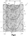
本発明の閉鎖装置タブ要素(14)を提供する別の実施態様が図4に示され、最終端部分(32)上の固着タブ部分(34)の第1端(37)に滑らかな外側側縁(30)が設けられる。閉鎖装置タブ要素(14)は、2つの隣接する最終端部分を分離する切断線の一部(46)から、取付部分を橋絡部分(38)から分離する切断線のオフセット部分(47)へ、切断線パターンが緩徐にテーパする領域(5)を設けることによって、切断パターン(35)に沿ったわずかに修正された形態に切断される。この実施態様において、再度、閉鎖装置タブ要素(14)の実質的に一定な長さ(16)は、閉鎖装置タブ要素(14)の大半を横切って且つ第2部分(33)の幅全体の上に延在する。しかし、固着タブ部分(34)または最終端部分(32)の第1端(37)は長さ方向にテーパする。最終端部分(32)上のテーパした第1端(37)は、図6に示されるように最終端部分の一部を除去することによって、および/または、図8に示されるように適切に嵌まった切断パターンによって、形成されることができる。第1端(37)の湾曲した側縁(30)は、鋭い隅の存在を排除するか減少し、鋭い隅は、皮膚に接触した場合、使い捨て吸収性物品の着用者に不快を起こさせる可能性がある。少なくとも第1固着領域フック材料を含む第1端(37)は、平均長さ(36)を有する。最終端部分(32)の第1端(37)上の固着タブ部分(34)は、使い捨て吸収性物品(91)を形成するのに使用される連続ウェブ(41)の縁(10)を越えて鋭い隅部分が延びないように、設けられることが好ましい。閉鎖装置タブ要素(14)の長さは第1端(37)で変動するため、この実施態様の第1端領域に閉鎖装置ウェブ材料の一定の部分のむだまたは耳を必要とする分岐する切断線が、この領域に必要である。
【0032】
図5は、図4の実施態様の変形例であり、閉鎖装置ウェブ(1)の切断パターンのテーパした領域(5)は、頂部分でわずかに外側に移動した。また、ループ材料(8)および/または繊維のシートが外側に延びており、そのため、最終端部分全体を覆い、それから固着タブ部分(34)が形成される。
【0033】
図6は、図4に示される実施態様に類似したさらなる実施態様を示し、閉鎖装置ウェブ(1)の最終端部分から除去されるべき切断領域または耳(42)が示される。この実施態様において、第2部分(33)の切断線(45)は、略半円取付部分(46)を形成する実質的に連続する弧の形態である。2つの最終端部分(47)を相互接続する橋絡部分(40)は、対応する凹構造である。
【0034】
図7は、本発明によって設計された閉鎖装置タブ要素のさらなる実施態様であり、取付部分(56)は矩形の形状であり、また、第2部分(33)から矩形橋絡要素またはバンドを提供する。別個の閉鎖装置タブ要素(14)がタブ要素切断線(55)に沿って切断され、固着タブ部分に、第1端(17)上の湾曲した縁(30)と、垂直な第2端(18)と、を設ける。
【0035】
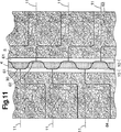
図8に示される実施態様は、複数の最終端部分と第2部分とが設けられた複数幅の閉鎖装置ウェブ上に、固着タブ部分の第1端の丸い縁(30)を製造するための代替例を示す。閉鎖装置ウェブの外側縁の最終端部分で、固着タブ部分の湾曲した側縁(30)が、耳材料を除去することによって依然として設けられる。しかし、中間最終端部分で、2つの嵌まった湾曲した側縁(30)が、図8に示されるように、単一の正弦等の波形切断線によって設けられることができる。図8の実施態様は、結果として、単一の複数幅の一次閉鎖装置ウェブから切断された2つの二次閉鎖装置ウェブ(56)が得られる。2つの二次閉鎖装置ウェブ(56)は、本発明の他の実施態様に開示されているように、同時にまたは順次に、閉鎖装置タブ要素(14)に切断されることができる。
【0036】
図8に示すように、中間の終端部分の曲り側縁は、第1固着領域を有する固着タブ部分の第1端部が何れの無駄な材料または耳もなく重ね合わさるように、単一シヌソイドまたは同様の波形になっている切断線によって提供される。しかしながら、必要ならば、特に、第1固着領域がその幅の寸法の全体にわたり非対称である場合、中間の無駄な領域または耳領域が設けられてもよい。例えば、固着タブ部分の第1端部及び/または第1固着領域の基部は、固着タブ部分の第1端部の外側先端からはっきり区別され、異なっていてもよい。図8の実施態様において、固着タブ部分の第1端部の曲り部分は、連続する第1固着領域が固着タブ部分の第1端部の曲り部分の幅全体にわたり設けられているため、対称である。非対称的な固着タブ部分の第1端部も設けることができる。例えば、第1端部に、機械的固着領域と取付固着領域との組合せなど、2つのはっきり区別された異なった取付領域をその幅に沿って設けることができる。あるいは、第1端部の先端のフィンガーリフト領域などの固着手段を有さない単一領域が設けられてもよいが、同領域は固着タブ部分の第1端部の基部に双方にまたがって設けられない。多幅閉鎖装置ウェブから切り取られたこれら及び他の非対称的な固着タブのデザインは概して、閉鎖装置ウェブの中央部分の2つの隣接した終端部分の第1端部が、各々所望の非対称的な固着タブ部分の第1端部を2つ以上の二次閉鎖装置ウェブ上に提供するように別の切断線を有する必要がある。
【0037】
図9に示した実施態様において、切欠き固着タブ部分の第1端部は閉鎖装置ウェブ上に折り返されているが、それは、閉鎖装置タブ要素の切り取りと同時にまたはその後になされてもよい。固着タブ部分の第1端部は好ましくは、第1端部を第2端部から分離する線に沿って折られるが、第1端部は、取付部分上の嵌め合わせの、第2固着領域に着脱自在に付着するように設計され、第2端部は、使い捨て吸収性物品に永久的に取着するように設計されている。図9の実施態様はまた、第1及び第2固着領域のためにフックアンドループ型機械的固着閉鎖装置を用いて例示されている。
【0038】
図9の実施態様の代替物を図17に示すが、そこにおいて、第1固着領域を設けられた固着タブ部分の第1端部を、第2固着領域の方へではなく離れる方へ折る。この場合、固着タブ部分の第1端部の折られた部分は好ましくは、完全に、固着タブ部分の第1端部の折られていない部分の内側にある。これにより、前記折られた部分が、タブ要素が取着される時、裏地と使い捨て吸収性物品との間に入り込まないことを確実にする。
【0039】
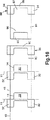
図18は、タブ要素が略シェブロン形である本発明の代替物である。この実施態様は、橋絡要素を有さず、第2部分は、使い捨て吸収性物品上にある時には、略v−形状を有する。
【0040】
図10は本発明の別の実施態様であり、2つの第1固着領域(71)及び(72)が設けられ、両方ともこの場合、フック機械的固着領域であり、一つが終端部分の第1端部(17)にあり、第2第1固着領域が第2部分(33)内の取付部分(60)の外側辺縁(61)にある。終端部分の第1端部(17)に設けられた第1固着領域(71)が裏地の第1面にあり、第2第1固着領域(72)が第2部分(33)上の取付部分(60)に隣接した裏地の第2面に設けられる。
【0041】
図10の実施態様において、前記の2つの第1固着領域(71及び72)は、終端部分の第1端部(17)上の第1固着領域(71)のための取付部分を形成するループ機械的固着材料によって提供される第2固着領域を有するフック機械的固着材料によって提供される。第2部分(33)上に、取付部分(60)に隣接して提供された、第2第1固着領域フック機械的固着材料(72)を、終端部分または固着タブ部分の第2端部(18)に取着した使い捨て吸収性物品の面の反対側の面に提供された、好適なループまたは不織材料と係合し合うように用いることができる。この好適なループまたは不織材料は概して、固着タブ部分の第2端部(18)に取着した物品の前記領域に隣接したまたはすぐ下にある使い捨て吸収性物品の側縁領域上に配置されており、別々に適用されたループ材または不織トップシート型材料であってもよい。
【0042】
概して、上述の実施態様において、閉鎖装置タブ要素の全体的な形状はvまたはu、または同様な形状であるが、しかしながら、w−形状を含めて他の形状が可能である。
【0043】
図11は、終端部分が閉鎖装置ウェブの中央領域に設けられている本発明の別の実施態様を示す。終端部分上の固着タブ部分の第1端部は、図8の実施態様に対して上述したように単一切断線を用いて第1端部の曲り側縁(30)を形成することができるように、図11において対称である。前記固着タブ部分は、固着要素を実質的に含まない領域(61)を提供され、フィンガーリフト領域(62)を提供する。図11の実施態様において、閉鎖装置ウェブから切り取られた2つの向かい合った閉鎖装置タブ要素(63)及び(64)は互いに鏡像であり、一方が、使い捨て吸収被服の一方の縁領域上の固着タブ部分及び取付部分を提供し、向かい合ったタブ要素が、使い捨て吸収性物品の反対側の縁上の向かい合った固着タブ部分及び取付部分を提供する。この実施態様に関しては、2つの分離した、はっきり区別された取付部分(65)及び(66)があり、2つの終端部分または固着タブ部分を連結する橋絡部分またはバンドは存在しない。
【0044】
図12は、どのように図11の閉鎖装置タブ要素(63)及び(64)が、使い捨て物品の一部分を形成する連続ウェブ(41)上に配置され、2つの別々の取付部分(65)及び(66)及び2つの固着タブ部分を提供するかについて例示する。
【0045】
上記の実施態様において示した第1固着領域は、設けられた感圧接着剤層(9)によって裏地(2)に取着した、機械的固着要素、特にフック機械的固着材料(4)によって提供されるが、第1固着領域を他の取付材料によってまたは他の方法で提供することができる。具体的には、第1固着領域は、フックまたはループ機械的固着材料または領域、感圧接着剤領域またはパッチ、凝集接着剤領域またはパッチなどの何れの好適な取付材料であってもよい。好適な嵌め合い係合表面が閉鎖装置ウェブの反対側の面の取付部分の上に設けられる場合、スナップファスナーなどの他の機械的固着タイプの材料も可能である。更に第1固着領域を、図面に示すように、裏地(2)の第1面に取着した別の要素として提供することができ、または裏地(2)と一体に形成することができ、例えば、裏地は、成形されたフック固着要素をその終端部分にだけ設けた押し出しフィルム材料であってもよい。あるいは、第1固着領域は、ホットメルトまたは感圧接着剤(図示)、熱または音波溶接、または他の従来の手段など、好適な方法によって裏地(2)に取着されている別の裏地(6)上に設けられてもよい。
【0046】
第1固着領域が感圧接着剤によって提供される場合、第1固着領域が付く表面は、第2固着領域によって提供された表面である必要はない。例えば、閉鎖装置タブ要素は、第1固着領域がバックシートウェブに、または更にバックシートウェブ上のウェブに付くように、連続バックシートウェブの内面に取着されてもよく、閉鎖装置タブ要素の第2固着領域は、第1固着領域が付く位置でバックシートを強化し、好適なテープ固着領域を形成する。この実施態様において、裏地の第2面は、例えば、内側バックシートウェブの面に付くための好適な感圧接着剤を提供されてもよい。あるいは、裏地の第2面が、先述のように他の取付方法によってバックシートウェブまたは更に別のウェブに付着させられてもよい。
【0047】
閉鎖装置ウェブ(1)のための裏地(2)は、フィルム材料、発泡製品、織または不織ウェブなどの織物、または前述の材料等の何れかまたは全てを含む多層構造体(同多層構造は、裏地(2)の長さ及び/または幅の全体にわたり連続しているか、または断続的であるか、どちらであってもよい)などを含めて何れの好適なウェブ製品または積層体であってもよい。裏地(2または82)は、図13に示した(81)など、特定の弾性領域を有する弾性材料であってもよい。この弾性領域(81)を設けるために、裏地(2または82)の領域に特別に伸縮性をもたせてもよい。図13において、弾性裏地(82)を米国特許第5,505,852号に記載されているように形成するが、米国特許第5,505,852号には、例えば、同特許に記載されているように領域(81)において選択的に延伸することにより、選択的に延伸活性化させて弾性を生じさせる、弾性層(86)及び非弾性層(85及び87)を有する同時押出非弾性多層フィルムが開示されている。しかしながら、代わりに、エラストマーフィルムまたはエラストマー織または不織材料、またはそれらの積層体を、裏地(2または82)として提供するなどによって、裏地(2または82)全体を弾性にしてもよい。図13において、フック固着材料(4)は、フック材(4)上または裏地(82)上に設けられるかまたは被覆されてもよい接着剤層(89)によって裏地(82)の非弾性部分に取着される。
【0048】
フィルム裏地上に弾力ゾーン(81)を提供する代わりの方法を図15に示す。図15において、フィルム裏地は選択的な並行する弾性領域と非弾性領域、例えば、特願平8−187113(Japanese Appln.No.8−187113)に開示されている弾性材料と非弾性材料の並行する同時押出によって形成される。あるいは、並行する弾性および非弾性領域は、米国特許第5,429,856号に開示されている非弾性母材内に含まれる弾性領域によって提供され得る。
【0049】
弾性裏地材料(12または82)もまた、非弾性フィルムまたはその他のウェブ材料に伸張されていない状態で選択的に結合または積層され、続いて複合材料を選択的に伸張して米国特許第5,167,897号、同第5,156,793号、同第5,143,679号、または同第5,527,304号、または国際特許出願第96/1048号(伸張は非弾性層を選択的にスリットすることによって促進される)に開示される弾力を提供するか、弾性材料は別々の裏地層(例えば、不織ウェブ)に伸張された状態で断続的にまたは連続して取着することによって適用され、そのように形成された積層裏地の積層裏地材料となって回復するようにし、その領域において弾性複合材料を形成し取着ポイントの間で収縮するか、またはしわ(buckle)になる。別々に適用された弾性材料もまた、弾性または非弾性であり得る別の連続裏地材料の第1または第2面のいずれかに適用されてもよく、弾性材料に取着するときに、その他の連続裏地は伸張されたり伸張されなかったり、収縮されたり波形を付けられたりしてもよい。
【0050】
ループ材(8)または(88)は、従来技術において周知であるように、裏地(2)または(82)に好適に取着される従来の織物または不織ループ材のいずれであってもよい。
【0051】
図14は、本発明の代わりの実施態様を示し、ループ布帛が領域(83)においてフック材と係合可能であるように選択的に提供され、一般に領域(84)におけるフック材との係合より係合し難い。ループ布帛はフィルム裏地(82)に適用される。これは、比較的嵩高の低い不織タイプの布帛を使い、領域(81)において選択的に収縮または波形を付けるようにし、所望により更に強固にされ得る領域(84)においては実質的に平らにすることによって達成される。これは、ウェブ(3)に波形または起伏を、その領域または閉鎖装置ウェブの第2面の取付部分を形成する第2部分にのみ、選択的に提供することにより図3において示された方法を使用することにより達成され得る。ループ材を形成するのに好適な不織材料は、例えば、米国特許第5,256,231号、同第5,614,281号、同第5,032,122号、同第5,470,417号、同第5,326,612号、国際特許出願第96/04812号、同第95/33390号に開示されている。
【0052】
図15は、裏地(107)が並行同時押出され、弾性領域(105)のいずれかの側に非弾性領域(104または106)を有する代わりの実施態様を示す。更に、非弾性領域(106)は一体的なフック型要素が形成される。伸張できないウェブ(103)を裏地の第1面に取着し、少なくとも弾性領域(81)において図3に示す方法によって波形を付け、あるいは従来技術に示されるように幅を圧縮する。裏地の第2面は、図3に示す方法によって全幅にわたって波形を付けたループ材(108)を備え、弾性領域(8)を伸張し実質的にループ型の取付部分を提供する。
【0053】
本発明により、使い捨て吸収性物品の一部を形成することができる少なくとも1つの連続するまたは実質的に連続するウェブを提供するステップを含む、使い捨て吸収性物品用閉鎖装置の形成方法がさらに得られる。このウェブは2つの側縁を規定する少なくとも第1幅および不定長さを有する。閉鎖装置ウェブは、第1面と第2面とを有する少なくとも1つの裏地も備える。閉鎖装置ウェブは、第1幅よりも広い第2幅および確定されない長さを有する。閉鎖装置ウェブの第1面は、少なくとも1つの第1固着領域を閉鎖装置ウェブの少なくとも1つの末端部分に備える。少なくとも1つの第2固着領域が第1固着領域を備える末端部分に隣接する少なくとも第2部分において閉鎖装置ウェブの第2面に提供される。閉鎖装置タブ要素は、タブ要素が確定長さを有する閉鎖装置ウェブから切断される。閉鎖装置タブ要素は、少なくとも1つの固着タブ部分を有し、少なくとも1つの固着領域を末端部分に含み、取付部分が第2固着領域を有する第2部分を含む。
【0054】
次いで閉鎖装置タブ要素は少なくとも1つの連続するまたは実質的に連続するウェブに等間隔を置いて不定長さに第2連続ウェブを形成する連続方法で取着される。次いで第2連続ウェブは、横切断線に沿って不定長さに切断される。切断線は、固着タブ部分が切断線の第1の側にあり、取付部分が切断線の第2対向する側にあるように、タブ要素の確定長さに沿って閉鎖装置タブ要素を2分する。これにより、1つの吸収性物品の第1端の固着タブ部分および隣接する吸収性物品の第2端の取付部分が得られる。また、横切断線が個々の吸収性物品を形成するのが好ましい。
【図面の簡単な説明】
【図1】 本発明に使用される閉鎖装置ウェブの第1実施態様の側断面図である。
【図2】 図1に示されたような閉鎖装置ウェブの一部の切欠上斜視図である。
【図3】 図1、2に示されたような本発明の閉鎖装置ウェブを形成する装置の切欠概略図である。
【図4】 本発明による閉鎖装置ウェブの第2実施態様の上斜視図である。
【図5〜7】 本発明による閉鎖装置ウェブの3つのさらなる実施態様の上斜視図である。
【図8】 2倍の幅を有する本発明による閉鎖装置ウェブのさらなる実施態様の上斜視図である。
【図9】 本発明による閉鎖装置ウェブのさらなる実施態様の上斜視図である。
【図10】 本発明による閉鎖装置ウェブのさらなる実施態様の上斜視図である。
【図11】 本発明によるさらなる閉鎖装置ウェブの上斜視図である。
【図12】 使い捨て吸収性物品を形成するウェブ41に加えられるときの図11の実施態様の上斜視図である。
【図13〜15】 本発明による閉鎖装置ウェブのさらなる実施態様の側断面図である。
【図16】 本発明の閉鎖装置ウェブが、連続ウェブ41からどのように切断されて使い捨て吸収性物品の形成にタブ要素として加えられるかの概略斜視図である。
【図17】 本発明による閉鎖ウェブのさらなる実施態様の上斜視図である。
【図18】 本発明による閉鎖ウェブのさらなる実施態様の上斜視図である。[0001]
Background and field of the invention
The present invention relates to a closure device for a disposable absorbent article, and more particularly to a multifunction closure device that can be attached to a waistband portion of a disposable absorbent article.
[0002]
In the field of disposable absorbent articles, typically in the field of disposable diapers and adult incontinence articles, a closure device is usually provided that is formed using a pressure sensitive adhesive securing tab or a mechanical securing tab. These tabs are typically attached to disposable absorbent articles at the corners, for example at least one end of an article such as a diaper. A typical securing tab has one end permanently coupled to the absorbent article and a second free end available for the user to removably attach to the opposite end of the article to effect closure. And have. The opposing ends of the absorbent article are generally provided with a mating mounting surface. In the case of pressure sensitive adhesive securing tabs, the mating attachment surface is typically a reinforcing film or other material applied to the inner or outer surface of the outer liquid impervious layer of the disposable absorbent article. In the case of a mechanical anchoring tab, the mating attachment surface is a loop anchoring material that must be located on the outer surface of the liquid-impermeable outer cover layer of the disposable absorbent article. In either case, the mating mounting surface is generally provided by adding a discrete discrete element to the absorbent article. This may be a pressure sensitive adhesive element or it may be an adhesiveless element joined by other means such as hot melt adhesive or heat welding. In extreme cases, the entire outer surface of the disposable absorbent article can be provided with a suitable mating mounting surface for the second free end of the anchoring tab, but this is overly expensive. The anchoring tab itself is also applied as a separate discrete element in the corner of the disposable absorbent article, usually in the rear end region. In general, this permanent attachment of the anchoring tab is accomplished by a pressure sensitive adhesive applied to one end of the anchoring tab, and the other second end of the anchoring tab is the peelable attachment of the absorbent article. And a suitable pressure sensitive adhesive or mechanical fastening element for closure. The anchoring tab can be added as a separate piece cut from a roll that can be laminated with other suitable materials, such as a release tape, during manufacture of the diaper. Alternatively, the securing tab may be provided with other suitable components in pre-laminated form that are also cut from the continuous roll. These closure devices are highly effective, but can be complex, especially when laminated to a diaper line and / or when additional functionality such as elasticity is incorporated into the anchoring tab.
[0003]
It has also been proposed in the patent literature that suitable belt means are provided with attachment elements at both ends of the belt to provide a closure device for use in disposable absorbent articles. The belt can address some of the problems with separate tab fasteners, but requires the use of a single laminate or the like that can be fixedly or releasably attached to a diaper absorbent pad or the like Some things just do. However, it has also been proposed to use two interconnect belts. In U.S. Pat. Nos. 3,847,702 and 3,561,446, an unstretchable belt material is provided at both the front and rear ends of the disposable diaper. Each belt extends across the full width of the diaper and both belts are provided with a pressure sensitive adhesive area at the end and this adhesive is covered with release tape until used. When the diaper is closed, one belt is attached to a portion of the second belt at the opposite end of the diaper, and the adhesive at the end of the second belt is generally provided with the first belt in the diaper. It is attached to the diaper side opposite to the one. These belts prevent inelastic deformation of the waistband area of the diaper during use. However, the two belt devices are similar to the use of tab fasteners in terms of complexity of manufacture.
[0004]
French Patent Nos. 2,585,558, 2,725,879, and International Patent Application No. 94/26224 teach that only one non-stretchable belt is used. Can be attached to the front or back of the diaper, either permanently or by a refastenable mechanical fastening element. When the diaper is refastened to the belt, the belt can be reused repeatedly. In these patent documents, the belt is usually wrapped around the wearer and is releasably attached to the belt at least at one end of the diaper and is releasable or permanently attached to the belt at the opposite end of the diaper. Secure yourself with the diaper to be worn. A similar approach was proposed in US Pat. No. 4,964,860 and International Patent Application No. 91/08725, where reusable belts with mechanical fastening elements are used, and meshing mechanical fastening elements for disposable diapers Is provided. These belts are relatively easy to incorporate into a diaper, but lack the ease of use of the fastener tab closure device by the end user.
[0005]
In European Patent Application No. 528282, a permanent integrated waistband is provided on the diaper, which can be stretched. The waistband is at one end of the diaper and wraps around the wearer's waist and attaches to the waist itself to form a belt. Both the waistband and the front portion of the diaper are provided with suitable
[0006]
In US Pat. No. 5,593,401, a bridging element is provided as a separate element in one end region of the diaper, whereas two conventional fastening tabs may be attached on both sides. . The bridging strip is described as having a fixed side and an unattached side and is usually elastic. This bridging strip requires a separate attachment step and associated equipment in order to be integrated into the disclosed conventional diaper structure. This is similar to the two belt devices described above, but is more complex in terms of structure and manufacture.
[0007]
Elastic waist elements that are attached to the securing tabs and then releasably attached to the front panel portion of the diaper are disclosed in US Pat. No. 4,998,929 and International Patent Application Publication No. WO 96 / No. 32083 and International Patent Application Publication No. WO 95/22951. An elastic belt element wrapped around the wearer's waist and provided with an interengaging mechanical fastening element at the end is disclosed in US Pat. No. 5,607,416. In all the above patent documents, there is a separate, discriminating elastic element, and the final end typically includes a mounting element such as a pressure sensitive adhesive or a mechanical fastening element, which is described in US Pat. No. 5,607,416. Attach to an elastic belt according to No. or to a suitable attachment mechanism on the other end portion of a diaper or similar disposable absorbent article.
[0008]
The use of two or one belt closure devices, each wrapping one end of the diaper or the entire wearer's waist, is desirable from a number of perspectives. The belt can be used in the closure device to provide other functions such as resiliency or non-stretchability that are firmly integrated into the closure device. However, the means proposed to provide these belts and closure elements generally require a number of separate attachment steps in the manufacturer's line.
[0009]
The present invention can provide an effective closure device with a single attachment step that can provide additional desired functionality such as non-stretchable belt elements, stretchable belts or bands, elastic rubber, etc. In particular, it relates to addressing the manufacturing complexity of multi-component closure devices. The present invention also relates to a method for providing a diaper closure device, and optionally to a belt device for a diaper line by using a single closure device laminate.
[0010]
Disclosure of the invention
The present invention includes a closure device and a method of forming a closure device for a disposable absorbent article. That is, the present invention is a method for forming a closure device for a disposable absorbent article, which can form a part of a disposable absorbent article and has a first width dimension and an indefinite length dimension that define two side edges. Providing at least one continuous web; and a first side And Providing a closure device web having at least one liner having a second surface and having a second width dimension and an indefinite length dimension, wherein the first surface comprises at least one first anchoring region; Providing a closure device web comprising at least one end portion in the side edge and middle of the closure device web, the second surface comprising at least one second anchoring region in the second portion adjacent to the termination portion; Cutting the closure device web to form a plurality of closure device tab elements each having a defined length dimension, each of the closure device tab elements being at least one first fastening of the terminal portion. At least one securing tab portion comprising a region and a mounting portion comprising a second securing region of the second portion, wherein the at least one securing tab portion is a fixed length from the mounting portion. Forming a plurality of closure device tab elements, and having a first width dimension of at least one continuous web, equally spaced in the direction of an indefinite length of the at least one continuous web Installing a plurality of closure device tab elements in position Each closure such that at least one anchoring tab portion protrudes from a side edge of the at least one continuous web and the attachment portion forms a second anchoring region on the at least one continuous web. Attaching the device tab element to at least one continuous web Cutting at least one continuous web along a plurality of transverse cutting lines, each of the transverse cutting lines separating each of the plurality of closure device tab elements along its defined length in two minutes. The at least one securing tab portion is on the first side of the transverse cutting line and the attachment portion is on the second side opposite the transverse cutting line, thereby And a continuous web cutting step adapted to provide a securing tab portion at one end and an attachment portion at a second end of another adjacent absorbent article.
[0012]
The present invention also includes a first width dimension that defines two side edges; in front Edge And trailing edge Disposable absorbent article having Used in Closing device, first side And Lining with second side With opposite each other in front edge And And Trailing edge Having at least one fastening tab portion Because The second One side In First fixing area With Ru At least one Fastening tab portion When, Having a first side and a second side lining With opposite each other in front edge And And Trailing edge At least one mounting part having , On the second side With two anchoring areas At least one An attachment portion, At least one securing tab portion is formed to be disposed protruding from the side edge of the disposable absorbent article, At least one mounting part Before edge But Of disposable absorbent articles Front without protruding from the front edge Extends laterally along the edge Formed to , The trailing edge of the at least one securing tab portion is formed to extend laterally from the trailing edge without extending past the trailing edge of the disposable absorbent article and parallel to the leading edge of the at least one attachment portion. At least small At least one securing tab The trailing edge of the part Contained area And a little At least one mounting part The leading edge of Contained area When In , That Each Behind The ground is made of the same material, Used in disposable absorbent articles Providing a closure device.
[0013]
DESCRIPTION OF PREFERRED EMBODIMENTS
The present invention relates to providing a fully functional closure device for a disposable absorbent article and is integrated with a method of forming a disposable absorbent article by attachment of an integral closure device tab element. The tab element is cut from the continuous closure device web product and then attached to the continuous or substantially continuous absorbent article web, and the discontinuous disposable absorbent article is finally cut. These closure device tab elements provide both a fastening tab for a disposable absorbent article and a suitable mating mounting surface. However, the fastening tabs and mating attachment surfaces of a single closure device tab element terminate with a different absorbent article when the absorbent article is cut from the absorbent article web.
[0014]
A first embodiment of a closure device web product is shown in cross-section in FIG. 1, which comprises a laminate of a backing layer (2) having a first side provided with a pressure sensitive adhesive layer (9). The pressure sensitive adhesive layer (9) is used to finally attach the closure device tab element to the disposable absorbent article web. A first anchoring area is attached to the backing (2) at the end portion. In the embodiment of FIG. 1, the first anchoring area is provided by a hook mechanical anchoring material (4) formed from a hook mechanical anchoring element (7) protruding from a hook backing (6). However, the anchoring area can be formed directly on the backing (2) rather than being attached as a separate element, for example by using an adhesive as shown in FIG. The second side of the backing (2) in FIG. 1 is provided with a second anchoring region comprising an interlocking loop mechanical anchoring material (8), which engages the hook mechanical fastener material (4). These two interlocking fastening materials together form an integral closure device when added to a diaper web or the like in accordance with the present invention.
[0015]
The closure device tab element (14) is cut from the continuous closure device web (1) along the cutting line (15) as shown in FIG. The closure device web (1) and the closure device tab element (14) cut therefrom have a width dimension (31) divided into a final end portion (32) and a second portion (33). The final end portion (32) may be on the side edge of the closure device web, as shown in FIG. 2, or it may be provided in the middle region of the closure device web, as shown in FIGS. Good. The closure device web (1) typically has an indefinite length direction (L), but the closure device tab element (14) cut from the web (1) typically has a defined length dimension (16). This is preferably constant over most of the width (31) of the closure device tab element (14) and preferably at least over the entire second portion (33).
[0016]
If the closure device tab element (14) varies in length (16) across its width, two separate cutting lines must be provided to define the top and bottom of adjacent closure device tab elements. . This requires a waste or ear of material between two separate cutting lines. If a single tab element cut line defines both the top and bottom of two adjacent tab elements (14), the length of the tab element (16) is Constant across the width of the tab element along the shared boundary defined by the line (the special case that the tab element cutting line is parallel to the length, in which case the width includes the length of the cutting line except). Inevitably, however, the tab element cutting line is not a straight line and varies in the length direction of the continuous web, so that the final end portion (32) deviates in length from the second portion (33). The average deviation is at least 10 percent and preferably at least 50 percent of the maximum length of the final end portion.
[0017]
The final end portion (32) is usually provided with a first anchoring area, which in the case of FIG. 2 is a hook mechanical anchoring material (4), which is attached to the second part (33). The meshing part engages the second loop mechanical anchoring material (8). In FIG. 2, the second anchoring area forming the attachment part is the loop material (8).
[0018]
The closure device tab element (14) is a continuous or substantially continuous web used to form an absorbent article at a position having the first width when cut from the closure device web (1). To provide an integral structure to be attached. As can be seen in FIG. 16, the outer backsheet web of the diaper can be formed from a continuous web. As shown in FIG. 16, the continuous web is either assembled or will be assembled from it, and other components form a continuous disposable absorbent article web. A discontinuous disposable absorbent article is cut from the disposable absorbent article web. For example, these other components may include, in addition to the backsheet web, an absorbent batt material, a fluid permeable top sheet, a fluid transport layer or similar continuous or substantially continuous web elements. These can be conventionally integrated into the manufacture of disposable absorbent articles. Also, other discontinuous elements can be attached to the continuous web, such as additional tab elements, elastic rubber such as leg or waist elastic rubber, liquid barrier layers, reinforcing elements, and the like.
[0019]
As shown in FIG. 16, the continuous web is a backsheet web, but other continuous webs can be used for attachment of the closure device tab elements, such as nonwoven cover sheets, liquid permeable elements, etc. It is. Also, the continuous or substantially continuous web to which the closure device tab element is attached may be non-planar, laminated to other webs, or of a plurality of discontinuous components It may be a composite material made by lamination. It is also possible to use a substantially continuous web having discontinuous short regions, at least in the region where the closure device tab element is attached, usually creating a web element that is arranged sequentially and supported continuously. However, in this embodiment, when the closure device tab element is attached to a discontinuously supported web element, the web element and the attached closure device tab element are at least a closure device tab element. A continuous web is formed in the region between where the web is attached and where the discontinuous absorbent article is cut and / or where the closure device tab element is bisected.
[0020]
In FIG. 2, the reference numeral (10) indicates the side edge of the continuous web (41) of at least one absorbent article, whereas the closure device tab element (14), as shown in FIG. At least one absorbent article is attached at a discontinuous longitudinally displaced position along the length of the continuous web (41). The continuous web (41) is then cut into a discontinuous absorbent article along a transverse cut line, which is typically a closure device tab element (as shown in FIGS. 2, 16, for example). 14) Divide into two equal parts or cut. However, for example, by halving the closure tab elements as part of a continuous web, attaching these discontinuous elements to a further web, from which the discontinuous absorbent article is finally formed It is possible to bisect the closure device tab element before cutting the discontinuous absorbent article. When the discontinuous absorbent article is cut, a portion of the second end (33) that forms the final end portion (32) and the bridging element or band (95 or 12) is the first disposable absorbent article. It remains attached to (90) and most of the second part (33) is on the adjacent disposable absorbent article (91), forming the attachment part (93 or 13).
[0021]
The final end portion (32) remains permanently attached to the first end (17) projecting outward beyond the side edge (10) of the disposable absorbent article and the disposable absorbent article web (41). Having a second end (18). At least a portion of the first end (17) includes a first anchoring region, such as the hook material (4) of FIG. The intermeshing loop material (8) of the attachment portion (93 or 13) of the second part (33) meshes with the adjacent absorbent article (91) when attached to the continuous web (41). Which, together with the final end portion (32) of the next down web closure device tab element, forms an integral closure device on the disposable absorbent article (90).
[0022]
Generally, the attachment portion (93) is attached to a front region (96) such as a disposable absorbent article. The final end portion (32) including the first anchoring region is attached to a rear portion (97) such as a disposable absorbent article. However, the front and rear portions are determined by how the article is attached, which can be determined by the user. As such, the front portion can also be used as the rear portion if the absorbent article is substantially symmetrical and the user chooses to do so.
[0023]
The final end portion (32) is generally provided only on the first side of the transverse cutting line (11) and forms a fastening tab portion (99) on the disposable absorbent article. These securing tab portions can be interconnected or include a portion of the second portion (33), as shown in FIGS. A bridging portion or band (12 or 95) around the front or back peripheral edge of the disposable absorbent article (91) when these portions of the second portion (33) interconnect the two securing tab portions Acts as Thus, when the fastening tab portion (99) is attached to the attachment portion (13 or 93), a continuous band is formed around the disposable absorbent article formed by the front portion (96) and the rear portion (97). Formed around the edge. This bridging portion or band (12 or 95) is non-extensible, extensible and / or elastic, in whole or in part, depending on the material forming the backing layer (2).
[0024]
If an appropriate backing (2) is selected, the bridging element or band (12 or 95) can provide functionality such as non-stretchability. Non-stretchable is desirable because garments such as diapers can be permanently stretched when worn. This elongation results in a loose fit and can leak or even drop the diaper. If a continuous non-stretchable band is provided around the diaper, this elongation is minimized or eliminated. The elasticity of the bridging element (12 or 95) can also cope with stretch by tightly engaging around the wearer's waist, providing an elastic recovery force. In this case, all or part of the backing (2) is made elastic and the closure device tab element (14) is applied in a conventional manner for a waist elastic rubber or similar elastic rubber component.
[0025]
FIG. 16 schematically shows a continuous web of disposable absorbent article web (41) to which a closure device tab element (14) as shown in FIGS. The disposable absorbent article (100) cut from the web (41) when the final end portion (32) is cut from the attachment portion (93 or 13) of the second portion (33) by the transverse cutting line (11). 91) at the final side edge (10), two fastening tab portions (99) connected by bridging elements (95) are formed. The attachment part (13 or 93) of the second part (33) meshes to form a second attachment region of the attachment attachment surface, to which the first attachment region of the attachment tab part (99) is attached. The transverse cutting line (11) is such that the fastening tab portion (99) and the bridging element (12 or 95) are on one side of the transverse cutting line (11) and the attachment portion (13 or 93) is The closure device tab element (14) is bisected along its defined length dimension (16) so that it is on the two opposite sides. An integral closure device connects each securing tab portion (99) on the first side of the transverse cutting line of the first closure device tab element (14) to the second of the adjacent second closure device tab element (14). Formed into a single disposable absorbent article (91) by combining with adjacent attachment portions (93) cut from opposite sides.
[0026]
In general, the maximum length of the anchor tab portion is 2-10 cm long, preferably 2-5 cm, and 2-20 cm wide, preferably 5-15 cm, based on the dimensions of the article. However, the first anchoring area may have an average length of 0.5 to 5 cm, preferably 1 to 4 cm, or 0.25 to 25 cm. 2 , Preferably 1-10cm 2 May be arranged so as to give a cross-sectional area of The portion of the securing tab portion that is permanently attached to the article includes the second end of the final end portion (32) and may include the second portion (33). Generally, the minimum width of the second end of the fastening tab portion (99) permanently attached to the diaper is 1-5 cm, preferably 2-4 cm.
[0027]
The overall length of the attachment portion (13 or 93) is preferably at least 40 to 95 percent, preferably 60 to 90 percent of the first anchoring area. The length of the bridging element may vary across its width, as is the length of the attachment portion. The average length of the attachment portion is 5 to 100 cm, preferably 10 to 50 cm. In general, the maximum length (16) of the closure device tab element can vary as needed and is between 10 and 200 cm, preferably between 20 and 100 cm. The length of the bridging member may be zero or close to zero, in which case it does not provide functionality as a continuous belt element. However, if the bridging element functions as an elastic rubber band or a non-stretchable band or the like, the minimum length is usually at least 0.5 cm, and usually at least 1 cm to 5 cm. The average length of the bridging elements is less than 40 percent of the average length of the attachment portion. If the bridging element and the attachment part are joined, they usually form a rectangular shape, at which time the tab elements are separated by a single cutting line in the second part. As such, the bridging element and the attachment portion are usually negative mirror images of each other.
[0028]
FIG. 3 illustrates the closure device web of FIGS. 1 and 2 having hook and loop anchoring areas using a method substantially as described in US Pat. No. 5,256,231 to form a loop anchoring area. The method for forming is illustrated. By this method, a sheet of fibers (3), which may be a nonwoven web, used to form the loop material (8) is formed into a web by conventional means, for example from a feed roll or directly. The process feeds between a pair of mutually parallel meshing rollers (25, 26) provided with meshing teeth. These teeth mesh like gear teeth and the ridge of one roll fits into the valley of the other roll, and vice versa. As shown in FIG. 3, these meshing teeth are easily aligned along the length of the rollers (25, 26), but these teeth are in many other regular meshing patterns. Can also be arranged, for example, extending the teeth circumferentially along the diameter of the rollers (25, 26) or, for example, diamonds, hexagons, squares, circles or any other regular or It is a meshing shape pattern such as an irregular pattern, where the peak portion of the pattern on one roll meshes with the valley portion of the pattern of the adjacent roll. Upon exiting the nip (24) formed by the rolls (25, 26), the sheet of fibers, for example, applies web tension, vacuum, heats the roll (26) differently and / or rolls ( It is held along the circumference of the roll (26) by roughening the surface of 26). In this regard, the fiber sheet (3) is maintained in its deformed or wavy state and joined with a dimensionally stable web material such as a film or a dimensionally stable woven or non-woven fabric. This provides dimensional stability. Alternatively, the sheet of corrugated fibers can be made elastic or stretchable by joining the web material to an elastic or stretchable web material that can form a closure device web backing (2).
[0029]
As shown in FIG. 3, the wavy loop material (8) held on the surface of the roll (26) is directly on the melt-extruded film material (23) formed by the die provided with the die opening (22). Be joined. The extruded film material (23), still in the molten or semi-molten state, is sufficiently soft that the corrugated sheet of fiber (3) on the roll (26) can be embedded in the extruder. This provides a fixed bond and also provides dimensional stability and other properties based on the properties of the film backing (23) and any additional layers provided (not shown). The backing roll (27) forms a nip with the roll (26), which is generally a cooled smooth roll. The nip pressure is preferably substantially constant across the width of the laminated web material formed by at least the sheet of corrugated fibers (8) and the extruder (23). Additional cooling rollers may be provided or, if desired, the laminate may be further wound around rollers (27) to provide further cooling. The laminate backing (2) is then further applied with an adhesive (9) using an adhesive coater (29), which may be a pressure sensitive adhesive. An adhesive (9) can be used to bond the mechanical fastening material (4) to the backing (2) with an adhesive. The mechanical anchoring material (4) may be pre-applied with an adhesive and bonded with a laminated web backing (2) or attached by other mechanisms including sonic bonding, point bonding, stitching, etc. Also good.
[0030]
If a preformed web material is provided as the backing (2), the nip (28) formed between the rolls (26 and 27) can be, for example, an oil heated roller, a water heated roller, It is preferred that the roll (26 or 27) be provided with a heating element, such as an induction heated roll or an ultrasonic horn, so that the fiber sheet (8) is heated to thermally bond to the preformed backing material. .
[0031]
Another embodiment for providing the closure device tab element (14) of the present invention is shown in FIG. 4 with a smooth outer side on the first end (37) of the anchor tab portion (34) on the final end portion (32). An edge (30) is provided. The closure device tab element (14) is from a part of the cutting line (46) separating two adjacent final end parts to an offset part (47) of the cutting line separating the attachment part from the bridging part (38). By providing a region (5) where the cutting line pattern tapers slowly, it is cut into a slightly modified form along the cutting pattern (35). In this embodiment, again, the substantially constant length (16) of the closure device tab element (14) extends across the majority of the closure device tab element (14) and over the entire width of the second portion (33). Extending over. However, the anchor tab portion (34) or the first end (37) of the final end portion (32) tapers in the length direction. The tapered first end (37) on the final end portion (32) is suitably removed by removing a portion of the final end portion as shown in FIG. 6 and / or as shown in FIG. It can be formed by a fitted cutting pattern. The curved side edge (30) of the first end (37) eliminates or reduces the presence of a sharp corner, which can cause discomfort to the wearer of the disposable absorbent article when in contact with the skin. There is sex. The first end (37) including at least the first anchoring area hook material has an average length (36). The securing tab portion (34) on the first end (37) of the final end portion (32) extends beyond the edge (10) of the continuous web (41) used to form the disposable absorbent article (91). It is preferable that the sharp corner portion is not extended. Because the length of the closure device tab element (14) varies at the first end (37), a bifurcated cut requiring a waste or ear of a portion of the closure device web material in the first end region of this embodiment. A line is required in this area.
[0032]
FIG. 5 is a variation of the embodiment of FIG. 4 wherein the tapered region (5) of the cutting pattern of the closure device web (1) has moved slightly outward at the top. Also, the loop material (8) and / or the sheet of fiber extends outwardly, so that it covers the entire final end portion, from which the fastening tab portion (34) is formed.
[0033]
FIG. 6 shows a further embodiment similar to the embodiment shown in FIG. 4, showing the cutting area or ear (42) to be removed from the final end portion of the closure device web (1). In this embodiment, the cutting line (45) of the second part (33) is in the form of a substantially continuous arc that forms a generally semicircular mounting part (46). The bridging portion (40) interconnecting the two final end portions (47) is a corresponding concave structure.
[0034]
FIG. 7 is a further embodiment of a closure device tab element designed in accordance with the present invention, wherein the attachment portion (56) is rectangular in shape and provides a rectangular bridging element or band from the second portion (33). To do. A separate closure device tab element (14) is cut along the tab element cut line (55), and the anchor tab portion has a curved edge (30) on the first end (17) and a vertical second end ( 18).
[0035]
The embodiment shown in FIG. 8 is for producing a rounded edge (30) of the first end of the anchoring tab portion on a multi-width closure device web provided with a plurality of final end portions and a second portion. An alternative example is shown. At the final end portion of the outer edge of the closure device web, the curved side edge (30) of the anchoring tab portion is still provided by removing the ear material. However, at the middle end portion, two fitted curved side edges (30) can be provided by a corrugated cutting line such as a single sine as shown in FIG. The embodiment of FIG. 8 results in two secondary closure device webs (56) cut from a single multi-width primary closure device web. The two secondary closure device webs (56) can be cut into closure device tab elements (14) simultaneously or sequentially, as disclosed in other embodiments of the invention.
[0036]
As shown in FIG. 8, the curved side edge of the middle terminal portion is a single sinusoid or a single sinusoid so that the first end of the anchor tab portion having the first anchor region overlaps without any wasted material or ears. Provided by a cutting line having a similar waveform. However, if necessary, an intermediate waste area or ear area may be provided, particularly if the first anchoring area is asymmetric across its width dimension. For example, the first end of the anchoring tab portion and / or the base of the first anchoring region may be distinct and different from the outer tip of the first end of the anchoring tab portion. In the embodiment of FIG. 8, the bent portion of the first end of the anchoring tab portion is symmetrical because a continuous first anchoring region is provided over the entire width of the bent portion of the first end of the anchoring tab portion. is there. A first end of the asymmetric anchor tab portion can also be provided. For example, the first end can be provided with two distinct and distinct attachment areas along its width, such as a combination of mechanical and attachment fixation areas. Alternatively, a single region having no fixing means such as a finger lift region at the tip of the first end portion may be provided, but the same region is provided across the base of the first end portion of the fixing tab portion. I can't. These and other asymmetrical fastening tab designs cut from the multi-width closure device web generally have a first end of two adjacent end portions of the central portion of the closure device web, each of which has the desired asymmetrical fixation. It is necessary to have a separate cut line to provide the first end of the tab portion on two or more secondary closure device webs.
[0037]
In the embodiment shown in FIG. 9, the first end of the notch securing tab portion is folded over the closure device web, but it may be made simultaneously with or after the closure device tab element is cut. The first end of the anchor tab portion is preferably folded along a line separating the first end from the second end, the first end being a second anchor region of the mating on the mounting portion. The second end is designed to be permanently attached to the disposable absorbent article. The embodiment of FIG. 9 is also illustrated using a hook and loop type mechanical fastening closure device for the first and second fastening regions.
[0038]
An alternative to the embodiment of FIG. 9 is shown in FIG. 17, where the first end of the anchoring tab portion provided with the first anchoring area is folded away toward the second anchoring area rather than toward the second anchoring area. In this case, the folded portion of the first end of the fastening tab portion is preferably completely inside the unfolded portion of the first end of the fastening tab portion. This ensures that the folded portion does not penetrate between the backing and the disposable absorbent article when the tab element is attached.
[0039]
FIG. 18 is an alternative to the present invention where the tab element is generally chevron shaped. This embodiment has no bridging elements and the second portion has a generally v-shape when on a disposable absorbent article.
[0040]
FIG. 10 is another embodiment of the present invention, where two first anchoring areas (71) and (72) are provided, both in this case hook mechanical anchoring areas, one of the first of the end portions. At the end (17), the second first anchoring region is at the outer edge (61) of the mounting portion (60) in the second portion (33). The first fixing region (71) provided at the first end (17) of the terminal portion is on the first surface of the backing, and the second first fixing region (72) is a mounting portion on the second portion (33). (60) provided on the second surface of the lining adjacent to.
[0041]
In the embodiment of FIG. 10, the two first anchoring areas (71 and 72) form a loop that forms a mounting part for the first anchoring area (71) on the first end (17) of the terminal part. Provided by the hook mechanical anchoring material having a second anchoring area provided by the mechanical anchoring material. On the second part (33), the second first anchoring area hook mechanical anchoring material (72) provided adjacent to the attachment part (60) is applied to the second end ( It can be used to engage with a suitable loop or non-woven material provided on the face opposite the face of the disposable absorbent article attached to 18). This suitable loop or nonwoven material is generally disposed on the side edge region of the disposable absorbent article adjacent to or just below the region of the article attached to the second end (18) of the anchor tab portion. It may be a separately applied loop material or non-woven topsheet type material.
[0042]
In general, in the embodiments described above, the overall shape of the closure device tab element is v or u, or a similar shape, however, other shapes are possible, including the w-shape.
[0043]
FIG. 11 shows another embodiment of the invention in which the end portion is provided in the central region of the closure device web. The first end of the securing tab portion on the terminal portion can be formed with a curved edge (30) of the first end using a single cut line as described above for the embodiment of FIG. Further, it is symmetric in FIG. The anchor tab portion is provided with an area (61) substantially free of anchor elements and provides a finger lift area (62). In the embodiment of FIG. 11, two opposing closure device tab elements (63) and (64) cut from the closure device web are mirror images of each other, one being a securing tab on one edge region of the disposable absorbent garment. Providing a portion and an attachment portion, the opposing tab elements provide an opposing securing tab portion and attachment portion on the opposite edge of the disposable absorbent article. For this embodiment, there are two separate and distinct attachment portions (65) and (66), and there is no bridging portion or band connecting the two end portions or the fastening tab portions.
[0044]
FIG. 12 shows how the closure device tab elements (63) and (64) of FIG. 11 are placed on a continuous web (41) that forms part of a disposable article and two separate attachment portions (65) and (66) and how to provide two anchor tab portions.
[0045]
The first fastening area shown in the above embodiment is provided by a mechanical fastening element, in particular a hook mechanical fastening material (4), which is attached to the backing (2) by means of a pressure sensitive adhesive layer (9) provided. However, the first anchoring region can be provided by other attachment materials or in other ways. Specifically, the first anchoring region may be any suitable attachment material such as a hook or loop mechanical anchoring material or region, a pressure sensitive adhesive region or patch, a cohesive adhesive region or patch. Other mechanically anchored types of materials such as snap fasteners are possible if a suitable mating engagement surface is provided on the mounting portion on the opposite side of the closure device web. Furthermore, the first anchoring area can be provided as a separate element attached to the first side of the backing (2), as shown in the drawing, or can be formed integrally with the backing (2), for example The backing may be an extruded film material provided with a molded hook fastening element only at its end portion. Alternatively, the first anchoring region may be another backing (2) that is attached to the backing (2) by any suitable method, such as hot melt or pressure sensitive adhesive (shown), heat or sonic welding, or other conventional means. 6) It may be provided above.
[0046]
If the first anchoring area is provided by a pressure sensitive adhesive, the surface to which the first anchoring area is attached need not be the surface provided by the second anchoring area. For example, the closure device tab element may be attached to the inner surface of the continuous backsheet web such that the first fastening region attaches to the backsheet web, or even to the web on the backsheet web, The second fixing area reinforces the back sheet at a position where the first fixing area is attached, and forms a suitable tape fixing area. In this embodiment, the second side of the backing may be provided with a suitable pressure sensitive adhesive, for example for attaching to the side of the inner backsheet web. Alternatively, the second side of the backing may be attached to the backsheet web or yet another web by other attachment methods as described above.
[0047]
The backing (2) for the closure device web (1) is a multilayer structure comprising any or all of film materials, foamed products, woven fabrics such as woven or non-woven webs, or the aforementioned materials, etc. Any suitable web product or laminate, including the length and / or width of the backing (2), which may be continuous or intermittent) Also good. The lining (2 or 82) may be an elastic material having a specific elastic region, such as (81) shown in FIG. In order to provide this elastic region (81), the region of the backing (2 or 82) may be specially stretchable. In FIG. 13, the elastic backing (82) is formed as described in US Pat. No. 5,505,852, which is described, for example, in US Pat. No. 5,505,852. A co-extruded inelastic multilayer having an elastic layer (86) and inelastic layers (85 and 87) that are selectively stretch activated to produce elasticity by selectively stretching in the region (81) A film is disclosed. However, the entire backing (2 or 82) may alternatively be made elastic, such as by providing an elastomeric film or elastomeric woven or non-woven material, or laminates thereof, as the backing (2 or 82). In FIG. 13, the hook fastening material (4) is applied to the inelastic portion of the backing (82) by an adhesive layer (89) that may be provided or coated on the hook material (4) or the backing (82). To be attached.
[0048]
An alternative method of providing a resilient zone (81) on the film backing is shown in FIG. In FIG. 15, the film lining is a selective parallel elastic region and non-elastic region, for example, a parallel of an elastic material and a non-elastic material disclosed in Japanese Patent Application No. 8-187113 (Japanese Appln. No. 8-187113). Formed by coextrusion. Alternatively, parallel elastic and inelastic regions can be provided by elastic regions included within the inelastic matrix disclosed in US Pat. No. 5,429,856.
[0049]
The elastic backing material (12 or 82) is also selectively bonded or laminated in an unstretched state to the non-elastic film or other web material, followed by selective stretching of the composite material to obtain a U.S. Pat. No. 167,897, No. 5,156,793, No. 5,143,679, or No. 5,527,304, or International Patent Application No. 96/1048 (stretch selects an inelastic layer The elastic material is intermittently or continuously attached in a stretched state to a separate backing layer (eg a nonwoven web). Applied so that the laminated backing material thus formed becomes a laminated backing material and recovers in that region, forming an elastic composite material and shrinking between attachment points or wrinkles (b It becomes ckle). Separately applied elastic material may also be applied to either the first or second side of another continuous backing material, which may be elastic or inelastic, when attached to the elastic material The continuous backing may be stretched or unstretched, shrunk or corrugated.
[0050]
The loop material (8) or (88) may be any conventional woven or non-woven loop material suitably attached to the backing (2) or (82) as is well known in the art. .
[0051]
FIG. 14 illustrates an alternative embodiment of the present invention, wherein a loop fabric is selectively provided such that it is engageable with the hook material in region (83) and generally engages with the hook material in region (84). More difficult to engage. The loop fabric is applied to the film backing (82). This uses a non-woven fabric of relatively low bulk and allows it to be selectively shrunk or corrugated in region (81), and is substantially flat in region (84) that can be further stiffened if desired. Is achieved by doing This provides the method shown in FIG. 3 by selectively providing the web (3) with corrugations or undulations only in that region or in the second part forming the attachment part of the second surface of the closure device web. It can be achieved by using. Nonwoven materials suitable for forming the loop material include, for example, U.S. Pat. Nos. 5,256,231, 5,614,281, 5,032,122, 5,470, No. 417, No. 5,326,612, and International Patent Applications Nos. 96/04812 and 95/33390.
[0052]
FIG. 15 shows an alternative embodiment in which the backing (107) is co-extruded in parallel and has an inelastic region (104 or 106) on either side of the elastic region (105). Further, the inelastic region (106) forms an integral hook-type element. A non-stretchable web (103) is attached to the first side of the backing and corrugated by the method shown in FIG. 3 at least in the elastic region (81) or compressed in width as shown in the prior art. The second side of the lining comprises a loop material (108) that is corrugated over its entire width by the method shown in FIG. 3 and extends the elastic region (8) to provide a substantially loop-shaped attachment.
[0053]
The present invention further provides a method of forming a closure device for a disposable absorbent article comprising providing at least one continuous or substantially continuous web that can form part of the disposable absorbent article. . The web has at least a first width and an indefinite length that define two side edges. The closure device web also includes at least one backing having a first side and a second side. The closure device web has a second width greater than the first width and an undefined length. The first surface of the closure device web comprises at least one first anchoring region on at least one end portion of the closure device web. At least one second securing region is provided on the second side of the closure device web at least in a second portion adjacent to the end portion comprising the first securing region. The closure device tab element is cut from a closure device web where the tab element has a defined length. The closure device tab element has at least one anchoring tab portion, includes at least one anchoring region at the end portion, and the attachment portion includes a second portion having a second anchoring region.
[0054]
The closure device tab element is then attached in a continuous manner that forms a second continuous web of indefinite length at equal intervals in at least one continuous or substantially continuous web. The second continuous web is then cut to an indefinite length along the transverse cutting line. The cutting line bisects the closure device tab element along the defined length of the tab element such that the securing tab portion is on the first side of the cutting line and the attachment portion is on the second opposite side of the cutting line. To do. Thereby, the fixing tab part of the 1st end of one absorbent article and the attachment part of the 2nd end of an adjacent absorbent article are obtained. Moreover, it is preferable that a transverse cutting line forms each absorbent article.
[Brief description of the drawings]
FIG. 1 is a cross-sectional side view of a first embodiment of a closure device web used in the present invention.
2 is a cut-away perspective view of a portion of a closure device web as shown in FIG.
FIG. 3 is a cutaway schematic view of an apparatus for forming a closure device web of the present invention as shown in FIGS.
FIG. 4 is a top perspective view of a second embodiment of a closure device web according to the present invention.
5-7 are top perspective views of three further embodiments of a closure device web according to the present invention. FIG.
FIG. 8 is a top perspective view of a further embodiment of a closure device web according to the present invention having a double width.
9 is a top perspective view of a further embodiment of a closure device web according to the present invention. FIG.
FIG. 10 is a top perspective view of a further embodiment of a closure device web according to the present invention.
FIG. 11 is a top perspective view of a further closure device web according to the present invention.
12 is a top perspective view of the embodiment of FIG. 11 when applied to a
13 to 15 are cross-sectional side views of further embodiments of closure device webs according to the present invention.
FIG. 16 is a schematic perspective view of how the closure device web of the present invention is cut from the
FIG. 17 is a top perspective view of a further embodiment of a closure web according to the present invention.
FIG. 18 is a top perspective view of a further embodiment of a closure web according to the present invention.
Claims (2)
使い捨て吸収性物品の一部を形成でき、2つの側縁を規定する第1幅寸法と不定長さ寸法とを有する、少なくとも1つの連続するウェブを用意するステップと、
第1面及び第2面を有する少なくとも1つの裏地を具備するとともに第2幅寸法と不定長さ寸法とを有する閉鎖装置ウェブを用意するステップであって、該第1面が少なくとも1つの第1固着領域を、該閉鎖装置ウェブの側縁及び中間の少なくとも一方の終端部分に備え、該第2面が少なくとも1つの第2固着領域を、該終端部分に隣接する第2部分に備えている、閉鎖装置ウェブを用意するステップと、
前記閉鎖装置ウェブを切断して、それぞれが確定長さ寸法を有する複数の閉鎖装置タブ要素を形成するステップであって、それら閉鎖装置タブ要素の各々が、前記終端部分の前記少なくとも1つの第1固着領域を備える少なくとも1つの固着タブ部分と、前記第2部分の前記第2固着領域を備える取付部分とを備え、該少なくとも1つの固着タブ部分が該取付部分から確定長さの方向に偏っているように、複数の閉鎖装置タブ要素を形成するステップと、
前記少なくとも1つの連続するウェブの不定長さの方向において等間隔配置で、該少なくとも1つの連続するウェブの前記第1幅寸法を有する位置に、前記複数の閉鎖装置タブ要素を取着するステップであって、該少なくとも1つの連続するウェブの前記側縁から前記少なくとも1つの固着タブ部分が突出するとともに、該少なくとも1つの連続するウェブの上に前記取付部分が前記第2固着領域を形成するように、各々の前記閉鎖装置タブ要素を該少なくとも1つの連続するウェブに取着するステップと、
前記少なくとも1つの連続するウェブを複数の横切断線に沿って切断するステップであって、それら横切断線の各々が、前記複数の閉鎖装置タブ要素の各々をその確定長さに沿って2分して、前記少なくとも1つの固着タブ部分が該横切断線の第1の側にあるとともに、前記取付部分が該横切断線の反対側の第2の側にあるようにし、それにより1つの吸収性物品の第1端に固着タブ部分を付与するとともに、隣接する他の吸収性物品の第2端に取付部分を付与するようになっている、連続ウェブの切断ステップと、
を具備する方法。A method for forming a closure device for a disposable absorbent article,
Providing at least one continuous web that can form part of a disposable absorbent article and has a first width dimension and an indefinite length dimension defining two side edges;
Comprising the steps of: providing a closure device web having a second width and indeterminate length with comprises at least one backing having a first surface 及 beauty second surface, the first surface is at least one A fastening area is provided on at least one of the side edge and intermediate end portion of the closure device web, and the second surface has at least one second fastening area on a second portion adjacent to the terminating portion. Providing a closure device web;
Cutting the closure device web to form a plurality of closure device tab elements each having a defined length dimension, each of the closure device tab elements being the at least one first of the end portions. At least one fastening tab portion comprising a fastening region and a mounting portion comprising the second fastening region of the second portion, wherein the at least one fastening tab portion is offset from the mounting portion in a defined length direction. Forming a plurality of closure device tab elements, such as
The equally spaced arrangement in at least one direction of the continuous indefinite length of the web, the at least a position with one of the first width dimension of the continuous web, in a step of attaching a plurality of closure devices tab element The at least one securing tab portion projects from the side edge of the at least one continuous web and the attachment portion forms the second securing region on the at least one continuous web. Attaching each said closure device tab element to said at least one continuous web ;
Cutting the at least one continuous web along a plurality of transverse cutting lines, each of the transverse cutting lines separating each of the plurality of closure device tab elements by two minutes along its defined length. The at least one securing tab portion is on a first side of the transverse cutting line and the attachment portion is on a second side opposite the transverse cutting line, thereby providing one absorption A continuous web cutting step for providing a securing tab portion at a first end of the absorbent article and an attachment portion at a second end of another adjacent absorbent article;
A method comprising:
第1面及び第2面を有する裏地を有するとともに互いに反対側の前縁及び後縁を有する少なくとも1つの固着タブ部分であって、該第1面に第1固着領域を備える少なくとも1つの固着タブ部分と、
第1面及び第2面を有する裏地を有するとともに互いに反対側の前縁及び後縁を有する少なくとも1つの取付部分であって、該第2面に第2固着領域を備える少なくとも1つの取付部分とを具備し、
前記少なくとも1つの固着タブ部分が、前記使い捨て吸収性物品の前記側縁から突出して配置されるように形成され、
前記少なくとも1つの取付部分の前記前縁が、前記使い捨て吸収性物品の前記前端縁から突出せずに該前端縁に沿って横方向へ延びるように形成され、
前記少なくとも1つの固着タブ部分の前記後縁が、前記使い捨て吸収性物品の前記後端縁を後方へ越えずに該後端縁から横方向へ、かつ前記少なくとも1つの取付部分の前記前縁に平行に延びるように形成され、
少なくとも、前記少なくとも1つの固着タブ部分の前記後縁を含む領域と、前記少なくとも1つの取付部分の前記前縁を含む領域とにおいて、それぞれの前記裏地が同一の素材からなる、
使い捨て吸収性物品で用いられる閉鎖装置。A closure device for use in a disposable absorbent article having a first width dimension defining two side edges and front edge and rear edge,
And at least one anchoring tab portion having opposite side of the front edge 及 beauty trailing edge together and having a backing having a first surface 及 beauty second surface, at least one of Ru with a first fixed region in said first surface One of the fixed tab portion,
And at least one mounting portion having a side opposite the front edge 及 beauty trailing edge together and having a backing having a first face and a second face, at least one mounting portion comprising a second fixed region in said second surface And
The at least one securing tab portion is formed to project from the side edge of the disposable absorbent article;
Wherein the leading edge of the at least one mounting portion, along the front edge is formed into so that extend laterally without projecting from the front end edge of the disposable absorbent article,
The trailing edge of the at least one securing tab portion extends laterally from the trailing edge without going rearwardly beyond the trailing edge of the disposable absorbent article and to the leading edge of the at least one attachment portion Formed to extend in parallel,
At least, the a region including the rear edge of the at least one anchoring tab portion, in said region including the front edge of the at least one mounting portion, said lining of their respective is made of the same material,
Closure device used in disposable absorbent articles .
Applications Claiming Priority (3)
| Application Number | Priority Date | Filing Date | Title |
|---|---|---|---|
| US08/944,169 | 1997-10-06 | ||
| US08/944,169 US6051094A (en) | 1997-10-06 | 1997-10-06 | Closure system for disposable absorbent article |
| PCT/US1998/003501 WO1999017697A1 (en) | 1997-10-06 | 1998-02-23 | Closure system for disposable absorbent article |
Publications (3)
| Publication Number | Publication Date |
|---|---|
| JP2001518356A JP2001518356A (en) | 2001-10-16 |
| JP2001518356A5 JP2001518356A5 (en) | 2005-12-22 |
| JP4460154B2 true JP4460154B2 (en) | 2010-05-12 |
Family
ID=25480930
Family Applications (1)
| Application Number | Title | Priority Date | Filing Date |
|---|---|---|---|
| JP2000514595A Expired - Fee Related JP4460154B2 (en) | 1997-10-06 | 1998-02-23 | Closing device for disposable absorbent article and method for forming the same |
Country Status (13)
| Country | Link |
|---|---|
| US (2) | US6051094A (en) |
| EP (1) | EP1021153B1 (en) |
| JP (1) | JP4460154B2 (en) |
| KR (1) | KR100558107B1 (en) |
| CN (1) | CN1289045C (en) |
| AR (1) | AR017286A1 (en) |
| AU (1) | AU728593B2 (en) |
| BR (1) | BR9812733A (en) |
| CA (1) | CA2305527A1 (en) |
| DE (1) | DE69814892T2 (en) |
| ES (1) | ES2194305T3 (en) |
| TW (1) | TW436277B (en) |
| WO (1) | WO1999017697A1 (en) |
Families Citing this family (115)
| Publication number | Priority date | Publication date | Assignee | Title |
|---|---|---|---|---|
| US6205623B1 (en) | 1998-11-06 | 2001-03-27 | Velcro Industries B.V. | Composite hook and loop fasteners, and products containing them |
| US6255236B1 (en) * | 2000-01-24 | 2001-07-03 | Tredegar Film Products Corporation | Stiffened lane elastic laminate and method of forming |
| ES2299479T3 (en) * | 2000-03-14 | 2008-06-01 | Velcro Industries B.V. | HOOK AND CLAMP CLOSURE. |
| US6719744B2 (en) * | 2000-03-15 | 2004-04-13 | 3M Innovative Properties Company | Elastic closure tape tab for disposable absorbent articles such as diapers |
| US7416545B1 (en) * | 2000-08-07 | 2008-08-26 | The Procter & Gamble Company | Absorbent article with improved fastening system |
| US6648871B2 (en) | 2000-09-18 | 2003-11-18 | Sca Hygiene Products Ab | Absorbent article and a method for its manufacture |
| SE520092C2 (en) * | 2000-09-18 | 2003-05-20 | Sca Hygiene Prod Ab | Absorbent articles and method of manufacture |
| CA2424094A1 (en) * | 2000-09-29 | 2002-04-04 | Velcro Industries B.V. | Reclosable package and closure strip |
| US20020095130A1 (en) * | 2000-11-28 | 2002-07-18 | Seitter Christopher R. | Adhesive garment closures |
| US8206366B2 (en) | 2001-03-01 | 2012-06-26 | Kimberly-Clark Worldwide, Inc. | Convertible diaper/pant with ease of application |
| US20020165517A1 (en) * | 2001-03-01 | 2002-11-07 | Kimberly-Clark Worldwide, Inc. | Prefastened diaper/pant for infants with improved fit range |
| US6918900B2 (en) * | 2001-10-25 | 2005-07-19 | Paragon Trade Brands, Inc. | Absorbent article with friction-inducing substances and methods for preparing same |
| AR037598A1 (en) * | 2001-11-30 | 2004-11-17 | Tredegar Film Prod Corp | SOFT AND ELASTIC COMPOUND |
| US7540862B2 (en) * | 2002-04-02 | 2009-06-02 | Sca Hygiene Products Ab | Method of applying elastic end pieces to an absorbent product web and absorbent product produced thereby |
| US7219403B2 (en) | 2002-07-23 | 2007-05-22 | The Procter & Gamble Company | Fastening member comprising shaped tab |
| US7371302B2 (en) * | 2002-07-23 | 2008-05-13 | The Procter & Gamble Company | Method for forming fastening members |
| US7465366B2 (en) * | 2002-12-03 | 2008-12-16 | Velero Industries B.V. | Needling loops into carrier sheets |
| US20050196580A1 (en) * | 2002-12-03 | 2005-09-08 | Provost George A. | Loop materials |
| US20050217092A1 (en) * | 2002-12-03 | 2005-10-06 | Barker James R | Anchoring loops of fibers needled into a carrier sheet |
| US8753459B2 (en) * | 2002-12-03 | 2014-06-17 | Velcro Industries B.V. | Needling loops into carrier sheets |
| DE60320021T2 (en) * | 2002-12-03 | 2009-04-02 | Velcro Industries B.V. | SCHLINGENBILDUNG MITTELS NEADELUNG BY TRÄGESCHICHTEN |
| US20050196583A1 (en) * | 2002-12-03 | 2005-09-08 | Provost George A. | Embossing loop materials |
| US20040122413A1 (en) * | 2002-12-23 | 2004-06-24 | Kimberly-Clark Worldwide, Inc. | Absorbent article having shaped front and back ears |
| US7658813B2 (en) * | 2003-02-28 | 2010-02-09 | 3M Innovative Properties Company | Method of preparing closure components suitable for use in diapers |
| EP1452158A1 (en) * | 2003-02-28 | 2004-09-01 | 3M Innovative Properties Company | Method of preparing closure components suitable for use in diapers |
| JP3652691B2 (en) | 2003-05-23 | 2005-05-25 | ユニ・チャーム株式会社 | Open disposable diaper |
| EP1484041A1 (en) * | 2003-06-06 | 2004-12-08 | 3M Innovative Properties Company | Fastening film system and assembly comprising a fastening film system and a substrate |
| US7407496B2 (en) * | 2003-06-06 | 2008-08-05 | 3M Innovative Properties Company | Fastening film system and assembly comprising a fastening film system and a substrate |
| EP1484042A1 (en) * | 2003-06-06 | 2004-12-08 | 3M Innovative Properties Company | Fastening film system and assembly comprising a fastening film system and a substrate |
| US7168139B2 (en) * | 2003-06-24 | 2007-01-30 | 3M Innovative Properties Company | Breathable fasteners |
| JP4397892B2 (en) * | 2003-07-25 | 2010-01-13 | ザ プロクター アンド ギャンブル カンパニー | Method for forming fastening members |
| US8079995B2 (en) * | 2003-11-06 | 2011-12-20 | Velcro Industries B.V. | Composite fastener products |
| US20050137552A1 (en) * | 2003-12-23 | 2005-06-23 | Sca Hygiene Products Ab | Shape-adapted absorbent article having improved absorption capacity |
| US8417374B2 (en) | 2004-04-19 | 2013-04-09 | Curt G. Joa, Inc. | Method and apparatus for changing speed or direction of an article |
| US20050256495A1 (en) * | 2004-04-29 | 2005-11-17 | Kimberly-Clark Worldwide, Inc. | Composite web and use in an absorbent article |
| US7638014B2 (en) | 2004-05-21 | 2009-12-29 | Curt G. Joa, Inc. | Method of producing a pants-type diaper |
| US8048054B2 (en) * | 2004-10-21 | 2011-11-01 | Adherent Laboratories, Inc. | Disposable article tab attachment adhesive |
| US20060089617A1 (en) * | 2004-10-21 | 2006-04-27 | Adherent Laboratories, Inc. | Disposable article tab attachment adhesive |
| EP1674063A1 (en) * | 2004-12-23 | 2006-06-28 | 3M Innovative Properties Company | Extensible side panel |
| US7562426B2 (en) * | 2005-04-08 | 2009-07-21 | Velcro Industries B.V. | Needling loops into carrier sheets |
| US20060247596A1 (en) * | 2005-04-27 | 2006-11-02 | Kimberly-Clark Worldwide, Inc. | Absorbent article having front and back ears |
| US7517572B2 (en) * | 2005-04-27 | 2009-04-14 | Kimberly-Clark Worldwide, Inc. | Composite web |
| ES2765494T3 (en) * | 2005-06-09 | 2020-06-09 | Hartmann Paul Ag | Composite band, disposable diaper and manufacturing process |
| US8241263B2 (en) | 2005-08-26 | 2012-08-14 | Medline Industries, Inc. | Absorbent article |
| US8034430B2 (en) * | 2005-10-27 | 2011-10-11 | Kimberly-Clark Worldwide, Inc. | Nonwoven fabric and fastening system that include an auto-adhesive material |
| US20070098953A1 (en) * | 2005-10-27 | 2007-05-03 | Stabelfeldt Sara J | Fastening systems utilizing combinations of mechanical fasteners and foams |
| US20070099531A1 (en) * | 2005-10-27 | 2007-05-03 | Efremova Nadezhda V | Foam fastening system that includes a surface modifier |
| US20080021432A1 (en) * | 2005-12-22 | 2008-01-24 | Kline Mark J | Relative stiffness fasteners |
| US20070178273A1 (en) * | 2006-02-01 | 2007-08-02 | Provost George A | Embossing loop materials |
| US20070255246A1 (en) * | 2006-04-28 | 2007-11-01 | The Procter & Gamble Company | Disposable absorbent articles with reinforced seams |
| US9433538B2 (en) | 2006-05-18 | 2016-09-06 | Curt G. Joa, Inc. | Methods and apparatus for application of nested zero waste ear to traveling web and formation of articles using a dual cut slip unit |
| US8172977B2 (en) * | 2009-04-06 | 2012-05-08 | Curt G. Joa, Inc. | Methods and apparatus for application of nested zero waste ear to traveling web |
| US10456302B2 (en) | 2006-05-18 | 2019-10-29 | Curt G. Joa, Inc. | Methods and apparatus for application of nested zero waste ear to traveling web |
| US7780052B2 (en) * | 2006-05-18 | 2010-08-24 | Curt G. Joa, Inc. | Trim removal system |
| US9622918B2 (en) * | 2006-05-18 | 2017-04-18 | Curt G. Joe, Inc. | Methods and apparatus for application of nested zero waste ear to traveling web |
| CN101516304B (en) * | 2006-09-20 | 2013-04-03 | 艾利丹尼森公司 | Method of making diaper side panels |
| US20080113152A1 (en) * | 2006-11-14 | 2008-05-15 | Velcro Industries B.V. | Loop Materials |
| DK2486903T3 (en) | 2007-02-21 | 2023-10-16 | Joa Curt G Inc | Single transfer insert placement method and apparatus |
| US9944487B2 (en) | 2007-02-21 | 2018-04-17 | Curt G. Joa, Inc. | Single transfer insert placement method and apparatus |
| US9550306B2 (en) | 2007-02-21 | 2017-01-24 | Curt G. Joa, Inc. | Single transfer insert placement and apparatus with cross-direction insert placement control |
| US8673097B2 (en) * | 2007-06-07 | 2014-03-18 | Velcro Industries B.V. | Anchoring loops of fibers needled into a carrier sheet |
| US8398793B2 (en) | 2007-07-20 | 2013-03-19 | Curt G. Joa, Inc. | Apparatus and method for minimizing waste and improving quality and production in web processing operations |
| US9387131B2 (en) | 2007-07-20 | 2016-07-12 | Curt G. Joa, Inc. | Apparatus and method for minimizing waste and improving quality and production in web processing operations by automated threading and re-threading of web materials |
| JP5266119B2 (en) * | 2008-03-31 | 2013-08-21 | ユニ・チャーム株式会社 | Absorbent article manufacturing method and absorbent article manufacturing apparatus |
| CA2669462C (en) * | 2008-06-17 | 2014-03-18 | Arquest, Inc. | Hybrid stretch ear and absorbent article including the same |
| US7901534B2 (en) * | 2008-09-25 | 2011-03-08 | Attends Healthcare Products, Inc. | Method of making diapers with substantially reduced production of discarded waste material |
| JP5369311B2 (en) * | 2009-01-22 | 2013-12-18 | 王子ホールディングス株式会社 | Fastening tape, method of manufacturing fastening tape, and tape-type disposable diaper |
| FR2943356B1 (en) * | 2009-03-23 | 2011-07-08 | Aplix Sa | ELASTIC AND NON-WOVEN REINFORCED LAMINATE |
| US8636710B2 (en) * | 2009-04-02 | 2014-01-28 | Kimberly-Clark Worldwide, Inc. | Fit maintenance system |
| US8696855B2 (en) * | 2009-07-10 | 2014-04-15 | Kimberly-Clark Worldwide, Inc. | Simplified absorbent article construction and method of making |
| EP2301502B1 (en) | 2009-09-28 | 2014-04-30 | Mondi Consumer Packaging Technologies GmbH | Method for making nappy sealing elements |
| US9089453B2 (en) | 2009-12-30 | 2015-07-28 | Curt G. Joa, Inc. | Method for producing absorbent article with stretch film side panel and application of intermittent discrete components of an absorbent article |
| US8460495B2 (en) | 2009-12-30 | 2013-06-11 | Curt G. Joa, Inc. | Method for producing absorbent article with stretch film side panel and application of intermittent discrete components of an absorbent article |
| US8663411B2 (en) | 2010-06-07 | 2014-03-04 | Curt G. Joa, Inc. | Apparatus and method for forming a pant-type diaper with refastenable side seams |
| US9603752B2 (en) | 2010-08-05 | 2017-03-28 | Curt G. Joa, Inc. | Apparatus and method for minimizing waste and improving quality and production in web processing operations by automatic cuff defect correction |
| US9439811B2 (en) | 2010-10-19 | 2016-09-13 | Medline Industries, Inc. | Absorbent articles and securement means |
| US10117792B2 (en) | 2010-10-19 | 2018-11-06 | Medline Industries, Inc. | Absorbent articles and methods of manufacturing the same |
| US8777919B2 (en) | 2010-12-07 | 2014-07-15 | 3M Innovative Properties Company | Fastening tab and method of making the same |
| US9566193B2 (en) | 2011-02-25 | 2017-02-14 | Curt G. Joa, Inc. | Methods and apparatus for forming disposable products at high speeds with small machine footprint |
| US8656817B2 (en) | 2011-03-09 | 2014-02-25 | Curt G. Joa | Multi-profile die cutting assembly |
| USD684613S1 (en) | 2011-04-14 | 2013-06-18 | Curt G. Joa, Inc. | Sliding guard structure |
| US8820380B2 (en) | 2011-07-21 | 2014-09-02 | Curt G. Joa, Inc. | Differential speed shafted machines and uses therefor, including discontinuous and continuous side by side bonding |
| WO2013028250A1 (en) | 2011-08-25 | 2013-02-28 | Velcro Industries B.V | Loop-engageable fasteners and related systems and methods |
| WO2013028251A1 (en) | 2011-08-25 | 2013-02-28 | Velcro Industries B.V | Hook-engageable loop fasteners and related systems and methods |
| CA2846632A1 (en) | 2011-08-31 | 2013-03-07 | The Procter & Gamble Company | Fastening member having bonded reinforcing layer |
| EP2564822B1 (en) | 2011-08-31 | 2013-10-16 | Mondi Consumer Packaging Technologies GmbH | Method for producing a sheet of material from which elastically extendable nappy closers can be stamped |
| USD716938S1 (en) | 2011-10-19 | 2014-11-04 | Medline Industries, Inc. | Absorbent core |
| EP2628472B1 (en) | 2012-02-20 | 2016-01-13 | Curt G. Joa, Inc. | Method of forming bonds between discrete components of disposable articles |
| US9908739B2 (en) | 2012-04-24 | 2018-03-06 | Curt G. Joa, Inc. | Apparatus and method for applying parallel flared elastics to disposable products and disposable products containing parallel flared elastics |
| BR112015001280A2 (en) * | 2012-07-20 | 2017-07-04 | 3M Innovative Properties Co | fixing set, method for fixing a fixing set and method for fixing a device |
| US9283683B2 (en) | 2013-07-24 | 2016-03-15 | Curt G. Joa, Inc. | Ventilated vacuum commutation structures |
| USD703247S1 (en) | 2013-08-23 | 2014-04-22 | Curt G. Joa, Inc. | Ventilated vacuum commutation structure |
| USD704237S1 (en) | 2013-08-23 | 2014-05-06 | Curt G. Joa, Inc. | Ventilated vacuum commutation structure |
| USD703712S1 (en) | 2013-08-23 | 2014-04-29 | Curt G. Joa, Inc. | Ventilated vacuum commutation structure |
| USD703711S1 (en) | 2013-08-23 | 2014-04-29 | Curt G. Joa, Inc. | Ventilated vacuum communication structure |
| USD703248S1 (en) | 2013-08-23 | 2014-04-22 | Curt G. Joa, Inc. | Ventilated vacuum commutation structure |
| US9486368B2 (en) | 2013-12-05 | 2016-11-08 | Medline Industries, Inc. | Disposable hygienic article with means for diagnostic testing |
| US9289329B1 (en) | 2013-12-05 | 2016-03-22 | Curt G. Joa, Inc. | Method for producing pant type diapers |
| US9375367B2 (en) | 2014-02-28 | 2016-06-28 | Medline Industries, Inc. | Fastener for an absorbent article |
| RU2661820C2 (en) | 2014-03-28 | 2018-07-19 | Кимберли-Кларк Ворлдвайд, Инк. | Absorbent article with a fastening system with reduced waste and method of manufacturing the same |
| US10226388B2 (en) | 2014-04-21 | 2019-03-12 | Medline Industries, Inc. | Stretch breathable protective absorbent article using tri-laminate |
| US9622922B2 (en) | 2014-04-21 | 2017-04-18 | Medline Industries, Inc. | Stretch breathable protective absorbent article using bilaminate |
| DE102014011263A1 (en) * | 2014-07-28 | 2016-01-28 | GM Global Technology Operations LLC (n. d. Ges. d. Staates Delaware) | Multi-part structure |
| EP3271167B1 (en) | 2015-03-18 | 2021-08-18 | 3M Innovative Properties Company | Mounting system |
| AU2016243322B2 (en) | 2015-03-27 | 2019-02-28 | 3M Innovative Properties Company | Canvas mounting device |
| PL3325387T3 (en) | 2015-07-24 | 2022-06-20 | Curt G. Joa, Inc. | Vacuum commutation apparatus and methods |
| MY194492A (en) | 2016-08-08 | 2022-11-30 | 3M Innovative Properties Company | Sheet Of Loop Material, Method and Apparatus for Forming Same |
| JP6860399B2 (en) * | 2017-03-29 | 2021-04-14 | 大王製紙株式会社 | Tape type disposable diapers |
| EP3836876B1 (en) | 2018-08-14 | 2023-11-29 | The Procter & Gamble Company | Shaped fastening members and absorbent articles having the same |
| JP2022534905A (en) | 2019-05-31 | 2022-08-04 | ザ プロクター アンド ギャンブル カンパニー | Absorbent article with waist gasket element |
| USD970725S1 (en) | 2019-11-15 | 2022-11-22 | The Procter & Gamble Company | Absorbent article component |
| US11793685B2 (en) | 2019-11-15 | 2023-10-24 | The Procter And Gamble Company | Absorbent article having fastening system |
| US11801168B2 (en) * | 2019-11-15 | 2023-10-31 | The Procter And Gamble Company | Tape-type absorbent article with belt structure |
| US11737930B2 (en) | 2020-02-27 | 2023-08-29 | Curt G. Joa, Inc. | Configurable single transfer insert placement method and apparatus |
| EP4146132A1 (en) | 2020-05-05 | 2023-03-15 | The Procter & Gamble Company | Absorbent articles including improved elastic panels |
Family Cites Families (38)
| Publication number | Priority date | Publication date | Assignee | Title |
|---|---|---|---|---|
| US3561446A (en) * | 1969-10-20 | 1971-02-09 | Jones Sr John L | Pleated diaper |
| US3847702A (en) * | 1969-10-20 | 1974-11-12 | J Jones | Process for manufacture of integral diaper waist band fastener |
| US4012544A (en) * | 1975-06-12 | 1977-03-15 | Milliken Research Corporation | Dust collection mat and method of manufacture |
| US4653582A (en) * | 1985-05-22 | 1987-03-31 | Treco Products, Inc. | Point indicating system for combat sports |
| FR2586558B1 (en) * | 1985-09-04 | 1990-06-01 | Beghin Say Sa | CHANGE BELT |
| AU589770B2 (en) * | 1986-06-20 | 1989-10-19 | Minnesota Mining And Manufacturing Company | Fastener assembly with peripheral temporary attachment layer |
| SE453880B (en) * | 1986-07-17 | 1988-03-14 | Moelnlycke Ab | Disposable waistband with waist elastic |
| US5032122A (en) * | 1987-04-24 | 1991-07-16 | The Procter & Gamble Company | Loop fastening material for fastening device and method of making same |
| ES2125246T5 (en) * | 1987-12-17 | 2002-07-16 | Procter & Gamble | MECHANICAL CLAMPING SYSTEMS WITH DISPOSABLE MEANS FOR DISPOSABLE ABSORBENT ITEMS. |
| US5256231A (en) * | 1988-05-13 | 1993-10-26 | Minnesota Mining And Manufacturing Company | Method for making a sheet of loop material |
| DE69015850T2 (en) * | 1989-03-24 | 1995-05-24 | Paragon Trade Brande Inc | Disposable diaper with a reusable closure system. |
| CN1024746C (en) * | 1989-12-20 | 1994-06-01 | 李清祈 | Cooking vessel with heat-energy regulating function |
| US5429856A (en) * | 1990-03-30 | 1995-07-04 | Minnesota Mining And Manufacturing Company | Composite materials and process |
| US4964860A (en) * | 1990-07-18 | 1990-10-23 | The Procter & Gamble Company | Detachable two piece absorbent garment |
| US5108384A (en) * | 1990-09-11 | 1992-04-28 | The Procter & Gamble Company | Disposable absorbent article with combination mechanical and adhesive tape fastener system and having reserve adhesive tape for improved disposability |
| US5167897A (en) * | 1991-02-28 | 1992-12-01 | The Procter & Gamble Company | Method for incrementally stretching a zero strain stretch laminate web to impart elasticity thereto |
| US5156793A (en) * | 1991-02-28 | 1992-10-20 | The Procter & Gamble Company | Method for incrementally stretching zero strain stretch laminate web in a non-uniform manner to impart a varying degree of elasticity thereto |
| US5221274A (en) * | 1991-06-13 | 1993-06-22 | The Procter & Gamble Company | Absorbent article with dynamic elastic waist feature having a predisposed resilient flexural hinge |
| US5143679A (en) * | 1991-02-28 | 1992-09-01 | The Procter & Gamble Company | Method for sequentially stretching zero strain stretch laminate web to impart elasticity thereto without rupturing the web |
| CZ282775B6 (en) * | 1991-05-20 | 1997-10-15 | The Procter And Gamble Company | Fixing component for absorption articles |
| US5326612A (en) * | 1991-05-20 | 1994-07-05 | The Procter & Gamble Company | Nonwoven female component for refastenable fastening device and method of making the same |
| CA2053106A1 (en) * | 1991-08-08 | 1993-02-09 | Mary A. Bruemmer | Disposable diaper enabling standing application with childproof fastening |
| DE4206738A1 (en) * | 1992-03-04 | 1993-09-09 | Minnesota Mining & Mfg | FILTER ELEMENT FOR FILTERING FLUIDS, IN PARTICULAR FOR FILTERING AIR |
| SE508027C2 (en) * | 1993-05-12 | 1998-08-10 | Moelnlycke Ab | Belt fastening device |
| AU685833B2 (en) * | 1993-10-15 | 1998-01-29 | Uni-Charm Corporation | Disposable absorbent pad |
| US5554145A (en) * | 1994-02-28 | 1996-09-10 | The Procter & Gamble Company | Absorbent article with multiple zone structural elastic-like film web extensible waist feature |
| US5554146A (en) * | 1994-05-06 | 1996-09-10 | Minnesota Mining And Manufacturing Company | Mechanical fastener for disposable article |
| US5547531A (en) * | 1994-06-06 | 1996-08-20 | The Proctor & Gamble Company | Nonwoven female component for refastenable fastening device and method of making the same |
| US5593401A (en) * | 1994-08-03 | 1997-01-14 | Kimberly-Clark Corporation | Absorbent article with bridge flap |
| US5595567A (en) * | 1994-08-09 | 1997-01-21 | The Procter & Gamble Company | Nonwoven female component for refastenable fastening device |
| ES2161906T3 (en) * | 1994-09-30 | 2001-12-16 | Kimberly Clark Co | GENERATES OF VARIOUS LAYERS, NON-FABRICS, FIBROSES, ELASTICS, FITTED WITH SLOTS. |
| FR2725879B1 (en) * | 1994-10-24 | 1997-01-10 | Proteco | DISPOSABLE ABSORBENT BRIEFS |
| US5605735A (en) * | 1994-12-28 | 1997-02-25 | Kimberly-Clark Corporation | High-peel tab fastener |
| JPH08187113A (en) * | 1995-01-07 | 1996-07-23 | Nitto Denko Corp | Retainer |
| KR100263230B1 (en) * | 1995-04-13 | 2000-09-01 | 데이비드 엠 모이어 | Absorbent articles for infants |
| SE504649C2 (en) * | 1995-07-07 | 1997-03-24 | Moelnlycke Ab | Method of manufacturing elements for fasteners intended to be attached to lateral portions of an absorbent article and fasteners |
| US5614281A (en) * | 1995-11-29 | 1997-03-25 | Kimberly-Clark Corporation | Creped nonwoven laminate loop fastening material for mechanical fastening systems |
| US5624429A (en) * | 1996-03-06 | 1997-04-29 | Kimberly-Clark Corporation | Mechanical fastening system with grip tab |
-
1997
- 1997-10-06 US US08/944,169 patent/US6051094A/en not_active Expired - Fee Related
-
1998
- 1998-02-23 KR KR1020007003649A patent/KR100558107B1/en not_active IP Right Cessation
- 1998-02-23 WO PCT/US1998/003501 patent/WO1999017697A1/en active IP Right Grant
- 1998-02-23 JP JP2000514595A patent/JP4460154B2/en not_active Expired - Fee Related
- 1998-02-23 BR BR9812733-0A patent/BR9812733A/en not_active IP Right Cessation
- 1998-02-23 CN CNB988098970A patent/CN1289045C/en not_active Expired - Fee Related
- 1998-02-23 CA CA002305527A patent/CA2305527A1/en not_active Abandoned
- 1998-02-23 AU AU66639/98A patent/AU728593B2/en not_active Ceased
- 1998-02-23 ES ES98908666T patent/ES2194305T3/en not_active Expired - Lifetime
- 1998-02-23 DE DE69814892T patent/DE69814892T2/en not_active Expired - Lifetime
- 1998-02-23 EP EP98908666A patent/EP1021153B1/en not_active Expired - Lifetime
- 1998-09-18 TW TW087115589A patent/TW436277B/en not_active IP Right Cessation
- 1998-10-02 AR ARP980104925A patent/AR017286A1/en active IP Right Grant
-
1999
- 1999-10-14 US US09/524,802 patent/US6195850B1/en not_active Expired - Fee Related
Also Published As
| Publication number | Publication date |
|---|---|
| US6195850B1 (en) | 2001-03-06 |
| DE69814892T2 (en) | 2004-01-22 |
| WO1999017697A1 (en) | 1999-04-15 |
| JP2001518356A (en) | 2001-10-16 |
| CA2305527A1 (en) | 1999-04-15 |
| KR100558107B1 (en) | 2006-03-10 |
| DE69814892D1 (en) | 2003-06-26 |
| AU728593B2 (en) | 2001-01-11 |
| EP1021153B1 (en) | 2003-05-21 |
| CN1289045C (en) | 2006-12-13 |
| US6051094A (en) | 2000-04-18 |
| KR20010015697A (en) | 2001-02-26 |
| EP1021153A1 (en) | 2000-07-26 |
| CN1273522A (en) | 2000-11-15 |
| ES2194305T3 (en) | 2003-11-16 |
| AR017286A1 (en) | 2001-09-05 |
| TW436277B (en) | 2001-05-28 |
| BR9812733A (en) | 2000-08-22 |
| AU6663998A (en) | 1999-04-27 |
Similar Documents
| Publication | Publication Date | Title |
|---|---|---|
| JP4460154B2 (en) | Closing device for disposable absorbent article and method for forming the same | |
| KR100872474B1 (en) | Paper diaper and method for manufacturing extensible sheet used in the diaper | |
| JP3561477B2 (en) | Method for manufacturing elastic sheet | |
| KR100733432B1 (en) | Diaper fastener with perforated tear line | |
| KR100215377B1 (en) | Absorbent article with fastening system providing dynamic elasticized waist band fit | |
| AU654092B2 (en) | Diaper or absorbent article with tensioning attachment | |
| JP4783723B2 (en) | Elastic fastening tape, method for producing the same, and tape-type diaper | |
| JPH08507699A (en) | Disposable diaper with flexible waist opening | |
| SK280240B6 (en) | Method of making a disposable garments having fusion-slit side seams | |
| WO2000076444A1 (en) | Disposable under-shorts and production method therefor | |
| JP2007519499A (en) | Simple disposable absorbent article | |
| HUT76166A (en) | Absorbent article having composite elasticized member | |
| EP0765148A1 (en) | Adjustable fit disposable training pant or incontinence garment having disposable means | |
| JP2002178428A (en) | Method for manufacturing stretchable sheet and paper diaper using the stretchable sheet | |
| MX2007015581A (en) | Composite web, disposable diaper and process for manufacturing thereof. | |
| JP4024782B2 (en) | Disposable diapers | |
| JP3581398B2 (en) | Disposable diapers or disposable pants | |
| JP4351173B2 (en) | Disposable diapers | |
| JP4234052B2 (en) | Method for producing disposable diaper with fastening tape | |
| JP2003290287A (en) | Disposable underpants-type diaper and method of manufacturing the same | |
| JP3683052B2 (en) | Extendable fastening adhesive tape | |
| JP4202831B2 (en) | Pants-type disposable diapers | |
| MXPA00003335A (en) | Closure system for disposable absorbent article | |
| EP3797747A1 (en) | Disposal tab, method of making a disposal tab, disposal tape and absorbent article with disposal tab | |
| MXPA00012459A (en) | Absorbent articles having a stretch band and methods of making the same |
Legal Events
| Date | Code | Title | Description |
|---|---|---|---|
| A521 | Written amendment |
Free format text: JAPANESE INTERMEDIATE CODE: A523 Effective date: 20050209 |
|
| A621 | Written request for application examination |
Free format text: JAPANESE INTERMEDIATE CODE: A621 Effective date: 20050209 |
|
| A131 | Notification of reasons for refusal |
Free format text: JAPANESE INTERMEDIATE CODE: A131 Effective date: 20080129 |
|
| A601 | Written request for extension of time |
Free format text: JAPANESE INTERMEDIATE CODE: A601 Effective date: 20080428 |
|
| A602 | Written permission of extension of time |
Free format text: JAPANESE INTERMEDIATE CODE: A602 Effective date: 20080508 |
|
| A521 | Written amendment |
Free format text: JAPANESE INTERMEDIATE CODE: A523 Effective date: 20080729 |
|
| A131 | Notification of reasons for refusal |
Free format text: JAPANESE INTERMEDIATE CODE: A131 Effective date: 20090113 |
|
| A601 | Written request for extension of time |
Free format text: JAPANESE INTERMEDIATE CODE: A601 Effective date: 20090410 |
|
| A602 | Written permission of extension of time |
Free format text: JAPANESE INTERMEDIATE CODE: A602 Effective date: 20090417 |
|
| A521 | Written amendment |
Free format text: JAPANESE INTERMEDIATE CODE: A523 Effective date: 20090713 |
|
| TRDD | Decision of grant or rejection written | ||
| A01 | Written decision to grant a patent or to grant a registration (utility model) |
Free format text: JAPANESE INTERMEDIATE CODE: A01 Effective date: 20100112 |
|
| A01 | Written decision to grant a patent or to grant a registration (utility model) |
Free format text: JAPANESE INTERMEDIATE CODE: A01 |
|
| A61 | First payment of annual fees (during grant procedure) |
Free format text: JAPANESE INTERMEDIATE CODE: A61 Effective date: 20100212 |
|
| R150 | Certificate of patent or registration of utility model |
Free format text: JAPANESE INTERMEDIATE CODE: R150 |
|
| FPAY | Renewal fee payment (event date is renewal date of database) |
Free format text: PAYMENT UNTIL: 20130219 Year of fee payment: 3 |
|
| LAPS | Cancellation because of no payment of annual fees |