EP3271167B1 - Mounting system - Google Patents
Mounting system Download PDFInfo
- Publication number
- EP3271167B1 EP3271167B1 EP16765439.1A EP16765439A EP3271167B1 EP 3271167 B1 EP3271167 B1 EP 3271167B1 EP 16765439 A EP16765439 A EP 16765439A EP 3271167 B1 EP3271167 B1 EP 3271167B1
- Authority
- EP
- European Patent Office
- Prior art keywords
- adhesive
- layer
- mounting system
- separable connector
- backing layer
- Prior art date
- Legal status (The legal status is an assumption and is not a legal conclusion. Google has not performed a legal analysis and makes no representation as to the accuracy of the status listed.)
- Active
Links
- 239000010410 layer Substances 0.000 claims description 62
- 239000000853 adhesive Substances 0.000 claims description 45
- 230000001070 adhesive effect Effects 0.000 claims description 45
- 239000012790 adhesive layer Substances 0.000 claims description 19
- 239000000463 material Substances 0.000 claims description 9
- 238000000926 separation method Methods 0.000 claims description 7
- 239000004820 Pressure-sensitive adhesive Substances 0.000 claims description 6
- 230000006378 damage Effects 0.000 claims description 4
- 235000001674 Agaricus brunnescens Nutrition 0.000 claims description 3
- 230000000694 effects Effects 0.000 claims description 2
- 230000000750 progressive effect Effects 0.000 claims description 2
- 239000002390 adhesive tape Substances 0.000 description 33
- 238000010276 construction Methods 0.000 description 6
- 239000000203 mixture Substances 0.000 description 3
- 238000003776 cleavage reaction Methods 0.000 description 2
- 238000005516 engineering process Methods 0.000 description 2
- 239000006260 foam Substances 0.000 description 2
- 230000007246 mechanism Effects 0.000 description 2
- 230000007017 scission Effects 0.000 description 2
- 238000005034 decoration Methods 0.000 description 1
- 238000006073 displacement reaction Methods 0.000 description 1
- 238000009472 formulation Methods 0.000 description 1
- 238000004519 manufacturing process Methods 0.000 description 1
- 230000000873 masking effect Effects 0.000 description 1
- 238000000034 method Methods 0.000 description 1
- 238000009877 rendering Methods 0.000 description 1
- 239000007787 solid Substances 0.000 description 1
- 230000003068 static effect Effects 0.000 description 1
Images

Classifications
-
- B—PERFORMING OPERATIONS; TRANSPORTING
- B32—LAYERED PRODUCTS
- B32B—LAYERED PRODUCTS, i.e. PRODUCTS BUILT-UP OF STRATA OF FLAT OR NON-FLAT, e.g. CELLULAR OR HONEYCOMB, FORM
- B32B7/00—Layered products characterised by the relation between layers; Layered products characterised by the relative orientation of features between layers, or by the relative values of a measurable parameter between layers, i.e. products comprising layers having different physical, chemical or physicochemical properties; Layered products characterised by the interconnection of layers
- B32B7/04—Interconnection of layers
- B32B7/06—Interconnection of layers permitting easy separation
-
- A—HUMAN NECESSITIES
- A47—FURNITURE; DOMESTIC ARTICLES OR APPLIANCES; COFFEE MILLS; SPICE MILLS; SUCTION CLEANERS IN GENERAL
- A47G—HOUSEHOLD OR TABLE EQUIPMENT
- A47G1/00—Mirrors; Picture frames or the like, e.g. provided with heating, lighting or ventilating means
- A47G1/16—Devices for hanging or supporting pictures, mirrors, or the like
- A47G1/1606—Devices for hanging or supporting pictures, mirrors, or the like comprising a wall member cooperating with a corresponding picture member
-
- B—PERFORMING OPERATIONS; TRANSPORTING
- B32—LAYERED PRODUCTS
- B32B—LAYERED PRODUCTS, i.e. PRODUCTS BUILT-UP OF STRATA OF FLAT OR NON-FLAT, e.g. CELLULAR OR HONEYCOMB, FORM
- B32B27/00—Layered products comprising a layer of synthetic resin
- B32B27/06—Layered products comprising a layer of synthetic resin as the main or only constituent of a layer, which is next to another layer of the same or of a different material
- B32B27/065—Layered products comprising a layer of synthetic resin as the main or only constituent of a layer, which is next to another layer of the same or of a different material of foam
-
- B—PERFORMING OPERATIONS; TRANSPORTING
- B32—LAYERED PRODUCTS
- B32B—LAYERED PRODUCTS, i.e. PRODUCTS BUILT-UP OF STRATA OF FLAT OR NON-FLAT, e.g. CELLULAR OR HONEYCOMB, FORM
- B32B3/00—Layered products comprising a layer with external or internal discontinuities or unevennesses, or a layer of non-planar form; Layered products having particular features of form
- B32B3/26—Layered products comprising a layer with external or internal discontinuities or unevennesses, or a layer of non-planar form; Layered products having particular features of form characterised by a particular shape of the outline of the cross-section of a continuous layer; characterised by a layer with cavities or internal voids ; characterised by an apertured layer
- B32B3/30—Layered products comprising a layer with external or internal discontinuities or unevennesses, or a layer of non-planar form; Layered products having particular features of form characterised by a particular shape of the outline of the cross-section of a continuous layer; characterised by a layer with cavities or internal voids ; characterised by an apertured layer characterised by a layer formed with recesses or projections, e.g. hollows, grooves, protuberances, ribs
-
- B—PERFORMING OPERATIONS; TRANSPORTING
- B32—LAYERED PRODUCTS
- B32B—LAYERED PRODUCTS, i.e. PRODUCTS BUILT-UP OF STRATA OF FLAT OR NON-FLAT, e.g. CELLULAR OR HONEYCOMB, FORM
- B32B5/00—Layered products characterised by the non- homogeneity or physical structure, i.e. comprising a fibrous, filamentary, particulate or foam layer; Layered products characterised by having a layer differing constitutionally or physically in different parts
- B32B5/18—Layered products characterised by the non- homogeneity or physical structure, i.e. comprising a fibrous, filamentary, particulate or foam layer; Layered products characterised by having a layer differing constitutionally or physically in different parts characterised by features of a layer of foamed material
-
- B—PERFORMING OPERATIONS; TRANSPORTING
- B32—LAYERED PRODUCTS
- B32B—LAYERED PRODUCTS, i.e. PRODUCTS BUILT-UP OF STRATA OF FLAT OR NON-FLAT, e.g. CELLULAR OR HONEYCOMB, FORM
- B32B7/00—Layered products characterised by the relation between layers; Layered products characterised by the relative orientation of features between layers, or by the relative values of a measurable parameter between layers, i.e. products comprising layers having different physical, chemical or physicochemical properties; Layered products characterised by the interconnection of layers
- B32B7/04—Interconnection of layers
- B32B7/12—Interconnection of layers using interposed adhesives or interposed materials with bonding properties
-
- C—CHEMISTRY; METALLURGY
- C09—DYES; PAINTS; POLISHES; NATURAL RESINS; ADHESIVES; COMPOSITIONS NOT OTHERWISE PROVIDED FOR; APPLICATIONS OF MATERIALS NOT OTHERWISE PROVIDED FOR
- C09J—ADHESIVES; NON-MECHANICAL ASPECTS OF ADHESIVE PROCESSES IN GENERAL; ADHESIVE PROCESSES NOT PROVIDED FOR ELSEWHERE; USE OF MATERIALS AS ADHESIVES
- C09J7/00—Adhesives in the form of films or foils
- C09J7/30—Adhesives in the form of films or foils characterised by the adhesive composition
- C09J7/38—Pressure-sensitive adhesives [PSA]
-
- F—MECHANICAL ENGINEERING; LIGHTING; HEATING; WEAPONS; BLASTING
- F16—ENGINEERING ELEMENTS AND UNITS; GENERAL MEASURES FOR PRODUCING AND MAINTAINING EFFECTIVE FUNCTIONING OF MACHINES OR INSTALLATIONS; THERMAL INSULATION IN GENERAL
- F16M—FRAMES, CASINGS OR BEDS OF ENGINES, MACHINES OR APPARATUS, NOT SPECIFIC TO ENGINES, MACHINES OR APPARATUS PROVIDED FOR ELSEWHERE; STANDS; SUPPORTS
- F16M13/00—Other supports for positioning apparatus or articles; Means for steadying hand-held apparatus or articles
- F16M13/02—Other supports for positioning apparatus or articles; Means for steadying hand-held apparatus or articles for supporting on, or attaching to, an object, e.g. tree, gate, window-frame, cycle
-
- B—PERFORMING OPERATIONS; TRANSPORTING
- B32—LAYERED PRODUCTS
- B32B—LAYERED PRODUCTS, i.e. PRODUCTS BUILT-UP OF STRATA OF FLAT OR NON-FLAT, e.g. CELLULAR OR HONEYCOMB, FORM
- B32B2250/00—Layers arrangement
- B32B2250/40—Symmetrical or sandwich layers, e.g. ABA, ABCBA, ABCCBA
-
- B—PERFORMING OPERATIONS; TRANSPORTING
- B32—LAYERED PRODUCTS
- B32B—LAYERED PRODUCTS, i.e. PRODUCTS BUILT-UP OF STRATA OF FLAT OR NON-FLAT, e.g. CELLULAR OR HONEYCOMB, FORM
- B32B2250/00—Layers arrangement
- B32B2250/44—Number of layers variable across the laminate
-
- B—PERFORMING OPERATIONS; TRANSPORTING
- B32—LAYERED PRODUCTS
- B32B—LAYERED PRODUCTS, i.e. PRODUCTS BUILT-UP OF STRATA OF FLAT OR NON-FLAT, e.g. CELLULAR OR HONEYCOMB, FORM
- B32B2266/00—Composition of foam
- B32B2266/02—Organic
- B32B2266/0214—Materials belonging to B32B27/00
-
- B—PERFORMING OPERATIONS; TRANSPORTING
- B32—LAYERED PRODUCTS
- B32B—LAYERED PRODUCTS, i.e. PRODUCTS BUILT-UP OF STRATA OF FLAT OR NON-FLAT, e.g. CELLULAR OR HONEYCOMB, FORM
- B32B2307/00—Properties of the layers or laminate
- B32B2307/50—Properties of the layers or laminate having particular mechanical properties
- B32B2307/51—Elastic
-
- B—PERFORMING OPERATIONS; TRANSPORTING
- B32—LAYERED PRODUCTS
- B32B—LAYERED PRODUCTS, i.e. PRODUCTS BUILT-UP OF STRATA OF FLAT OR NON-FLAT, e.g. CELLULAR OR HONEYCOMB, FORM
- B32B2307/00—Properties of the layers or laminate
- B32B2307/50—Properties of the layers or laminate having particular mechanical properties
- B32B2307/514—Oriented
-
- B—PERFORMING OPERATIONS; TRANSPORTING
- B32—LAYERED PRODUCTS
- B32B—LAYERED PRODUCTS, i.e. PRODUCTS BUILT-UP OF STRATA OF FLAT OR NON-FLAT, e.g. CELLULAR OR HONEYCOMB, FORM
- B32B2307/00—Properties of the layers or laminate
- B32B2307/50—Properties of the layers or laminate having particular mechanical properties
- B32B2307/542—Shear strength
-
- B—PERFORMING OPERATIONS; TRANSPORTING
- B32—LAYERED PRODUCTS
- B32B—LAYERED PRODUCTS, i.e. PRODUCTS BUILT-UP OF STRATA OF FLAT OR NON-FLAT, e.g. CELLULAR OR HONEYCOMB, FORM
- B32B2307/00—Properties of the layers or laminate
- B32B2307/70—Other properties
- B32B2307/732—Dimensional properties
-
- B—PERFORMING OPERATIONS; TRANSPORTING
- B32—LAYERED PRODUCTS
- B32B—LAYERED PRODUCTS, i.e. PRODUCTS BUILT-UP OF STRATA OF FLAT OR NON-FLAT, e.g. CELLULAR OR HONEYCOMB, FORM
- B32B2307/00—Properties of the layers or laminate
- B32B2307/70—Other properties
- B32B2307/748—Releasability
-
- B—PERFORMING OPERATIONS; TRANSPORTING
- B32—LAYERED PRODUCTS
- B32B—LAYERED PRODUCTS, i.e. PRODUCTS BUILT-UP OF STRATA OF FLAT OR NON-FLAT, e.g. CELLULAR OR HONEYCOMB, FORM
- B32B2405/00—Adhesive articles, e.g. adhesive tapes
-
- B—PERFORMING OPERATIONS; TRANSPORTING
- B32—LAYERED PRODUCTS
- B32B—LAYERED PRODUCTS, i.e. PRODUCTS BUILT-UP OF STRATA OF FLAT OR NON-FLAT, e.g. CELLULAR OR HONEYCOMB, FORM
- B32B27/00—Layered products comprising a layer of synthetic resin
- B32B27/06—Layered products comprising a layer of synthetic resin as the main or only constituent of a layer, which is next to another layer of the same or of a different material
- B32B27/08—Layered products comprising a layer of synthetic resin as the main or only constituent of a layer, which is next to another layer of the same or of a different material of synthetic resin
-
- C—CHEMISTRY; METALLURGY
- C09—DYES; PAINTS; POLISHES; NATURAL RESINS; ADHESIVES; COMPOSITIONS NOT OTHERWISE PROVIDED FOR; APPLICATIONS OF MATERIALS NOT OTHERWISE PROVIDED FOR
- C09J—ADHESIVES; NON-MECHANICAL ASPECTS OF ADHESIVE PROCESSES IN GENERAL; ADHESIVE PROCESSES NOT PROVIDED FOR ELSEWHERE; USE OF MATERIALS AS ADHESIVES
- C09J2301/00—Additional features of adhesives in the form of films or foils
- C09J2301/20—Additional features of adhesives in the form of films or foils characterized by the structural features of the adhesive itself
- C09J2301/208—Additional features of adhesives in the form of films or foils characterized by the structural features of the adhesive itself the adhesive layer being constituted by at least two or more adjacent or superposed adhesive layers, e.g. multilayer adhesive
-
- C—CHEMISTRY; METALLURGY
- C09—DYES; PAINTS; POLISHES; NATURAL RESINS; ADHESIVES; COMPOSITIONS NOT OTHERWISE PROVIDED FOR; APPLICATIONS OF MATERIALS NOT OTHERWISE PROVIDED FOR
- C09J—ADHESIVES; NON-MECHANICAL ASPECTS OF ADHESIVE PROCESSES IN GENERAL; ADHESIVE PROCESSES NOT PROVIDED FOR ELSEWHERE; USE OF MATERIALS AS ADHESIVES
- C09J2301/00—Additional features of adhesives in the form of films or foils
- C09J2301/30—Additional features of adhesives in the form of films or foils characterized by the chemical, physicochemical or physical properties of the adhesive or the carrier
- C09J2301/302—Additional features of adhesives in the form of films or foils characterized by the chemical, physicochemical or physical properties of the adhesive or the carrier the adhesive being pressure-sensitive, i.e. tacky at temperatures inferior to 30°C
Definitions
- the present disclosure generally relates to a mounting system capable of affixing an object to a wall or vertical surface.
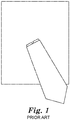
- Easel back picture or photo frames include a support structure attached to the back of the picture or photo frame that holds the frame upright.
- the easel back facilitates vertical display of the photo or picture frame, often at an angle of about 20° to the vertical.
- Easel back photo frame 100 includes frame portion 110 and easel back or easel stand portion 120.
- Easel back portion 120 is connected to frame portion 110 by a hinge 130.
- WO9931193 discloses a double sided, peel-able and stretchable adhesive tape for adhering objects to walls.
- easel backs or stands on picture or photo frames often prevent the picture or photo frame from being securely attached or adhered relatively flush to a wall using the attachment mechanisms provided on the frame (e.g. , keyhole, sawtooth).
- the easel back or easel stand portion has a thickness that can be greater than the thickness of the nail or attachment device.
- the easel backs or easel stands have a thickness that can make effective use of 3MTM COMMANDTM Picture Hanging Strips challenging. This is because the thickness of the easel back or easel stand can be similar to or greater than the thickness of the 3MTM COMMANDTM Picture Hanging Strip.
- a trend in home design is to hang various wall decorations overlapping with one another such that at least some of them are hung at varying distances from the wall or vertical surface.
- Two examples of such wall displays are provided in Figs. 2a and 2b .
- the inventors of the present disclosure invented improved picture hanging strip / mounting systems having an increased thickness.
- the picture hanging strips / mounting systems mount, hang, or affix objects (including, for example, easel back picture or photo frames) flush and/or adjacent to a wall or vertical surface without requiring removal of the easel stand or easel back.
- the picture hanging strips / mounting systems mount, hang, or affix objects (including, for example, easel back picture or photo frames) to a wall or vertical surface at a desired distance or depth from the wall or vertical surface.
- the user can select a third connector having a desired thickness to facilitate the depth at which the user desires the object to be spaced from the wall or vertical surface when hung, attached, or mounted.
- the mounting system embodiments described herein provide damage-free hanging.
- a mounting system comprising: (A) a first adhesive structure comprising: a first backing layer having first and second major surfaces and first and second ends;; a first adhesive surface over at least a portion of said first major surface of said first backing layer for bonding to a surface of an object; and a second adhesive surface over at least a portion of the second major surface of said first backing layer, the second adhesive surface bonded to a first separable connector layer, said second separable connector layer having a major surface covering at least a portion of said second major surface of said backing layer; (B) a second adhesive structure comprising: a second backing layer having first and second major surfaces and first and second ends; an adhesive surface over at least a portion of said first major surface of said second backing layer for bonding to a surface of another object; and a cooperating separable connector surface covering at least a portion of said second major surface of said second backing layer; wherein said cooperating separable connector surface possesses the ability to be connected, disconnected and reconnected to said connection surface of said
- At least one of the first and/or second adhesives are at least one of stretchable, peelable, or pressure sensitive. In some embodiments, at least one of the first or second backing layers are stretchable and/or stretch releasable.
- Some embodiments include a non-adhesive manually engageable tab portion at one of said first and second ends to facilitate removal of said first backing layer.
- the tab portion facilitates stretching of the first backing layer.
- said second backing layer and its adhesive surface are stretchable together to effect progressive debonding of the adhesive surface from the other object, after its adhesive surface is bonded to that object, by the application of a force to the first end of the second backing layer in a direction of extension of the second backing layer between its first and second ends.
- the third separable connector layer includes a loop-engaging portion on at least one of its two major surfaces.
- the third separable connector has a thickness that is between about 0.05 and about 1.0 inches. In some embodiments, the mounting system has a thickness that is between 0.15 inches and about 5 inches. In some embodiments, the mounting system has a thickness that is greater than the thickness of an easel back or stand on a picture or photo frame.
- the third separable connector is attached or adhered to one of the first or second adhesive structures.
- the separable connector system includes at least one of a mechanical type fastener or a loop-engaging fastener material.
- the separable connector system includes hook elements and loop elements, and at least some of the hooks elements have shape of at least one of a mushroom, a hook, a palm-tree, a nail, a T, or a J.
- the adhesive structures are separable so that the first separable connector layer remains with the first adhesive structure and the second separable connector layer remains with the second adhesive structure after separation.
- the third layer is a separable connector. In some embodiments, the third layer is a separate piece or unit. In some embodiments, the third layer is attached or adhered to one of the first or second adhesive structures.
- Some embodiments of the present disclosure constitute a mounting system comprising a picture hanging strip system having an increased thickness compared to a standard 3MTM COMMANDTM Picture Hanging Strip.
- the thickness is greater than the thickness of an article, such as, for example, an easel back or stand on a picture or photo frame.
- the thickness of the mounting system is at least 0.15 inches, 0.20 inches, 0.25 inches, 0.3 inches, 0.4 inches, 0.5 inches, 0.6 inches, 0.7 inches, 0.8 inches, 0.9 inches, 1.0 inch, 1.1 inch, 1.2 inch, 1.3 inch, 1.4 inch, 1.5 inch, 1.6 inch, 1.7 inch, 1.8 inch, 1.9 inch, 2.0 inches, 3 inches, 4 inches, or 5 inches.
- the thickness is between about 0.15 inch and 5 inches. In some embodiments, the thickness of the mounting system is less than 5 inches, less than 4 inches, less than 3 inches, less than 2 inches, less than 1 inch, less than 0.5 inch, less than 0.4 inch, and/or less than 0.3 inch.
- Picture hanging strips are described in, for example, U.S. Patent Nos. 6,692,807 and 6,572,945 .
- picture hanging strips refer to an adhesive tape construction that is removable from one or more objects to which it is adhered and which is reusably separable within its construction so that an object can be separated from another and subsequently reconnected with one another.
- the adhesive tape construction can be used to bond the other opposed surfaces of objects, including rigid objects such as a picture frame to a wall, where no portion of the adhesive tape construction projects from between the objects, and which subsequently affords easy separation of the objects without damage to either of them.
- the adhesive tape construction includes a stretch release adhesive tape structure combined with a reusable connector surface.
- the adhesive is at least one of peelable, and/or pressure sensitive.
- peelable adhesives include those described in, for example, PCT Patent Publication No. 2015/195344 .
- pressure sensitive refers to an adhesive that is configured to be in accordance with the Dahlquist criterion for pressure sensitive tack.
- the Dahlquist criterion is defined as an adhesive formulation that possesses a modulus of not more than 3 x 10 5 Pa at 25 °C at 1 Hz ( A.V.
- Picture hanging strip / adhesive tape construction 10 includes a first stretch release adhesive tape structure 12 and a second stretch release adhesive tape structure 14 connected together by two separable connector systems 16 and 100.
- the first stretch release adhesive structure 12 is connected with the second stretch release adhesive tape structure 14 by separable connector system 16 and with a first liner 18 covering one side of the adhesive tape 10 and a second liner 20 covering the other side of the adhesive tape 10.
- the first stretch release adhesive structure 12 comprises a backing layer 22 and adhesive layers 24 and 26 of the same or different pressure-sensitive adhesive compositions on opposite major surfaces of the backing layer 22.
- the thicknesses of the layers of the Figures are not to scale with respect to one another.
- second stretch release adhesive structure 14 likewise comprises a backing layer 28 and adhesive layers 30 and 32 of the same or different pressure-sensitive adhesive compositions on opposite major surfaces of the backing layer 28.
- the external surfaces of the adhesive layers 24 and 32 of the first and second stretch release adhesive tape structures 12 and 14, respectively, are covered by the liners 18 and 20, respectively.
- the thicknesses of one or more of the layers can be tailored for the end application. For example, the thickness of one or more of the layers can be increased to ensure that the total thickness of the mounting system is greater than the thickness of the easel back or stand.
- the backing layers 22 and 28, as illustrated, comprise a stretchable polymeric foam layer.
- the backing layers 22 and 28 can alternatively comprise a stretchable polymeric film layer.
- the choice of polymeric foam or polymeric film depends on the specific application for the adhesive tape 10.
- each of the first and second stretch release adhesive tape structures 12 and 14 preferably include a tab 34 and 36, respectively.
- tabs 34 and 36 facilitate the stretch release of each adhesive tape structure 12 and 14, respectively.
- Tab 34 is preferably provided as an extension of the backing layer 12. That is, the backing layer 22 extends farther longitudinally than the adhesive layers 24 or 26.
- Tab 36 comprises an extension of the backing layer 28 that extends farther longitudinally than the adhesive layers 30 and 32.
- the adhesive layers 24, 26, 30 and 32 each cover a similar area of the backing layers 22 and 28, respectively.
- tabs 34 and 36 can also be specifically shaped to facilitate the easy gripping thereof for the stretch release, described below.
- the tab(s) may further be desirable to make the tab(s) non-adhesive. This can be done by any way of masking the adhesive surface or by rendering the adhesive surface non-adhesive, i.e. detackifying the adhesive surface.
- separable connector system 16 preferably comprises a first connector component 38 and a second connector component 40.
- the first connector component 38 is bonded to the first stretch release adhesive tape structure 12 by the surface of adhesive layer 26.
- the second connector component 40 is bonded to the second stretch release adhesive tape structure 14 by the surface of adhesive layer 30.
- the first and second connector components 38 and 40 are preferably co-extensive with and cover the similar areas as the adhesive layers 24, 26, 30 and 32.
- the separable connector system 16 or 100 can comprise any known or developed reusable connector system for connecting the first and second stretch release adhesive tape structures 12 and 14 together.
- the separable connector system 16 permits the reusable separation and connection of the stretch release adhesive tape structures 12 and 14 along a general plane.
- the connector system 16 may comprise, for example, mechanical type fasteners, including interlocking systems, intermeshing systems (having connection without macroscopic mechanical deformation or interference), releasable contact responsive fasteners.
- the stretch release adhesive tape structures 12 and 14 are separable so that the first connector component 38 remains with the first stretch release adhesive tape structure 12 and the second connector component 40 remains with the second stretch release adhesive tape structure 14 after separation of the connector system 16.
- Separable connector system 100 can be any separable connector system, including, for example a loop-engaging fastener material.
- hook elements with loop-engaging heads have a head shape that is different from the shape of the stem.
- the term "loop-engaging” relates to the ability of a hook element to be mechanically attached to a loop material.
- the hook element may be in the shape of a mushroom (e.g., with a circular or oval head enlarged with respect to the stem), a hook, a palm-tree, a nail, a T, or a J.
- the loop-engageability of hook elements may be determined and defined by using standard woven, nonwoven, or knit materials.
- loop-engaging material is 3MTM Dual-LockTM fastener. Any loop-engaging material, apparatus, device, method of making, or method of use described in any of the following references can be used in any of the embodiments described herein: US Patent Nos.
- the area of connection and the type of the separable connector system 16 or 100 is preferably selected so that the force required to separate the adhesive tape 10 into the first and second stretch release adhesive tape structures 12 and 14 can be readily applied by a user.
- a force may be applied in a direction substantially perpendicular to the general plane of the connector system, or as a peeling force, a cleavage force, combinations thereof or other release mechanisms.
- the type of force applied depends largely on the objects that are bonded together. With very flexible materials, a peeling force would likely be a primary force utilized for releasing the separable connector system 16.
- a cleavage force may be mostly applied; that is where a person would pull from the bottom edge of the frame (causing angular displacement) to release the separable connector system 16 and/or 100 of the adhesive tape 10 located at the top. If the frame were pulled to release in a perpendicular direction, a perpendicular force is applied.
- the connector system 16 or 100 should provide sufficient strength along the general plane of its separation so that, depending on the specific application, the separable connector system 16 or 100 will not separate based on the use of the adhesive tape 10 between plural objects.
- the connector system 16 or 100 In the case of an object such as a picture frame mounted to a vertical wall surface, the connector system 16 or 100 should be of sufficient strength in the direction of its general plane of separation so that the picture frame will not shift downward during application or over time.
- the separable connector system 16 or 100 provides an internal static shear strength in a direction parallel to the surfaces of the adhesive layers 24 and 32 for supporting the objects between which the adhesive tape 10 is attached in that direction. That is, the shear strength of the connector system 16 or 100 preferably equals or exceeds the highest shear force that the pressure sensitive adhesive can develop with surfaces to which it is applied ( e.g. , about six pounds per square inch (0.041 MPa)).
- FIG. 5 shows a photographic front view of the mounting system shown in cross-section in Fig. 4 .
- Fig. 6A schematically shows mounting system 10.
- Fig. 6B schematically shows a prior art picture hanging strip in cross-section.
- adhesive tape 10 can be positioned between a first object 50 (a wall) and a second object 52 (a picture frame) without any portion of the adhesive tape 10 extending out from in between the first and second objects 50 and 52.
- the picture frame can be connected by a single adhesive tape 10 positioned to provide a balanced support to the wall; however, any number of adhesive tapes 10 can be used (for example, two mounting systems of the type described herein are used in Figs. 7 and 8 ).
- the ability to reposition the objects together is facilitated to allow for accurate alignment and balanced positioning.
- top, bottom, over, under in the description and the claims are used for descriptive purposes and not necessarily for describing relative positions. It is to be understood that the terms so used are interchangeable under appropriate circumstances and that the embodiments of the invention described herein are capable of operation in other orientations than described or illustrated herein.
Description
- The present disclosure generally relates to a mounting system capable of affixing an object to a wall or vertical surface.
- Easel back picture or photo frames include a support structure attached to the back of the picture or photo frame that holds the frame upright. When used with photo or picture frames, the easel back facilitates vertical display of the photo or picture frame, often at an angle of about 20° to the vertical.
- An exemplary schematic drawing of an easel back photo frame, viewed from the back, is shown in
Fig. 1 . Easelback photo frame 100 includes frame portion 110 and easel back or easel stand portion 120. Easel back portion 120 is connected to frame portion 110 by a hinge 130.WO9931193 - The inventors of the present disclosure recognized that easel backs or stands on picture or photo frames often prevent the picture or photo frame from being securely attached or adhered relatively flush to a wall using the attachment mechanisms provided on the frame (e.g., keyhole, sawtooth). This is because the easel back or easel stand portion has a thickness that can be greater than the thickness of the nail or attachment device. Additionally, the easel backs or easel stands have a thickness that can make effective use of 3M™ COMMAND™ Picture Hanging Strips challenging. This is because the thickness of the easel back or easel stand can be similar to or greater than the thickness of the 3M™ COMMAND™ Picture Hanging Strip. These issues can be resolved by removal of the easel back or easel stand, but removal of the easel stands or backs is challenging, time-consuming, and can impair or destroy the frame.
- Additionally, the inventors of the present disclosure recognized that a trend in home design is to hang various wall decorations overlapping with one another such that at least some of them are hung at varying distances from the wall or vertical surface. Two examples of such wall displays are provided in
Figs. 2a and 2b . - To address at least some of these problems, the inventors of the present disclosure invented improved picture hanging strip / mounting systems having an increased thickness. In some embodiments, the picture hanging strips / mounting systems mount, hang, or affix objects (including, for example, easel back picture or photo frames) flush and/or adjacent to a wall or vertical surface without requiring removal of the easel stand or easel back. In some embodiments, the picture hanging strips / mounting systems mount, hang, or affix objects (including, for example, easel back picture or photo frames) to a wall or vertical surface at a desired distance or depth from the wall or vertical surface. For example, in some embodiments, the user can select a third connector having a desired thickness to facilitate the depth at which the user desires the object to be spaced from the wall or vertical surface when hung, attached, or mounted. Further, the mounting system embodiments described herein provide damage-free hanging.
- Some embodiments relate to a mounting system, comprising: (A) a first adhesive structure comprising: a first backing layer having first and second major surfaces and first and second ends;; a first adhesive surface over at least a portion of said first major surface of said first backing layer for bonding to a surface of an object; and a second adhesive surface over at least a portion of the second major surface of said first backing layer, the second adhesive surface bonded to a first separable connector layer, said second separable connector layer having a major surface covering at least a portion of said second major surface of said backing layer; (B) a second adhesive structure comprising: a second backing layer having first and second major surfaces and first and second ends; an adhesive surface over at least a portion of said first major surface of said second backing layer for bonding to a surface of another object; and a cooperating separable connector surface covering at least a portion of said second major surface of said second backing layer; wherein said cooperating separable connector surface possesses the ability to be connected, disconnected and reconnected to said connection surface of said first backing layer without destruction of the separable connection surface, the cooperating connection surface and the adhesive tape; and (C) a third layer having opposing major surfaces that are capable of connecting to the first or second separable connector layers.
- In some embodiments, at least one of the first and/or second adhesives are at least one of stretchable, peelable, or pressure sensitive. In some embodiments, at least one of the first or second backing layers are stretchable and/or stretch releasable.
- Some embodiments include a non-adhesive manually engageable tab portion at one of said first and second ends to facilitate removal of said first backing layer. In some embodiments, the tab portion facilitates stretching of the first backing layer.
- In some embodiments, said second backing layer and its adhesive surface are stretchable together to effect progressive debonding of the adhesive surface from the other object, after its adhesive surface is bonded to that object, by the application of a force to the first end of the second backing layer in a direction of extension of the second backing layer between its first and second ends. In some embodiments, the third separable connector layer includes a loop-engaging portion on at least one of its two major surfaces.
- In some embodiments, the third separable connector has a thickness that is between about 0.05 and about 1.0 inches. In some embodiments, the mounting system has a thickness that is between 0.15 inches and about 5 inches. In some embodiments, the mounting system has a thickness that is greater than the thickness of an easel back or stand on a picture or photo frame.
- In some embodiments, the third separable connector is attached or adhered to one of the first or second adhesive structures.
- In some embodiments, the separable connector system includes at least one of a mechanical type fastener or a loop-engaging fastener material. In some embodiments, the separable connector system includes hook elements and loop elements, and at least some of the hooks elements have shape of at least one of a mushroom, a hook, a palm-tree, a nail, a T, or a J.
- In some embodiments, the adhesive structures are separable so that the first separable connector layer remains with the first adhesive structure and the second separable connector layer remains with the second adhesive structure after separation.
- In some embodiments, the third layer is a separable connector.In some embodiments, the third layer is a separate piece or unit. In some embodiments, the third layer is attached or adhered to one of the first or second adhesive structures.
-
-
Fig. 1 is a schematic drawing of a prior art easel-back picture frame viewed from the back. -
Figs. 2a and 2b are two schematic drawings of exemplary walls including various objects hung on the wall at varying depths to permit them to overlap. -
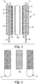
Fig. 3 is perspective view of an exemplary mounting system of the type generally described herein. -
Fig. 4 is a cross-sectional side view of an exemplary mounting system of the type generally described herein. -
Fig. 5 is a schematic drawing of a front view of the mounting system ofFig. 4 shown in cross-section. -
Fig. 6A is a schematic side view of an exemplary mounting system of the type described herein -
Fig. 6B is a schematic side view of a prior art picture hanging strip. -
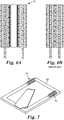
Fig. 7 is a schematic drawings of the back side of a picture or photo frame to which has been applied at least a portion of the mounting system generally described herein. -
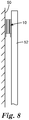
Fig. 8 is a schematic side view of a picture or photo frame attached and/or adhered to a wall using a mounting system of the general type described herein. - The figures are not necessarily to scale; some features may be exaggerated or minimized to show details of particular components. Therefore, specific structural and functional details disclosed herein are not to be interpreted as limiting, but merely as a representative basis for teaching one skilled in the art to variously employ the present invention.
- Some embodiments of the present disclosure constitute a mounting system comprising a picture hanging strip system having an increased thickness compared to a standard 3M™ COMMAND™ Picture Hanging Strip. In some embodiments, the thickness is greater than the thickness of an article, such as, for example, an easel back or stand on a picture or photo frame. In some embodiments, the thickness of the mounting system is at least 0.15 inches, 0.20 inches, 0.25 inches, 0.3 inches, 0.4 inches, 0.5 inches, 0.6 inches, 0.7 inches, 0.8 inches, 0.9 inches, 1.0 inch, 1.1 inch, 1.2 inch, 1.3 inch, 1.4 inch, 1.5 inch, 1.6 inch, 1.7 inch, 1.8 inch, 1.9 inch, 2.0 inches, 3 inches, 4 inches, or 5 inches. In some embodiments, the thickness is between about 0.15 inch and 5 inches. In some embodiments, the thickness of the mounting system is less than 5 inches, less than 4 inches, less than 3 inches, less than 2 inches, less than 1 inch, less than 0.5 inch, less than 0.4 inch, and/or less than 0.3 inch.
- Picture hanging strips are described in, for example,
U.S. Patent Nos. 6,692,807 and6,572,945 . In general, picture hanging strips, as used herein, refer to an adhesive tape construction that is removable from one or more objects to which it is adhered and which is reusably separable within its construction so that an object can be separated from another and subsequently reconnected with one another. The adhesive tape construction can be used to bond the other opposed surfaces of objects, including rigid objects such as a picture frame to a wall, where no portion of the adhesive tape construction projects from between the objects, and which subsequently affords easy separation of the objects without damage to either of them. - In some embodiments, the adhesive tape construction includes a stretch release adhesive tape structure combined with a reusable connector surface. In other embodiments, the adhesive is at least one of peelable, and/or pressure sensitive. Exemplary peelable adhesives include those described in, for example,
PCT Patent Publication No. 2015/195344 . As used herein, the term "pressure sensitive" refers to an adhesive that is configured to be in accordance with the Dahlquist criterion for pressure sensitive tack. The Dahlquist criterion is defined as an adhesive formulation that possesses a modulus of not more than 3 x 10⁵ Pa at 25 °C at 1 Hz (A.V. Pocius in "Adhesives and Adhesion Technology, 3rd Ed." 2012, Hanser Publications, Cincinnati, OH; also referenced inU.S, Patent Applications No. 2011/0179549 and inU.S. Patent Nos. 7,605,212 , and5,719,247 ). The Dahlquist criterion for pressure sensitive tack is also described as 1 sec compliance of a typical pressure-sensitive adhesive to be 10-6 cm2/dyne (D.A. Satas (ed.) in "Handbook of Pressure-Sensitive Adhesive Technology" 1982, Van Nostrand Reinhold Company Inc. New York, New York.). - An exemplary mounting system / picture hanging strip of the type generally described herein is shown schematically in
Figs. 3-4 . Picture hanging strip /adhesive tape construction 10 includes a first stretch releaseadhesive tape structure 12 and a second stretch releaseadhesive tape structure 14 connected together by twoseparable connector systems adhesive structure 12 is connected with the second stretch releaseadhesive tape structure 14 byseparable connector system 16 and with afirst liner 18 covering one side of theadhesive tape 10 and asecond liner 20 covering the other side of theadhesive tape 10. - In some embodiments, the first stretch release
adhesive structure 12 comprises abacking layer 22 andadhesive layers backing layer 22. The thicknesses of the layers of the Figures are not to scale with respect to one another. In some embodiments, second stretch releaseadhesive structure 14 likewise comprises abacking layer 28 andadhesive layers backing layer 28. In some embodiments, the external surfaces of theadhesive layers adhesive tape structures liners - In some embodiments, the backing layers 22 and 28, as illustrated, comprise a stretchable polymeric foam layer. In some embodiments, the backing layers 22 and 28 can alternatively comprise a stretchable polymeric film layer. The choice of polymeric foam or polymeric film depends on the specific application for the
adhesive tape 10. - In some embodiments, each of the first and second stretch release
adhesive tape structures tab tabs adhesive tape structure Tab 34 is preferably provided as an extension of thebacking layer 12. That is, thebacking layer 22 extends farther longitudinally than theadhesive layers Tab 36 comprises an extension of thebacking layer 28 that extends farther longitudinally than theadhesive layers adhesive layers tabs - In some embodiments,
separable connector system 16 preferably comprises afirst connector component 38 and asecond connector component 40. In some embodiments, thefirst connector component 38 is bonded to the first stretch releaseadhesive tape structure 12 by the surface ofadhesive layer 26. In some embodiments, thesecond connector component 40 is bonded to the second stretch releaseadhesive tape structure 14 by the surface ofadhesive layer 30. In some embodiments, the first andsecond connector components adhesive layers - In some embodiments, the
separable connector system adhesive tape structures separable connector system 16 permits the reusable separation and connection of the stretch releaseadhesive tape structures connector system 16 may comprise, for example, mechanical type fasteners, including interlocking systems, intermeshing systems (having connection without macroscopic mechanical deformation or interference), releasable contact responsive fasteners. In some embodiments, the stretch releaseadhesive tape structures first connector component 38 remains with the first stretch releaseadhesive tape structure 12 and thesecond connector component 40 remains with the second stretch releaseadhesive tape structure 14 after separation of theconnector system 16. -
Separable connector system 100 can be any separable connector system, including, for example a loop-engaging fastener material. Generally, hook elements with loop-engaging heads have a head shape that is different from the shape of the stem. As used herein, the term "loop-engaging" relates to the ability of a hook element to be mechanically attached to a loop material. For example, the hook element may be in the shape of a mushroom (e.g., with a circular or oval head enlarged with respect to the stem), a hook, a palm-tree, a nail, a T, or a J. The loop-engageability of hook elements may be determined and defined by using standard woven, nonwoven, or knit materials. One exemplary commercially available loop-engaging material is 3M™ Dual-Lock™ fastener. Any loop-engaging material, apparatus, device, method of making, or method of use described in any of the following references can be used in any of the embodiments described herein:US Patent Nos. 8,777,919 ;4,699,622 ;4,894,060 ;5,077,870 ;5,312,387 ;5,344,691 ;5,399,219 ;5,487,809 ;5,537,722 ;5,554,146 ;5,705,013 ;5,759,317 ;5,851,205 ;5,957,908 ;5,985,081 ;6,030,373 ;6,051,094 ;6,075,179 ;6,190,758 ;6,406,468 ;6,544,245 ;6,575,953 ;7,032,278 ;7,125,400 ;7,361,246 ;7,371,302 ;7,517,572 ;7,578,812 ;7,658,813 ;3,471,903 ;4,120,718 ;4,223,067 ;4,216,257 ;4,391,687 ;4,322,875 ;4,415,615 ;4,454,183 ;4,563,388 ;3,353,663 ;3,408,705 ;4,977,003 ;4,679,851 ;4,819,309 ;4,776,636 ;5,308,428 ;5,135,598 ;4,910,062 ;4,887,339 ;4,985,488 ;5,679,302 ;4,894,060 ;5,145,929 ;5,908,695 ;5,024,880 ;5,852,855 ;5,040,275 ;5,149,573 ;4,290,832 ;5,453,319 ;5,614,232 ;5,691,027 ;5,713,111 ;5,671,512 ;5,625,929 ;5,671,511 ;5,851,663 ;5,654,487 ;5,602,221 ;5,598,610 ;5,691,021 ;7,879,441 ;8,277,922 ;6,470,540 ;6,076,238 ;6,592,800 ;6,630,239 ;6,588,074 ;7,217,455 ;7,703,179 ;6,874,777 ;7,140,774 ; andUS Patent Publication No. 2004/0010217 . - In some embodiments, the area of connection and the type of the
separable connector system adhesive tape 10 into the first and second stretch releaseadhesive tape structures separable connector system 16. With rigid materials, a cleavage force may be mostly applied; that is where a person would pull from the bottom edge of the frame (causing angular displacement) to release theseparable connector system 16 and/or 100 of theadhesive tape 10 located at the top. If the frame were pulled to release in a perpendicular direction, a perpendicular force is applied. Moreover, theconnector system separable connector system adhesive tape 10 between plural objects. In the case of an object such as a picture frame mounted to a vertical wall surface, theconnector system separable connector system adhesive layers adhesive tape 10 is attached in that direction. That is, the shear strength of theconnector system -
Fig. 5 shows a photographic front view of the mounting system shown in cross-section inFig. 4 .Fig. 6A schematically shows mountingsystem 10.Fig. 6B schematically shows a prior art picture hanging strip in cross-section. - As shown schematically in
Figs. 7 and8 ,adhesive tape 10 can be positioned between a first object 50 (a wall) and a second object 52 (a picture frame) without any portion of theadhesive tape 10 extending out from in between the first andsecond objects adhesive tape 10 positioned to provide a balanced support to the wall; however, any number ofadhesive tapes 10 can be used (for example, two mounting systems of the type described herein are used inFigs. 7 and8 ). Moreover, the ability to reposition the objects together is facilitated to allow for accurate alignment and balanced positioning. - The recitation of all numerical ranges by endpoint is meant to include all numbers subsumed within the range (i.e., the range 1 to 10 includes, for example, 1, 1.5, 3.33, and 10).
- The terms first, second, third in the description and in the claims, are used for distinguishing between similar elements and not necessarily for describing a sequential or chronological order. It is to be understood that the terms so used are interchangeable under appropriate circumstances and that the embodiments of the invention described herein are capable of operation in other sequences than described or illustrated herein.
- Moreover, the terms top, bottom, over, under in the description and the claims are used for descriptive purposes and not necessarily for describing relative positions. It is to be understood that the terms so used are interchangeable under appropriate circumstances and that the embodiments of the invention described herein are capable of operation in other orientations than described or illustrated herein.
Claims (14)
- A mounting system, comprising:
a first adhesive structure (12) comprising:a first backing layer (22) having first and second major surfaces and first and second ends;a first adhesive layer (24) over at least a portion of said first major surface of said first backing layer (22) for bonding to a surface of an object and a second adhesive layer (26) over at least a portion of the second major surface;wherein the second major surface of said first backing layer (22) is bonded to a first separable connector component (38) via the second adhesive layer (26),said first separable connector component (38) having a major surface covering at least a portion of said second major surface of said first backing layer (22) and having a first separable connector surface;a second adhesive structure (14) comprising:a second backing layer (28) having first and second major surfaces and first and second ends;a first adhesive layer (32) over at least a portion of said first major surface of said second backing layer (28) for bonding to a surface of another object and a second adhesive layer (30) over at least a portion of the second major surface; anda second separable connector component (40) having a second separable connector surface covering at least a portion of said second major surface of said second backing layer (28); anda third layer (100) having opposing major surfaces that are capable of connecting to the first separable connector component (38)and the second separable connector component(40), wherein, when the system is assembled, the third layer (100) is disposed between the first and second adhesive structures (12, 14). - The mounting system of claim 1, wherein the third layer (100) includes a loop-engaging portion on at least one of its two major surfaces.
- The mounting system of any of the preceding claims, wherein the third layer (100) has a thickness that is between 0.127cm and 2.54cm.
- The mounting system of any of the preceding claims, wherein the mounting system, has a thickness that is between 0.381cm and 12.7cm.
- The mounting system of any of the preceding claims, wherein the mounting system, has a thickness that is greater than the thickness of an easel back or stand on a picture or photo frame.
- The mounting system of any of the preceding claims, wherein at least one of the first and second adhesive structures (12, 14) is stretch-releasable.
- The mounting system of claim 1 or 6, wherein said second backing layer (28) of the second adhesive structure (14) and its adhesive layers (30, 32) are stretchable together to effect progressive debonding of the adhesive surface from a second object, after its adhesive surface is bonded to that second object, by the application of a force to the first end of the second backing layer (28) in a direction of extension of the second backing layer (28) between its first and second ends.
- The mounting system of any of the preceding claims, further including:
a non-adhesive manually engageable tab portion (34, 36) at one of said first and second ends to facilitate removal of said first backing layer. - The mounting system of any of the preceding claims , wherein at least one of the first adhesive layers (24, 32) on either the first adhesive structure (12) or second adhesive structure (14) includes a pressure sensitive adhesive.
- The mounting system of any of the preceding claims, whereini) the first separable connector component (38) of the first adhesive structure (12) and the third layer (100) define a first separable connector system, whereinii) the second separable connector component (40) of the second adhesive structure (14) and the third layer (100) define a second separable connector system, andwherein each of the first and second separable connector systems includes at least one of a mechanical type fastener or a loop-engaging fastener material.
- The mounting system of claim 10, wherein the at least one of the first and second separable connector systems includes hook elements and loop elements, and at least some of the hooks elements have shape of at least one of a mushroom, a hook, a palm-tree, a nail, a T, or a J.
- The mounting system of any of the preceding claims, wherein the adhesive structures are separable from the third layer (100) so that the first separable connector component (38) remains with the first adhesive structure (12) and the second separable connector component (40) remains with the second adhesive structure (14) after separation.
- The mounting system of any of the preceding claims, wherein the third layer includes loop-engaging portions..
- The mounting system of any of the preceding claims, wherein said second separable connector component (40) possesses the ability to be connected, disconnected and reconnected to said third layer (100) without destruction of at least one of;a) the second separable connection component(40), andb) the first and second adhesive layers (30, 32) on the second backing layer (28), andwherein said first separable connector component (38) possesses the ability to be connected, disconnected and reconnected to said third layer (100) without destruction of at least one of;a) the first separable connection component (38), andb) the first and second adhesive layers (24, 26) on the first backing layer (22).
Applications Claiming Priority (3)
| Application Number | Priority Date | Filing Date | Title |
|---|---|---|---|
| US201562134722P | 2015-03-18 | 2015-03-18 | |
| US201562213765P | 2015-09-03 | 2015-09-03 | |
| PCT/US2016/021469 WO2016148992A1 (en) | 2015-03-18 | 2016-03-09 | Mounting system |
Publications (3)
| Publication Number | Publication Date |
|---|---|
| EP3271167A1 EP3271167A1 (en) | 2018-01-24 |
| EP3271167A4 EP3271167A4 (en) | 2018-10-10 |
| EP3271167B1 true EP3271167B1 (en) | 2021-08-18 |
Family
ID=56920425
Family Applications (1)
| Application Number | Title | Priority Date | Filing Date |
|---|---|---|---|
| EP16765439.1A Active EP3271167B1 (en) | 2015-03-18 | 2016-03-09 | Mounting system |
Country Status (7)
| Country | Link |
|---|---|
| US (1) | US10259194B2 (en) |
| EP (1) | EP3271167B1 (en) |
| JP (1) | JP6895385B2 (en) |
| KR (1) | KR20170129166A (en) |
| CN (1) | CN107428119B (en) |
| TW (1) | TWI716388B (en) |
| WO (1) | WO2016148992A1 (en) |
Families Citing this family (5)
| Publication number | Priority date | Publication date | Assignee | Title |
|---|---|---|---|---|
| US10575664B2 (en) * | 2015-07-16 | 2020-03-03 | Oribel Pte. Ltd. | Article for mounting to a vertical surface |
| US10624474B2 (en) * | 2017-05-06 | 2020-04-21 | Leonid Taratuta | Wall mounting apparatus and methods |
| US10786097B2 (en) * | 2017-08-30 | 2020-09-29 | Bjorn Austraat | Wall hanging device |
| US20200000229A1 (en) * | 2018-06-28 | 2020-01-02 | Summit Product Development, LLC | Low Profile Cabinet Organizer |
| US10550580B1 (en) * | 2018-08-02 | 2020-02-04 | Velcro BVBA | Acoustic panel wall mounting |
Family Cites Families (103)
| Publication number | Priority date | Publication date | Assignee | Title |
|---|---|---|---|---|
| US3353663A (en) | 1966-02-10 | 1967-11-21 | Minnesota Mining & Mfg | Adherent fasteners |
| US3408705A (en) | 1966-07-07 | 1968-11-05 | Minnesota Mining & Mfg | Fastener articles |
| US3471903A (en) | 1967-10-24 | 1969-10-14 | Minnesota Mining & Mfg | Stud-backed fasteners |
| US4019948A (en) | 1975-09-22 | 1977-04-26 | Minnesota Mining And Manufacturing Company | Applicator for heat-activatable tape |
| US4290832A (en) | 1976-08-13 | 1981-09-22 | Minnesota Mining And Manufacturing Company | Method for making fasteners |
| US4223067A (en) | 1978-03-27 | 1980-09-16 | Minnesota Mining And Manufacturing Company | Foam-like pressure-sensitive adhesive tape |
| US4216257A (en) | 1979-04-20 | 1980-08-05 | Minnesota Mining And Manufacturing Company | Strip material for forming flexible backed fasteners |
| US4391687A (en) | 1980-02-14 | 1983-07-05 | Minnesota Mining And Manufacturing Company | Photoactive mixture of acrylic monomers and chromophore-substituted halomethyl-1-triazine |
| US4322875A (en) | 1980-03-31 | 1982-04-06 | Minnesota Mining And Manfacturing Company | Two strip materials used for forming fasteners |
| US4310137A (en) * | 1980-09-08 | 1982-01-12 | Frye Bruce J | Self holding separable mount |
| US4415615A (en) | 1982-01-15 | 1983-11-15 | Minnesota Mining And Manufacturing Co. | Cellular pressure-sensitive adhesive product and method of making |
| US4454183A (en) | 1982-02-26 | 1984-06-12 | Minnesota Mining And Manufacturing Company | Strip material with heat-formed hooked heads |
| US4563388A (en) | 1983-03-28 | 1986-01-07 | Minnesota Mining And Manufacturing Company | Polyolefin substrate coated with acrylic-type normally tacky and pressure-sensitive adhesive and a method of making same |
| US4977003A (en) | 1985-02-20 | 1990-12-11 | Minnesota Mining And Manufacturing Company | Nontacky acrylonitrile/butadiene adhesive tape |
| US4679851A (en) | 1985-07-31 | 1987-07-14 | Minnesota Mining And Manufacturing Company | Cushion and method |
| US4699622A (en) | 1986-03-21 | 1987-10-13 | The Procter & Gamble Company | Disposable diaper having an improved side closure |
| US5132172A (en) | 1986-06-11 | 1992-07-21 | Minnesota Mining And Manufacturing Company | Primed polyolefin surfaces for epoxy adhesives |
| US4776636A (en) | 1986-10-31 | 1988-10-11 | Minnesota Mining And Manufacturing Company | Button forming assembly |
| US5135598A (en) | 1987-08-13 | 1992-08-04 | Minnesota Mining And Manufacturing Company | Priming polymeric surfaces for cyanoacrylate adhesives |
| US4819309A (en) | 1987-08-27 | 1989-04-11 | Minnesota Mining And Manufacturing Company | Fastener with parts having projecting engaging portions |
| US4894060A (en) | 1988-01-11 | 1990-01-16 | Minnesota Mining And Manufacturing Company | Disposable diaper with improved hook fastener portion |
| IE890122L (en) | 1988-02-23 | 1989-08-23 | Minnesota Mining & Mfg | Sheet material used to form portions of fasteners |
| US4985488A (en) | 1988-05-20 | 1991-01-15 | Minnesota Mining And Manufacturing Company | Pressure-sensitive adhesive having improved adhesion to plasticized vinyl substrates |
| US4887339A (en) | 1988-07-18 | 1989-12-19 | Minnesota Mining And Manufacturing Company | Strip material with tab-like parts for forming fasteners |
| US6406468B1 (en) | 1988-12-20 | 2002-06-18 | Kimberly-Clark Worldwide, Inc. | Mechanical fastening tapes and method for their construction |
| US5145929A (en) | 1989-02-01 | 1992-09-08 | Minnesota Mining And Manufacturing Company | Pressure-activated adhesives |
| US6205685B1 (en) * | 1989-09-14 | 2001-03-27 | Kellerman Company Llc | Adjustable orthotic |
| US4942071A (en) * | 1989-10-23 | 1990-07-17 | Frye Bruce J | Adhesive holding device with separable elements |
| US5888335A (en) | 1989-10-26 | 1999-03-30 | Minnesota Mining And Manufacturing Company | Multiple releasable contact responsive fasteners |
| US5852855A (en) | 1989-11-17 | 1998-12-29 | Minnesota Mining And Manufacturing Company | Disposable diaper with fastener |
| US5024880A (en) | 1990-01-03 | 1991-06-18 | Minnesota Mining And Manufacturing Company | Cellular pressure-sensitive adhesive membrane |
| US5344691A (en) | 1990-03-30 | 1994-09-06 | Minnesota Mining And Manufacturing Company | Spatially modified elastic laminates |
| US5149573A (en) | 1990-06-01 | 1992-09-22 | Minnesota Mining And Manufacturing Company | Highly transparent strip material used for forming fasteners |
| US5040275A (en) | 1990-06-01 | 1991-08-20 | Minnesota Mining And Manufacturing Company | Strip material used for forming fasteners |
| US5679302A (en) | 1990-09-21 | 1997-10-21 | Minnesota Mining And Manufacturing Company | Method for making a mushroom-type hook strip for a mechanical fastener |
| US5077870A (en) | 1990-09-21 | 1992-01-07 | Minnesota Mining And Manufacturing Company | Mushroom-type hook strip for a mechanical fastener |
| US5719247A (en) | 1991-12-17 | 1998-02-17 | Minnesota Mining And Manufacturing Company | Tack-free elastomeric acrylate microspheres |
| US5242646A (en) | 1992-05-07 | 1993-09-07 | Minnesota Mining And Manufacturing Company | Method of making an interengaging fastener member |
| US5342685A (en) | 1992-05-18 | 1994-08-30 | Minnesota Mining And Manufacturing Company | Hot-melt-coatable adhesives |
| US5312387A (en) | 1993-02-11 | 1994-05-17 | Minnesota Mining And Manufacturing Company | Rounded corner fastening tab diaper closure |
| ES2131636T3 (en) | 1993-04-06 | 1999-08-01 | Bp Chem Int Ltd | CATALYTIC COMPOSITION. |
| ES2166855T3 (en) * | 1993-04-16 | 2002-05-01 | Minnesota Mining & Mfg | ASSEMBLY OF STORAGE / DISPENSATION OF A BROOCH MATERIAL WITH LOOP. |
| US5691027A (en) | 1993-07-27 | 1997-11-25 | Minnesota Mining And Manufacturing Company | Fastener with a dual purpose cover sheet |
| JP3889452B2 (en) | 1993-07-30 | 2007-03-07 | スリーエム カンパニー | Face-to-face engagement fastener member |
| JP3476867B2 (en) | 1993-08-05 | 2003-12-10 | ミネソタ マイニング アンド マニュファクチャリング カンパニー | Face-to-face engagement fastener member |
| JPH0779810A (en) | 1993-08-25 | 1995-03-28 | Minnesota Mining & Mfg Co <3M> | Opposite interlocking zipper member and production thereof |
| US5602221A (en) | 1993-11-10 | 1997-02-11 | Minnesota Mining And Manufacturing Company | Pressure sensitive adhesives with good low energy surface adhesion |
| US5399219A (en) | 1994-02-23 | 1995-03-21 | Kimberly-Clark Corporation | Method for making a fastening system for a dynamic fitting diaper |
| JPH07275014A (en) | 1994-04-01 | 1995-10-24 | Minnesota Mining & Mfg Co <3M> | Face-toface engaging fastener member and its manufacture, and affixing member equipped with face-to-face engaging fastener |
| US5554146A (en) | 1994-05-06 | 1996-09-10 | Minnesota Mining And Manufacturing Company | Mechanical fastener for disposable article |
| US5851663A (en) | 1994-05-25 | 1998-12-22 | Minnesota Mining And Manufacturing Company | Flame retardant pressure-sensitive adhesives and tapes |
| US5487809A (en) | 1994-06-21 | 1996-01-30 | The Procter & Gamble Company | Method for manufacturing tape tab stock that may be used to produce tape tab fasteners for disposable absorbent articles |
| US5713111A (en) | 1994-07-27 | 1998-02-03 | Minnesota Mining And Manufacturing Company | Method for making an interengaging fastener having reduced engagement force |
| ZA9510604B (en) | 1994-12-20 | 1996-07-03 | Kimberly Clark Co | Low gauge films and film/nonwoven laminates |
| US5705013A (en) | 1995-02-10 | 1998-01-06 | The Procter & Gamble Company | Method for manufacturing extensible side panels for absorbent articles |
| US6030373A (en) | 1995-04-13 | 2000-02-29 | Kimberly-Clark Worldwide, Inc. | Multi-attachment fastening system |
| MX9708465A (en) | 1995-05-02 | 1998-02-28 | Kimberly Clark Co | Nonwoven-film laminates. |
| JP3167889B2 (en) | 1995-07-28 | 2001-05-21 | ユニ・チャーム株式会社 | Disposable diapers |
| US5691021A (en) | 1996-02-28 | 1997-11-25 | Minnesota Mining And Manufacturing Company | Flame retardant fastener and method for making the same |
| US5897545A (en) | 1996-04-02 | 1999-04-27 | The Procter & Gamble Company | Elastomeric side panel for use with convertible absorbent articles |
| US5759317A (en) | 1996-07-22 | 1998-06-02 | Kimberly-Clark Worldwide, Inc. | Process for making a mechanical fastener |
| ES2205321T3 (en) * | 1997-06-21 | 2004-05-01 | Tesa Ag | COMPOSED BASED ON ADHESIVE STRIPS AND ITS USE. |
| US6051094A (en) | 1997-10-06 | 2000-04-18 | 3M Innovative Properties Company | Closure system for disposable absorbent article |
| US6972141B1 (en) * | 1997-12-12 | 2005-12-06 | 3M Innovative Properties Company | Removable adhesive tape laminate and separable fastener |
| US6120867A (en) | 1998-01-27 | 2000-09-19 | 3M Innovative Properties Company | Removable tape laminate |
| US5985081A (en) | 1998-06-26 | 1999-11-16 | Kimberly-Clark Worldwide, Inc. | Process for making a shaped product with no material waste |
| US6103152A (en) | 1998-07-31 | 2000-08-15 | 3M Innovative Properties Co. | Articles that include a polymer foam and method for preparing same |
| US8277922B2 (en) | 1998-10-05 | 2012-10-02 | 3M Innovative Properties Company | Stem web |
| AU2057100A (en) | 1998-12-18 | 2000-07-03 | Kimberly-Clark Worldwide, Inc. | Absorbent articles having hinged fasteners |
| US6076238A (en) | 1999-04-13 | 2000-06-20 | 3M Innovative Properties Company | Mechanical fastener |
| US6303062B1 (en) | 1999-04-13 | 2001-10-16 | 3M Innovative Properties Company | Mechanical fastener and method for making the same |
| US6592800B1 (en) | 1999-10-04 | 2003-07-15 | 3M Innovative Properties Company | Apparatus and method for making a mechanical fastener |
| US6379791B1 (en) | 2000-02-08 | 2002-04-30 | 3M Innovative Properties Company | Compatibilized pressure-sensitive adhesives |
| US6546604B2 (en) | 2000-02-10 | 2003-04-15 | 3M Innovative Properties Company | Self-mating reclosable mechanical fastener and binding strap |
| US7578812B2 (en) | 2001-03-01 | 2009-08-25 | Kimberly-Clark Worldwide, Inc. | Pre-fastened absorbent article having simplified fastening features |
| US6544245B2 (en) | 2001-05-10 | 2003-04-08 | Velcro Industries B.V. | Bi-stable fastening |
| US7217455B2 (en) | 2001-05-30 | 2007-05-15 | 3M Innovative Properties Company | Weatherstrip tape and method for producing the same |
| US7703179B2 (en) | 2001-11-09 | 2010-04-27 | 3M Innovative Properties Company | Microreplicated surface |
| US6663063B2 (en) * | 2002-03-18 | 2003-12-16 | Andrew Tatta | Device and method for supporting an electronic toll pass assembly against the windshield of a vehicle |
| JP2003300636A (en) | 2002-04-08 | 2003-10-21 | Three M Innovative Properties Co | Sheet feeder, sheet separating member, sheet feeding assembly and sheet separating assembly |
| US20040010217A1 (en) | 2002-07-15 | 2004-01-15 | Blette Russell E. | Friction enhancing apparatus and method of application thereof |
| US7371302B2 (en) | 2002-07-23 | 2008-05-13 | The Procter & Gamble Company | Method for forming fastening members |
| US20040170342A1 (en) | 2003-02-28 | 2004-09-02 | 3M Innovative Properties Company | Slidable fastener bearing assembly |
| US7658813B2 (en) | 2003-02-28 | 2010-02-09 | 3M Innovative Properties Company | Method of preparing closure components suitable for use in diapers |
| US7032278B2 (en) | 2003-03-03 | 2006-04-25 | Velcro Industries B.V. | Hook fastener engaging zones |
| JP3652691B2 (en) | 2003-05-23 | 2005-05-25 | ユニ・チャーム株式会社 | Open disposable diaper |
| US20050006552A1 (en) * | 2003-07-11 | 2005-01-13 | Edward Giles | Soft pad picture mount |
| US7361246B2 (en) | 2003-12-24 | 2008-04-22 | Dsg Technology Holdings Ltd. | Elastic composite for a disposable absorbent garment, and a system and process for making the elastic composite and a garment having the elastic composite |
| CN2693045Y (en) * | 2004-05-13 | 2005-04-20 | 蔡瑞斌 | Double face adhesive of traceless hook |
| ES2341117T3 (en) | 2004-09-09 | 2010-06-15 | Tesa Se | METHOD FOR PREPARING ACRYLIC SELF-ADHESIVE MASSES. |
| US7517572B2 (en) | 2005-04-27 | 2009-04-14 | Kimberly-Clark Worldwide, Inc. | Composite web |
| DE602006001713D1 (en) * | 2005-05-05 | 2008-08-21 | Velcro Ind | FORMS OF CONNECTING SHARES ON SUBSTRATES |
| TWM299527U (en) * | 2006-04-18 | 2006-10-21 | King Polar Bear Co Ltd | Hanging hook |
| US7594636B2 (en) * | 2006-06-27 | 2009-09-29 | Hammond Wong | Picture frame positioner |
| EP2262868B1 (en) * | 2008-03-14 | 2018-02-28 | 3M Innovative Properties Company | Stretch releasable adhesive tape |
| DE102008044982B4 (en) | 2008-08-29 | 2012-12-06 | W. L. Gore & Associates Gmbh | Layer structure with a barrier layer, garment with such a layer structure and method for producing such a layer structure |
| EP2379666B1 (en) * | 2008-12-31 | 2016-03-23 | 3M Innovative Properties Company | Adhesive tape and articles comprising stretch releasable pressure-sensitive adhesive |
| US8572907B2 (en) * | 2009-02-19 | 2013-11-05 | Saint-Gobain Performance Plastics Corporation | Attachment system of photovoltaic cell to fluoropolymer structural membrane |
| US8814124B1 (en) * | 2010-02-23 | 2014-08-26 | Vladimir Vayntraub | Article hanging device |
| US8777919B2 (en) | 2010-12-07 | 2014-07-15 | 3M Innovative Properties Company | Fastening tab and method of making the same |
| US8430371B2 (en) * | 2011-09-02 | 2013-04-30 | Steven G. Boelstler | Quick release hook and loop device |
| EP3054816B1 (en) | 2014-06-17 | 2020-05-27 | 3M Innovative Properties Company | Article support using peel release adhesives |
| JP3194035U (en) * | 2014-08-21 | 2014-10-30 | Ykk株式会社 | Wall fasteners |
-
2016
- 2016-03-09 KR KR1020177027286A patent/KR20170129166A/en not_active Application Discontinuation
- 2016-03-09 EP EP16765439.1A patent/EP3271167B1/en active Active
- 2016-03-09 US US15/559,154 patent/US10259194B2/en active Active
- 2016-03-09 WO PCT/US2016/021469 patent/WO2016148992A1/en active Application Filing
- 2016-03-09 JP JP2017548275A patent/JP6895385B2/en active Active
- 2016-03-09 CN CN201680016259.2A patent/CN107428119B/en active Active
- 2016-03-17 TW TW105108337A patent/TWI716388B/en active
Non-Patent Citations (1)
| Title |
|---|
| None * |
Also Published As
| Publication number | Publication date |
|---|---|
| WO2016148992A1 (en) | 2016-09-22 |
| US10259194B2 (en) | 2019-04-16 |
| EP3271167A4 (en) | 2018-10-10 |
| TW201641063A (en) | 2016-12-01 |
| EP3271167A1 (en) | 2018-01-24 |
| TWI716388B (en) | 2021-01-21 |
| US20180065338A1 (en) | 2018-03-08 |
| CN107428119B (en) | 2020-05-15 |
| JP2018512203A (en) | 2018-05-17 |
| CN107428119A (en) | 2017-12-01 |
| JP6895385B2 (en) | 2021-06-30 |
| KR20170129166A (en) | 2017-11-24 |
Similar Documents
| Publication | Publication Date | Title |
|---|---|---|
| EP3271167B1 (en) | Mounting system | |
| TWI672112B (en) | Article support using peel release adhesives | |
| US6572945B2 (en) | Removable adhesive tape laminate and separable fastener | |
| US11819146B2 (en) | Flexible hardgoods with enhanced peel removability | |
| US8430371B2 (en) | Quick release hook and loop device | |
| EP3273826B1 (en) | Canvas mounting device | |
| CN107635445B (en) | Improved mounting assembly | |
| WO2023163717A1 (en) | Flexible adhesive mounting articles including intermittently connected body segments | |
| TW202031837A (en) | Flexible adhesive mounting articles including intermittently connected body segments |
Legal Events
| Date | Code | Title | Description |
|---|---|---|---|
| STAA | Information on the status of an ep patent application or granted ep patent |
Free format text: STATUS: THE INTERNATIONAL PUBLICATION HAS BEEN MADE |
|
| PUAI | Public reference made under article 153(3) epc to a published international application that has entered the european phase |
Free format text: ORIGINAL CODE: 0009012 |
|
| STAA | Information on the status of an ep patent application or granted ep patent |
Free format text: STATUS: REQUEST FOR EXAMINATION WAS MADE |
|
| 17P | Request for examination filed |
Effective date: 20170914 |
|
| AK | Designated contracting states |
Kind code of ref document: A1 Designated state(s): AL AT BE BG CH CY CZ DE DK EE ES FI FR GB GR HR HU IE IS IT LI LT LU LV MC MK MT NL NO PL PT RO RS SE SI SK SM TR |
|
| AX | Request for extension of the european patent |
Extension state: BA ME |
|
| DAV | Request for validation of the european patent (deleted) | ||
| DAX | Request for extension of the european patent (deleted) | ||
| A4 | Supplementary search report drawn up and despatched |
Effective date: 20180906 |
|
| RIC1 | Information provided on ipc code assigned before grant |
Ipc: C09J 7/00 20180101ALI20180901BHEP Ipc: B32B 7/06 20060101AFI20180901BHEP Ipc: B32B 7/04 20060101ALI20180901BHEP Ipc: B32B 7/08 20060101ALI20180901BHEP |
|
| RIC1 | Information provided on ipc code assigned before grant |
Ipc: C09J 7/00 20180101ALI20201125BHEP Ipc: B32B 7/04 20190101ALI20201125BHEP Ipc: B32B 7/08 20190101ALI20201125BHEP Ipc: B32B 7/06 20190101AFI20201125BHEP |
|
| GRAP | Despatch of communication of intention to grant a patent |
Free format text: ORIGINAL CODE: EPIDOSNIGR1 |
|
| STAA | Information on the status of an ep patent application or granted ep patent |
Free format text: STATUS: GRANT OF PATENT IS INTENDED |
|
| INTG | Intention to grant announced |
Effective date: 20210225 |
|
| GRAS | Grant fee paid |
Free format text: ORIGINAL CODE: EPIDOSNIGR3 |
|
| GRAA | (expected) grant |
Free format text: ORIGINAL CODE: 0009210 |
|
| STAA | Information on the status of an ep patent application or granted ep patent |
Free format text: STATUS: THE PATENT HAS BEEN GRANTED |
|
| AK | Designated contracting states |
Kind code of ref document: B1 Designated state(s): AL AT BE BG CH CY CZ DE DK EE ES FI FR GB GR HR HU IE IS IT LI LT LU LV MC MK MT NL NO PL PT RO RS SE SI SK SM TR |
|
| REG | Reference to a national code |
Ref country code: GB Ref legal event code: FG4D |
|
| REG | Reference to a national code |
Ref country code: CH Ref legal event code: EP |
|
| REG | Reference to a national code |
Ref country code: DE Ref legal event code: R096 Ref document number: 602016062403 Country of ref document: DE |
|
| REG | Reference to a national code |
Ref country code: IE Ref legal event code: FG4D Ref country code: AT Ref legal event code: REF Ref document number: 1421270 Country of ref document: AT Kind code of ref document: T Effective date: 20210915 |
|
| REG | Reference to a national code |
Ref country code: LT Ref legal event code: MG9D |
|
| REG | Reference to a national code |
Ref country code: NL Ref legal event code: MP Effective date: 20210818 |
|
| REG | Reference to a national code |
Ref country code: AT Ref legal event code: MK05 Ref document number: 1421270 Country of ref document: AT Kind code of ref document: T Effective date: 20210818 |
|
| PG25 | Lapsed in a contracting state [announced via postgrant information from national office to epo] |
Ref country code: ES Free format text: LAPSE BECAUSE OF FAILURE TO SUBMIT A TRANSLATION OF THE DESCRIPTION OR TO PAY THE FEE WITHIN THE PRESCRIBED TIME-LIMIT Effective date: 20210818 Ref country code: FI Free format text: LAPSE BECAUSE OF FAILURE TO SUBMIT A TRANSLATION OF THE DESCRIPTION OR TO PAY THE FEE WITHIN THE PRESCRIBED TIME-LIMIT Effective date: 20210818 Ref country code: HR Free format text: LAPSE BECAUSE OF FAILURE TO SUBMIT A TRANSLATION OF THE DESCRIPTION OR TO PAY THE FEE WITHIN THE PRESCRIBED TIME-LIMIT Effective date: 20210818 Ref country code: NO Free format text: LAPSE BECAUSE OF FAILURE TO SUBMIT A TRANSLATION OF THE DESCRIPTION OR TO PAY THE FEE WITHIN THE PRESCRIBED TIME-LIMIT Effective date: 20211118 Ref country code: PT Free format text: LAPSE BECAUSE OF FAILURE TO SUBMIT A TRANSLATION OF THE DESCRIPTION OR TO PAY THE FEE WITHIN THE PRESCRIBED TIME-LIMIT Effective date: 20211220 Ref country code: AT Free format text: LAPSE BECAUSE OF FAILURE TO SUBMIT A TRANSLATION OF THE DESCRIPTION OR TO PAY THE FEE WITHIN THE PRESCRIBED TIME-LIMIT Effective date: 20210818 Ref country code: BG Free format text: LAPSE BECAUSE OF FAILURE TO SUBMIT A TRANSLATION OF THE DESCRIPTION OR TO PAY THE FEE WITHIN THE PRESCRIBED TIME-LIMIT Effective date: 20211118 Ref country code: LT Free format text: LAPSE BECAUSE OF FAILURE TO SUBMIT A TRANSLATION OF THE DESCRIPTION OR TO PAY THE FEE WITHIN THE PRESCRIBED TIME-LIMIT Effective date: 20210818 Ref country code: RS Free format text: LAPSE BECAUSE OF FAILURE TO SUBMIT A TRANSLATION OF THE DESCRIPTION OR TO PAY THE FEE WITHIN THE PRESCRIBED TIME-LIMIT Effective date: 20210818 Ref country code: SE Free format text: LAPSE BECAUSE OF FAILURE TO SUBMIT A TRANSLATION OF THE DESCRIPTION OR TO PAY THE FEE WITHIN THE PRESCRIBED TIME-LIMIT Effective date: 20210818 |
|
| PG25 | Lapsed in a contracting state [announced via postgrant information from national office to epo] |
Ref country code: PL Free format text: LAPSE BECAUSE OF FAILURE TO SUBMIT A TRANSLATION OF THE DESCRIPTION OR TO PAY THE FEE WITHIN THE PRESCRIBED TIME-LIMIT Effective date: 20210818 Ref country code: LV Free format text: LAPSE BECAUSE OF FAILURE TO SUBMIT A TRANSLATION OF THE DESCRIPTION OR TO PAY THE FEE WITHIN THE PRESCRIBED TIME-LIMIT Effective date: 20210818 Ref country code: GR Free format text: LAPSE BECAUSE OF FAILURE TO SUBMIT A TRANSLATION OF THE DESCRIPTION OR TO PAY THE FEE WITHIN THE PRESCRIBED TIME-LIMIT Effective date: 20211119 |
|
| PG25 | Lapsed in a contracting state [announced via postgrant information from national office to epo] |
Ref country code: NL Free format text: LAPSE BECAUSE OF FAILURE TO SUBMIT A TRANSLATION OF THE DESCRIPTION OR TO PAY THE FEE WITHIN THE PRESCRIBED TIME-LIMIT Effective date: 20210818 |
|
| PG25 | Lapsed in a contracting state [announced via postgrant information from national office to epo] |
Ref country code: DK Free format text: LAPSE BECAUSE OF FAILURE TO SUBMIT A TRANSLATION OF THE DESCRIPTION OR TO PAY THE FEE WITHIN THE PRESCRIBED TIME-LIMIT Effective date: 20210818 |
|
| REG | Reference to a national code |
Ref country code: DE Ref legal event code: R097 Ref document number: 602016062403 Country of ref document: DE |
|
| PG25 | Lapsed in a contracting state [announced via postgrant information from national office to epo] |
Ref country code: SM Free format text: LAPSE BECAUSE OF FAILURE TO SUBMIT A TRANSLATION OF THE DESCRIPTION OR TO PAY THE FEE WITHIN THE PRESCRIBED TIME-LIMIT Effective date: 20210818 Ref country code: SK Free format text: LAPSE BECAUSE OF FAILURE TO SUBMIT A TRANSLATION OF THE DESCRIPTION OR TO PAY THE FEE WITHIN THE PRESCRIBED TIME-LIMIT Effective date: 20210818 Ref country code: RO Free format text: LAPSE BECAUSE OF FAILURE TO SUBMIT A TRANSLATION OF THE DESCRIPTION OR TO PAY THE FEE WITHIN THE PRESCRIBED TIME-LIMIT Effective date: 20210818 Ref country code: EE Free format text: LAPSE BECAUSE OF FAILURE TO SUBMIT A TRANSLATION OF THE DESCRIPTION OR TO PAY THE FEE WITHIN THE PRESCRIBED TIME-LIMIT Effective date: 20210818 Ref country code: CZ Free format text: LAPSE BECAUSE OF FAILURE TO SUBMIT A TRANSLATION OF THE DESCRIPTION OR TO PAY THE FEE WITHIN THE PRESCRIBED TIME-LIMIT Effective date: 20210818 Ref country code: AL Free format text: LAPSE BECAUSE OF FAILURE TO SUBMIT A TRANSLATION OF THE DESCRIPTION OR TO PAY THE FEE WITHIN THE PRESCRIBED TIME-LIMIT Effective date: 20210818 |
|
| PLBE | No opposition filed within time limit |
Free format text: ORIGINAL CODE: 0009261 |
|
| STAA | Information on the status of an ep patent application or granted ep patent |
Free format text: STATUS: NO OPPOSITION FILED WITHIN TIME LIMIT |
|
| 26N | No opposition filed |
Effective date: 20220519 |
|
| PG25 | Lapsed in a contracting state [announced via postgrant information from national office to epo] |
Ref country code: IT Free format text: LAPSE BECAUSE OF FAILURE TO SUBMIT A TRANSLATION OF THE DESCRIPTION OR TO PAY THE FEE WITHIN THE PRESCRIBED TIME-LIMIT Effective date: 20210818 |
|
| PG25 | Lapsed in a contracting state [announced via postgrant information from national office to epo] |
Ref country code: SI Free format text: LAPSE BECAUSE OF FAILURE TO SUBMIT A TRANSLATION OF THE DESCRIPTION OR TO PAY THE FEE WITHIN THE PRESCRIBED TIME-LIMIT Effective date: 20210818 |
|
| REG | Reference to a national code |
Ref country code: DE Ref legal event code: R119 Ref document number: 602016062403 Country of ref document: DE |
|
| PG25 | Lapsed in a contracting state [announced via postgrant information from national office to epo] |
Ref country code: MC Free format text: LAPSE BECAUSE OF FAILURE TO SUBMIT A TRANSLATION OF THE DESCRIPTION OR TO PAY THE FEE WITHIN THE PRESCRIBED TIME-LIMIT Effective date: 20210818 |
|
| REG | Reference to a national code |
Ref country code: CH Ref legal event code: PL |
|
| REG | Reference to a national code |
Ref country code: BE Ref legal event code: MM Effective date: 20220331 |
|
| PG25 | Lapsed in a contracting state [announced via postgrant information from national office to epo] |
Ref country code: LU Free format text: LAPSE BECAUSE OF NON-PAYMENT OF DUE FEES Effective date: 20220309 Ref country code: LI Free format text: LAPSE BECAUSE OF NON-PAYMENT OF DUE FEES Effective date: 20220331 Ref country code: IE Free format text: LAPSE BECAUSE OF NON-PAYMENT OF DUE FEES Effective date: 20220309 Ref country code: FR Free format text: LAPSE BECAUSE OF NON-PAYMENT OF DUE FEES Effective date: 20220331 Ref country code: DE Free format text: LAPSE BECAUSE OF NON-PAYMENT OF DUE FEES Effective date: 20221001 Ref country code: CH Free format text: LAPSE BECAUSE OF NON-PAYMENT OF DUE FEES Effective date: 20220331 |
|
| PG25 | Lapsed in a contracting state [announced via postgrant information from national office to epo] |
Ref country code: BE Free format text: LAPSE BECAUSE OF NON-PAYMENT OF DUE FEES Effective date: 20220331 |
|
| PGFP | Annual fee paid to national office [announced via postgrant information from national office to epo] |
Ref country code: GB Payment date: 20230221 Year of fee payment: 8 |
|
| P01 | Opt-out of the competence of the unified patent court (upc) registered |
Effective date: 20230530 |
|
| PG25 | Lapsed in a contracting state [announced via postgrant information from national office to epo] |
Ref country code: HU Free format text: LAPSE BECAUSE OF FAILURE TO SUBMIT A TRANSLATION OF THE DESCRIPTION OR TO PAY THE FEE WITHIN THE PRESCRIBED TIME-LIMIT; INVALID AB INITIO Effective date: 20160309 |