JP4458816B2 - Diffusion bonded cover for axially coupled turbines - Google Patents
Diffusion bonded cover for axially coupled turbines Download PDFInfo
- Publication number
- JP4458816B2 JP4458816B2 JP2003376344A JP2003376344A JP4458816B2 JP 4458816 B2 JP4458816 B2 JP 4458816B2 JP 2003376344 A JP2003376344 A JP 2003376344A JP 2003376344 A JP2003376344 A JP 2003376344A JP 4458816 B2 JP4458816 B2 JP 4458816B2
- Authority
- JP
- Japan
- Prior art keywords
- turbine
- turbines
- flow path
- flow
- coupling
- Prior art date
- Legal status (The legal status is an assumption and is not a legal conclusion. Google has not performed a legal analysis and makes no representation as to the accuracy of the status listed.)
- Expired - Fee Related
Links
Images

Classifications
-
- F—MECHANICAL ENGINEERING; LIGHTING; HEATING; WEAPONS; BLASTING
- F01—MACHINES OR ENGINES IN GENERAL; ENGINE PLANTS IN GENERAL; STEAM ENGINES
- F01D—NON-POSITIVE DISPLACEMENT MACHINES OR ENGINES, e.g. STEAM TURBINES
- F01D25/00—Component parts, details, or accessories, not provided for in, or of interest apart from, other groups
- F01D25/24—Casings; Casing parts, e.g. diaphragms, casing fastenings
-
- F—MECHANICAL ENGINEERING; LIGHTING; HEATING; WEAPONS; BLASTING
- F01—MACHINES OR ENGINES IN GENERAL; ENGINE PLANTS IN GENERAL; STEAM ENGINES
- F01D—NON-POSITIVE DISPLACEMENT MACHINES OR ENGINES, e.g. STEAM TURBINES
- F01D5/00—Blades; Blade-carrying members; Heating, heat-insulating, cooling or antivibration means on the blades or the members
- F01D5/12—Blades
- F01D5/14—Form or construction
- F01D5/141—Shape, i.e. outer, aerodynamic form
- F01D5/142—Shape, i.e. outer, aerodynamic form of the blades of successive rotor or stator blade-rows
- F01D5/143—Contour of the outer or inner working fluid flow path wall, i.e. shroud or hub contour
Landscapes
- Engineering & Computer Science (AREA)
- Physics & Mathematics (AREA)
- Fluid Mechanics (AREA)
- Mechanical Engineering (AREA)
- General Engineering & Computer Science (AREA)
- Turbine Rotor Nozzle Sealing (AREA)
- Hydraulic Turbines (AREA)
Description
本発明は、それらの流路に沿って互いに軸方向に結合されたタービンに関し、具体的には、軸方向に結合されたタービンの流路間に該流路に沿って形成されて、大規模な乱流混合におけるエネルギー損失を減少させると同時に蒸気流の拡散によりエネルギーを回収するディフューザに関する。 The present invention relates to turbines that are axially coupled to each other along these flow paths, and specifically, is formed along the flow paths between the flow paths of turbines that are axially coupled to each other on a large scale. The present invention relates to a diffuser that recovers energy by diffusion of vapor flow while reducing energy loss in turbulent mixing.
タービンは、それらのロータシャフト及び流路を互いに結合することによって接続される場合がある。例えば、2つの軸流蒸気タービンは、第1又は上流側タービンの最終段を出る蒸気流が第2又は下流側タービンの第1段に入るように、互いに軸方向に結合されることができる。一般的に、これも流路の一部を形成するキャビティが、タービン間に配置される。回転シャフト及びカップリングが流路に露出されている場合には、シャフトの回転により、流体が巻き込まれ、該流体は再び流路内へ排出される。これは、よく風損と呼ばれる現象であり、キャビティ内の乱流混合による大きなエネルギー損失を生じさせる可能性がある。シャフト間のカップリングはまた、キャビティを通る一方のタービンから他方のタービンまでの流路に沿った流れに対して隆起表面となり、流れのはく離に起因する損失を生じさせる。更に、軸方向に結合されたタービンにおいては、その他のエネルギー損失が発生する。例えば、上流側タービンの出口アニュラスは一般的に、下流側タービンの入口アニュラスとは異なった直径及び/又は高さを有する。流れは、1つのアニュラスから次のアニュラスへと方向を急激に変えることができないので、この流れは、通常、キャビティの他の表面上に衝突し、結果として損失を生じることになる。更に、蒸気が下流側タービンに入る前に、付加的な蒸気を流路、例えばキャビティ内に導入する場合がある。この中間での蒸気導入は、上流側及び下流側タービン間における蒸気移行流路内にかく乱を引き起こす。
回転シャフトによる損失を減少させる従来の取り組みには、カバーを覆って配置されかつタービンの回転軸線と一致した軸線を有する、ほぼ円筒形のカップリングカバーを設けることが含まれていた。これは、回転シャフト及びカップリングによる一部の損失には対処するものの、上記した全ての損失メカニズムを考慮するものではない。この円筒形のカバーは、キャビティ内の損失を軽減するが、エネルギー損失そのものを引き起こすものであり、またそれ自身流路からエネルギーを回収するものではない。 Prior efforts to reduce losses due to the rotating shaft have included providing a generally cylindrical coupling cover that is disposed over the cover and has an axis that coincides with the rotational axis of the turbine. This addresses some losses due to the rotating shaft and coupling, but does not take into account all the loss mechanisms described above. This cylindrical cover reduces the loss in the cavity, but causes energy loss itself, and does not itself recover energy from the flow path.
本発明の好ましい実施形態によれると、流れを上流側タービンから下流側タービンまで移行させ、小さい混合損失で上流側及び下流側タービンの中間にあるキャビティ内に補充流体流を導入するのに適応する装置が提供される。上述のことを達成するために、上流側及び下流側タービン間の流路内にディフューザが設けられる。内側ディフューザ壁又はカップリングカバーは、上流側及び下流側タービン間の移行流路の内径を定め、上流側タービンの最終段と下流側タービンの初期段との間で延びる。カップリングカバーは、タービンの回転軸線に一致する軸線を中心とする切頭円錐形断面の形状であることが好ましい。従って、このカップリングカバーは、ロータシャフトを結合しているカップリングを覆って配置されて、風損、及びそうでなければ流路の流体流が衝突することになる隆起表面に起因する流れはく離を実質的に最小にするか又は排除する。 According to a preferred embodiment of the present invention, the flow is transferred from the upstream turbine to the downstream turbine and adapted to introduce a supplemental fluid flow into the cavity between the upstream and downstream turbines with low mixing loss. An apparatus is provided. In order to achieve the above, a diffuser is provided in the flow path between the upstream and downstream turbines. The inner diffuser wall or coupling cover defines the inner diameter of the transition flow path between the upstream and downstream turbines and extends between the final stage of the upstream turbine and the initial stage of the downstream turbine. The coupling cover is preferably in the shape of a frustoconical section centered on an axis that coincides with the axis of rotation of the turbine. Therefore, this coupling cover is placed over the coupling that joins the rotor shaft, and the flow separation due to windage and the raised surfaces that would otherwise impinge the fluid flow in the flow path. Is substantially minimized or eliminated.
ディフューザはまた、上流側及び下流側タービン間の流路の周縁部を一部定める外側ディフューザ壁を含む。内側カップリングカバーと同様に、この外側ディフューザ壁は、前記の軸線を中心とする切頭円錐形断面で形成されるのが好ましく、また両タービンに共通の外側タービンシェルの一部として鋳造されることが好ましい。上流側タービンの出口アニュラスと下流側タービンの入口アニュラスとの間に配置されたディフューザは、流体(蒸気)流を拡散させながら、該流体(蒸気)流を案内する。従って、ディフューザは2つのタービン間で円滑な移行を行わせ、それによって、回転シャフト及びカップリングと2つのタービンの出口及び入口アニュラス間の整合不良とに関係するエネルギー損失を排除し、同時にディフューザの使用によりエネルギー回収を増大させる。 The diffuser also includes an outer diffuser wall that partially defines the periphery of the flow path between the upstream and downstream turbines. Similar to the inner coupling cover, this outer diffuser wall is preferably formed with a frustoconical section centered on said axis and is cast as part of the outer turbine shell common to both turbines. It is preferable. A diffuser disposed between the outlet annulus of the upstream turbine and the inlet annulus of the downstream turbine guides the fluid (steam) flow while diffusing the fluid (steam) flow. Thus, the diffuser allows for a smooth transition between the two turbines, thereby eliminating energy losses associated with rotating shafts and couplings and misalignment between the two turbine outlets and inlet annulus, and at the same time the diffuser's Use increases energy recovery.
上流側及び下流側タービンの中間にあるインレットを通して、補充流体流を流路キャビティ内に導入することができる。インレットは、流れが、基本的には半径方向から軸方向成分と円周方向に向いた成分との両方を有する流れ方向に向きを変えられるように構成される。補充導入流が上流側タービンからの流路に交わるとき、該導入流の流速及び方向は、小さい混合損失をもたらす程度になるようになっている。 A make-up fluid stream can be introduced into the flow channel cavity through an inlet intermediate the upstream and downstream turbines. The inlet is configured such that the flow is essentially diverted from the radial direction to the flow direction having both an axial component and a circumferentially directed component. When the replenishment introduction stream crosses the flow path from the upstream turbine, the flow velocity and direction of the introduction stream is such that it results in a small mixing loss.
本発明の好ましい実施形態において、軸方向に隣接したタービンの流路を互いに結合するための装置が提供され、該装置は、第1及び第2タービンを含み、該第1及び第2タービンは、該第1タービンに沿った第1流路部分に沿って流れる流体流が、該第1タービンから排出されて該第2タービンに沿った第2流路部分に入るように、流路に沿って軸方向に互いに結合され、またそれぞれのロータと該第1及び第2ロータ間に配置されて該タービンを互いに結合するカップリングとを有しており、該装置は更に、内側カバーを含み、該内側カバーは、第1タービンの最終段と第2タービンの第1段との間で延び、またロータ間のカップリングの周りで該カップリングを覆って延びて、該ロータカップリングを流路から隔離しかつ流体流を第1タービンの第1流路部分から第2タービンの第2流路部分まで実質的に円滑に移行させる。 In a preferred embodiment of the present invention, an apparatus is provided for coupling axially adjacent turbine flow paths to each other, the apparatus including first and second turbines, the first and second turbines comprising: Along the flow path, the fluid flow flowing along the first flow path portion along the first turbine is discharged from the first turbine and enters the second flow path portion along the second turbine. An axially coupled to each other and a coupling disposed between the respective rotor and the first and second rotors to couple the turbine to each other, the apparatus further comprising an inner cover, The inner cover extends between the last stage of the first turbine and the first stage of the second turbine, and extends around the coupling between the rotors to cover the rotor coupling from the flow path. Isolate and fluid flow first Is substantially smooth transition from the first channel section of the turbine to the second channel portion of the second turbine.
本発明による別の好ましい実施形態において、タービンを互いに結合するための装置が提供され、該装置は、第1及び第2タービンを含み、該第1及び第2タービンは、軸方向に互いに結合され、第1流路部分に沿って流れる流体流が該第1タービンから排出されて該第2タービンの第2流路部分に入るような流路を有し、またそれぞれのロータと該第1及び第2ロータ間に配置されて該タービンを互いに結合するカップリングとを有しており、該装置は更に、外壁を含み、該外壁は、第1タービンの最終段と第2タービンの第1段との間でかつ該第1及び第2タービン間の流路の周りで該流路を覆って延びて、流体流を第1タービンの第1流路部分から第2タービンの第2流路部分まで実質的に円滑に移行させる。 In another preferred embodiment according to the present invention, an apparatus for coupling turbines to each other is provided, the apparatus including first and second turbines, wherein the first and second turbines are coupled together in an axial direction. The fluid flow flowing along the first flow path portion is discharged from the first turbine and enters the second flow path portion of the second turbine, and each rotor and the first and And a coupling disposed between the second rotors for coupling the turbines to each other, the apparatus further including an outer wall, the outer wall being a final stage of the first turbine and a first stage of the second turbine. Extending from and around the flow path between the first and second turbines to move the fluid flow from the first flow path portion of the first turbine to the second flow path portion of the second turbine. Until substantially smooth transition.
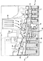
図面の図、特に図1を参照すると、第1及び第2タービン、すなわち全体を符号10で表した第1又は上流側タービンと、それらの流路に沿ってそれらのロータシャフトを互いに結合することによって互いに軸方向に結合された、全体を符号12で表した下流側タービンとが示されている。第1タービン10は、バケット16を支持する複数の軸方向に間隔をおいて配置されたロータホイール14を含み、該ロータホイール14は、パーティション20を支持するダイヤフラム18と共に、多段の第1タービンを形成する。同様に、第2タービン12は、バケット24を支持する複数の軸方向に間隔を置いて配置されたロータホイール22を含み、該ロータホイール22は、パーティション28を支持するダイヤフラム26と共に、多段の第2タービンを形成する。エネルギーを有する流体、例えば蒸気は、矢印27で示した第1流路部分に沿って上流側タービン10の多くの段を通過し、中間のキャビティ30を通り、また下流側タービン12の多くの段で構成された、矢印29で示した第2流路部分を通って、ほぼ軸方向に流れることが分かるであろう。従って、流路部分27及び29とキャビティ30とは、結合されたタービンを通る流路を形成する。更に、それぞれ第1及び第2タービン10及び12の個別のロータシャフト34及び36は、全体を符号38で示したカップリングによって互いに結合される。カップリングは、それぞれのロータシャフトの端部上にフランジ40を含み、フランジ、従ってシャフトは、ボルト41によって互いに相互接続される。更に、一対の半径方向流体(蒸気)導入ポート45(1つのみが示されている)が、共通の外側シェル42を貫通して設けられ、該導入ポート45は、付加的な流体(蒸気)を中間キャビティ30内に導入して流路内の流体に合流させる。
Referring to the drawing figures, and in particular to FIG. 1, the first and second turbines, i.e. first or upstream turbines, generally designated 10, and their rotor shafts are coupled together along their flow paths. And a downstream turbine, generally indicated at 12, which are coupled axially to each other. The
上で述べたように、回転シャフト34及び36とカップリング38とは、キャビティ30内で流路に露出されており、その結果、乱流混合による風損とカップリング38及びその他の部品上の隆起表面に対する衝突による流れはく離に起因する損失とを生じさせる。
As noted above, the rotating
これらの損失を減少させるための従来技術の取り組みが、図2に示されている。図2において、ロータシャフト34及び36の回転軸線に一致した軸線を有する円筒形のカバー46が、直接にカップリング38を覆って配置される。カバー46は、その外面の周りに、半径方向に突出する補強リブ48を有する。この構成によって、回転するシャフト及びカップリングによる損失は、或る程度緩和されたが、この損失は事実上残存し、また円筒形カバーは、流路に沿ったその他の損失には対処しない。
A prior art approach to reducing these losses is shown in FIG. In FIG. 2, a cylindrical cover 46 having an axis that coincides with the rotational axis of the
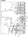
さて、本発明の好ましい実施形態を示す、図1及び図2におけるのと同様の部品を頭に数字1を付けた同じ参照符号で示している図3を参照すると、ここには、上流側タービン110が示されており、該上流側タービン110は、バケット116を支持する軸方向に間隔を置いて配置されたロータホイール114を有し、該ロータホイール114は、パーティション120を支持するダイヤフラム118と共に、個別の軸方向に間隔を置いて配置されたタービン段を形成する。ホイール114は、ロータシャフト134の一部を形成する。同様に、第2又は下流側タービン112は、バケット124を支持するロータホイール122を含み、該ロータホイール122は、パーティション128を支持するダイヤフラム126と共に、個別の軸方向に間隔を置いて配置されたタービン段を形成する。ロータホイール122は、第2ロータシャフト136上に支持される。第1及び第2タービン110及び112は、それぞれ流路部分127及び129を有し、キャビティ130と共にタービンを通る流路を形成する。
Reference is now made to FIG. 3, which shows the preferred embodiment of the present invention and is denoted by the same reference numerals preceded by the numeral 1 with the same parts as in FIGS. 110, the upstream turbine 110 has axially spaced
ロータシャフト134及び136は、従来技術におけるのと同様に、フランジ140と該フランジを互いに固定する一連の円周方向に間隔を置いて配置されたボルト141とを使用して、カップリング138により互いに結合される。また、従来技術におけるのと同様に、共通の外側シェル142には、1つ、好ましくは一対の半径方向の流体又は蒸気インレット145が取付けられており、該流体又は蒸気インレット145は、中間キャビティ130内に流体(蒸気)を導入して、上流側タービン110の出口アニュラス147を出て下流側タービン112の入口アニュラス149へ流れる流体(蒸気)と合流させる。
The
本発明の好ましい実施形態によると、それぞれ第1及び第2タービン110及び112の中間にあるキャビティ130の一部を形成する、全体を符号150で表したディフューザが設けられる。このディフューザ150は、上流側タービン110を出て下流側タービン112内に入る前に、流体(蒸気)から運動エネルギーを回収する。ディフューザ150を形成し、同時に風損及び回転損失を最小にするか又は排除するために、結合されたシャフト134及び136の回転軸線と一致した軸線を有する切頭円錐形断面の形状をした内側カバー152が設けられる。この内側カバー152は、上流側タービン110の出口アニュラス147を出て下流側タービン112の入口アニュラス149に至る流路の内周縁部を定める。つまり、内側カバー152は、上流側タービン110の最終段を形成するバケットの根元半径に隣接したところ(の近傍)から下流側タービンの第1段の内側バンドまで延びる。カバー152は、下流側タービン112の内側シェルにより支持される。従って、中間キャビティ130を通る流路は、シャフト間のカップリング138から実質的に密閉される。
In accordance with a preferred embodiment of the present invention, there is provided a diffuser, generally designated 150, which forms part of a
更に、ディフューザ150を定めるのは、外壁154であり、該外壁154は、上流側タービン110のほぼ軸方向下流側の延長部を形成する。外壁154の内側壁面156は、上流側タービン110を出る流れの外周縁部を一部定める。従って、内側カバー152及び壁面156は流路の周りにアニュラスを形成し、その面積は、下流側タービン112に向けて下流方向に増大している。
Furthermore, it is the
好ましくは2つあるインレットポート145は、中間キャビティ130内に流体(蒸気)を半径方向に導入する。インレットポート145は、上流側及び下流側タービンの両方に共通の外側シェル142の一部を形成する。このインレットポート145は、ほぼ半径方向内向きに向けられた流れが、該流れが外壁154の外側壁面158に遭遇したときに、向きを変えられるように構成されており、流れは、結合キャビティ130に入る前に、軸方向及び円周方向に向きを変えられる。従って、インレット流路が上流側タービンからの軸方向流路と交わる場合に、流れの速度は、混合損失が減少させられるほど十分に低下されている。
Preferably two
上述した好ましい実施形態の結果として、回転損失及び風損は、実質的に最小にされるか又は排除される。更に、上流側タービンの出口アニュラスと下流側タービンの入口アニュラスとの間の流路は、出口及び入口アニュラス147及び149の高さ及び/又は直径がそれぞれ異なるにもかかわらず、それらの間に円滑な流れ移行をもたらす。
As a result of the preferred embodiment described above, rotational and wind losses are substantially minimized or eliminated. Further, the flow path between the upstream turbine outlet annulus and the downstream turbine inlet annulus is smooth between the outlet and
本発明を、現在最も実用的かつ好ましい実施形態であると考えられるものに関連させて説明してきたが、本発明は、開示した実施形態に限定されるべきものではなく、また、特許請求の範囲に記載された符号は、理解容易のためであってなんら発明の技術的範囲を実施例に限縮するものではない。 Although the invention has been described in connection with what is presently considered to be the most practical and preferred embodiments, the invention is not to be limited to the disclosed embodiments and is not limited to the claims. The reference numerals described in the above are for easy understanding and do not limit the technical scope of the invention to the embodiments.
110上流側タービン
112下流側タービン
127上流側タービンの流路部分
129下流側タービンの流路部分
130中間キャビティ
134、136 ロータシャフト
138カップリング
142外側シェル
145半径方向流体インレット
147上流側タービンの出口アニュラス
149下流側タービンの入口アニュラス
150ディフューザ
152内側カバー
154外壁
110
Claims (7)
第1及び第2タービン(110、112)を含み、
前記第1及び第2タービン(110、112)は、該第1タービンに沿った第1流路部分(127)に沿って流れる流体流が、該第1タービンから排出されて該第2タービンに沿った第2流路部分(129)に入るように、流路に沿って軸方向に互いに結合され、またそれぞれのロータ(134、136)と該第1及び第2ロータ間に配置されて該タービンを互いに結合するカップリング(138)とを有しており、
該装置は更に、内側カバー(152)と外壁(154)とを含み、
前記内側カバー(152)は、前記第1タービンの最終段と前記第2タービンの第1段との間で延び、また前記ロータ間の前記カップリングの周りで該カップリングを覆って延びて、該ロータカップリングを前記流路から隔離しかつ前記流体流を前記第1タービンの第1流路部分から前記第2タービンの第2流路部分まで実質的に円滑に移行させ、
前記外壁(154)は、前記第1及び第2タービン間における前記流路の周縁部を定め、
前記内側カバー及び前記外壁は、前記第1及び第2タービン間でかつ前記カップリングの周りにディフューザ(150)を定め、
前記外壁(154)は、鋳造外側タービンシェル(142)の一部を形成している
ことを特徴とする装置。 An apparatus for coupling axially adjacent turbine flow paths together,
Including first and second turbines (110, 112);
The first and second turbines (110, 112) are configured such that a fluid flow flowing along a first flow path portion (127) along the first turbine is discharged from the first turbine to the second turbine. Along the flow path so as to enter a second flow path portion (129) along the flow path and disposed between each rotor (134, 136) and the first and second rotors. A coupling (138) coupling the turbines together,
The apparatus further includes an inner cover (152) and an outer wall (154) ,
The inner cover (152) extends between the last stage of the first turbine and the first stage of the second turbine, and extends around the coupling between the rotors and over the coupling; Isolating the rotor coupling from the flow path and causing the fluid flow to transition substantially smoothly from a first flow path portion of the first turbine to a second flow path portion of the second turbine ;
The outer wall (154) defines a peripheral edge of the flow path between the first and second turbines;
The inner cover and the outer wall define a diffuser (150) between the first and second turbines and around the coupling;
The apparatus, wherein the outer wall (154) forms part of a cast outer turbine shell (142) .
第1及び第2タービン(110、112)を含み、
前記第1及び第2タービン(110、112)は、軸方向に互いに結合され、第1流路部分(127)に沿って流れる流体流が該第1タービンから排出されて該第2タービンの第2流路部分(129)に入るような流路を有し、またそれぞれのロータ(134、136)と該第1及び第2ロータ間に配置されて該タービンを互いに結合するカップリング(138)とを有しており、
該装置は更に、外壁(154)を含み、
前記外壁(154)は、前記第1タービンの最終段と前記第2タービンの第1段との間でかつ前記第1及び第2タービン間の前記流路の周りで該流路を覆って延びて、前記流体流を前記第1タービンの第1流路部分から前記第2タービンの第2流路部分まで実質的に円滑に移行させ、
前記外壁(154)は、鋳造外側タービンシェル(142)の一部を形成している
ことを特徴とする装置。 An apparatus for coupling turbines together,
Including first and second turbines (110, 112);
The first and second turbines (110, 112) are axially coupled to each other, and a fluid flow flowing along the first flow path portion (127) is exhausted from the first turbine and the second turbine is connected to the second turbine. Coupling (138) having a flow path to enter two flow path portions (129) and disposed between each rotor (134, 136) and the first and second rotors to couple the turbines to each other And
The apparatus further includes an outer wall (154),
The outer wall (154) extends over the flow path between the last stage of the first turbine and the first stage of the second turbine and around the flow path between the first and second turbines. Substantially smoothly transitioning the fluid flow from the first flow path portion of the first turbine to the second flow path portion of the second turbine ,
The apparatus, wherein the outer wall (154) forms part of a cast outer turbine shell (142) .
Applications Claiming Priority (1)
| Application Number | Priority Date | Filing Date | Title |
|---|---|---|---|
| US10/288,301 US6783321B2 (en) | 2002-11-06 | 2002-11-06 | Diffusing coupling cover for axially joined turbines |
Publications (3)
| Publication Number | Publication Date |
|---|---|
| JP2004156617A JP2004156617A (en) | 2004-06-03 |
| JP2004156617A5 JP2004156617A5 (en) | 2006-12-21 |
| JP4458816B2 true JP4458816B2 (en) | 2010-04-28 |
Family
ID=32175880
Family Applications (1)
| Application Number | Title | Priority Date | Filing Date |
|---|---|---|---|
| JP2003376344A Expired - Fee Related JP4458816B2 (en) | 2002-11-06 | 2003-11-06 | Diffusion bonded cover for axially coupled turbines |
Country Status (7)
| Country | Link |
|---|---|
| US (1) | US6783321B2 (en) |
| JP (1) | JP4458816B2 (en) |
| KR (1) | KR100847941B1 (en) |
| CN (1) | CN100354503C (en) |
| CZ (1) | CZ302462B6 (en) |
| DE (1) | DE10350230B4 (en) |
| RU (1) | RU2331772C2 (en) |
Families Citing this family (8)
| Publication number | Priority date | Publication date | Assignee | Title |
|---|---|---|---|---|
| US7488153B2 (en) * | 2002-07-01 | 2009-02-10 | Alstom Technology Ltd. | Steam turbine |
| GB0616832D0 (en) * | 2006-08-25 | 2006-10-04 | Alstom Technology Ltd | Turbomachine |
| JP4305518B2 (en) * | 2007-02-06 | 2009-07-29 | トヨタ自動車株式会社 | Chip turbine drive fan |
| US8152437B2 (en) * | 2008-03-10 | 2012-04-10 | General Electric Company | Interface member for a power plant |
| EP3296506A1 (en) * | 2016-09-20 | 2018-03-21 | Siemens Aktiengesellschaft | Assembly for feed of an additional mass flow into a main mass flow |
| US11851202B1 (en) | 2022-06-23 | 2023-12-26 | Pratt & Whitney Canada Corp. | Aircraft engine, gas turbine intake therefore, and method of guiding exhaust gasses |
| US11891947B2 (en) | 2022-06-23 | 2024-02-06 | Pratt & Whitney Canada Corp. | Aircraft engine, gas turbine intake therefore, and method of guiding exhaust gasses |
| US11821361B1 (en) | 2022-07-06 | 2023-11-21 | Pratt & Whitney Canada Corp. | Gas turbine intake for aircraft engine and method of inspection thereof |
Family Cites Families (8)
| Publication number | Priority date | Publication date | Assignee | Title |
|---|---|---|---|---|
| GB221781A (en) * | 1923-09-15 | 1925-08-27 | Erste Bruenner Maschinen Fab | Improvements in and relating to steam and gas turbines |
| GB723882A (en) * | 1951-09-05 | 1955-02-16 | Vickers Electrical Co Ltd | Improvements in the construction of rotors for steam- and gas-turbines |
| US2919891A (en) * | 1957-06-17 | 1960-01-05 | Gen Electric | Gas turbine diaphragm assembly |
| JPS57168005A (en) * | 1981-04-10 | 1982-10-16 | Hitachi Ltd | Rotor structue for axial machines |
| DE19701020A1 (en) * | 1997-01-14 | 1998-07-23 | Siemens Ag | Steam turbine |
| EP1068429B1 (en) | 1998-04-06 | 2004-06-16 | Siemens Aktiengesellschaft | Steam turbine |
| JP3772019B2 (en) | 1998-04-21 | 2006-05-10 | 株式会社東芝 | Steam turbine |
| CN2505601Y (en) * | 2001-12-05 | 2002-08-14 | 财团法人工业技术研究院 | Spindle shaft of core rotor of gas-turbine engine |
-
2002
- 2002-11-06 US US10/288,301 patent/US6783321B2/en not_active Expired - Lifetime
-
2003
- 2003-10-27 DE DE10350230A patent/DE10350230B4/en not_active Expired - Fee Related
- 2003-11-05 RU RU2003132422/06A patent/RU2331772C2/en not_active IP Right Cessation
- 2003-11-05 CZ CZ20033009A patent/CZ302462B6/en not_active IP Right Cessation
- 2003-11-05 KR KR1020030077829A patent/KR100847941B1/en not_active IP Right Cessation
- 2003-11-06 CN CNB2003101181612A patent/CN100354503C/en not_active Expired - Fee Related
- 2003-11-06 JP JP2003376344A patent/JP4458816B2/en not_active Expired - Fee Related
Also Published As
| Publication number | Publication date |
|---|---|
| KR100847941B1 (en) | 2008-07-22 |
| RU2003132422A (en) | 2005-05-20 |
| DE10350230B4 (en) | 2012-07-19 |
| CN100354503C (en) | 2007-12-12 |
| CZ20033009A3 (en) | 2004-06-16 |
| CN1508397A (en) | 2004-06-30 |
| US6783321B2 (en) | 2004-08-31 |
| JP2004156617A (en) | 2004-06-03 |
| KR20040040371A (en) | 2004-05-12 |
| DE10350230A1 (en) | 2004-05-27 |
| US20040086375A1 (en) | 2004-05-06 |
| RU2331772C2 (en) | 2008-08-20 |
| CZ302462B6 (en) | 2011-06-01 |
Similar Documents
| Publication | Publication Date | Title |
|---|---|---|
| US8317467B2 (en) | Radial channel diffuser for steam turbine exhaust hood | |
| CN101839148A (en) | Steam turbine rotor blade and corresponding steam turbine | |
| EP3258115B1 (en) | Service routing configuration for gas turbine engine diffuser systems | |
| US3149470A (en) | Low pressure turbine exhaust hood | |
| JP4820492B2 (en) | Method and apparatus for supplying a cooling air flow in a turbine engine | |
| JP5535562B2 (en) | Discharge scroll and turbo machine | |
| US6196793B1 (en) | Nozzle box | |
| JP4458816B2 (en) | Diffusion bonded cover for axially coupled turbines | |
| US6332754B1 (en) | Steam turbine | |
| US2641442A (en) | Turbine | |
| KR920012703A (en) | Suction Casing for Axial Single Flow High Pressure Steam Turbine | |
| CN101769173A (en) | Methods, systems and/or apparatus relating to steam turbine exhaust diffusers | |
| JP4918034B2 (en) | Gas turbine compression system and compressor structure | |
| RU2538215C2 (en) | Outlet unit for steam turbine | |
| EP3265653B1 (en) | Turbine for organic rankine cycles with axial input and output | |
| US6854954B2 (en) | Methods and apparatus for assembling turbine engines | |
| IT202000013609A1 (en) | COMPONENT OF A TURBINE ENGINE WITH AN ASSEMBLY OF DEFLECTORS | |
| JP2005240713A (en) | Centrifugal compressor | |
| US6425737B1 (en) | Turbine | |
| JPH0441907A (en) | Exhaust diffuser for turbine | |
| JP6239908B2 (en) | Exhaust system for use in turbine and assembly method thereof | |
| CA1095001A (en) | Rotary compressors | |
| JP2018105220A (en) | Turbine and gas turbine | |
| JPS6260903A (en) | Diaphragm for steam turbine | |
| JPS60166794A (en) | Centrifugal compressor |
Legal Events
| Date | Code | Title | Description |
|---|---|---|---|
| A521 | Request for written amendment filed |
Free format text: JAPANESE INTERMEDIATE CODE: A523 Effective date: 20061106 |
|
| A621 | Written request for application examination |
Free format text: JAPANESE INTERMEDIATE CODE: A621 Effective date: 20061106 |
|
| A131 | Notification of reasons for refusal |
Free format text: JAPANESE INTERMEDIATE CODE: A131 Effective date: 20090519 |
|
| A601 | Written request for extension of time |
Free format text: JAPANESE INTERMEDIATE CODE: A601 Effective date: 20090812 |
|
| RD02 | Notification of acceptance of power of attorney |
Free format text: JAPANESE INTERMEDIATE CODE: A7422 Effective date: 20090812 |
|
| RD04 | Notification of resignation of power of attorney |
Free format text: JAPANESE INTERMEDIATE CODE: A7424 Effective date: 20090812 |
|
| A602 | Written permission of extension of time |
Free format text: JAPANESE INTERMEDIATE CODE: A602 Effective date: 20090818 |
|
| A601 | Written request for extension of time |
Free format text: JAPANESE INTERMEDIATE CODE: A601 Effective date: 20090916 |
|
| A602 | Written permission of extension of time |
Free format text: JAPANESE INTERMEDIATE CODE: A602 Effective date: 20090924 |
|
| A521 | Request for written amendment filed |
Free format text: JAPANESE INTERMEDIATE CODE: A523 Effective date: 20091016 |
|
| TRDD | Decision of grant or rejection written | ||
| A01 | Written decision to grant a patent or to grant a registration (utility model) |
Free format text: JAPANESE INTERMEDIATE CODE: A01 Effective date: 20100112 |
|
| A01 | Written decision to grant a patent or to grant a registration (utility model) |
Free format text: JAPANESE INTERMEDIATE CODE: A01 |
|
| A61 | First payment of annual fees (during grant procedure) |
Free format text: JAPANESE INTERMEDIATE CODE: A61 Effective date: 20100209 |
|
| R150 | Certificate of patent or registration of utility model |
Free format text: JAPANESE INTERMEDIATE CODE: R150 |
|
| FPAY | Renewal fee payment (event date is renewal date of database) |
Free format text: PAYMENT UNTIL: 20130219 Year of fee payment: 3 |
|
| FPAY | Renewal fee payment (event date is renewal date of database) |
Free format text: PAYMENT UNTIL: 20130219 Year of fee payment: 3 |
|
| FPAY | Renewal fee payment (event date is renewal date of database) |
Free format text: PAYMENT UNTIL: 20140219 Year of fee payment: 4 |
|
| R250 | Receipt of annual fees |
Free format text: JAPANESE INTERMEDIATE CODE: R250 |
|
| R250 | Receipt of annual fees |
Free format text: JAPANESE INTERMEDIATE CODE: R250 |
|
| R250 | Receipt of annual fees |
Free format text: JAPANESE INTERMEDIATE CODE: R250 |
|
| R250 | Receipt of annual fees |
Free format text: JAPANESE INTERMEDIATE CODE: R250 |
|
| LAPS | Cancellation because of no payment of annual fees |