JP4457590B2 - Brake system for vehicles - Google Patents
Brake system for vehicles Download PDFInfo
- Publication number
- JP4457590B2 JP4457590B2 JP2003201492A JP2003201492A JP4457590B2 JP 4457590 B2 JP4457590 B2 JP 4457590B2 JP 2003201492 A JP2003201492 A JP 2003201492A JP 2003201492 A JP2003201492 A JP 2003201492A JP 4457590 B2 JP4457590 B2 JP 4457590B2
- Authority
- JP
- Japan
- Prior art keywords
- maximum deceleration
- force
- brake
- deceleration control
- maximum
- Prior art date
- Legal status (The legal status is an assumption and is not a legal conclusion. Google has not performed a legal analysis and makes no representation as to the accuracy of the status listed.)
- Expired - Fee Related
Links
Images


Landscapes
- Regulating Braking Force (AREA)
Description
【0001】
【発明の属する技術分野】
本発明は、車両用のブレーキシステムに関するものであり、特に、制動時における車輪の過大なスリップを防止することにより、車両を可及的に大きな減速度で減速し得るブレーキシステムに関するものである。
【0002】
【従来の技術】
この種のブレーキシステムとして、アンチロック制御部を備えたものが特許文献1および2により知られている。特許文献1には、アンチロック制御部を備えたブレーキシステムにおいて、アンチロック制御における目標スリップ率に微小な交番変動を付加し、その微小な変動とそれに伴って生じる路面摩擦係数の微小な変動との幅および位相の関係から、路面の摩擦係数のスリップ率に対する増加率を算出し、その増加率の大きさに基づいてブレーキ作動力を増加,保持,減少させ、かつ、その増加または減少の速度を加減することによって、最短の制動距離を実現することが記載されている。また、特許文献2には、アンチロック制御部を備えたブレーキシステムにおいて、実際のヨーレイトの目標ヨーレイトからの偏差に応じてアンチロック制御における目標スリップ率を小さく制限し、コーナリングフォースを確保することが記載されている。
また、特許文献3には、車輪のタイヤに作用する力を検出する技術が記載されている。
【0003】
【特許文献1】
特開平5−39021号公報
【特許文献2】
特開平5−85327号公報
【特許文献3】
特開2003−14563号公報
【特許文献4】
特開2001−88576号公報
【特許文献5】
特開平10−297450号公報
【0004】
アンチロック制御部を備えたブレーキシステムによれば、アンチロック制御部を備えないものによる場合に比較して、車両を短い距離で停止させ得る場合が多い。車輪の回転を抑制するブレーキの作動力が、路面の摩擦係数(厳密にはタイヤと路面との間に期待し得る最大摩擦係数)との関係において過大である場合には、車輪のスリップが過大となり、車輪と路面との間の実際の摩擦力が低下して、車両を停止させるに必要な距離が長くなってしまうのであるが、ブレーキシステムがアンチロック制御部を備えていれば、その不都合を回避し得るのである。アンチロック制御部が、例えば、スリップ率が設定スリップ率以上になればブレーキ作動力を減少させ、その結果、所定のスリップの回復傾向が生じればブレーキ作動力を増加させるというように、スリップ状態の変化に応じてブレーキ作動力を増減させることにより、スリップが過大となることを防止するからである。
【0005】
【発明が解決しようとする課題,課題解決手段および効果】
しかしながら、従来のアンチロック制御部は、上記のように、ブレーキ作動力を増減させるものであるため、ブレーキ作動力がやや不適切な大きさである時期があることを避け得ず、その分、車両を停止させるに必要な距離が長くなるうらみがあった。本発明は、以上の事情を背景とし、アンチロック制御部によるよりさらに有効に路面の摩擦係数、すなわちタイヤと路面との間に期待できる最大摩擦係数を利用でき、車両を停止させるに必要な距離をさらに短縮できるブレーキシステムを得ることを課題としてなされたものであり、本発明によって、(1)車輪の回転を抑制するブレーキと、(2)運転者ができる限り大きな減速度で車両を減速させることを要求する最大減速度要求を検出する最大減速度要求検出部と、(3)少なくとも、最大減速度要求検出部により最大減速度要求が検出された場合に、ブレーキの作動力を最大減速度が得られる大きさに保持する最大減速度制御を行う最大減速度制御部とを含み、最大減速度制御部が、(a)最大減速度要求が検出された時点に走行中の路面と車輪との間に期待できる最大摩擦係数に対応するブレーキの作動力である保持ブレーキ作動力が取得できるまで前記ブレーキの作動力を増大させて保持ブレーキ作動力を取得する初期段階と、(b)その初期段階に続いてブレーキの作動力を一旦保持ブレーキ作動力より小さいブレーキ作動力まで減少させる中間段階と、(c)その中間段階に続いてブレーキの作動力を保持ブレーキ作動力まで増大させた後、最大減速制御の解除条件が成立するまでブレーキの作動力を増減させることなく保持ブレーキ作動力に保持する保持段階とを実行することを特徴とするブレーキシステムが得られる。
このように、保持段階においてはブレーキの作動力を増減させることなく、初期段階に取得した、最大減速度が得られる保持ブレーキ作動力に保持すれば、従来のアンチロック制御におけるように、制動中にブレーキ作動力がやや不適切な大きさである時期が存在することが無くなり、タイヤと路面との間に期待し得る最大摩擦係数を継続して利用することができ、車両を停止させるに必要な距離をさらに短縮できる効果が得られる。
【0006】
本発明によれば、さらに、下記各態様のブレーキシステムが得られる。各態様は請求項と同様に、項に区分し、各項に番号を付し、必要に応じて他の項の番号を引用する形式で記載する。これは、あくまでも本発明の理解を容易にするためであり、本明細書に記載の技術的特徴およびそれらの組合わせが以下の各項に記載のものに限定されると解釈されるべきではない。また、一つの項に複数の事項が記載されている場合、それら複数の事項を常に一緒に採用しなければならないわけではない。一部の事項のみを選択して採用することも可能なのである。
【0007】
(1)車輪の回転を抑制するブレーキと、
運転者ができる限り大きな減速度で車両を減速させることを要求する最大減速度要求を検出する最大減速度要求検出部と、
少なくとも、前記最大減速度要求検出部により前記最大減速度要求が検出された場合に、前記ブレーキの作動力を最大減速度が得られる大きさに保持する最大減速度制御を行う最大減速度制御部と
を含むことを特徴とするブレーキシステム。
最大減速度制御部は、少なくとも、最大減速度要求検出部により運転者の最大減速度要求が検出された場合に、ブレーキの作動力を最大減速度が得られる大きさに保持する。従来のアンチロック制御部におけるように、車輪のスリップ率の変動に応じてブレーキ作動力を増減させるわけではなく、適正値に保持するのであるため、安定的に最大減速度が得られる。ある走行速度から所望の走行速度(0を含む)まで減少させるに必要な距離を最短にし得るのである。
(2)前記最大減速度要求検出部が、少なくとも運転者による制動操作部材の操作力が設定制動操力より大きい場合に、前記最大減速度要求を検出するものである (1)項に記載のブレーキシステム。
制動操作部材の操作力は、ブレーキを作用させる向きの操作力を正とする。操作力が大きい場合には、運転者が最大減速度で車両を減速させることを要求していると考えることは妥当なことである。
(3)前記最大減速度要求検出部が、少なくとも運転者による制動操作部材の操作速度が正の設定制動操作速度より大きい場合に、前記最大減速度要求を検出するものである (1)項または (2)項に記載のブレーキシステム。
制動操作部材の操作速度はブレーキを作用させる向きの操作速度を正とする。操作速度が大きい場合には運転者が最大減速度で車両を減速させることを要求していることが多いため、操作速度に基づいて最大減速度要求を検出することは妥当なことである。ブレーキ部材の操作速度は操作力が大きくなるに従って低下するのが普通であるため、設定制動操作速度は一定値とすることも可能であるが、制動操作部材の操作速度は、操作力が大きい領域では小さい領域に比較して小さくなるのが普通であるため、操作力が大きい場合には小さい場合に比較して小さい値に設定されることが望ましい。この場合、設定制動操作速度は連続的に変えられても、段階的に変えられてもよい。
(4)運転操作状態検出部,車両走行状態検出部および路面状態検出部の少なくとも1つを含み、その少なくとも1つが最大減速度制御許容状態を検出している場合に最大減速度制御を許可する最大減速度制御許可部を含み、その最大減速度制御許可部により前記最大減速度制御が許可されている場合に、前記最大減速度制御部が前記最大減速度制御を行う (1)項ないし (3)項に記載のブレーキシステム。
ブレーキシステムが、後述するように、最大減速度制御部と共にアンチロック制御部を含み、最大減速度制御部による制御では車輪のスリップが過大になる場合には、最大減速度制御部の作動を停止させ、アンチロック制御部を作動させることができる構成のものである場合には、最大減速度制御部を、例えば、ブレーキ作動力を乾燥アスファルト路に適した大きさに保持するものとしておくことによって、乾燥アスファルト路上において最大減速度を得ることができるブレーキシステムが得られ、最大減速度制御許可部は不可欠ではない。しかし、最大減速度制御許可部を設ければ、最大減速度制御部が適切な時期にのみの作動するブレーキシステムが得られる。運転操作状態検出部,車両走行状態検出部、路面状態検出部等が最大減速度制御許容状態を検出するための条件として、少なくとも、運転操作状態,車両走行状態,路面状態等が定常状態にあることが含まれることが望ましい。最大減速度制御は、原則として定常状態において実行されることが望ましいのである。
(5)少なくとも前記運転操作状態検出部が、少なくとも運転者による操舵速度の絶対値が正の設定操舵速度より小さい場合に、前記最大減速度制御許容状態を検出するものである (4)項に記載のブレーキシステム。
操舵速度の絶対値が正の設定操舵速度より小さい場合には、運転者による操舵操作が定常状態にあるとみなすことができる。操舵角および操舵速度はステアリングホイール等の操舵部材が右に操作される場合と左に操作される場合とで、符号が正負逆にされるのが普通であり、絶対値で論ずれば、いずれの向きに操舵される場合でも同様に扱うことができる。
(6)少なくとも前記運転操作状態検出部が、少なくとも運転者により保舵が行われている場合に、前記最大減速度制御許容状態を検出するものである (5)項に記載のブレーキシステム。
(7)少なくとも前記運転操作状態検出部が、操舵角の絶対値が最大操舵角の80%以上であることを検出している状態では、前記最大減速度制御許容状態を検出しないものである (4)項ないし (6)項に記載のブレーキシステム。
操舵角の絶対値が最大操舵角の80%以上であることを検出している場合には、たとえ操舵速度の絶対値が小さい場合でも最大減速度制御は行われないようにすることが望ましく、50%以上であることを検出している場合に行われないようにすることがさらに望ましい。
(8)少なくとも前記運転操作状態検出部が、少なくとも運転者による制動操作部材の操作速度の絶対値が正の設定制動操作速度より小さい場合に、前記最大減速度制御許容状態を検出するものである (4)項ないし (7)項のいずれかに記載のブレーキシステム。
制動操作部材の操作速度の絶対値が小さい場合には、運転者による制動操作が定常状態にあるとみなすことができる。本項の特徴は、後に実施形態の項において説明するように、最大減速度制御を解除すべきか否かの判定に利用して特に有効なものである。
(9)少なくとも前記車両走行状態検出部が、少なくとも車体の横加速度の絶対値が正の設定横加速度より小さいことを検出している場合に、前記最大減速度制御許容状態を検出するものである (4)項ないし (8)項のいずれかに記載のブレーキシステム。
横加速度は車両の旋回方向によって符号が正負逆になる。いずれにしても、車体の横加速度の絶対値が正の設定横加速度より小さい場合には、たとえ車両が旋回していても最大減速度で減速させ得ることが多いため、車両走行状態検出部が最大減速度制御許容状態を検出するようにすることは妥当なことである。
(10)少なくとも前記車両走行状態検出部が、少なくとも車体の横加速度の変化速度の絶対値が正の設定変化速度より小さい場合に、前記最大減速度制御許容状態を検出するものである (4)項ないし (9)項のいずれかに記載のブレーキシステム。
横加速度の変化が小さい場合には、たとえ旋回中であっても車両の走行状態が定常状態にあるとみなし得るため、車両走行状態検出部が最大減速度制御許容状態を検出するようにするのである。
(11)少なくとも前記車両走行状態検出部が、少なくとも車体のヨーレイトの絶対値が正の設定ヨーレイトより小さい場合に、前記最大減速度制御許容状態を検出するものである (4)項ないし(10)項のいずれかに記載のブレーキシステム。
(9)項の説明が本項にも当てはまる。
(12)少なくとも前記車両走行状態検出部が、少なくとも車体のヨーレイトの変化速度の絶対値が正の設定変化速度より小さい場合に、前記最大減速度制御許容状態を検出するものである (4)項ないし(11)項のいずれかに記載のブレーキシステム。
(10)項の説明が本項にも当てはまる。
(13)少なくとも前記車両走行状態検出部が、少なくとも前記車輪の回転加速度の絶対値が正の設定加速度より小さい場合に、最大減速度制御許容状態を検出するものである (2)項ないし(11)項のいずれかに記載のブレーキシステム。
車輪の回転加速度が正の設定加速度より大きくなった場合には、制動部材の操作力が減少させられたか、あるいは駆動源の駆動力が増された可能性が高いため、最大減速度制御が解除されるようにすることが望ましい。路面の最大摩擦係数が大きくなった場合にも車輪の回転加速度が正の設定加速度より大きくなる。この場合には車両走行状態検出部ではなく路面状態検出部であることになるが、いずれにしても最大減速度制御が解除されるようにすることが望ましいことには変わりがないため、実用上の不都合はない。
(14)少なくとも前記路面状態検出部が、少なくとも左車輪が接触している路面の摩擦係数と右車輪が接触している路面の摩擦係数との差である摩擦係数左右差を検出する摩擦係数左右差検出部を備え、その摩擦係数左右差検出部により前記摩擦係数左右差の絶対値が正の設定係数差より小さい場合に、前記最大減速度制御許容状態を検出するものである (4)項ないし(12)項のいずれかに記載のブレーキシステム。
左右の車輪が接触している路面の摩擦係数(最大摩擦係数)の差が大きい場合(またぎ路と称する)には、最大減速度制御が実行されることは好ましくない。
(15)前記摩擦係数左右差検出部が、少なくとも、左右車輪のブレーキ作動力差を検出する作動力差検出部を備え、その作動力差検出部により検出されたブレーキ作動力差の絶対値が正の設定作動力差より小さい場合に、前記摩擦係数左右差の絶対値が正の設定係数差より小さいことを検出する手段を含む(14)項に記載のブレーキシステム。
(16)前記摩擦係数左右差検出部が、少なくとも、左右車輪の回転速度差を検出する回転速度差検出部を備え、その回転速度差検出部により検出された回転速度差の絶対値が正の設定速度差より小さい場合に、前記摩擦係数左右差の絶対値が正の設定係数差より小さいことを検出する手段を含む(14)項または(15)項に記載のブレーキシステム。
(17)前記摩擦係数左右差検出部が、少なくとも、左車輪のブレーキ作動力関連量と車輪スリップ関連量との比と右車輪のブレーキ作動力関連量と車輪スリップ関連量との比との差を検出する比差検出部を備え、その比差検出部により検出された比差の絶対値が正の設定比差より小さい場合に、前記摩擦係数左右差の絶対値が正の設定係数差より小さいことを検出する手段を含む(14)項ないし(16)項のいずれかに記載のブレーキシステム。
ブレーキ作動力関連量には、例えば、ブレーキ作動力自体,マスタ圧,車輪に対する接線方向力(車輪の回転軸線と直交しかつその車輪に接する方向の力)等、ブレーキ作動力の増減と共に増減する量が該当し、車輪スリップ関連量には、例えば、車輪のスリップ量,スリップ率,回転減速度等、スリップの増減と共に増減する量が該当する。ブレーキ作動力関連量と車輪スリップ関連量との一方のみに基づいてまたぎ路を検出することも可能であるが、左車輪のブレーキ作動力関連量と車輪スリップ関連量との比と右車輪のブレーキ作動力関連量と車輪スリップ関連量との比との差に基づいて検出する方が検出の信頼性が高い。
(18)前記最大減速度制御許可部が、前記最大減速度制御が行われていない状態において、前記最大減速度要求検出部により前記最大減速度要求が検出され、かつ、前記運転操作状態検出部,車両走行状態検出部および路面状態検出部の少なくとも1つにより最大減速度制御許容状態が検出された場合に、最大減速度制御の開始を許可する最大減速度制御開始許可部を含む (4)項ないし(17)項のいずれかに記載のブレーキシステム。
(19)前記最大減速度制御許可部が、前記最大減速度制御が行われている状態において、前記最大減速度要求検出部により前記最大減速度要求が検出されなくなることと、前記運転操作状態検出部,車両走行状態検出部および路面状態検出部の少なくとも1つにより最大減速度制御許容状態が検出されなくなることとの少なくとも一方が生じた場合に、最大減速度制御の終了を指令する最大減速度制御終了指令部を含む (4)項ないし(18)項のいずれかに記載のブレーキシステム。
(20)前記ブレーキの作動力を制御することにより、前記車輪の制動時におけるスリップが過大になることを回避するアンチロック制御部と、
そのアンチロック制御部と前記最大減速度制御部とを選択する選択部と
を含む (1)項ないし(19)項のいずれかに記載のブレーキシステム。
アンチロック制御も車輪のスリップが過大となることを抑制する制御ではあるが、スリップ状態を監視しつつブレーキ作動力を増減させるものであるため、ブレーキ作動力を最適な大きさに保持する最大減速度制御に比較すれば、車両の減速度が小さくなることを避け得ない。従って、最大減速度制御が、車輪のスリップ状態を第一スリップ状態に保持すべく制御する第一スリップ制御部であり、アンチロック部が、第一スリップ状態より車輪のスリップが小さい第二スリップ状態に近づけるべく制御する第二スリップ制御部であると考えることもできる。その場合、ブレーキシステムを、運転操作状態検出部,車両走行状態検出部および路面状態検出部の少なくとも1つを備えて、その少なくとも1つが最大減速度制御制御許容状態を検出している場合に第一スリップ制御部を選択し、最大減速度制御制御許容状態を検出していない場合に第二スリップ制御部を選択する選択部を含むものとすることが望ましい。
(21)前記一定に保持されるべきブレーキ作動力である保持ブレーキ作動力を決定する保持ブレーキ作動力決定部を含む (1)項ないし(20)項のいずれかに記載のブレーキシステム。
(22)前記車輪に作用する上下方向の力である上下力を検出する上下力検出装置と、
前記車輪に作用する水平方向の力である水平力を検出する水平力検出装置と
を含み、前記保持ブレーキ作動力決定部が、それら上下力検出装置および水平力検出装置により検出された上下力および水平力に基づいて前記保持ブレーキ作動力を決定する(21)項に記載のブレーキシステム。
摩擦係数
(23)前記水平力検出装置が、前記車輪の回転軸線と直交しかつその車輪に接する方向の力である接線方向力を前記水平力として検出する接線方向力検出装置を含む(22)項に記載のブレーキシステム。
(24)前記車輪のスリップ率を検出するスリップ率検出装置を含み、そのスリップ率検出装置により検出されたスリップ率と、前記上下力検出装置および水平力検出装置により検出された前記上下力および水平力とに基づいて、前記保持ブレーキ作動力決定部が前記保持ブレーキ作動力を決定するスリップ率・水平力依拠作動力決定部を含む(21)項ないし(23)項に記載のブレーキシステム。
(25)車輪の回転を抑制するブレーキと、
そのブレーキの作動力を制御することにより、前記車輪の制動時におけるスリップが過大になることを回避するアンチロック制御部と、
運転操作状態検出部,車両走行状態検出部および路面状態検出部の少なくとも1つを含み、その少なくとも1つが定常状態を検出している場合に車両が定常走行状態にあることを検出する定常走行検出部と、
その定常走行検出部により前記定常走行状態が検出されている状態では、前記アンチロック制御部を、前記車輪のスリップ状態を第一スリップ状態に保持すべく制御し、定常走行状態が検出されない状態では前記第一スリップ状態より前記車輪のスリップが小さい第二スリップ状態に近づけるべく制御する制御モード変更部と
を含むことを特徴とするブレーキシステム。
アンチロック制御部は制御モード変更部により制御モードを変更され、車輪のスリップ状態を第一スリップ状態に保持すべく制御する第一制御モードと、第一スリップ状態より車輪のスリップが小さい第二スリップ状態に近づけるべく制御する第二制御モードとで作動する。第一制御モードで作動するアンチロック制御部は、 (1)項ないし(24)項に記載のブレーキシステムにおける最大減速度制御部を包含する。
(26)運転者が最大減速度で車両を減速させることを要求する最大減速度要求を検出する最大減速度要求検出部を含み、その最大減速度要求検出部が最大減速度要求を検出しており、かつ、前記定常走行検出部が前記定常走行状態を検出している間、前記制御モード変更部が前記アンチロック制御部を前記第一スリップ状態に保持すべく制御する(25)項に記載のブレーキシステム。
【0008】
【発明の実施の形態】
以下、本発明の一実施形態であるブレーキシステムを図面に基づいて詳細に説明する。
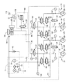
本ブレーキシステムは、図1に示すように、制動操作部材としてのブレーキペダル10と、動力式液圧源としてのポンプ装置12と、マスタシリンダ14と、左右前輪16,17に設けられたブレーキシリンダ18,19を含むブレーキ20,21と、左右後輪24,25に設けられたブレーキシリンダ26,27を含むブレーキ28,29とを含む。なお、本実施形態においては、前輪16,17が駆動輪であり、前輪駆動車なのである。
ブレーキ20,21,28,29は、摩擦ブレーキであり、液圧により非回転体に保持された摩擦係合部材が車輪と共に回転させられるブレーキ回転体に押し付けられることによって、車輪16,17,24,25の回転を抑制する液圧ブレーキである。
【0009】
ポンプ装置12は、ポンプ30と、そのポンプ30を駆動するポンプモータ32と、アキュムレータ34とを含む。ポンプ30は、リザーバ36の作動液を加圧して吐出するものであり、ポンプ30から吐出された高圧の作動液がアキュムレータ34に蓄えられる。アキュムレータ34の液圧はアキュムレータ圧センサ38によって検出されるが、ポンプモータ32は、アキュムレータ圧センサ38による検出液圧が予め定められた設定範囲内に保たれるように制御される。ポンプ30の吐出圧側には、ポンプ30への作動液の逆流を防止するための逆止弁39が設けられている。また、ポンプ装置12の高圧側と低圧側との間にはリリーフ弁40が設けられ、ポンプ30の吐出圧が過大になることが回避される。
なお、ポンプ30は、プランジャポンプであっても、ギヤポンプであってもよい。
【0010】
マスタシリンダ14は、2つの加圧室を含むタンデム式のものであり、ブレーキペダル10が踏み込まれると、2つの加圧室には同じ高さの液圧が発生させられる。一方の加圧室には液通路44により左後輪24のブレーキシリンダ26が接続され、他方の加圧室には、液通路46により左前輪16のブレーキシリンダ18が接続される。
【0011】
液通路44,46の途中には、それぞれマスタ遮断弁50,52が設けられている。また、左右前輪16,17のブレーキシリンダ18,19、左右後輪24,25のブレーキシリンダ26,27は、それぞれ、連通路54,56によって接続されており、連通路54,56には、それぞれ、連通弁58,60が設けられている。
マスタ遮断弁50,52は、コイル62に電流が供給されない場合に開状態にある常開弁であり、連通弁58,60もコイル64に電流が供給されない場合に開状態にある常開弁である。この状態においては、マスタシリンダ14の作動液が左右前後輪16,17,24,25のブレーキシリンダ18,19,26,27に供給され、ブレーキ20,21,28,29が作動させられる。
【0012】
液通路46のマスタ遮断弁52より上流側の部分にはシミュレーション装置66が設けられている。シミュレーション装置66は、ストロークシミュレータ67とシミュレータ用開閉弁68とを含むものであり、液通路46に、ストロークシミュレータ67がシミュレータ用開閉弁68を経て接続されている。シミュレータ用開閉弁68は、コイル69に電流が供給されない場合に閉状態にある常閉弁である。
【0013】
前記ポンプ装置12は、液通路72を経てすべてのブレーキシリンダ18,19,26,27に接続される。また、ブレーキシリンダ18,19,26,27の各々には、それぞれ、個別液圧制御弁装置としてのリニアバルブ装置80〜86が設けられている。リニアバルブ装置80〜86は、それぞれ、増圧用リニアバルブ90と減圧用リニアバルブ92とを含む。増圧用リニアバルブ90が上述の液通路72に設けられ、減圧用リニアバルブ92がブレーキシリンダ18,19,26,27とリザーバ36とを接続する液通路94に設けられる。リニアバルブ装置80〜86の制御により、ブレーキシリンダ18,19,26,27の液圧が、ポンプ装置12の作動液を利用して別個に制御される。
【0014】
増圧用リニアバルブ90,減圧用リニアバルブ92は、図2に示すように、いずれも常閉弁であり、コイル100を含むソレノイド102と、弁子104および弁座106とスプリング108とを含むシーティング弁110とを含む。
シーティング弁110においては、弁子104を弁座106に着座させる方向にスプリング108の付勢力が作用するとともに、弁子104を弁座106から離間させる方向に当該リニアバルブの前後の液圧差に応じた差圧作用力とコイル100への供給電流量に応じた電磁駆動力とが作用する。
コイル100に電流が供給されない状態において、差圧作用力がスプリング108の付勢力より小さい場合は、弁子104が弁座106に着座させられた閉状態に保たれるが、差圧作用力が付勢力より大きい場合は、弁子104が弁座106から離間させられる。
コイル100に電流が供給される状態においては、弁子104の弁座106に対する相対位置が、電磁駆動力,スプリング108の付勢力,差圧作用力の関係によって決まるのであり、相対位置が電磁駆動力の制御によって制御される。
【0015】
増圧用リニアバルブ90に加えられる差圧作用力は、ポンプ装置12の液圧(アキュムレータの液圧)とブレーキシリンダ液圧との差圧に応じた力であり、減圧用リニアバルブ92に加えられる差圧作用力は、ブレーキシリンダ液圧とリザーバ36の液圧との差圧に応じた力であり、リザーバ36の液圧はほぼ大気圧であるため、ブレーキシリンダの液圧に応じた力になる。いずれにしても、電磁駆動力を制御すれば、すなわちコイル100への供給電流を制御すれば、ブレーキシリンダの液圧を制御することができる。
【0016】
また、液通路72の増圧用リニアバルブ90とポンプ装置12との間には、液圧センサ120が設けられている。液圧センサ120によって増圧用リニアバルブ90の高圧側の作動液の液圧が検出される。増圧用リニアバルブ90の高圧側の液圧として液圧センサ120による検出値が採用されれば、ポンプ装置12と増圧用リニアバルブ90との間の圧力損失の影響を小さくすることができ、アキュムレータ圧センサ38による検出値を採用する場合に比較して、リニアバルブ装置80〜86の制御精度を向上させることができる。
【0017】
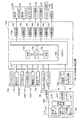
本液圧ブレーキ装置は、制御装置150によって制御される。図3に示すように、制御装置150は、CPU152,ROM154,RAM156,入出力部158等を有するコンピュータ159を主体とするものである。入出力部158には、上述のアキュムレータ圧センサ38,液圧センサ120に加えて、液通路44,46の液圧をそれぞれ検出するマスタ圧センサ160,162、ブレーキシリンダ18,19,26,27の液圧をそれぞれ検出するブレーキ圧センサ164〜167、各車輪16,17,24,25の車輪速度をそれぞれ検出する車輪速センサ169〜172、ブレーキペダル10に加えられる踏力を検出する踏力センサ174、ブレーキペダル10が操作状態にあるか否かを検出するブレーキスイッチ176、車両のヨーレイトを検出するヨーレイトセンサ178、車輪に加えられる前後力、上下力、横力をそれぞれ検出するタイヤ作用力検出装置180等が接続されている。また、ポンプモータ32、各リニアバルブ装置80〜86のコイル100、各電磁開閉弁50,52,58,60,68のコイルがそれぞれ駆動回路182を介して接続される。
なお、タイヤ作用力検出装置180は、前後力、横力、上下力をそれぞれ検出するものとする必要は必ずしもなく、少なくとも前後力を検出するものとすればよい。
【0018】
本液圧ブレーキ装置においては、踏力センサ174による出力信号に基づいて運転者の所望する要求制動力としての要求ブレーキ圧が求められる。また、要求ブレーキ圧は、マスタ圧センサ160,162による出力信号に基づいて求めることもできる。
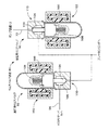
タイヤ作用力検出装置180は、本実施形態においては、車輪16,17,24,25にそれぞれ設けられ、車輪に加えられる前後力、上下力、横力をそれぞれ検出する。タイヤ作用力検出装置180は、図示を省略するが、タイヤを保持するホイールとアクスルハブとの間の回転体側に設けられた検出部200と、非回転体側に設けられた演算部202とを含み、これら検出部200と演算部202との間で通信が行われる。
検出部200は、前後力用歪みゲージ210,上下力用歪みゲージ212,横力用歪みゲージ213,信号処理部214,送信器216,電源としての電池(バッテリ)218等を含み、演算部202は、受信器220,信号処理部222等を含む。この作用力検出装置180については、特開2003−14563として公開された本出願人の出願明細書に詳細に説明されているため、ここでの詳細な説明は省略する。
【0019】
前後力用歪みセンサゲージ210,上下力用歪みゲージ212,横力用歪みゲージ213は、ホイールとアクスルハブとの間に設けられた検出体の、ホイールとアクスルハブとの相対移動に伴って変形させられる部分にそれぞれ設けられる。前後力用歪みゲージ210は、前後力に基づく相対移動に伴って変形させられる部分に取り付けられ、上下力用歪みゲージ212は、上下力に基づく相対移動に伴って変形させられる部分に取り付けられ、横力用歪みゲージ213は、横力に基づく相対移動に伴って変形させられる部分に取り付けられる。信号処理部214は、歪みゲージ210,212,213の電気信号を通信に適した信号(情報)に変換するものであり、送信器216はアンテナ等を含むものである。信号処理部214において処理された歪みを表す通信用情報は送信器216を経て非回転体側の演算部202に送信される。
【0020】
演算部202は、非回転体側の部材の、車輪に比較的近い位置に設けられる。演算部202においては、受信器220において検出部200から送信された情報が受信され、信号処理部222において、歪みに基づいて、前後力、上下力、横力が求められ、それを表す情報が制御装置150に供給される。回転体側に設けられた送信器216および非回転体側に設けられた受信器220等によって通信部224が構成される。
なお、歪みゲージは、ホイールに取り付けたり、アクスルハブに取り付けたりすることができる。また、車輪を保持する非回転部材であるサスペンションアームに取り付けることも可能であり、非回転部材に取り付ければ、情報を送信、受信するための通信部が不要となる。
【0021】
通常制動時には、マスタ遮断弁50,52が閉状態にされることによってブレーキシリンダ18,19,26,27がマスタシリンダ14から遮断される。また、連通弁58,60が閉状態にされ、シミュレータ用開閉弁68が開状態にされる。この状態において、ブレーキシリンダ18,19,26,27の液圧が、ポンプ装置12の作動液を利用して、リニアバルブ装置80〜86のコイル100への供給電流の制御によりそれぞれ制御される。ブレーキ圧が運転者の所望する要求ブレーキ圧に等しくなるように、リニアバルブ装置80〜86への供給電流が決定される。なお、マスタシリンダ14にはストロークシミュレータ67が連通させられるため、ブレーキペダル10のストロークが殆ど0になることを回避することができる。
【0022】
ポンプ装置12や電気系統に異常が生じた場合には、各電磁制御弁は図1に示す原位置に戻される。マスタ遮断弁50,52が開状態に、連通弁58,60が開状態にされるため、ブレーキシリンダ18,19,26,27がマスタシリンダ14に連通させられる。また、シミュレータ用開閉弁68が閉状態にされるため、ストロークシミュレータ66がマスタシリンダ42から遮断され、作動液が無駄に消費されることが回避される。さらに、リニアバルブ装置80〜86の各コイル100には電流が供給されなくなるため、増圧リニアバルブ90,減圧リニアバルブ92はいずれも閉状態にされる。ブレーキシリンダ18,19,26,27がポンプ装置12から遮断される。
【0023】
また、運転者が可能な限り大きな減速度で車両を減速することを要求している最大減速度要求が検出され、かつ、最大減速度制御が許可されていれば最大減速度制御が行われ、あるいは、車輪のスリップが過大となる傾向がある場合にはアンチロック制御が行われる。最大減速度制御中において、最大減速度制御を解除すべき状態となれば減速度制御が解除され、その時点でアンチロック制御が必要であれば、アンチロック制御が行われる。アンチロック制御は、車両が停止した場合、ブレーキペダル10の踏み込みが解除された場合等の予め定められた終了条件が満たされた場合に終了させられる。最大減速度制御においては、車両の減速度が可能な限り大きくなるように、ブレーキシリンダ18,19,26,27の液圧であるブレーキ圧が適正値に保持され、また、アンチロック制御においては、制動スリップ状態が適正状態に近づくように、ブレーキ圧が増圧されたり減圧されたりする。いずれにしても、ブレーキ圧はポンプ装置12の作動液を利用して、リニアバルブ装置80〜86のコイル100への供給電流の制御により制御される。
【0024】
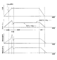
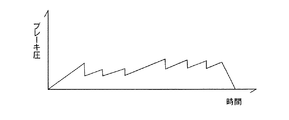
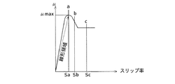
最大減速度制御は、最大減速度要求が検出された時点に走行中の路面と車輪との間に期待できる最大摩擦係数μmax(これが、通常、摩擦係数と称されているものであるが、本明細書においては、路面利用μ、すなわち制動のために実際に利用される摩擦係数との違いを明確にするために最大摩擦係数と称する)に応じて決まる最大減速度Gmaxで車両を減速するようにブレーキ圧を制御するものであり、Gmax制御と略称することとする。Gmax制御は、原則として、図4に示すように初期段階,中間段階および保持段階の3つの段階で実行される。初期段階は、上記最大摩擦係数μmaxを取得するまでの段階であり、中間段階は一旦ブレーキ圧を低下させる段階であり、保持段階は、ブレーキ圧を、初期段階において取得された最大摩擦係数μmaxに基づいて決まる保持ブレーキ圧まで増大させ、そのブレーキ圧を保持する段階である。Gmax制御の後に終了段階が実行されるのが普通であるが、場合によっては、図5に示すように途中からアンチロック制御に移行することや、図6に示すようにGmax制御は全く行われず、当初からアンチロック制御が実行されることもある。Gmax制御は、アンチロック制御の一種とも言い得るため、新アンチロック制御あるいは保持型アンチロック制御と称し、それとの比較において、車輪のスリップ状態を監視しつつブレーキ圧を増圧したり減圧したりして実際のスリップ状態を目標スリップ状態に近づけるアンチロック制御を従来型アンチロック制御と称することもできる。
【0025】
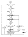
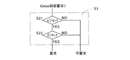
上記制御を行うために、制御装置150のROM154には図7ないし図10のフローチャートで表される制御プログラムが格納されている。イグニッションスイッチ等の車両メインスイッチがオン状態にされるのに応じて図示しない初期設定が実行された後、車両メインスイッチがオン状態にされている間、本制御プログラムが微小時間毎に繰り返し実行される。図7のステップ1(以下、S1と略記し、他のステップについても同様とする)において、ブレーキペダル10の踏込みが開始されてブレーキスイッチ176がオンとなることが待たれる。オンになれば、S2,S2aを経、S3においてGmax制御要求がなされているか否かが判定される。この判定は、例えば、制動操作部材の操作速度が設定操作速度より大きくかつ制動操作部材の操作力が設定操作力より大きいか否かにより行われる。本実施形態においては、図8に示すように、ブレーキペダル10の操作速度v(具体的には踏力センサ174の出力信号に基づいて取得される踏力fの変化速度であり、ここにおいては正の値として取得される)が正の設定操作速度V1より大きく(S21)かつ踏力f(常に正の値として取得される)が設定踏力F1より大きい(S22)場合にGmax制御要求がなされていると検出されるが、マスタ圧センサ160,162の出力信号に基づいて取得されるマスタ圧の変化勾配が正の設定変化勾配より大きくかつマスタ圧が正の設定マスタ圧より大きい場合にGmax制御要求がなされていると検出されるようにすることもできる。上記設定踏込速度(設定操作速度)V1は、例えば800N/sec以上の範囲あるいは400N/sec以上の範囲から選定され、設定踏力(設定操作力)F1は例えば80N以上の範囲あるいは160N以上の範囲から選定されるというように、それぞれ急ブレーキと称される範囲の下限値に設定される。なお、ブレーキペダル10の設定踏込速度と設定踏力とは、設定踏力が大きい場合には設定踏込速度が比較的小さくてもGmax制御要求領域にあるとされるように、互いに関連を以て設定されることが望ましく、その一例を図13に示す。100N,200N等が設定踏力、500N/secN/,1000N/sec等が設定踏込速度であり、斜線が施された領域がGmax制御要求領域である。図13においては、踏力が設定踏力100N以下である場合には、踏込速度のいかんを問わずGmax制御要求領域とはされないようになっているが、踏込速度が設定踏込速度1000N/secより大きい場合には、踏力のいかんを問わずGmax制御要求領域とされるようにすることも可能である。
【0026】
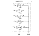
S3においてGmax制御の要求が検出されれば、S4においてGmax制御の開始が許容されているか否かが判定される。この判定は、例えば、運転者による運転操作の状態と、車両の走行状態と、路面の状態とに基づいて行われるようにすることができる。本実施形態においては、運転操作の一種としての操舵操作の状態と、車両の走行状態の一種としてのヨーレイトと、路面状態の一種としての路面摩擦係数μの左右差等に基づいて行われる。具体的には、図9に示すように、操舵角速度ωの絶対値が正の設定操舵角速度値Ω1より小さく(S31)、操舵角θの絶対値も正の設定操舵角値Θ1より小さい(S32)場合に、運転操作状態がGmax制御の開始を許容する状態にあると判定され、ヨーレイトγの絶対値が正の設定ヨーレイト値Γ1より小さくかつヨーレイトの変化速度γ´の絶対値が設定ヨーレイト変化速度値Γ1´より小さい場合に車両の走行状態がGmax制御の開始を許容する状態にあると判定され、路面摩擦係数μの左右差Δμの絶対値が設定左右差値ΔΜ1より小さい場合に路面状態がGmax制御を許容する状態にあると判定されるのである。上記設定操舵角速度値Ω1は、例えば、15°/sec以下あるいは30°/sec以下というように小さい操舵角速度値の範囲から選定された値に設定されることが望ましく、実質的に保舵中であると言い得るほど小さい値に設定されることがさらに望ましい反面、上記設定操舵角値Θ1は、例えば、最大操舵角の50%以上あるいは70%以上というように、比較的大きい操舵角値の範囲から選定された値に設定されても差し支えない。設定左右差値ΔΜ1は、路面摩擦係数μの大きい方の10%以下あるいは20%以下というように比較的小さい値の範囲から選定された値に設定されることが望ましい。
【0027】
S4でGmax制御の開始を許容する状態にあると判定されれば、S5でフラグFBが立てられる(1とされる)ため、次回にはS3およびS4の判定がスキップされる。S5に続いて、S6でGmax制御を解除すべき状態であるか否かが判定される。この判定は、本実施形態においては、運転操作状態,車両走行状態,路面状態がGmax制御の継続を許容する状態にあるか否か等に基づいて行われる。具体的には。図10に示すように、S41ないしS47の判定により行われるのであるが、S41,S42,S45,S46およびS47は図9におけるS31,S32,S33,S34およびS35とそれぞれ同様な判定である。ただし、判定の基準となる各設定値は図9におけるそれらと同じ値にしても、異なる値にしてもよい。S43およびS44はGmax制御を解除すべき状態であるか否かの判定に特有のものであり、S43においては踏力fが正の設定踏力F2より大きいか否かが判定される。設定踏力F2は前記図8における設定踏力F1より小さい値に設定され、ブレーキペダルが相当程度緩められたか否かが判定されることとなり、この判定は運転者がもはやGmax制御を要求しなくなったか否かの判定であると考えることもできる。S44はにおいてはブレーキペダル10の操作速度vの絶対値が設定操作速度値V2より小さいか否かが判定される。ブレーキペダル10が意図的に踏み増され、あるいは緩められたか否かが判定されるのである。この判定は運転操作状態の一種としての制動操作状態が定常状態にあるか否かの判定であると考えることもできる。
【0028】
S6の判定結果がYESであれば、S7でGmax制御の解除が行われるとともにフラグFBが倒され(0にされ)、NOであればS9でGmax制御が実行される。これらについては後に詳述する。
前記S3においてGmax制御が要求されていないと判定された場合、あるいはS4でGmax制御の開始を許容する状態にないと判定された場合には、S10でアンチロック制御を行うべきか否かが判定される。未だアンチロック制御が行われていない状態でS10が実行される場合には、アンチロック制御開始条件が満たされたか否かが、また、既にアンチロック制御が行われていれば、アンチロック制御終了条件が満たされたか否かが判定されるのであるが、従来公知のそれらと同様であるため詳細な説明は省略する。そして、アンチロック制御を行うべきである場合にはS11でフラグFAが立てられるとともに、S8においてアンチロック制御が行われる。それに対し、アンチロック制御を行う必要がない場合には、S12でフラグFAが倒されるとともに、S13において通常制御が行われる。通常制御は、ブレーキ圧をブレーキペダル10の踏力に対応する大きさに制御するものであり、ブレーキペダル10の踏込開始当初、すなわちS1の判定がYESとなって短時間の間は、S2,S3,S4およびS10の判定結果がNOとなるため、S13の通常制御が必ず行われる。また、S11でフラグFAが立てられれば、S2の判定結果がYESとなって、S2a以下のGmax制御に関するステップがスキップされ、S8のアンチロック制御が実行されるため、アンチロック制御が先に開始された場合にはもはやGmax制御は行われない。
【0029】
次に、S9のGmax制御の詳細を説明する。Gmax制御は、制御パラメータとしてのスリップ状態関連量としての前後力分担関連量に基づいて行われる。前後力分担関連量が最大路面利用μ対応前後力分担関連量に保たれるようにブレーキ圧が制御されるのである。また、本実施形態においては、すべての車輪において路面利用μが最大となるように制御される。そのため、車両全体の前後力をその時点に車両が走行している路面上において期待できるうちでは最大の前後力とすることができ、最大の減速度が得られる。停車時には最短の停止距離が得られるのであり、Gmax制御は、μmax制御、停止距離最短制御と称することもできる。この制御は前述のように、初期段階,中間段階および保持段階の3つの段階で実行される。初期段階は、最大摩擦係数μmaxを取得するまでの段階であり、最大摩擦係数μmaxの取得は以下の原理で行われる。
【0030】
前後力分担関連量は、前後力に基づいて求められた車体速度関連量と車輪速度関連量とに基づいて取得される。車輪速度関連量と車体速度関連量とに基づけば、その車輪の分担する車両における前後力の割合に関連する量を取得することができる。また、前後力分担関連量によれば、車輪のスリップ状態を推定することができる。この意味において、前後力分担関連量を推定スリップ状態関連量と称することもできる。
本実施形態においては、前後力分担関連量としての制動力分担関連量Sが、車体速度関連量としての車体加速度をGvとし、車輪速度関連量としての車輪加速度をGwとした場合に、式
S=1−Gw/Gv
で表される値とされる。
【0031】
図11に示すように、スリップ率が小さく、スリップ率の増加に伴って路面利用μが比例的に増加する線形領域においては、ブレーキ圧の増加に伴って路面摩擦力が増加する。路面利用μは、路面とタイヤとの間の最大摩擦係数μmaxまで増加するがそれ以上増加することはない。
路面利用μが最大である場合に摩擦力が最大になるが、車体減速度は車体加速度と符号が正負逆のものであって、車両全体の摩擦力(すべての車輪の摩擦力の合計)が最大の場合に最大になる。この時の制動力分担関連量が最大路面利用μ対応制動力分担関連量である。本実施形態においては、路面の最大摩擦係数μmaxが均一である限りすべての車輪の摩擦力が同時に最大になるようにブレーキ20,21,28,29が設計されており、すべての車輪について同じ勾配でブレーキ圧が増加させられる。
ブレーキ圧がさらに増加すると、摩擦力はそれ以上大きくなることはないが、車輪減速度が大きくなるため、スリップ率が過大になり、ロック傾向が強くなる。この領域はスリップ率の増加に伴って路面利用μが比例的に大きくなることがない非線形領域である。
【0032】
制動力分担関連量Sは、図12の実線で表され、負の値である。図に示すように、スリップ率と同じ大きさになるわけではないが、図11と比較すれば明らかなように、前後力分担関連量によれば、ロック傾向が強いか否か等を推定することができる。制動スリップの増加傾向においては、車輪減速度(車輪減速度は車輪加速度と符号が正負逆のものである)が車体減速度に対して大きくなるため負の値になるのである。
図11に示す線形領域において、車輪減速度が車体減速度の増加に伴って増加するため、図12に示すように、制動力分担関連量Sの絶対値は、車体減速度の増加に伴って僅かに増加するかほぼ一定に保たれる。ただし、制動当初の車体減速度が小さい領域においては、車輪減速度の増加勾配が車体減速度の増加勾配に対して大きいため、制動力分担関連量の絶対値が漸増する。制動初期には、車輪減速度Gwの方が車体減速度Gvより増加勾配が大きいが、その後、これらは比例的に増加するのである。
このように、この制動スリップが小さい線形領域においては、制動力分担関連量の絶対値が大きいほど、その車輪の分担割合が大きいと考えられる。また、制動力分担関連量の絶対値が小さく、変化勾配が小さい場合は制動スリップが小さい線形領域にあると考えることができる。
【0033】
また、車体減速度はすべての車輪についての路面と車輪との間の摩擦力の和に応じた大きさであり、各々の車輪の摩擦力は路面とその車輪との間の最大摩擦係数μmaxに対応する大きさより大きくなることはない。車体減速度は、複数の車輪の摩擦力の合計が最大になった場合に最大となる。
すなわち、すべての車輪についての路面の最大摩擦係数μmaxが同じ場合において、各々の車輪のブレーキ作動力を制御することにより、すべての車輪についての摩擦力が同時に最大となるようにされる場合には、制動力分担関連量は図12の実線(車両によって決まる予め定められ関係を保った状態)に従って変化し、摩擦力が最大になった時の値がaになる。制動力分担関連量がaになった場合には、複数の車輪の各々の分担割合は予め決まった値となる。
その後、ブレーキ作動力が増加しても摩擦力、すなわち、車体減速度が大きくなることがないのに対して、車輪減速度は大きくなる。制動スリップが急に大きくなり、ロック傾向が強くなる。一方、車体減速度は減少に転じ、制動力分担関連量Sの絶対値が急激に大きくなる(b〜c)。
【0034】
それに対して、複数の車輪のうちの1輪について路面の最大摩擦係数μmaxが小さい場合に、すべての車輪のブレーキ作動力が路面の最大摩擦係数μmaxが均一である場合と同様に増加させられれば、その車輪の制動力分担関連量Sの絶対値は2点鎖線に示すように増加する。他の車輪についての摩擦力が増加傾向にあるため、車体減速度は増加するが、その1輪については、車体減速度の増加に比較して車輪減速度の増加が大きくなるため、制動力分担関連量Sの絶対値が通常の場合(路面の最大摩擦係数μmaxが均一である場合)に比較して急速に増加するのである。
この場合には、車体減速度が最大になる以前であっても、制動力分担関連量Sの絶対値の増加勾配が他の車輪の増加勾配より大きくなれば、その車輪についての制動分担割合が小さくなり始めたことがわかる。また、その車輪のスリップ状態が他の車輪よりロック状態に近い状態にあることがわかるのである。
【0035】
このように、制動力分担関連量Sの絶対値が大きい場合は小さい場合よりその車輪のロック傾向が強いことがわかる。制動力分担関連量Sによれば、車輪のスリップの状態を推定することができるのであり、スリップ状態関連量の一態様であるとすることができる。
また、制動力分担関連量Sは、制動力が路面の最大摩擦係数μmaxとの関係において過大になる前と後とでは変化状態が大きく異なる量である。例えば、最大摩擦係数μmaxが均一である状態において、すべての車輪についての摩擦力が同時に最大となるように各車輪のブレーキ作動力が制御される場合には、車体減速度が最大になる前と後とにおいて変化状態が大きく異なるのである。最大になる以前においては、車体減速度の増加に伴って緩やかにその絶対値が増加し、最大になった後においては、車体減速度が減少に転じ、絶対値の増加勾配が大きくなるのである。また、一部の車輪に対応する路面の最大摩擦係数μmaxが他の車輪に対応する路面の最大摩擦係数μmaxに比較して明瞭に小さい場合に、すべての車輪についての摩擦力が同時に最大となるように各車輪のブレーキ作動力が制御される場合には、一部の車輪の制動力分担関連量Sの絶対値が、他の車輪のそれに比較して明らかに急速に増大する。そのため、制動力分担関連量によれば、車体減速度が最大になった時点や、制動力が最大摩擦係数μmaxとの関係において過大になった時点等を精度よく検出することができ、スリップ状態を精度よく推定することができるのであり、制動力分担関連量Sは前後力の制御に適しているといえる。
【0036】
車体加速度は、車両全体に加えられる前後力(総前後力)を車両全体に加えられる上下力(総上下力)で割ることによって取得することができる。総前後力Fsxは、各輪毎の前後力Fxiの和とすることができる。
Fsx=ΣFxi=FxfL+FxfR+FxrL+FxrR
車両全体に加えられる上下力(総上下力)Fszは、各輪に加えられる上下力Fziの和とすることができる。また、この総上下力は車両重量W(=M・g ただし、Mは車両質量)でもある。
Fsz=ΣFzi=FzfL+FzfR+FzrL+FzrR
したがって、車体加速度Gvは、重力加速度をgとした場合に、式
Gv=(Fsx/Fsz)・g
に従って求めることができる。
【0037】
このように、本実施形態においては、スリップ状態量としての前後力分担関連量Sが、前後力と上下力と車輪加速度とに基づいて求められるのであり、車輪速度に基づいて推定される車体速度に基づいて求められるわけではない。そのため、各車輪の前後力分担関連量を精度よく取得することができる。
なお、車両重量W(=M・g)は、車種で決まる車体重量、または、その車体重量と人間の標準体重に標準乗車人数を掛けた値とを加えた値とすることができる。車体重量に対して人間の重量は小さいからである。
また、車両重量Wは、前後Gセンサを設け、直進加速中等外乱が小さい状態における総前後力Fsxと前後Gセンサによって検出された車体加速度Gvとに基づいて取得することもできる。
W=(Fsx/Gv)・g
前後Gセンサは、普通、慣性を利用して車体加速度を検出するものであり、例えば、慣性に起因するマスの変位に基づいて検出するものである。そのため、外乱の影響を受けやすい。それに対して、直進制動中または直進駆動中であれば、外乱の影響を小さくすることができる。
【0038】
車体加速度は、さらに、荷重移動量に起因するモーメントに基づいて取得することもできる。前輪の上下力の変化量をΔFzfとし、ホイールベース、重心の高さをそれぞれL、Hとし、車両の重量(総上下力)Fszとした場合、前輪への荷重移動量に起因するモーメントと制動または駆動に応じたモーメントとが等しいとすることができるため、式
ΔFzf・L=Gv・Fsz・H
が成立する。ここで、左辺は、前輪の上下力の変化量と後輪の上下力の変化量とは符号が逆になるため、ホイールベースを掛ければよいのである。すなわち、左辺は、後輪の上下力の変化量ΔFzrにホイールベースを掛けた値とすることもできる。
また、車体加速度は、各車輪毎における前後力を上下力で割った値で近似することもできる。
Gv≒Fxi/Fzi
【0039】
Gmax制御の前記初期段階は、上記のように路面利用μが最大となる場合の前後力分担関連量である最大路面利用μ対応前後力分担関連量Sμmaxを求める段階である。前述のように、すべての車輪のブレーキ圧が一定の勾配で増加させられる場合において、前後力分担関連量の絶対値の増加勾配が急激に大きくなった時点の前後力分担関連量または増加勾配が急激に大きくなった時点からわずかに絶対値が増加した時点の値が最大路面利用μ対応前後力分担関連量Sμmaxとされるのである。そして、各車輪について最大路面利用μ対応前後力分担関連量Sμmaxが取得された時点のブレーキ圧が、ブレーキ圧センサ164,165,166,167の出力信号に基づいて取得され、各車輪と対応付けてRAM156に記憶される。この記憶されるブレーキ圧は、図11におけるスリップ率Saにほぼ対応する最大路面利用μ対応ブレーキ圧である。
以上の説明から明らかなように、上記最大路面利用μ対応前後力分担関連量Sμmaxは、路面の最大摩擦係数μmaxに対応するものであるので、最大路面利用μ対応前後力分担関連量Sμmaxの取得は実質的に路面の最大摩擦係数μmaxの取得に相当する。
【0040】
本Gmax制御は、各ブレーキシリンダ18,19,26,27のブレーキ圧を、以上のようにして取得し、記憶した最大路面利用μ対応ブレーキ圧に保持することにより、車両を最大減速度で減速させることを基本とするものであるが、各車輪に対応するブレーキシリンダのブレーキ圧が、最大路面利用μ対応ブレーキ圧が取得された時点から直ちに保持されるようにしたのでは、保持されるブレーキ圧が最大路面利用μ対応ブレーキ圧より大きくなり、車輪のスリップが過大となることを避け得ない。そこで、本実施形態においては、図4に示すように、ブレーキ圧を予め設定されたパターンに従って減圧および保持した後、最大路面利用μ対応ブレーキ圧まで増圧する中間段階が実行され、その後、ブレーキ圧を保持する保持段階が実行されるようにされている。
【0041】
本実施形態においては、前述のように、S10においてアンチロック制御を行うべきであると判定される前に、S3およびS4の判定結果がYESとなり、Gmax制御の開始が許容された場合にのみGmax制御が実行されるようになっている。そして、S3の判定は、踏力fが設定踏力F1より大きいか否かの判定を含む。したがって、最大摩擦係数μmaxが小さい路面上における制動時には、S10のYES判定がS3のYES判定より先になることがあり、その場合にGmax制御が実行されないこととなる。
【0042】
以上の説明から明らかなように、本実施形態においては、踏力センサ174と、コンピュータ159のS3を実行する部分とにより最大減速度要求検出部が構成され、コンピュータ159のS2〜S7およびS9を実行する部分により最大減速度制御部が構成されている。また、コンピュータ159のS31およびS32を実行する部分により運転操作状態検出部、S33およびS34を実行する部分により車両走行状態検出部、S35を実行する部分により路面状態検出部がそれぞれ構成されている。また、コンピュータ159のS4を実行する部分により最大減速度制御開始許可部が、S6を実行する部分により最大減速度制御解除指令部がそれぞれ構成され、それら最大減速度制御開始許可部および最大減速度制御解除指令部により最大減速度制御許可部が構成されている。さらに、別の見方をすれば、コンピュータ159のS8およびS9を実行する部分によりアンチロック制御部、S31,S34,S35,S41,S44,S46,S47等を実行する部分により定常走行検出部、S2,S4,S6,S7,S10,S11等を実行する部分により制御モード変更部がそれぞれ構成されている。
【0043】
なお、最大摩擦係数μmax(あるいは最大路面利用μ対応前後力分担関連量Sμmax)は、ブレーキ圧と路面利用μとの関係に基づいて取得することもできる。路面利用μは、各車輪において、前後力を上下力で割ることによって求めることができる。そして、ブレーキ圧の増加に伴って路面利用μが増加しなくなった時点における路面利用μ(あるいは前後力分担関連量)が最大摩擦係数μmax(あるいは最大路面利用μ対応前後力分担関連量Sμmax)であり、その時点のブレーキ圧が各車輪と対応付けてRAM156に記憶されるようにすれば、そのブレーキ圧を保持段階における保持ブレーキ圧として使用することができる。また、ブレーキ圧と路面利用μとの関係に基づく最大摩擦係数μmaxの取得には、車体減速度GVが不要であるため、すべての車輪の最大摩擦係数μmaxを互いに独立に取得することができる。例えば、複数の車輪においてGmax制御が開始された後であっても、残り車輪の最大摩擦係数μmaxの取得が可能なのであり、Gmax制御を従来型のアンチロック制御と同様に利用することができるのである。また、最大摩擦係数μmaxが小さい路面上においてもGmax制御が実行されるようにすることもできる。ただし、一旦Gmax制御が開始された後に、運転操作状態,車両走行状態,路面状態の少なくとも1つが定常状態ではなくなれば、Gmax制御が解除され、従来型のアンチロック制御に移行されるようにすることが望ましい。なお、Gmax制御が解除された場合に、従来型のアンチロック制御に移行されるようにすることは不可欠ではなく、通常制御が行われるようにすることも可能である。
【0044】
さらに、タイヤ作用力検出装置180を含むものとすることも不可欠ではない。要するに、最大摩擦係数μmaxあるいはそれに対応するブレーキ圧を取得することができればよいのである。例えば、ブレーキ圧等タイヤ前後力関連量(タイヤ前後力自体あるいはそれの演算を可能にする量)と、車体減速度,車体横加速度やサスペンションストローク等タイヤ上下力関連量(タイヤ上下力自体あるいはそれの演算を可能にする量)とに基づけば、最大摩擦係数μmaxを取得することができ、あるいは、スリップ率が設定値に達した際のブレーキ圧を取得し、それに設定係数を乗じて保持ブレーキ圧とすることも可能である。
【0045】
以上、本発明のいくつかの実施形態を詳細に説明したが、これらは例示に過ぎず、本発明は、前記〔発明が解決しようとする課題,課題解決手段および効果〕の項に記載された態様を始めとして、当業者の知識に基づいて種々の変更、改良を施した形態で実施することができる。
【図面の簡単な説明】
【図1】本発明の一実施形態であるブレーキシステムの回路図である。
【図2】上記ブレーキシステムの構成要素である増圧用リニヤバルブおよび減圧用リニヤバルブを概念的に示す図である。
【図3】上記ブレーキシステムの制御装置を示すブロック図である。
【図4】上記ブレーキシステムの作動を説明するためのグラフである。
【図5】上記ブレーキシステムの別の作動を説明するためのグラフである。
【図6】上記ブレーキシステムのさらに別の作動を説明するためのグラフである。
【図7】上記ブレーキシステムの制御プログラムを表すフローチャートである。
【図8】上記フローチャートの一部の詳細を示すフローチャートである。
【図9】図7のフローチャートの別の一部の詳細を示すフローチャートである。
【図10】図7のフローチャートのさらに別の一部の詳細を示すフローチャートである。
【図11】前記ブレーキシステムにおける最大摩擦係数の取得を説明するためのグラフである。
【図12】前記ブレーキシステムにおける最大摩擦係数の取得を説明するための別のグラフである。
【図13】前記ブレーキシステムにおける最大減速度制御(Gmax制御)要求領域の設定の一例を示すグラフである。
【符号の説明】
10:ブレーキペダル 12:ポンプ装置 14:マスタシリンダ 16:左前輪 17:右前輪 18,19:ブレーキシリンダ 20,21:ブレーキ 24:左後輪 25:右後輪 26,27:ブレーキシリンダ28,29:ブレーキ 38:アキュムレータ圧センサ 50,52:マスタ遮断弁 54,56:連通路 58,60:連通弁 66:シミュレーション装置 80,82,84,86:リニヤバルブ装置 90:増圧用リニヤバルブ 92:減圧用リニヤバルブ 120:液圧センサ 150:制御装置 160,162:マスタ圧センサ 164,165,166,167:ブレーキ圧センサ 169,170,171,172:車輪速センサ 174:踏力センサ 176:ブレーキスイッチ 180:タイヤ作用力検出装置[0001]
BACKGROUND OF THE INVENTION
The present invention relates to a brake system for a vehicle, and more particularly, to a brake system that can decelerate a vehicle with as large a deceleration as possible by preventing excessive slip of wheels during braking.
[0002]
[Prior art]
[0003]
[Patent Document 1]
JP-A-5-39021
[Patent Document 2]
JP-A-5-85327
[Patent Document 3]
JP 2003-14563 A
[Patent Document 4]
JP 2001-88576 A
[Patent Document 5]
JP-A-10-297450
[0004]
According to the brake system provided with the anti-lock control unit, the vehicle can be stopped at a short distance in comparison with the case where the anti-lock control unit is not provided. If the braking force that suppresses the wheel rotation is excessive in relation to the friction coefficient of the road surface (strictly, the maximum friction coefficient that can be expected between the tire and the road surface), the slip of the wheel is excessive. Thus, the actual frictional force between the wheel and the road surface decreases, and the distance required to stop the vehicle becomes long. However, if the brake system has an anti-lock control unit, the disadvantage is Can be avoided. For example, the anti-lock control unit decreases the brake operating force when the slip ratio is equal to or higher than the set slip ratio, and as a result, increases the brake operating force when a predetermined slip recovery tendency occurs. This is because it is possible to prevent the slip from becoming excessive by increasing / decreasing the brake operating force in accordance with the change.
[0005]
[Problems to be solved by the invention, means for solving problems and effects]
However, since the conventional anti-lock control unit increases or decreases the brake operating force as described above, it cannot be avoided that there is a time when the brake operating force is slightly inappropriate. There was a sway that the distance required to stop the vehicle would be longer. The present invention, against the background of the above circumstances, can use the friction coefficient of the road surface more effectively by the anti-lock control unit, that is, the maximum friction coefficient that can be expected between the tire and the road surface, and the distance necessary to stop the vehicle The present invention has been made to obtain a brake system that can further shorten the vehicle speed. According to the present invention, (1) a brake that suppresses the rotation of the wheel, and (2) the driver decelerates the vehicle with as large a deceleration as possible. A maximum deceleration request detection unit that detects the maximum deceleration request, and (3) at least when the maximum deceleration request is detected by the maximum deceleration request detection unit, A maximum deceleration control unit that performs a maximum deceleration control that maintains a magnitude that can be obtained, and the maximum deceleration control unit includes: (a) a road surface and wheels that are running when the maximum deceleration request is detected; of Holding brake actuation force is the operating force of the brake corresponding to the maximum coefficient of friction can be expected toHolding brake actuation force by increasing the brake actuation force until(B) an intermediate stage in which the brake operating force is temporarily reduced to a brake operating force smaller than the holding brake operating force following the initial stage, and (c) a brake operation following the intermediate stage. The brake is characterized in that after the power is increased to the holding brake operating force, a holding step of holding the holding brake operating force without increasing / decreasing the brake operating force is performed until the release condition of the maximum deceleration control is satisfied. A system is obtained.
In this way, if the holding brake operating force obtained in the initial stage and obtained at the initial stage is held at the holding brake operating force that can obtain the maximum deceleration without increasing / decreasing the brake operating force in the holding stage, braking is being performed as in the conventional antilock control. There is no longer a period when the brake operating force is slightly inappropriate, and the maximum friction coefficient that can be expected between the tire and the road surface can be used continuously, which is necessary to stop the vehicle. The effect of further shortening the distance can be obtained.
[0006]
According to the present invention, the brake system of the following aspects is further obtained. As with the claims, each aspect is divided into sections, each section is numbered, and is described in a form that cites the numbers of other sections as necessary. This is for the purpose of facilitating understanding of the present invention, and should not be construed as limiting the technical features described in the present specification and the combinations thereof to those described in the following sections. . In addition, when a plurality of items are described in one section, it is not always necessary to employ the plurality of items together. It is also possible to select and employ only some items.
[0007]
(1) a brake that suppresses rotation of the wheel;
A maximum deceleration request detector that detects a maximum deceleration request that requires the driver to decelerate the vehicle with as much deceleration as possible;
At least a maximum deceleration control unit that performs maximum deceleration control that maintains the operating force of the brake at a magnitude that provides the maximum deceleration when the maximum deceleration request is detected by the maximum deceleration request detection unit. When
A brake system comprising:
The maximum deceleration control unit holds the brake operating force at a level that allows the maximum deceleration to be obtained at least when the maximum deceleration request detection unit detects the driver's maximum deceleration request. Unlike the conventional anti-lock control unit, the brake operating force is not increased or decreased according to the fluctuation of the slip ratio of the wheel, but is maintained at an appropriate value, so that the maximum deceleration can be stably obtained. The distance required to decrease from a certain traveling speed to a desired traveling speed (including 0) can be minimized.
(2) The maximum deceleration request detection unit detects the maximum deceleration request when at least an operation force of the braking operation member by the driver is larger than a set braking operation force. Brake system.
The operation force of the braking operation member is positive for the direction in which the brake is applied. When the operating force is large, it is reasonable to consider that the driver is requesting that the vehicle be decelerated at maximum deceleration.
(3) The maximum deceleration request detection unit detects the maximum deceleration request when at least the operation speed of the braking operation member by the driver is greater than a positive set braking operation speed. Brake system according to item (2).
The operation speed of the braking operation member is positive in the direction in which the brake is applied. When the operation speed is high, the driver often requests that the vehicle be decelerated at the maximum deceleration. Therefore, it is appropriate to detect the maximum deceleration request based on the operation speed. Since the operation speed of the brake member generally decreases as the operation force increases, the set brake operation speed can be set to a constant value. However, the operation speed of the brake operation member is a region where the operation force is large. In this case, since it is usually smaller than a small region, it is desirable to set a smaller value when the operation force is large than when it is small. In this case, the set braking operation speed may be changed continuously or stepwise.
(4) It includes at least one of a driving operation state detection unit, a vehicle travel state detection unit, and a road surface state detection unit, and permits at least one of the maximum deceleration control when at least one of them detects the maximum deceleration control permission state. A maximum deceleration control permission unit is included, and when the maximum deceleration control permission unit permits the maximum deceleration control, the maximum deceleration control unit performs the maximum deceleration control (1) to ( Brake system according to item 3).
As will be described later, the brake system includes an anti-lock control unit together with a maximum deceleration control unit. When the slip of the wheel becomes excessive in the control by the maximum deceleration control unit, the operation of the maximum deceleration control unit is stopped. If the anti-lock control unit can be operated, the maximum deceleration control unit, for example, by maintaining the brake operating force at a size suitable for the dry asphalt road A braking system capable of obtaining the maximum deceleration on the dry asphalt road is obtained, and the maximum deceleration control permission unit is not essential. However, if the maximum deceleration control permission unit is provided, a brake system in which the maximum deceleration control unit operates only at an appropriate time can be obtained. At least the driving operation state, the vehicle traveling state, the road surface state, etc. are in the steady state as conditions for the driving operation state detecting unit, the vehicle traveling state detecting unit, the road surface state detecting unit, etc. to detect the maximum deceleration control allowable state. It is desirable that it be included. In principle, it is desirable that the maximum deceleration control be executed in a steady state.
(5) At least the driving operation state detection unit detects the maximum deceleration control permission state at least when the absolute value of the steering speed by the driver is smaller than the positive set steering speed. The brake system described.
When the absolute value of the steering speed is smaller than the positive set steering speed, it can be considered that the steering operation by the driver is in a steady state. The steering angle and the steering speed are usually positive and negative when the steering member such as a steering wheel is operated to the right and when it is operated to the left. Even when the vehicle is steered in the same direction, it can be handled in the same manner.
(6) The brake system according to (5), wherein at least the driving operation state detection unit detects the maximum deceleration control permission state at least when steering is performed by the driver.
(7) At least when the driving operation state detection unit detects that the absolute value of the steering angle is 80% or more of the maximum steering angle, the maximum deceleration control permission state is not detected. Brake system according to paragraph 4) to (6).
If it is detected that the absolute value of the steering angle is 80% or more of the maximum steering angle, it is desirable not to perform the maximum deceleration control even if the absolute value of the steering speed is small, It is further desirable not to be performed when it is detected that it is 50% or more.
(8) At least the driving operation state detection unit detects the maximum deceleration control permission state when at least the absolute value of the operation speed of the braking operation member by the driver is smaller than the positive set braking operation speed. The brake system according to any one of items (4) to (7).
When the absolute value of the operation speed of the braking operation member is small, it can be considered that the braking operation by the driver is in a steady state. The feature of this section is particularly effective when used to determine whether or not to cancel the maximum deceleration control, as will be described later in the section of the embodiment.
(9) At least when the vehicle running state detection unit detects that at least the absolute value of the lateral acceleration of the vehicle body is smaller than a positive set lateral acceleration, the maximum deceleration control permission state is detected. The brake system according to any one of items (4) to (8).
The sign of the lateral acceleration is reversed depending on the turning direction of the vehicle. In any case, if the absolute value of the lateral acceleration of the vehicle body is smaller than the positive set lateral acceleration, the vehicle running state detector can often decelerate at the maximum deceleration even if the vehicle is turning. It is reasonable to detect the maximum deceleration control allowable state.
(10) At least the vehicle running state detection unit detects the maximum deceleration control permission state at least when the absolute value of the change rate of the lateral acceleration of the vehicle body is smaller than a positive set change rate. The brake system according to any one of
When the change in the lateral acceleration is small, the vehicle running state can be considered to be in a steady state even during turning, so the vehicle running state detection unit detects the maximum deceleration control permission state. is there.
(11) At least the vehicle running state detection unit detects the maximum deceleration control permission state when at least the absolute value of the yaw rate of the vehicle body is smaller than the positive set yaw rate. (4) to (10) The brake system according to any one of the items.
The explanation in section (9) applies to this section.
(12) At least the vehicle running state detection unit detects the maximum deceleration control permission state when at least the absolute value of the change rate of the yaw rate of the vehicle body is smaller than a positive set change rate. Or the brake system according to any one of (11).
The explanation in section (10) applies to this section.
(13) At least the vehicle running state detection unit detects a maximum deceleration control allowable state at least when the absolute value of the rotational acceleration of the wheel is smaller than a positive set acceleration. The brake system according to any one of the paragraphs).
When the rotational acceleration of the wheel is greater than the positive set acceleration, the maximum deceleration control is canceled because it is highly possible that the operating force of the braking member has been reduced or the driving force of the drive source has been increased. It is desirable to do so. Even when the maximum friction coefficient of the road surface becomes large, the rotational acceleration of the wheel becomes larger than the positive set acceleration. In this case, it is not the vehicle running state detection unit but the road surface state detection unit. However, in any case, it is desirable that the maximum deceleration control is canceled. There is no inconvenience.
(14) At least the road surface state detection unit detects a friction coefficient left-right difference that is a difference between a friction coefficient of a road surface that is in contact with at least the left wheel and a friction coefficient of a road surface that is in contact with the right wheel. A difference detection unit is provided, and when the absolute value of the friction coefficient left / right difference is smaller than a positive set coefficient difference by the friction coefficient left / right difference detection unit, the maximum deceleration control permission state is detected (4). Or the brake system according to any one of (12).
When the difference in the friction coefficient (maximum friction coefficient) between the road surfaces in contact with the left and right wheels is large (referred to as a straddle road), it is not preferable to execute the maximum deceleration control.
(15) The friction coefficient left / right difference detecting unit includes at least an operating force difference detecting unit that detects a brake operating force difference between the left and right wheels, and an absolute value of the brake operating force difference detected by the operating force difference detecting unit is The brake system according to item (14), including means for detecting that the absolute value of the friction coefficient left-right difference is smaller than the positive set coefficient difference when the difference is smaller than the positive set operating force difference.
(16) The friction coefficient left-right difference detection unit includes at least a rotation speed difference detection unit that detects a difference in rotation speed between the left and right wheels, and an absolute value of the rotation speed difference detected by the rotation speed difference detection unit is positive. The brake system according to item (14) or (15), including means for detecting that the absolute value of the friction coefficient left-right difference is smaller than a positive setting coefficient difference when the difference is smaller than a set speed difference.
(17) The friction coefficient left-right difference detection unit is at least a difference between a ratio of the brake operation force-related amount of the left wheel and the wheel slip-related amount and a ratio of the brake operation force-related amount of the right wheel and the wheel slip-related amount. When the absolute value of the ratio difference detected by the ratio difference detection unit is smaller than the positive set ratio difference, the absolute value of the friction coefficient left-right difference is greater than the positive set coefficient difference. The brake system according to any one of (14) to (16), including means for detecting smallness.
The amount related to the brake operating force increases or decreases as the brake operating force increases or decreases, such as the brake operating force itself, the master pressure, and the tangential force with respect to the wheel (force perpendicular to the wheel rotation axis and in contact with the wheel). The amount corresponding to the wheel slip includes the amount that increases or decreases with the increase or decrease of the slip, such as the slip amount of the wheel, the slip rate, and the rotation deceleration. Although it is possible to detect a straddle based only on one of the brake actuation force-related quantity and the wheel slip-related quantity, the ratio of the left wheel brake actuation force-related quantity to the wheel slip-related quantity and the right wheel brake The detection reliability is higher when the detection is based on the difference between the ratio between the operating force related amount and the wheel slip related amount.
(18) In the state where the maximum deceleration control permission unit is not performing the maximum deceleration control, the maximum deceleration request is detected by the maximum deceleration request detection unit, and the driving operation state detection unit , Including a maximum deceleration control start permission unit that permits the start of the maximum deceleration control when the maximum deceleration control permission state is detected by at least one of the vehicle running state detection unit and the road surface state detection unit. (4) The brake system according to any one of
(19) The maximum deceleration control permission unit detects that the maximum deceleration request is not detected by the maximum deceleration request detection unit in a state where the maximum deceleration control is performed, and the driving operation state detection Maximum deceleration commanding the end of the maximum deceleration control when at least one of the maximum deceleration control permissible state is not detected by at least one of the vehicle section, the vehicle running state detection unit and the road surface state detection unit The brake system according to any one of (4) to (18), including a control end command section.
(20) An anti-lock control unit that prevents an excessive slip during braking of the wheel by controlling the operating force of the brake;
A selection unit for selecting the antilock control unit and the maximum deceleration control unit;
The brake system according to any one of (1) to (19).
Anti-lock control is also control that suppresses excessive slipping of the wheel, but because it increases or decreases the brake operating force while monitoring the slip state, the maximum reduction that keeps the brake operating force at the optimum level Compared to speed control, it is unavoidable that the deceleration of the vehicle becomes smaller. Therefore, the maximum deceleration control is a first slip control unit that controls to keep the wheel slip state in the first slip state, and the anti-lock unit has a second slip state in which the wheel slip is smaller than the first slip state. It can also be considered that the second slip control unit is controlled so as to be close to. In this case, the brake system includes at least one of a driving operation state detection unit, a vehicle traveling state detection unit, and a road surface state detection unit, and at least one of them detects the maximum deceleration control control permission state. It is desirable to include a selection unit that selects one slip control unit and selects the second slip control unit when the maximum deceleration control control allowable state is not detected.
(21) The brake system according to any one of (1) to (20), further including a holding brake operating force determining unit that determines a holding brake operating force that is the brake operating force to be held constant.
(22) a vertical force detection device that detects a vertical force that is a vertical force acting on the wheel;
A horizontal force detecting device for detecting a horizontal force which is a horizontal force acting on the wheel;
The brake according to item (21), wherein the holding brake operating force determination unit determines the holding brake operating force based on the vertical force and the horizontal force detected by the vertical force detection device and the horizontal force detection device. system.
Coefficient of friction
(23) The horizontal force detection device includes a tangential force detection device that detects, as the horizontal force, a tangential force that is a force perpendicular to a rotation axis of the wheel and in contact with the wheel as the horizontal force. The brake system described.
(24) A slip ratio detection device that detects a slip ratio of the wheel, the slip ratio detected by the slip ratio detection device, and the vertical force and horizontal detected by the vertical force detection device and the horizontal force detection device. The brake system according to any one of (21) to (23), wherein the holding brake operating force determining unit includes a slip ratio / horizontal force-based operating force determining unit that determines the holding brake operating force based on force.
(25) a brake for suppressing wheel rotation;
An anti-lock control unit that controls the braking force of the brake to avoid excessive slip during braking of the wheel; and
A steady running detection that includes at least one of a driving operation state detection unit, a vehicle running state detection unit, and a road surface state detection unit, and detects that the vehicle is in a steady running state when at least one of them detects a steady state. And
In the state where the steady running state is detected by the steady running detection unit, the antilock control unit is controlled to maintain the slip state of the wheel in the first slip state, and in the state where the steady running state is not detected. A control mode changing unit for controlling the wheel slip to be closer to a second slip state than the first slip state;
A brake system comprising:
The anti-lock control unit is changed in the control mode by the control mode changing unit, the first control mode for controlling the slip state of the wheel to be kept in the first slip state, and the second slip in which the wheel slip is smaller than the first slip state. It operates in the second control mode that controls to bring it closer to the state. The anti-lock control unit that operates in the first control mode includes the maximum deceleration control unit in the brake system according to the items (1) to (24).
(26) A maximum deceleration request detection unit that detects a maximum deceleration request that requires the driver to decelerate the vehicle at the maximum deceleration, and the maximum deceleration request detection unit detects the maximum deceleration request. And the control mode changing unit controls the anti-lock control unit to maintain the first slip state while the steady running detection unit is detecting the steady running state (25). Brake system.
[0008]
DETAILED DESCRIPTION OF THE INVENTION
Hereinafter, a brake system according to an embodiment of the present invention will be described in detail with reference to the drawings.
As shown in FIG. 1, the brake system includes a
The
[0009]
The
The
[0010]
The
[0011]
Master shut-off
The master shut-off
[0012]
A
[0013]
The
[0014]
As shown in FIG. 2, the pressure increasing
In the
In the state where no current is supplied to the
In a state where current is supplied to the
[0015]
The differential pressure acting force applied to the pressure increasing
[0016]
Further, a
[0017]
The hydraulic brake device is controlled by the
Note that the tire acting force detection device 180 is not necessarily required to detect the longitudinal force, the lateral force, and the vertical force, and may detect at least the longitudinal force.
[0018]
In the present hydraulic brake device, the required brake pressure as the required braking force desired by the driver is obtained based on the output signal from the
In this embodiment, the tire acting force detection device 180 is provided on each of the
The
[0019]
The longitudinal
[0020]
The
The strain gauge can be attached to a wheel or an axle hub. Moreover, it is also possible to attach to the suspension arm which is a non-rotating member which hold | maintains a wheel, and if it attaches to a non-rotating member, the communication part for transmitting and receiving information will become unnecessary.
[0021]
During normal braking, the
[0022]
When an abnormality occurs in the
[0023]
In addition, if the maximum deceleration request that requires the driver to decelerate the vehicle with the largest possible deceleration is detected, and the maximum deceleration control is permitted, the maximum deceleration control is performed, Alternatively, when there is a tendency for the wheel slip to become excessive, anti-lock control is performed. During the maximum deceleration control, the deceleration control is canceled if the maximum deceleration control is to be canceled, and if the antilock control is necessary at that time, the antilock control is performed. The anti-lock control is terminated when a predetermined termination condition such as when the vehicle stops or when the
[0024]
MostIn the large deceleration control, the maximum friction coefficient μmax that can be expected between the running road surface and the wheel when the maximum deceleration request is detected (this is usually referred to as the friction coefficient. In the specification, the vehicle is decelerated at a maximum deceleration Gmax determined according to the road surface utilization μ, that is, the maximum friction coefficient in order to clarify the difference from the friction coefficient actually used for braking. The brake pressure is controlled by Gmax control. In principle, the Gmax control is executed in three stages of an initial stage, an intermediate stage, and a holding stage as shown in FIG. The initial stage is a stage until the maximum friction coefficient μmax is obtained, the intermediate stage is a stage where the brake pressure is once reduced, and the holding stage is performed by setting the brake pressure to the maximum friction coefficient μmax obtained in the initial stage. This is a step of increasing the holding brake pressure determined based on the brake pressure and holding the brake pressure. Normally, the end stage is executed after the Gmax control. However, in some cases, the process proceeds to the anti-lock control as shown in FIG. 5, or the Gmax control is not performed at all as shown in FIG. In some cases, anti-lock control is executed from the beginning. Gmax control can be called a kind of anti-lock control, so it is called new anti-lock control or holding type anti-lock control. In comparison with that, the brake pressure is increased or decreased while monitoring the slip state of the wheel. The anti-lock control that brings the actual slip state closer to the target slip state can also be referred to as conventional anti-lock control.
[0025]
In order to perform the above control, the control program represented by the flowcharts of FIGS. 7 to 10 is stored in the
[0026]
If a request for Gmax control is detected in S3, it is determined in S4 whether the start of Gmax control is permitted. This determination can be made based on, for example, the state of the driving operation by the driver, the traveling state of the vehicle, and the road surface state. In the present embodiment, it is performed based on a steering operation state as a kind of driving operation, a yaw rate as a kind of vehicle running state, a left-right difference in a road surface friction coefficient μ as a kind of road surface condition, and the like. Specifically, as shown in FIG. 9, the absolute value of the steering angular velocity ω is a positive setting steering angular velocity value Ω.1Smaller (S31), the absolute value of the steering angle θ is also a positive setting steering angle value Θ1If it is smaller (S32), it is determined that the driving operation state is in a state allowing the start of Gmax control, and the absolute value of yaw rate γ is a positive set yaw rate value Γ.1The absolute value of the yaw rate change rate γ ′ is smaller than the set yaw rate change rate value Γ.1If it is smaller than ′, it is determined that the running state of the vehicle is in a state that allows the start of Gmax control, and the absolute value of the left-right difference Δμ of the road surface friction coefficient μ1If it is smaller, it is determined that the road surface condition is in a state allowing Gmax control. Above setting steering angular velocity value Ω1Is preferably set to a value selected from a range of small steering angular velocity values such as 15 ° / sec or less or 30 ° / sec or less, and is small enough to be said that the steering is substantially maintained. It is more desirable to set the value, but the set steering angle value Θ1May be set to a value selected from a relatively large range of steering angle values, such as 50% or more or 70% or more of the maximum steering angle. Set left / right difference value ΔΜ1Is preferably set to a value selected from a relatively small value range such as 10% or less or 20% or less of the larger road surface friction coefficient μ.
[0027]
If it is determined in S4 that the start of Gmax control is permitted, the flag FB is set (set to 1) in S5, so that the determination in S3 and S4 is skipped next time. Following S5, it is determined in S6 whether the Gmax control should be released. In this embodiment, this determination is made based on whether or not the driving operation state, the vehicle traveling state, and the road surface state are in a state that allows the Gmax control to be continued. In particular. As shown in FIG. 10, the determination is made in S41 to S47, but S41, S42, S45, S46 and S47 are the same determinations as S31, S32, S33, S34 and S35 in FIG. However, each set value that is a criterion for determination may be the same as or different from those in FIG. S43 and S44 are specific to the determination of whether or not the Gmax control should be released. In S43, the pedaling force f is a positive setting pedaling force F.2It is determined whether or not it is larger. Setting pedal force F2Is the set pedaling force F in FIG.1It is set to a smaller value and it is determined whether or not the brake pedal has been loosened considerably. This determination can be considered as a determination whether or not the driver no longer requires the Gmax control. In S44, the absolute value of the operation speed v of the
[0028]
If the determination result in S6 is YES, the Gmax control is canceled in S7 and the flag FB is turned down (set to 0). If NO, the Gmax control is executed in S9. These will be described in detail later.
If it is determined in S3 that Gmax control is not required, or if it is determined in S4 that the Gmax control is not allowed to start, it is determined whether or not antilock control should be performed in S10. Is done. When S10 is executed in a state where the antilock control has not yet been performed, whether or not the antilock control start condition has been satisfied, and if the antilock control has already been performed, the antilock control ends. Although it is determined whether or not the condition is satisfied, since it is the same as those conventionally known, detailed description is omitted. If antilock control is to be performed, a flag FA is set in S11 and antilock control is performed in S8. On the other hand, when it is not necessary to perform anti-lock control, the flag FA is turned down in S12, and normal control is performed in S13. In the normal control, the brake pressure is controlled to a magnitude corresponding to the depression force of the
[0029]
Next, details of the Gmax control in S9 will be described. The Gmax control is performed based on a longitudinal force sharing related amount as a slip state related amount as a control parameter. The brake pressure is controlled such that the front / rear force sharing-related amount is maintained at the maximum road surface use μ-compatible front / rear force sharing-related amount. In the present embodiment, the control is performed so that the road surface utilization μ is maximized for all the wheels. Therefore, the longitudinal force of the entire vehicle can be set to the maximum longitudinal force as long as it can be expected on the road surface on which the vehicle is traveling at that time, and the maximum deceleration can be obtained. Since the shortest stop distance is obtained when the vehicle is stopped, the Gmax control can also be referred to as μmax control or shortest stop distance control. As described above, this control is executed in three stages: an initial stage, an intermediate stage, and a holding stage. The initial stage is a stage until obtaining the maximum friction coefficient μmax, and obtaining the maximum friction coefficient μmax is performed according to the following principle.
[0030]
The front / rear force sharing-related amount is acquired based on the vehicle body speed-related amount and the wheel speed-related amount obtained based on the front / rear force. Based on the wheel speed related amount and the vehicle body speed related amount, it is possible to acquire the amount related to the ratio of the longitudinal force in the vehicle shared by the wheel. Further, according to the front / rear force sharing related amount, the slip state of the wheel can be estimated. In this sense, the front / rear force sharing-related amount can also be referred to as an estimated slip state-related amount.
In the present embodiment, when the braking force sharing related amount S as the front / rear force sharing related amount is Gv as the vehicle body acceleration as the vehicle speed related amount and the wheel acceleration as the wheel speed related amount is Gw,
S = 1-Gw / Gv
The value is represented by.
[0031]
As shown in FIG. 11, in a linear region where the slip ratio is small and the road surface utilization μ increases proportionally with an increase in the slip ratio, the road surface friction force increases with an increase in brake pressure. The road surface utilization μ increases up to the maximum friction coefficient μmax between the road surface and the tire, but does not increase any more.
The frictional force is maximized when the road surface utilization μ is maximum, but the vehicle body deceleration is the vehicle acceleration and the sign is the opposite of the sign, and the overall vehicle frictional force (the sum of the frictional forces of all wheels) is Maximum is maximum. The braking force sharing related amount at this time is the maximum road surface use μ corresponding braking force sharing related amount. In the present embodiment, the
As the brake pressure further increases, the frictional force does not increase any more, but the wheel deceleration increases, so the slip ratio becomes excessive and the tendency to lock increases. This region is a non-linear region where the road surface utilization μ does not increase proportionally with an increase in the slip ratio.
[0032]
The braking force sharing related amount S is represented by a solid line in FIG. 12, and is a negative value. As shown in the figure, it is not the same size as the slip ratio, but as is clear from the comparison with FIG. 11, it is estimated whether or not the locking tendency is strong, etc. be able to. In the increasing tendency of the braking slip, the wheel deceleration (the wheel deceleration is a sign that the sign of the wheel acceleration is opposite to the sign of the wheel acceleration) becomes larger than the vehicle body deceleration, and thus becomes a negative value.
In the linear region shown in FIG. 11, the wheel deceleration increases as the vehicle body deceleration increases. Therefore, as shown in FIG. 12, the absolute value of the braking force sharing related amount S increases as the vehicle body deceleration increases. Slightly increases or remains almost constant. However, in the region where the vehicle body deceleration at the beginning of braking is small, the absolute value of the braking force sharing related amount gradually increases because the increasing gradient of the wheel deceleration is larger than the increasing gradient of the vehicle body deceleration. In the initial stage of braking, the wheel deceleration Gw has a larger increasing gradient than the vehicle body deceleration Gv, but thereafter these increase proportionally.
Thus, in the linear region where the braking slip is small, it is considered that the larger the absolute value of the braking force sharing related amount, the larger the sharing ratio of the wheel. Further, when the absolute value of the braking force sharing related amount is small and the change gradient is small, it can be considered that the braking slip is in a linear region.
[0033]
The vehicle body deceleration is a magnitude corresponding to the sum of the friction forces between the road surface and the wheels for all wheels, and the friction force of each wheel is the maximum friction coefficient μmax between the road surface and the wheels. It cannot be larger than the corresponding size. The vehicle body deceleration becomes maximum when the sum of the frictional forces of a plurality of wheels becomes maximum.
That is, when the maximum friction coefficient μmax of the road surface for all the wheels is the same, the frictional force for all the wheels is maximized at the same time by controlling the brake operating force of each wheel. The braking force sharing related amount changes according to the solid line in FIG. 12 (a state in which a predetermined relationship determined by the vehicle is maintained), and the value when the frictional force becomes maximum is a. When the braking force sharing-related amount is a, the sharing ratio of each of the plurality of wheels is a predetermined value.
Thereafter, even if the brake actuation force increases, the frictional force, that is, the vehicle body deceleration does not increase, whereas the wheel deceleration increases. The braking slip suddenly increases and the locking tendency becomes stronger. On the other hand, the deceleration of the vehicle body starts to decrease, and the absolute value of the braking force sharing-related quantity S increases rapidly (b to c).
[0034]
On the other hand, if the maximum friction coefficient μmax of the road surface is small for one of the plurality of wheels, the brake operating force of all the wheels can be increased in the same manner as when the maximum friction coefficient μmax of the road surface is uniform. The absolute value of the braking force sharing related amount S of the wheel increases as shown by a two-dot chain line. Since the frictional force of other wheels tends to increase, the vehicle body deceleration increases. However, for one of the wheels, the increase in wheel deceleration is larger than the increase in vehicle body deceleration, so the braking force is shared. The absolute value of the related quantity S increases rapidly as compared with the normal case (when the maximum friction coefficient μmax of the road surface is uniform).
In this case, even before the vehicle body deceleration is maximized, if the increasing gradient of the absolute value of the braking force sharing-related quantity S is larger than the increasing gradient of the other wheels, the braking sharing ratio for that wheel is increased. You can see that it started to get smaller. It can also be seen that the slip state of the wheel is closer to the locked state than the other wheels.
[0035]
Thus, it can be seen that when the absolute value of the braking force sharing-related quantity S is large, the locking tendency of the wheel is stronger than when the absolute value is small. According to the braking force sharing-related amount S, the state of slipping of the wheel can be estimated, and can be regarded as one aspect of the slip state-related amount.
Further, the braking force sharing-related amount S is an amount in which the change state greatly differs before and after the braking force becomes excessive in relation to the maximum friction coefficient μmax of the road surface. For example, in the state where the maximum friction coefficient μmax is uniform, when the brake actuation force of each wheel is controlled so that the frictional force for all the wheels is maximized simultaneously, The change state is greatly different from the latter. Before reaching the maximum, the absolute value gradually increases as the vehicle body deceleration increases, and after reaching the maximum, the vehicle body deceleration starts to decrease and the gradient of increase in the absolute value increases. . In addition, when the maximum friction coefficient μmax of the road surface corresponding to some wheels is clearly smaller than the maximum friction coefficient μmax of the road surfaces corresponding to other wheels, the frictional force on all the wheels simultaneously becomes maximum. Thus, when the brake operating force of each wheel is controlled, the absolute value of the braking force sharing related amount S of some wheels obviously increases rapidly compared to that of the other wheels. Therefore, according to the braking force sharing related amount, it is possible to accurately detect when the vehicle body deceleration becomes maximum or when the braking force becomes excessive in relation to the maximum friction coefficient μmax, etc. Therefore, it can be said that the braking force sharing-related quantity S is suitable for controlling the longitudinal force.
[0036]
The vehicle body acceleration can be obtained by dividing the longitudinal force (total longitudinal force) applied to the entire vehicle by the vertical force (total vertical force) applied to the entire vehicle. The total longitudinal force Fsx can be the sum of the longitudinal force Fxi for each wheel.
Fsx = ΣFxi = FxfL + FxfR + FxrL + FxrR
The vertical force (total vertical force) Fsz applied to the entire vehicle can be the sum of the vertical force Fzi applied to each wheel. This total vertical force isVehicle weight W (= M · g, where M is the vehicle mass)But there is.
Fsz = ΣFzi = FzfL + FzfR + FzrL + FzrR
Therefore, the vehicle body acceleration Gv is expressed by the equation when the acceleration of gravity is g.
Gv = (Fsx / Fsz) · g
Can be asked according to.
[0037]
Thus, in the present embodiment, the front / rear force sharing-related amount S as the slip state amount is obtained based on the front / rear force, the vertical force, and the wheel acceleration, and is estimated based on the wheel speed. It is not required based on. Therefore, the front-rear force sharing related amount of each wheel can be obtained with high accuracy.
Vehicle weightW (= M · g)The vehicle body weight determined by the vehicle type, or a value obtained by adding the vehicle body weight and the standard human weight multiplied by the standard number of passengers. This is because the human weight is smaller than the vehicle weight.
Also vehicle weightWCan be obtained based on the total longitudinal force Fsx and the vehicle body acceleration Gv detected by the longitudinal G sensor in a state where the disturbance is small, such as during linear acceleration, by providing a longitudinal G sensor.
W =(Fsx / Gv) · g
The front-rear G sensor normally detects vehicle body acceleration using inertia, for example, based on displacement of mass due to inertia. Therefore, it is easily affected by disturbance. On the other hand, the influence of the disturbance can be reduced during the straight braking or the straight driving.
[0038]
The vehicle body acceleration can also be acquired based on the moment resulting from the load movement amount. When the amount of change in the vertical force of the front wheel is ΔFzf, the height of the wheelbase and the center of gravity is L and H, respectively, and the vehicle weight (total vertical force) Fsz, the moment and braking caused by the load movement amount to the front wheel Or the moment according to the drive can be equal, so the equation
ΔFzf · L = Gv · Fsz · H
Is established. Here, since the sign of the amount of change in the vertical force of the front wheel and the amount of change in the vertical force of the rear wheel is reversed, the left side may be multiplied by the wheel base. That is, the left side can be a value obtained by multiplying the change amount ΔFzr of the vertical force of the rear wheel by the wheel base.
The vehicle body acceleration can also be approximated by a value obtained by dividing the longitudinal force for each wheel by the vertical force.
Gv ≒ Fxi / Fzi
[0039]
The initial stage of Gmax control is a step of obtaining a maximum road surface utilization μ-related longitudinal force sharing related amount Sμmax, which is a longitudinal force distribution related amount when the road surface utilization μ is maximized as described above. As described above, when the brake pressure of all the wheels is increased at a constant gradient, the longitudinal force sharing related amount or the increasing gradient at the time when the increasing gradient of the absolute value of the longitudinal force sharing related amount suddenly increases is obtained. The value at the time when the absolute value slightly increases from the time when it suddenly increases becomes the maximum road surface use μ corresponding front / rear force sharing related amount Sμmax. Then, the brake pressure at the time when the maximum road surface use μ corresponding front-rear force sharing related amount Sμmax is acquired for each wheel is acquired based on the output signals of the
As is clear from the above description, the maximum road surface use μ-related front / rear force sharing related amount Sμmax corresponds to the road surface maximum friction coefficient μmax, and therefore the maximum road surface use μ-compatible front / rear force distribution related amount Sμmax is obtained. Substantially corresponds to obtaining the maximum friction coefficient μmax of the road surface.
[0040]
In this Gmax control, the brake pressure of each
[0041]
In this embodiment, as described above, only when the determination result of S3 and S4 is YES and the start of Gmax control is permitted before it is determined that the antilock control should be performed in S10, Gmax is permitted. Control is to be executed. In S3, the pedaling force f is set to the set pedaling force F.1Includes determining if greater than. Accordingly, when braking on a road surface having a small maximum friction coefficient μmax, the YES determination in S10 may precede the YES determination in S3, and in this case, Gmax control is not executed.
[0042]
As is apparent from the above description, in the present embodiment, the maximum deceleration request detection unit is configured by the
[0043]
It should be noted that the maximum friction coefficient μmax (or the maximum road surface use μ corresponding front-rear force sharing related amount Sμmax) can also be acquired based on the relationship between the brake pressure and the road surface use μ. The road surface utilization μ can be obtained by dividing the longitudinal force by the vertical force at each wheel. The road surface utilization μ (or the front / rear force sharing related amount) when the road surface utilization μ does not increase with the increase of the brake pressure is the maximum friction coefficient μmax (or the maximum road surface utilization μ corresponding front / rear force sharing related amount Sμmax). If the brake pressure at that time is stored in the
[0044]
Further, it is not essential to include the tire acting force detection device 180. In short, it is only necessary to obtain the maximum friction coefficient μmax or the corresponding brake pressure. For example, the tire longitudinal force related amount such as brake pressure (the tire longitudinal force itself or an amount capable of calculation thereof) and the tire vertical force related amount such as vehicle deceleration, vehicle lateral acceleration and suspension stroke (tire vertical force itself or it) The maximum friction coefficient μmax can be obtained, or the brake pressure when the slip ratio reaches the set value can be obtained and multiplied by the set coefficient to hold brake. It is also possible to use pressure.
[0045]
As mentioned above, although some embodiment of this invention was described in detail, these are only illustrations and this invention was described in the above-mentioned section of [the subject which invention intends to solve, a problem-solving means, and an effect]. The present invention can be implemented in various forms including various modifications and improvements based on the knowledge of those skilled in the art.
[Brief description of the drawings]
FIG. 1 is a circuit diagram of a brake system according to an embodiment of the present invention.
FIG. 2 is a diagram conceptually showing a pressure increasing linear valve and a pressure reducing linear valve, which are components of the brake system.
FIG. 3 is a block diagram showing a control device of the brake system.
FIG. 4 is a graph for explaining the operation of the brake system.
FIG. 5 is a graph for explaining another operation of the brake system.
FIG. 6 is a graph for explaining still another operation of the brake system.
FIG. 7 is a flowchart showing a control program of the brake system.
FIG. 8 is a flowchart showing details of a part of the flowchart.
FIG. 9 is a flowchart showing details of another part of the flowchart of FIG. 7;
FIG. 10 is a flowchart showing details of still another part of the flowchart of FIG. 7;
FIG. 11 is a graph for explaining acquisition of a maximum friction coefficient in the brake system.
FIG. 12 is another graph for explaining the acquisition of the maximum friction coefficient in the brake system.
FIG. 13 is a graph showing an example of setting of a maximum deceleration control (Gmax control) request area in the brake system.
[Explanation of symbols]
10: Brake pedal 12: Pump device 14: Master cylinder 16: Front left wheel 17: Right
Claims (8)
運転者ができる限り大きな減速度で車両を減速させることを要求する最大減速度要求を検出する最大減速度要求検出部と、
少なくとも、前記最大減速度要求検出部により前記最大減速度要求が検出された場合に、前記ブレーキの作動力を最大減速度が得られる大きさに保持する最大減速度制御を行う最大減速度制御部と
を含み、前記最大減速度制御部が、(a)最大減速度要求が検出された時点に走行中の路面と車輪との間に期待できる最大摩擦係数に対応する前記ブレーキの作動力である保持ブレーキ作動力が取得できるまで前記ブレーキの作動力を増大させて保持ブレーキ作動力を取得する初期段階と、(b)その初期段階に続いて前記ブレーキの作動力を一旦前記保持ブレーキ作動力より小さいブレーキ作動力まで減少させる中間段階と、(c)その中間段階に続いて前記ブレーキの作動力を前記保持ブレーキ作動力まで増大させた後、前記最大減速制御の解除条件が成立するまで前記ブレーキの作動力を増減させることなく前記保持ブレーキ作動力に保持する保持段階とを実行することを特徴とするブレーキシステム。A brake that suppresses the rotation of the wheels,
A maximum deceleration request detector that detects a maximum deceleration request that requires the driver to decelerate the vehicle with as much deceleration as possible;
At least a maximum deceleration control unit that performs maximum deceleration control that maintains the operating force of the brake at a magnitude that provides the maximum deceleration when the maximum deceleration request is detected by the maximum deceleration request detection unit. And the maximum deceleration control unit (a) is an operating force of the brake corresponding to a maximum coefficient of friction that can be expected between the road surface and the wheel when the maximum deceleration request is detected. The initial stage of acquiring the holding brake operating force by increasing the operating force of the brake until the holding brake operating force can be acquired, and (b) following the initial stage, the operating force of the brake is temporarily obtained from the holding brake operating force. An intermediate stage in which the brake operating force is reduced to a small brake operating force; and (c) after the intermediate stage is increased, the brake operating force is increased to the holding brake operating force, and then the release condition for the maximum deceleration control is satisfied. Braking system and executes a holding step of holding the holding brake effort without increasing or decreasing the operation force of the brake until.
前記車輪に作用する上下方向の力である上下力を検出する上下力検出装置と、
前記車輪に作用する水平方向の力である水平力を検出する水平力検出装置と、
それら上下力検出装置および水平力検出装置により検出された上下力および水平力に基づいて前記保持ブレーキ作動力を決定する保持ブレーキ作動力決定部と
を含む請求項1に記載のブレーキシステム。The maximum deceleration control unit is
A vertical force detection device for detecting vertical force that is vertical force acting on the wheel;
A horizontal force detector that detects a horizontal force that is a horizontal force acting on the wheel;
2. The brake system according to claim 1, further comprising: a holding brake operating force determining unit that determines the holding brake operating force based on the vertical force and the horizontal force detected by the vertical force detecting device and the horizontal force detecting device.
そのアンチロック制御部と前記最大減速度制御部とのいずれか一方を自動で選択する選択部と
を含む請求項1ないし7のいずれかに記載のブレーキシステム。The brake operating force is increased or decreased while monitoring the slip state of the wheel, and the anti-slip control that brings the actual slip state close to the target slip state by braking the wheel, An anti-lock control unit that avoids excessive slip,
The brake system according to any one of claims 1 to 7, further comprising: a selection unit that automatically selects one of the antilock control unit and the maximum deceleration control unit.
Priority Applications (1)
| Application Number | Priority Date | Filing Date | Title |
|---|---|---|---|
| JP2003201492A JP4457590B2 (en) | 2003-07-25 | 2003-07-25 | Brake system for vehicles |
Applications Claiming Priority (1)
| Application Number | Priority Date | Filing Date | Title |
|---|---|---|---|
| JP2003201492A JP4457590B2 (en) | 2003-07-25 | 2003-07-25 | Brake system for vehicles |
Publications (2)
| Publication Number | Publication Date |
|---|---|
| JP2005041295A JP2005041295A (en) | 2005-02-17 |
| JP4457590B2 true JP4457590B2 (en) | 2010-04-28 |
Family
ID=34261536
Family Applications (1)
| Application Number | Title | Priority Date | Filing Date |
|---|---|---|---|
| JP2003201492A Expired - Fee Related JP4457590B2 (en) | 2003-07-25 | 2003-07-25 | Brake system for vehicles |
Country Status (1)
| Country | Link |
|---|---|
| JP (1) | JP4457590B2 (en) |
Families Citing this family (2)
| Publication number | Priority date | Publication date | Assignee | Title |
|---|---|---|---|---|
| JP2018070080A (en) * | 2016-11-04 | 2018-05-10 | ローベルト ボッシュ ゲゼルシャフト ミット ベシュレンクテル ハフツング | Control device and control method for controlling brake force generated by vehicle brake system on wheels |
| CN114291050B (en) * | 2021-12-28 | 2023-04-14 | 菲格智能科技有限公司 | A vehicle control method, device, readable storage medium and vehicle |
-
2003
- 2003-07-25 JP JP2003201492A patent/JP4457590B2/en not_active Expired - Fee Related
Also Published As
| Publication number | Publication date |
|---|---|
| JP2005041295A (en) | 2005-02-17 |
Similar Documents
| Publication | Publication Date | Title |
|---|---|---|
| US8332113B2 (en) | Brake control apparatus for vehicle | |
| JP3189610B2 (en) | Vehicle behavior control device | |
| JP5850186B2 (en) | Vehicle center-of-gravity state determination device and vehicle behavior control system | |
| US10118599B2 (en) | Method for distributing a brake force, and braking device | |
| JPH0662080B2 (en) | Anti-skidding type brake system for vehicles | |
| US8676463B2 (en) | Travel controlling apparatus of vehicle | |
| JPH0662079B2 (en) | Brake system for automobile | |
| JP2009536127A (en) | Brake pressure control method and apparatus for motorcycle with motor | |
| US6106081A (en) | Running stability control device of automobile by unifying ratio of longitudinal/lateral force to vertical load at each wheel | |
| CN109923013B (en) | Control device and control method for controlling braking force generated by wheel of vehicle braking system | |
| CN108025709B (en) | Motor vehicle traction control system and method | |
| JP2010188801A (en) | Center of gravity position estimating device for vehicle | |
| JP3826838B2 (en) | Longitudinal force control device | |
| JP4457590B2 (en) | Brake system for vehicles | |
| JPH09249101A (en) | Brake control device | |
| JP2002137721A (en) | Vehicle motion control device | |
| JPH05262212A (en) | Vehicle braking method | |
| JP5209589B2 (en) | Brake hydraulic pressure control device for vehicles | |
| JP2010284990A (en) | Vehicle braking force control device | |
| US20070080583A1 (en) | Vehicle and control method for changing control mode of driving and braking force based on change rate of wheel vertical load | |
| JP2020060434A (en) | Vehicle center-of-gravity position estimation device | |
| JP2009241696A (en) | Bar handle vehicle brake controller | |
| JP5067001B2 (en) | Brake control device for vehicle | |
| JP7392455B2 (en) | Vehicle braking control device | |
| JPH08244588A (en) | Vehicle stability control device |
Legal Events
| Date | Code | Title | Description |
|---|---|---|---|
| A621 | Written request for application examination |
Free format text: JAPANESE INTERMEDIATE CODE: A621 Effective date: 20051020 |
|
| A977 | Report on retrieval |
Free format text: JAPANESE INTERMEDIATE CODE: A971007 Effective date: 20080303 |
|
| A131 | Notification of reasons for refusal |
Free format text: JAPANESE INTERMEDIATE CODE: A131 Effective date: 20080826 |
|
| A521 | Written amendment |
Free format text: JAPANESE INTERMEDIATE CODE: A523 Effective date: 20081023 |
|
| A131 | Notification of reasons for refusal |
Free format text: JAPANESE INTERMEDIATE CODE: A131 Effective date: 20090203 |
|
| A521 | Written amendment |
Free format text: JAPANESE INTERMEDIATE CODE: A523 Effective date: 20090326 |
|
| TRDD | Decision of grant or rejection written | ||
| A01 | Written decision to grant a patent or to grant a registration (utility model) |
Free format text: JAPANESE INTERMEDIATE CODE: A01 Effective date: 20100119 |
|
| A01 | Written decision to grant a patent or to grant a registration (utility model) |
Free format text: JAPANESE INTERMEDIATE CODE: A01 |
|
| A61 | First payment of annual fees (during grant procedure) |
Free format text: JAPANESE INTERMEDIATE CODE: A61 Effective date: 20100201 |
|
| FPAY | Renewal fee payment (event date is renewal date of database) |
Free format text: PAYMENT UNTIL: 20130219 Year of fee payment: 3 |
|
| FPAY | Renewal fee payment (event date is renewal date of database) |
Free format text: PAYMENT UNTIL: 20130219 Year of fee payment: 3 |
|
| FPAY | Renewal fee payment (event date is renewal date of database) |
Free format text: PAYMENT UNTIL: 20140219 Year of fee payment: 4 |
|
| LAPS | Cancellation because of no payment of annual fees |