JP4457544B2 - Vending machine product unloading device - Google Patents
Vending machine product unloading device Download PDFInfo
- Publication number
- JP4457544B2 JP4457544B2 JP2001304627A JP2001304627A JP4457544B2 JP 4457544 B2 JP4457544 B2 JP 4457544B2 JP 2001304627 A JP2001304627 A JP 2001304627A JP 2001304627 A JP2001304627 A JP 2001304627A JP 4457544 B2 JP4457544 B2 JP 4457544B2
- Authority
- JP
- Japan
- Prior art keywords
- product
- pedal
- pin
- opening
- upper pedal
- Prior art date
- Legal status (The legal status is an assumption and is not a legal conclusion. Google has not performed a legal analysis and makes no representation as to the accuracy of the status listed.)
- Expired - Lifetime
Links
- 239000000758 substrate Substances 0.000 claims description 11
- 210000000078 claw Anatomy 0.000 description 4
- 229930182556 Polyacetal Natural products 0.000 description 2
- 229920006324 polyoxymethylene Polymers 0.000 description 2
- 239000011347 resin Substances 0.000 description 2
- 229920005989 resin Polymers 0.000 description 2
- 239000003795 chemical substances by application Substances 0.000 description 1
- 230000000694 effects Effects 0.000 description 1
- 239000002184 metal Substances 0.000 description 1
Images


Landscapes
- Vending Machines For Individual Products (AREA)
Description
【0001】
【発明の属する技術分野】
この発明は、自動販売機の商品搬出装置に関し、さらに詳しくは、駆動装置を大型化することなく上ペダルの駆動力を十分に確保でき、商品通路幅を調整しなくても種々の径の商品を販売できる自動販売機の商品搬出装置に関し、特に、商品径に合わせて上ペダルの突出タイミングをずらし、大径商品から小径商品まで幅広く円滑に販売できる自動販売機の商品搬出装置に関する。
【0002】
【従来の技術】
従来より、種々の自動販売機の商品搬出装置が提供されており、これらの自動販売機の商品搬出装置は、最下端の商品を保持する下ペダルと、その上方に位置し搬出時に下から2番目の商品を保持する上ペダルとを備えて商品通路の下部に配設され、これらのペダルを商品通路側に交互に回動突出させることによって商品の搬出を制御するものが知られている。
【0003】
すなわち、これらの商品搬出装置は、上記ペダルの突出の有無(突出量が常に一定)によって商品通路寸法を規制するものであるから、形状や外径寸法が異なる商品を販売する場合には、あらかじめ商品通路にその通路幅を規制する部材を別途設けたり、あるいは、当該商品寸法等に適合する専用の商品搬出装置を設けるなどして対処していた。
【0004】
【発明が解決しようとする課題】
しかしながら、周知の通り、缶飲料やペットボトル飲料の容器は、形状や外径寸法が異なる種々の物が流通しているため、種々の外径の商品を同じ位置の商品通路で販売しようとすると、商品径に応じて商品通路幅を調整しなければならず、手間がかかるとともに、容器の形状によっては商品搬出装置の機構に適さず、販売できない場合も生じ得るという課題があった。
【0005】
一方、商品通路幅を調整することなく、形状や外径寸法が異なる商品を販売するためには、あらかじめ最大径の商品に合わせて商品通路幅を設定する必要があり、この最大径の商品に合わせた商品通路において小径の商品を販売するためには、上述した商品保持用のペダルの突出量を増やす必要がある。
【0006】
そして、この突出量の増えたペダルにかかる商品荷重に対抗して当該ペダルを駆動するためには、駆動力の大きなソレノイド等の駆動装置を設けるべきであるが、近年における装置の薄型化の要請に反してしまうため設けることができず、駆動力が不足してしまうという課題があった。
【0007】
また、商品径に合わせて上ペダルの突出タイミングをずらし、大径商品から小径商品まで幅広く円滑に販売できる手段の提供が望まれていた。
【0008】
この発明は、上記に鑑みてなされたものであって、駆動装置を大型化することなく上ペダルの駆動力を十分に確保でき、商品通路幅を調整しなくても種々の径の商品を販売できる自動販売機の商品搬出装置を提供することを目的とし、特に、商品径に合わせて上ペダルの突出タイミングをずらし、大径商品から小径商品まで幅広く円滑に販売できる自動販売機の商品搬出装置を提供することを目的とする。
【0009】
【課題を解決するための手段】
上述の目的を達成するために、この発明にかかる自動販売機の商品搬出装置は、基板の開口部に回動自在に軸支され、当該開口部から商品通路側に突出することにより下から1番目の商品を保持する下ペダルと、前記基板の開口部に回動自在に軸支され、当該開口部から商品通路側に突出することにより下から2番目の商品を保持する上ペダルと、前記上ペダルおよび前記下ペダルを開閉制御するために駆動装置により往復動するリンク手段とを備え、径の異なる商品を前記商品通路幅を変更することなく搬出できるように形成され、前記各ペダルを当該商品通路側に交互に突出させて当該商品の搬出を制御するように形成した自動販売機の商品搬出装置において、前記リンク手段は、前記上ペダルの裏面に形成された摺動溝を摺動することによって当該上ペダルを開閉制御するピンと付勢手段を介して連結されたものである。
【0010】
上ペダルは、リンク手段と付勢手段を介して連結されているピンによって回動されるので、上ペダルは突出する方向に付勢される。これにより、下ペダルと上ペダルとのなす角が商品径に合わせて形成され、当該下ペダルと上ペダルとで商品を挟み込むようにして搬出することとなる。また、上ペダルは、下から1番目の商品が搬出される際に、当該商品と次販売商品との間に迅速に入り込むことができ、確実に次販売商品を保持することができる。したがって、商品径に合わせて上ペダルの突出タイミングをずらすことができ、大径商品から小径商品まで幅広く円滑に販売できる。
【0011】
【発明の実施の形態】
以下、この発明にかかる自動販売機の商品搬出装置の実施の形態につき図面を参照しつつ詳細に説明する。なお、この実施の形態によりこの発明が限定されるものではない。
【0012】
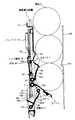
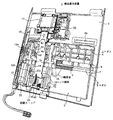
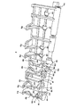
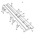
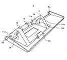
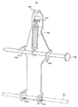
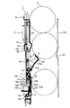
図1は、この発明の実施の形態にかかる商品搬出装置を示す要部断面図であり、ばねの付勢によって上ペダルが商品径に合わせて突出している様子を示している。また、図2は、商品搬出装置を示す正面斜視図、図3は、商品搬出装置を示す背面斜視図、図4は、上ペダルを示す正面斜視図、図5は、上ペダルを示す背面斜視図、図6は、下ペダルを示す正面斜視図、図7は、回動ストッパを示す正面斜視図、図8は、リンク部材を示す斜視図である。
【0013】
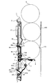
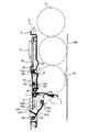
また、図9は、販売待機状態を示す要部断面図、図10は、下ペダルのロック状態が解除されるとともに、ソレノイドの引き始めにより上ペダルが商品に当接するまで突出する様子を示す要部断面図、図11は、ばねに引かれ商品径に追従して突出する上ペダルの様子を示す要部断面図、図12は、下から2番目の商品を上ペダルで保持した状態を示す要部断面図、図13は、下ペダルが復帰した状態を示す要部断面図である。
【0014】
商品搬出装置1の基板2には、開口部3が設けられており、この開口部3に商品搬出制御用の上ペダル4と下ペダル5とが、基板2および軸受部材12,13に軸支されたピン6,7によって回動自在に設けられている。基板2の開口部3の上縁部には、商品Gを後述する商品出口通路板100側に寄せて姿勢制御するためのガイド突部2aが設けられている。
【0015】
上ペダル4は、下ペダル5が閉状態になり、下から1番目の商品Gが落下搬出される際に、下から2番目の商品Gを支持するものであり、樹脂(たとえば、ポリアセタール)にて一体成形されている。この上ペダル4は、ピン6に装着されたねじりコイルばね8によって閉じる方向に付勢されている。
【0016】
また、上ペダル4のピン穴4aは、ピン6を挿通するためのものである。ストッパ片4bのストッパ面4eは、上ペダル4の最大開度時にピン22と当接して上ペダル4にかかる商品荷重を受け、当該上ペダル4の位置を最大開度でロックするものである。ガイド片4cは、ストッパ片4bから所定の間隔で立設され、リンク部材19が往復動する際に、ピン22が摺動する摺動溝4dをストッパ片4bとともに形成している。
【0017】
また、逃げ溝4fは、上ペダル4の閉状態時にピン22が上ペダル4に当たって閉動作を妨げないように形成したものである。爪部4gは、同一構成の商品搬出装置1を抱き合わせて設置したときに、対向する当該商品搬出装置1の上ペダル4が閉状態のときに互いに噛み合うように形成され、かつ、他方の上ペダル4の上縁部を乗り上げるように形成されている。
【0018】
逃げ穴4hは、同一構成の商品搬出装置1を抱き合わせて設置したときに、対向する当該商品搬出装置1の上ペダル4が閉状態のときに、ストッパ片4bの先端部を逃がし、設置時における装置全体の厚みが増加しないように形成したものである。また、突起部4kは、上ペダル4が最大開度の状態になるときに、軸受部材12,13の一部に当接して回動範囲を規制するためのものである。係止穴4mは、ねじりコイルばね8の一端を係止するためのものである。
【0019】
また、リンク部材19は、図8に示すように、ソレノイド17のプランジャ18に連結される係止部19bと、ピン22を係止する係止片19d、ピン22と自身を連結するばね64の一端を係止する係止部19cと、ピン24を挿通保持する係止穴19eを備えている。
【0020】
つぎに、下ペダル5について説明する。下ペダル5は、開状態において、商品通路10における下から1番目の商品Gを保持するものであり、図5に示すように、金属板の裏面に樹脂(たとえば、ポリアセタール)製の軸受台11を備えて構成されている。この下ペダル5は、ピン7に装着されたねじりコイルばね9によって、開く方向に付勢されている。
【0021】
下ペダル5のピン穴5a,11aは、ピン7を挿通するためのものである。係止爪5bは、軸受台11を係止するためのものである。軸受台11に設けた異形溝14は、後述する回動ストッパ20のピン25端部を摺動させ、このピン25を介して下ペダル5と回動ストッパ20とが連動するように、ピン25の動作範囲を規制するために形成したものである。すなわち、この異形溝14は、ピン25のロック位置を定める小径溝部14aと、ピン25のロック位置以外の動作範囲を定める大径溝部14bとから形成されている。
【0022】
軸受台11に設けた一対のガイド突起部15は、リンク部材19の両側を挟むように形成され、リンク部材19の上下方向の動作が左右方向にずれないように案内するためのものである。
【0023】
なお、図7において、商品出口通路板100は、大径の商品Gが収納できる通路幅となるように商品搬出装置1と対向配置されている。商品出口通路板100の突起部101は、いわゆるドリンク剤入りの瓶商品等の小径商品(図示せず)を、商品搬出装置1の上ペダル4側に寄せて当該商品を保持しやすい姿勢に制御するために設けたものである。
【0024】
つぎに回動ストッパ20について説明する。回動ストッパ20は、下ペダル5が商品荷重を受けられるように下ペダル5を最大開度でロックするとともに、商品販売時にそのロックが解除され、商品荷重によって下ペダル5が開口部3内に押し戻されるときの力を利用して、ピン24を介してリンク部材19を上方にスライドさせることにより、ソレノイド17がリンク部材19を引いて上ペダル4を開ける際にその駆動力を補助するためのものである。
【0025】
また、この回動ストッパ20は、軸受台11とともに、下ペダル5を最大開度でほぼ水平となるように支持できるように形成してある。これは、下から2番目の商品Gの高さ方向の位置は、積み上げられる商品Gの径によって差が生じるので、この差を、径の異なる商品Gを販売するときであっても、できるだけ小さくして、上ペダル4での保持を確実にするためである。
【0026】
この回動ストッパ20は、基板2および軸受部材12,13によって保持されたピン23によって下端部を回動自在に軸支され、このピン23に装着されたねじりコイルばね40によって開く方向に付勢されている。また、回動ストッパ20の上端部には、下ペダル5を最大開度でロックするためのピン25を備えている。
【0027】
このピン25の両端部は、下ペダル5の軸受台11の異形溝14内に配置され、下ペダル5が最大開度でロックされるときには、ピン25が異形溝14の小径溝部14aに位置し、それ以外のときには異形溝14の大径溝部14bに位置するようになっている。
【0028】
また、図6に示すように、回動ストッパ20のピン穴20a,20bは、ピン23,25を挿通するためのものである。ロック溝20cは、ピン24を係合させて回動ストッパ20の回動をロックするために設けたものである。下ペダル5のロック状態、すなわち、ピン24がロック溝20cに係合しているときには、ピン25は小径溝部14aに係合している。
【0029】
また、回動ストッパ20の傾斜摺動面20dは、回動ストッパ20の回動時にピン24が摺動するように形成したものである。すなわち、商品販売時にソレノイド17によりリンク部材19が引かれ、ピン24がロック溝20cから外されると、下ペダル5のロックが解除され、商品荷重によって下ペダル5が開口部3内に押し戻される。このとき、回動ストッパ20もピン23を回動中心にして開口部3内に押し戻されるので、ピン24が傾斜摺動面20dによって上方に摺動し、リンク部材19を上方に移動させるようになっている。
【0030】
なお、上述した各部材は、同一構成の商品搬出装置1を抱き合わせて設置する際に、相手方の部材と干渉しないように形成され、配設されている。
【0031】
つぎに動作について図1および図9〜図13に基づいて説明する。図9に示した販売待機状態において、ソレノイド17に通電すると、ソレノイド17がプランジャ18を介してリンク部材19を引く。このとき、ばね64は、初期の設定長さであり、張力は働いていない。
【0032】
続いて、図10に示すように、ソレノイド17が引き始めると、上ペダル4は、商品に当たるまで突出する。この突出量は、ばね64が伸びることによって調整され、大径商品の場合ほどばね64は伸びることとなる。
【0033】
また、リンク部材19先端のピン24が、回動ストッパ20のロック溝20cから外れる。このロックが外れると、回動ストッパ20上端部のピン25も異形溝14の小径溝部14aから外れて下ペダル5の開状態のロックが解除され、下ペダル5は所定の回動角度まで自由に回動できるようになる。
【0034】
また、図1および図11に示すように、上ペダル4は、ばね64に引っ張られている状態であるので、上ペダル4の前方の商品の落下動作に常に追従するように突出する。そして、商品Gの荷重によって下ペダル5が開口部3内に押し戻されると、回動ストッパ20もピン23を回動中心にして開口部3内に押し戻されるので、ピン24が傾斜摺動面20d上を上方に摺動してリンク部材19を上方に移動させるとともに、ピン25が大径溝部14bの内面に沿って移動する。
【0035】
このとき、上ペダル4の摺動溝4dと係合しているピン22も押し上げられ、上ペダル4を開かせるので、ソレノイド17がリンク部材19を引く力を補助することができる。これにより、上ペダル4に商品が当接して開きにくい場合であっても、上ペダル4が開く方向に回動力を付与できるから、上ペダル4が開きやすくなり、商品Gを確実に保持できる。
【0036】
そして、図12〜図13に示すように、商品Gが落下し、下ペダル5への商品荷重がかからなくなると、下ペダル5は、ねじりコイルばね9の付勢力によって開状態に復帰する。さらに、ソレノイド17の通電を切ると、リンク部材19がばね30の付勢力により引き下げられてピン22による上ペダル4のロックが解除され、上ペダル4は、ねじりコイルばね8の付勢力により閉じられて販売待機状態に戻る(図9参照)。
【0037】
以上のように、この実施の形態にかかる自動販売機の商品搬出装置によれば、ソレノイド17を大型化することなく上ペダル4の駆動力を十分に確保できるので、装置の薄型化を実現しつつ、種々の径の商品を販売できる。
【0038】
特に、リンク部材19は、上ペダル4の摺動溝4dを摺動することによって当該上ペダル4を開閉制御するピン22とばね64を介して連結されたものであるので、商品径に合わせて上ペダル4の突出タイミングをずらすことができ、大径商品から小径商品まで幅広く円滑に販売できる。
【0039】
【発明の効果】
以上説明したように、この発明にかかる自動販売機の商品搬出装置によれば、基板の開口部に回動自在に軸支され、当該開口部から商品通路側に突出することにより下から1番目の商品を保持する下ペダルと、前記基板の開口部に回動自在に軸支され、当該開口部から商品通路側に突出することにより下から2番目の商品を保持する上ペダルと、前記上ペダルおよび前記下ペダルを開閉制御するために駆動装置により往復動するリンク手段とを備え、径の異なる商品を前記商品通路幅を変更することなく搬出できるように形成され、前記各ペダルを当該商品通路側に交互に突出させて当該商品の搬出を制御するように形成した自動販売機の商品搬出装置において、前記リンク手段は、前記上ペダルの裏面に形成された摺動溝を摺動することによって当該上ペダルを開閉制御するピンと付勢手段を介して連結されたものであるので、下ペダルと上ペダルとのなす角が商品径に合わせて形成され、当該下ペダルと上ペダルとで商品を挟み込むようにして搬出することとなる。
【0040】
また、上ペダルは、下から1番目の商品が搬出される際に、当該商品と次販売商品との間に迅速に入り込むことができ、確実に次販売商品を保持することができる。したがって、商品径に合わせて上ペダルの突出タイミングをずらすことができ、大径商品から小径商品まで幅広く円滑に販売できる。
【図面の簡単な説明】
【図1】この発明の実施の形態にかかる商品搬出装置を示す要部断面図である。
【図2】商品搬出装置を示す正面斜視図である。
【図3】商品搬出装置を示す背面斜視図である。
【図4】上ペダルを示す正面斜視図である。
【図5】上ペダルを示す背面斜視図である。
【図6】下ペダルを示す正面斜視図である。
【図7】回動ストッパを示す正面斜視図である。
【図8】リンク部材を示す斜視図である。
【図9】販売待機状態を示す要部断面図である。
【図10】下ペダルのロック状態が解除されるとともに、ソレノイドの引き始めにより上ペダルが商品に当接するまで突出する様子を示す要部断面図である。
【図11】ばねに引かれ商品径に追従して突出する上ペダルの様子を示す要部断面図である。
【図12】下から2番目の商品を上ペダルで保持した状態を示す要部断面図である。
【図13】下ペダルが復帰した状態を示す要部断面図である。
【符号の説明】
1 商品搬出装置
2 基板
2a ガイド突部
3 開口部
4 上ペダル
4a ピン穴
4b ストッパ片
4c ガイド片
4d 摺動溝
4e ストッパ面
4f 逃げ溝
4g 爪部
4h 逃げ穴
4k 突起部
4m 係止穴
5 下ペダル
5a ピン穴
5b 係止爪
6、7 ピン
8、9 ねじりコイルばね
G 商品
10 商品通路
11 軸受台
11a ピン穴
12、13 軸受部材
12a、12b 長穴
14 異形溝
14a 小径溝部
14b 大径溝部
15 ガイド突起部
17 ソレノイド
18 プランジャ
19 リンク部材
19b、19c 係止部
19d 係止片
19e 係止穴
20 回動ストッパ
20a、20b ピン穴
20c ロック溝
20d 傾斜摺動面
22、23、24、25 ピン
30 ばね
40 ねじりコイルばね
50 売り切れスイッチ
64 ばね
100 商品出口通路板
101 突起部[0001]
BACKGROUND OF THE INVENTION
The present invention relates to a product unloading device for a vending machine, and more specifically, it is possible to sufficiently secure the driving force of the upper pedal without increasing the size of the driving device, and products having various diameters without adjusting the product passage width. In particular, the present invention relates to a product unloading device for a vending machine that can smoothly sell a wide range of products from large diameter products to small diameter products by shifting the protrusion timing of an upper pedal in accordance with the product diameter.
[0002]
[Prior art]
2. Description of the Related Art Conventionally, various vending machine merchandise unloading devices have been provided. These vending machine merchandise unloading devices are provided with a lower pedal for holding a lowermost product and an upper position of the lower pedal. An upper pedal for holding the second product is provided at the lower part of the product passage, and these pedals are alternately rotated and protruded toward the product passage to control the delivery of the product.
[0003]
In other words, since these merchandise carry-out devices regulate the merchandise passage dimensions based on the presence or absence of the pedal protrusion (the projection amount is always constant), when selling products with different shapes and outer diameter dimensions, In order to cope with this problem, a member that regulates the width of the passage is separately provided in the product passage, or a dedicated product carry-out device adapted to the product dimensions is provided.
[0004]
[Problems to be solved by the invention]
However, as is well known, containers for can drinks and plastic bottle drinks are distributed in various shapes and outer diameters, so if you try to sell products with different outer diameters at the same location in the product passage The product passage width has to be adjusted in accordance with the product diameter, which is troublesome, and depending on the shape of the container, there is a problem that it may not be suitable for the mechanism of the product carry-out device and may not be sold.
[0005]
On the other hand, in order to sell products with different shapes and outer diameters without adjusting the product passage width, it is necessary to set the product passage width according to the product with the maximum diameter in advance. In order to sell a small-diameter product in the combined product passage, it is necessary to increase the protruding amount of the above-mentioned product holding pedal.
[0006]
In order to drive the pedal against the product load applied to the pedal with the increased protrusion amount, a driving device such as a solenoid having a large driving force should be provided. Therefore, there is a problem that it cannot be provided and the driving force is insufficient.
[0007]
In addition, it has been desired to provide means capable of smoothly selling a wide range of products from large diameter products to small diameter products by shifting the protrusion timing of the upper pedal in accordance with the product diameter.
[0008]
The present invention has been made in view of the above, and can sufficiently secure the driving force of the upper pedal without increasing the size of the driving device, and can sell products of various diameters without adjusting the width of the product passage. The purpose is to provide a vending machine product unloading device, and in particular, the vending machine product unloading device which can smoothly sell a wide range of products from large diameter products to small diameter products by shifting the protrusion timing of the upper pedal according to the product diameter The purpose is to provide.
[0009]
[Means for Solving the Problems]
In order to achieve the above-mentioned object, a product carry-out device for a vending machine according to the present invention is pivotally supported by an opening of a substrate so as to be pivotable and protrudes from the opening toward the product passage 1 A lower pedal that holds the second product, an upper pedal that is pivotally supported by the opening of the substrate, and that holds the second product from the bottom by projecting to the product passage side from the opening, Link means that reciprocates by a driving device to control opening and closing of the upper pedal and the lower pedal, and formed so that products having different diameters can be carried out without changing the product passage width, In the merchandise carry-out device of the vending machine formed so as to alternately project the merchandise to the merchandise passage side, the link means slides in a slide groove formed on the back surface of the upper pedal. thing Therefore those linked via a pin and biasing means for opening and closing controls the on pedal.
[0010]
Since the upper pedal is rotated by a pin connected via the link means and the biasing means, the upper pedal is biased in the protruding direction. As a result, the angle formed by the lower pedal and the upper pedal is formed in accordance with the product diameter, and the product is carried out while sandwiching the product between the lower pedal and the upper pedal. Further, when the first product from the bottom is carried out, the upper pedal can quickly enter between the product and the next sale product, and can reliably hold the next sale product. Therefore, the protrusion timing of the upper pedal can be shifted in accordance with the product diameter, and a wide range of products from large diameter products to small diameter products can be sold smoothly.
[0011]
DETAILED DESCRIPTION OF THE INVENTION
DETAILED DESCRIPTION OF THE PREFERRED EMBODIMENTS Embodiments of a product carry-out device for a vending machine according to the present invention will be described below in detail with reference to the drawings. Note that the present invention is not limited to the embodiments.
[0012]
FIG. 1 is a cross-sectional view of a main part showing a product carry-out device according to an embodiment of the present invention, and shows a state in which an upper pedal protrudes in accordance with the product diameter by urging of a spring. 2 is a front perspective view showing the product carry-out device, FIG. 3 is a rear perspective view showing the product carry-out device, FIG. 4 is a front perspective view showing the upper pedal, and FIG. 5 is a rear perspective view showing the upper pedal. FIGS. 6 and 6 are front perspective views showing the lower pedal, FIG. 7 is a front perspective view showing the rotation stopper, and FIG. 8 is a perspective view showing the link member.
[0013]
FIG. 9 is a cross-sectional view of the main part showing the sales standby state, and FIG. 10 is a main part showing that the lower pedal is unlocked and the upper pedal protrudes until it comes into contact with the product when the solenoid starts to be pulled. FIG. 11 is a fragmentary sectional view, FIG. 11 is a fragmentary sectional view showing the state of the upper pedal that is pulled by a spring and protrudes following the product diameter, and FIG. 12 shows a state in which the second product from the bottom is held by the upper pedal. FIG. 13 is a fragmentary cross-sectional view showing a state where the lower pedal has returned.
[0014]
An
[0015]
The
[0016]
Further, the
[0017]
Further, the
[0018]
The
[0019]
As shown in FIG. 8, the
[0020]
Next, the
[0021]
The pin holes 5 a and 11 a of the
[0022]
The pair of
[0023]
In FIG. 7, the product
[0024]
Next, the
[0025]
The
[0026]
The
[0027]
Both ends of the
[0028]
Further, as shown in FIG. 6, the pin holes 20 a and 20 b of the
[0029]
The inclined sliding
[0030]
In addition, each member mentioned above is formed and arrange | positioned so that it may not interfere with the member of the other party, when tying and installing the goods carrying-out
[0031]
Next, the operation will be described with reference to FIG. 1 and FIGS. In the sales standby state shown in FIG. 9, when the
[0032]
Subsequently, as shown in FIG. 10, when the
[0033]
Further, the
[0034]
As shown in FIGS. 1 and 11, the
[0035]
At this time, the
[0036]
Then, as shown in FIGS. 12 to 13, when the product G falls and no product load is applied to the
[0037]
As described above, according to the commodity carry-out device of the vending machine according to this embodiment, the driving force of the
[0038]
In particular, the
[0039]
【The invention's effect】
As described above, according to the product carry-out device of the vending machine according to the present invention, it is pivotally supported by the opening portion of the substrate and protrudes from the opening portion to the product passage side so that it is first from the bottom. A lower pedal that holds the product, an upper pedal that is pivotally supported by the opening of the substrate, and that holds the second product from the bottom by protruding toward the product passage from the opening, and the upper Link means that reciprocates by a driving device to control opening and closing of the pedal and the lower pedal, and formed so that products having different diameters can be carried out without changing the width of the product passage. In the merchandise carry-out device of the vending machine formed so as to alternately project toward the passage side and control the carry-out of the merchandise, the link means slides in a slide groove formed on the back surface of the upper pedal. In Therefore, the angle between the lower pedal and the upper pedal is formed in accordance with the product diameter, and is connected to the pin for controlling the opening and closing of the upper pedal via the biasing means. The product will be carried out as if it were sandwiched.
[0040]
Further, when the first product from the bottom is carried out, the upper pedal can quickly enter between the product and the next sale product, and can reliably hold the next sale product. Therefore, the protrusion timing of the upper pedal can be shifted in accordance with the product diameter, and a wide range of products from large diameter products to small diameter products can be sold smoothly.
[Brief description of the drawings]
FIG. 1 is a cross-sectional view of an essential part showing a product carry-out apparatus according to an embodiment of the present invention.
FIG. 2 is a front perspective view showing a product carry-out device.
FIG. 3 is a rear perspective view showing the product carry-out device.
FIG. 4 is a front perspective view showing an upper pedal.
FIG. 5 is a rear perspective view showing an upper pedal.
FIG. 6 is a front perspective view showing a lower pedal.
FIG. 7 is a front perspective view showing a rotation stopper.
FIG. 8 is a perspective view showing a link member.
FIG. 9 is a cross-sectional view of a main part showing a sales standby state.
FIG. 10 is a cross-sectional view of a principal part showing a state in which the lower pedal is released and the upper pedal protrudes until it comes into contact with the product when the solenoid starts to be pulled.
FIG. 11 is a cross-sectional view of a principal part showing a state of an upper pedal which is pulled by a spring and protrudes following a product diameter.
FIG. 12 is a cross-sectional view of the main part showing a state in which the second product from the bottom is held by the upper pedal.
FIG. 13 is a cross-sectional view of a main part showing a state where the lower pedal is returned.
[Explanation of symbols]
DESCRIPTION OF
Claims (1)
前記基板の開口部に回動自在に軸支され、当該開口部から商品通路側に突出することにより下から2番目の商品を保持する上ペダルと、
前記上ペダルおよび前記下ペダルを開閉制御するために駆動装置により往復動するリンク手段と、
を備え、
径の異なる商品を前記商品通路幅を変更することなく搬出できるように形成され、前記各ペダルを当該商品通路側に交互に突出させて当該商品の搬出を制御するように形成した自動販売機の商品搬出装置において、
前記リンク手段は、前記上ペダルの裏面に形成された摺動溝を摺動することによって当該上ペダルを開閉制御するピンと付勢手段を介して連結されたことを特徴とする自動販売機の商品搬出装置。A lower pedal that is pivotally supported by the opening of the substrate and holds the first product from the bottom by projecting toward the product passage from the opening;
An upper pedal that is pivotally supported by the opening of the substrate and holds the second product from the bottom by protruding from the opening toward the product passage;
Link means that reciprocates by a driving device to control opening and closing of the upper pedal and the lower pedal;
With
A vending machine formed so that products having different diameters can be carried out without changing the width of the product passage, and the pedals are alternately protruded toward the product passage to control the delivery of the product. In the product unloading device,
A product of a vending machine characterized in that the link means is connected via a biasing means to a pin that controls opening and closing of the upper pedal by sliding in a sliding groove formed on the back surface of the upper pedal. Unloading device.
Priority Applications (1)
| Application Number | Priority Date | Filing Date | Title |
|---|---|---|---|
| JP2001304627A JP4457544B2 (en) | 2001-09-28 | 2001-09-28 | Vending machine product unloading device |
Applications Claiming Priority (1)
| Application Number | Priority Date | Filing Date | Title |
|---|---|---|---|
| JP2001304627A JP4457544B2 (en) | 2001-09-28 | 2001-09-28 | Vending machine product unloading device |
Publications (2)
| Publication Number | Publication Date |
|---|---|
| JP2003109098A JP2003109098A (en) | 2003-04-11 |
| JP4457544B2 true JP4457544B2 (en) | 2010-04-28 |
Family
ID=19124521
Family Applications (1)
| Application Number | Title | Priority Date | Filing Date |
|---|---|---|---|
| JP2001304627A Expired - Lifetime JP4457544B2 (en) | 2001-09-28 | 2001-09-28 | Vending machine product unloading device |
Country Status (1)
| Country | Link |
|---|---|
| JP (1) | JP4457544B2 (en) |
-
2001
- 2001-09-28 JP JP2001304627A patent/JP4457544B2/en not_active Expired - Lifetime
Also Published As
| Publication number | Publication date |
|---|---|
| JP2003109098A (en) | 2003-04-11 |
Similar Documents
| Publication | Publication Date | Title |
|---|---|---|
| JP2001188955A (en) | Vending machine product unloading device | |
| CN102568100A (en) | Automatic vendor | |
| JP4457544B2 (en) | Vending machine product unloading device | |
| JP4492020B2 (en) | Vending machine product unloading device | |
| JP4492010B2 (en) | Vending machine product unloading device | |
| JP4457543B2 (en) | Vending machine product unloading device | |
| JP4396073B2 (en) | Vending machine product unloading device | |
| JP4507478B2 (en) | Vending machine product unloading device | |
| JP4407086B2 (en) | Vending machine product unloading device | |
| JP4442073B2 (en) | Vending machine product unloading device | |
| JP4403680B2 (en) | Vending machine product unloading device | |
| JP3791413B2 (en) | Vending machine product unloading device | |
| JP5909640B2 (en) | Vending machine product unloading device | |
| JP4933010B2 (en) | Vending machine product unloading device | |
| JP2003077052A (en) | Vending machine product unloading device | |
| JP2003109095A (en) | Vending machine product unloading device | |
| JP4357210B2 (en) | Vending machine product dispensing device | |
| JP2003196727A (en) | Vending machine product unloading device | |
| JP2003077049A (en) | Vending machine product unloading device | |
| JP4186412B2 (en) | Vending machine product unloading device | |
| JP4288864B2 (en) | Vending machine product unloading device | |
| JP4010106B2 (en) | Vending machine product unloading device | |
| JP4360820B2 (en) | Vending machine product dispensing device | |
| JP3952653B2 (en) | Vending machine product unloading device | |
| JP2002049964A (en) | Vending machine product delivery device |
Legal Events
| Date | Code | Title | Description |
|---|---|---|---|
| A621 | Written request for application examination |
Free format text: JAPANESE INTERMEDIATE CODE: A621 Effective date: 20080812 |
|
| A977 | Report on retrieval |
Free format text: JAPANESE INTERMEDIATE CODE: A971007 Effective date: 20100108 |
|
| TRDD | Decision of grant or rejection written | ||
| A01 | Written decision to grant a patent or to grant a registration (utility model) |
Free format text: JAPANESE INTERMEDIATE CODE: A01 Effective date: 20100119 |
|
| A01 | Written decision to grant a patent or to grant a registration (utility model) |
Free format text: JAPANESE INTERMEDIATE CODE: A01 |
|
| A61 | First payment of annual fees (during grant procedure) |
Free format text: JAPANESE INTERMEDIATE CODE: A61 Effective date: 20100201 |
|
| R150 | Certificate of patent or registration of utility model |
Free format text: JAPANESE INTERMEDIATE CODE: R150 Ref document number: 4457544 Country of ref document: JP Free format text: JAPANESE INTERMEDIATE CODE: R150 |
|
| FPAY | Renewal fee payment (event date is renewal date of database) |
Free format text: PAYMENT UNTIL: 20130219 Year of fee payment: 3 |
|
| S531 | Written request for registration of change of domicile |
Free format text: JAPANESE INTERMEDIATE CODE: R313531 |
|
| FPAY | Renewal fee payment (event date is renewal date of database) |
Free format text: PAYMENT UNTIL: 20130219 Year of fee payment: 3 |
|
| R350 | Written notification of registration of transfer |
Free format text: JAPANESE INTERMEDIATE CODE: R350 |
|
| FPAY | Renewal fee payment (event date is renewal date of database) |
Free format text: PAYMENT UNTIL: 20130219 Year of fee payment: 3 |
|
| S111 | Request for change of ownership or part of ownership |
Free format text: JAPANESE INTERMEDIATE CODE: R313111 |
|
| FPAY | Renewal fee payment (event date is renewal date of database) |
Free format text: PAYMENT UNTIL: 20130219 Year of fee payment: 3 |
|
| R350 | Written notification of registration of transfer |
Free format text: JAPANESE INTERMEDIATE CODE: R350 |
|
| R250 | Receipt of annual fees |
Free format text: JAPANESE INTERMEDIATE CODE: R250 |
|
| R250 | Receipt of annual fees |
Free format text: JAPANESE INTERMEDIATE CODE: R250 |
|
| R250 | Receipt of annual fees |
Free format text: JAPANESE INTERMEDIATE CODE: R250 |
|
| R250 | Receipt of annual fees |
Free format text: JAPANESE INTERMEDIATE CODE: R250 |
|
| R250 | Receipt of annual fees |
Free format text: JAPANESE INTERMEDIATE CODE: R250 |
|
| R250 | Receipt of annual fees |
Free format text: JAPANESE INTERMEDIATE CODE: R250 |
|
| R250 | Receipt of annual fees |
Free format text: JAPANESE INTERMEDIATE CODE: R250 |
|
| R250 | Receipt of annual fees |
Free format text: JAPANESE INTERMEDIATE CODE: R250 |
|
| R250 | Receipt of annual fees |
Free format text: JAPANESE INTERMEDIATE CODE: R250 |