JP4455796B2 - Gear pump with drive mechanism and hydraulic tank - Google Patents
Gear pump with drive mechanism and hydraulic tank Download PDFInfo
- Publication number
- JP4455796B2 JP4455796B2 JP2001521902A JP2001521902A JP4455796B2 JP 4455796 B2 JP4455796 B2 JP 4455796B2 JP 2001521902 A JP2001521902 A JP 2001521902A JP 2001521902 A JP2001521902 A JP 2001521902A JP 4455796 B2 JP4455796 B2 JP 4455796B2
- Authority
- JP
- Japan
- Prior art keywords
- coupling piece
- hydraulic
- pump
- pumping device
- fluid
- Prior art date
- Legal status (The legal status is an assumption and is not a legal conclusion. Google has not performed a legal analysis and makes no representation as to the accuracy of the status listed.)
- Expired - Fee Related
Links
Images


Classifications
-
- F—MECHANICAL ENGINEERING; LIGHTING; HEATING; WEAPONS; BLASTING
- F04—POSITIVE - DISPLACEMENT MACHINES FOR LIQUIDS; PUMPS FOR LIQUIDS OR ELASTIC FLUIDS
- F04C—ROTARY-PISTON, OR OSCILLATING-PISTON, POSITIVE-DISPLACEMENT MACHINES FOR LIQUIDS; ROTARY-PISTON, OR OSCILLATING-PISTON, POSITIVE-DISPLACEMENT PUMPS
- F04C11/00—Combinations of two or more machines or pumps, each being of rotary-piston or oscillating-piston type; Pumping installations
-
- Y—GENERAL TAGGING OF NEW TECHNOLOGICAL DEVELOPMENTS; GENERAL TAGGING OF CROSS-SECTIONAL TECHNOLOGIES SPANNING OVER SEVERAL SECTIONS OF THE IPC; TECHNICAL SUBJECTS COVERED BY FORMER USPC CROSS-REFERENCE ART COLLECTIONS [XRACs] AND DIGESTS
- Y10—TECHNICAL SUBJECTS COVERED BY FORMER USPC
- Y10T—TECHNICAL SUBJECTS COVERED BY FORMER US CLASSIFICATION
- Y10T137/00—Fluid handling
- Y10T137/5109—Convertible
- Y10T137/5283—Units interchangeable between alternate locations
-
- Y—GENERAL TAGGING OF NEW TECHNOLOGICAL DEVELOPMENTS; GENERAL TAGGING OF CROSS-SECTIONAL TECHNOLOGIES SPANNING OVER SEVERAL SECTIONS OF THE IPC; TECHNICAL SUBJECTS COVERED BY FORMER USPC CROSS-REFERENCE ART COLLECTIONS [XRACs] AND DIGESTS
- Y10—TECHNICAL SUBJECTS COVERED BY FORMER USPC
- Y10T—TECHNICAL SUBJECTS COVERED BY FORMER US CLASSIFICATION
- Y10T137/00—Fluid handling
- Y10T137/8593—Systems
- Y10T137/85978—With pump
- Y10T137/86035—Combined with fluid receiver
- Y10T137/86059—Hydraulic power unit
Abstract
Description
【0001】
本発明は、油圧ポンプおよび駆動機構部により流体を圧送するデバイスであって、独立構成要素としての前記油圧ポンプは、付加的構成要素としての種々の形式の駆動機構部に対してユニット・システムの様式で連結され得ると共に、この目的のために結合片の形態であり、また、特に異なるタンク容量を有する種々の油圧タンクが第3の構成要素として配備され、且つ、前記油圧タンクは前記結合片の一側に対して接続可能であると共に該結合片の逆側または同一側にて該当駆動機構部に接続可能である流体圧送デバイスに関する。
【0002】
DE−A−1995 14 749は、油圧ポンプとしてのラジアル・ピストン・ポンプと、該ポンプを駆動する駆動機構部とにより流体を圧送する汎用デバイスを記述している。斯かる習用デバイスはまたユニット・システムにより構造がモジュール式であるが、独立構成要素はラジアル・ピストン・ポンプとともに基礎部材を形成しており、これに対応して該基礎部材は軸心方向に大寸に構築されることから、斯かる習用のポンプ・デバイスは全体が大寸となり、全ての設置条件で使用され得るもので無く、特に狭域的な設置条件下においては使用され得ない。しかも前記ラジアル・ピストン・ポンプに対しては個別の多数のピストン・ポンプ要素が必要であることから、動作時に故障する可能性もある。また非常に多種の部品に鑑みると、前記ラジアル・ピストン・ポンプを製造して油圧ポンプとして使用するのも不経済である。
【0003】
ポンプ・アセンブリとも称される斯かるポンプ・デバイスは、たとえばトラックの貨物昇降デッキ、自動車昇降ジャッキ、フォークリフトなどの分野において油圧機構により負荷を揚動かつ下降すべく使用される。また、多くの場合にはバッテリ電力のみが利用可能な自動車の分野おいては直流モータが駆動機構部として使用される一方、交流を利用し得る商用施設の分野においては交流モータを備えた適切なポンプ・デバイスが採用される。
【0004】
関連する従来の解決策(DE−U−296 01 201)においては、特殊な用途の各々に対して特殊な作動要件を満足する特殊なアセンブリ解決策が有効とされた。しかし、用途の各々に対して個別の技術概念が利用されることから、この公知の解決策を製造に適用するのは不経済であると共に、顧客の要件に関連して多数の異なる構造形状および構造要素が保存されねばならない。
【0005】
ポンプ・デバイス又はポンプ・アセンブリをモジュール式のユニット・システムで配置構成する概念を更に発展させたものとして、DE−A−32 27 926はフランジ状の台板を備えた油圧ユニットを配備することを提案しており、該台板の一方の側部表面上には、当該油圧ポンプを密閉収納するハウジングであって油圧媒体に対する容器の役割を果たすハウジングと共に油圧ポンプが着脱自在に締着され、且つ、他方の側部表面上には両方の側部表面に直交して延在する駆動シャフトを有する電気モータが前記ポンプの逆側となる様に着脱自在に取付けられる。斯かる従来の解決策の場合、前記油圧ポンプは油圧タンクの構成要素であることから、蓄積容量は減少する。一方、前記フランジ状の台板にはドリル孔、貫通孔などが配備されているが、これらの孔は全て、種々の油圧ポンプ、モータ、バルブ、制御要素などを取付けるための相互連結部を形成すると共に、これらの孔は前記フランジ状台板の一側もしくは周縁表面にて終端し、該表面には各構成要素およびそれらの接続部に対する締着手段が配備される。ポンプ・デバイスとしての前記習用の油圧ユニットはサイズが大きいことから、特に取付けに利用できるスペースが制限されたならば、全ての用途には採用され得ない。
【0006】
斯かる技術状況に基づくと本発明の目的は、製造コストが、故に全体的なコストが削減されると共に多数の顧客の要望を満足し得る様に習用の流体圧送デバイスを更に改良するに在る。本発明の目的はまた、タンク容器の容量を減少すること無く、非常に狭域的な設置条件で設置されてスペースを節約し乍らも現在の技術状況の対応製品と同様に効率的であるという、信頼性を以て作動するポンプ・ユニットを開発するに在る。斯かる目的は、請求項1において特定された特徴を有するデバイスにより達成される。
【0007】
請求項1の特徴部分にて特定された如く、結合片は一体片であると共に台板の形態であり、且つ、油圧ポンプは、各ギヤが完全に前記台板内に導入されて該台板に一体化された外接歯車ポンプであることから、可及的に最低個数の構成要素に依るコンパクトなユニットとしてのポンプ・デバイスを多数の用途に対し組み立て得る。その際には、顧客の指示により既に入手可能な構成要素を相互に組合せることで、販売可能なユニットを形成し得る。故に本発明に対して権利請求された前記デバイスはユニット・システムを提供することから、非常に多様な実施例を生成する上では低コストにて同一部品が使用される。
【0008】
外接歯車ポンプの形態の前記油圧ポンプが前記台板内に導入されて完全に一体化されることから、接続されるべきタンク・ユニットの容量全体が利用され得る。これに加え、前記外接歯車ポンプが一体化される結果として流体ラインおよび制御ラインの長さは減少されるが、斯かる減少は低圧損失を伴う動作において信頼性を保つものである。前記外接歯車ポンプが起動/駆動要素として2個のギヤのみを有するという事実により、スペースが節約されると共にコスト効率的となり、更には動作の信頼性が促進される。これに加え、前記外接歯車ポンプの設計計算は多様な用途に対するポンプの体積流量に基づいて容易に実施されると共に、ポンプの幾何的寸法は斯かる設計態様に対して更に容易に使用される。
【0009】
また故障の場合に、更には保守を目的として、前記油圧ポンプは前記結合片を置き換えることで容易に置き換えられ得るが、これは前記結合片がプレート形状であるが故に前記油圧ポンプ自体が修理および保守のために容易に接近可能だからである。
【0010】
本発明に対して権利請求されたデバイスの付加的実施例は、従属請求項において特定される。
以下においては、添付図面に示された実施例に基づき前記流体圧送デバイスを更に詳細に記述する。尚、各図は縮尺通りではない。
【0011】
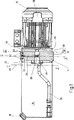
各図中に示されたデバイスは圧送のために使用されることから、駆動機構部12により駆動され得る油圧ポンプ10により流体を供給する。独立したモジュール式構成要素としての油圧ポンプ10はユニット・システムの様式で、付加的構成要素としての種々の形式の駆動機構部12と連結され得るが、この目的のために油圧ポンプ10はハウジング上の結合片要素14の形態である。第3の構成要素は特に種々のタンク容量を有する種々の油圧タンク16により表されているが、夫々の油圧タンク16は、結合片14の一側に対して接続可能であると共に、結合片14の逆側(図1および図3参照)または同一側(図2参照)にて夫々の駆動機構部12に接続可能である。図1乃至図3の図示内容においては本質的に唯一の形式の油圧タンク16であって、補充用連結管18により特に油圧流体などの流体が補充される油圧タンク16が示される。
【0012】
油圧ポンプ10として示された前記実施例に依れば、結合片14は送給手段としての2個の噛合ギヤ22を備えた外接歯車ポンプとしての歯車ポンプ20を有する。歯車ポンプ20の各ギヤ22は、結合片14のポンプ・チャンバ24内に取付けられると共に、結合片14の(不図示の)軸受ブッシュ内に回転可能に案内される。
【0013】
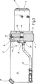
接続された所定の油圧タンク16の内部は吸引チャネル26により、特に吸引用フランジ28を介しての前記結合片への遷移部にてポンプ・チャンバ24の内部に接続される(図1乃至図3参照)。駆動機構部12が油圧タンク16の内側に一体化されるという図2に示された代替的ユニットの場合、吸引チャネル26は省略され得ると共に、この場合には駆動機構部12上に取付けられた吸引用フランジ28を介して流体は直接的に送給される。
【0014】
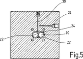
各図に示された視認方向において結合片14の内部には、ポンプ・チャンバ24を外部に接続して流体を導く送給ライン30が在る。外部へと延在する送給ライン30の自由端上にて該送給ライン30はスプリング負荷式戻り弁32により閉成されるが、該戻り弁32は、昇降デッキ、自動車昇降ジャッキなどに対する揚動デバイスの形態の使用デバイスに対して加圧液体を供給すべく油圧ポンプ10が作動を開始するや否や、前記スプリングの力を克服して開成する。特に図4乃至図6に示された如く、過負荷保護として圧力ピークから前記油圧システムを保護すべく(不図示の)圧力保護機構に接続された分岐ライン34は、送給ライン30内に直交して開口される。図4および図6に示された如く吸引用フランジ28の供給用開口は歯車ポンプ20を備えたポンプ・チャンバ24内に部分的にのみ開口する。
【0015】
使用された駆動機構部12は、特に図1および図2に示された如き交流モータ36、または、図3に示された如き直流モータ38などの電気モータである。図2に示された交流モータ36は、油圧タンク16の内側に取付けられることから、該タンクの一体的部分である。この場合には所謂るオイル内モータを備えた関連ポンプ・アセンブリが僅かなスペースを占有することから、油圧タンク16内で利用可能な流体の量も減少する。尚、不図示の実施例においては駆動機構部12として油圧駆動機構部も想起され得る。図1乃至図3に見られる如く結合片14はその一方の自由端上にて、夫々の油圧タンク16の自由端が重なり得るフランジ要素40を有し、適切な重なり箇所にはシール・リング形態のシール手段42が取付けられる。逆側において結合片14は、前記油圧ポンプおよび/または駆動機構部12に対して蓋体の様に接続され得る別のフランジ要素44を有する。
【0016】
付加的なフランジ要素44はその外側寸法がフランジ要素40に合致すると共に、フランジ要素40と同様に、図2に示された如くタンク16が該他方のフランジ要素44上に取付けられたときにシール手段42と接触する径方向凹所46を外周縁に備えている。前記2個のフランジ要素40、44は中央にて、吸引用フランジ28を挿入するための、または、駆動機構部12の適切な駆動ライン48を導入する環状凹所を有する。故に駆動機構部12はその駆動ライン48により油圧ポンプ10に連結され得るが、少なくとも他方のフランジ要素44の内側にて駆動ライン48の部位にはリング・シール形態の流体シール50が存在する。この様にして、示されたシール手段を用いることで、前記ポンプ・デバイスの内部は信頼性を以て外部から流体シールされる。
【0017】
各図の視認方向において種々の駆動機構部12を備えたモジュール式のユニット・システムを更に説明すると、結合片14の頂部には、ボア52により結合片14に接続され得る(不図示の)制御機構が存在し得る。適切な制御機構は、使用デバイスに対して流体を送給する油圧制御要素、並びに、油圧制御ユニット全体を含み得る。前記モジュール式ポンプ・アセンブリの個々の構成要素は、習用のネジ結合により相互に接続され得る。油圧要素16は密閉構造ユニットとして機能することから、前記ポンプ・アセンブリは密閉システムとして作動し、すなわち油圧タンク16の流体容積は、起動されるべき使用デバイスに対して供給を行うためにのみ使用される。また、従来の解決策と対照的に流体導通ラインは結合片14内に一体化されることから、別体的なシールまたは配管は不要である。特に前記各フランジ要素は鋳造要素からコスト効率的に理想的に製造され得る。問題となる駆動機構部12は外部要素により表されると共に、タンク16の材料実施例はプラスチックまたは薄寸鋼鉄とされ得る。歯車ポンプ20の実施例自体は、圧力補償されまたは圧力補償されない。
【0018】
各図の視認方向において外接ギヤ22を備えた歯車ポンプ20は本来的に送給ライン30と共に、フランジ状の結合片14の垂直延在中央平面内に存在し、且つ、各ギヤ22に対する駆動シャフトは駆動ライン48の長手軸心と共に、問題となる長手方向中央平面であって図1におけるII−II線により表された長手方向中央平面(図5参照)に直交する平面内に存在する。駆動ライン48の自由端は2個のギヤ22の一方に対する円筒状駆動要素56内の凹所54に係合される接続ピンの如き形態とされ得るものであって、この様にして駆動ライン48により一方のギヤ22のみが駆動され得ると共に、この様に駆動されるギヤ22は2群のギヤ歯の対応噛合により圧送プロセスに対して他方のギヤ22を同調させる。
【0019】
発明に対して権利請求された前記デバイスに依れば油圧ポンプ10としての結合片14は、任意に油圧タンク16、駆動機構部12、不図示の制御機構ならびに使用デバイスに連結されてシステム解決策を形成し得る中央構造ユニットである。結合片14は、言及された送給ラインおよび制御ラインと歯車ポンプ20のギヤ要素のみにより貫通される取付プレートの如き一体的で中実な台板要素の形態である。外接歯車ポンプ20の各ギヤ22は結合片14の中実台板の略々中央に取付けられることから、作動の間においては振動の少ない駆動が行われると共に、この状態により連続的な流体流の送給が促進される。
【図面の簡単な説明】
【図1】 種々の駆動ユニットを備えると共に部分的に断面とされ且つ部分的に側面視とされたポンプ・デバイスを示す図である。
【図2】 種々の駆動ユニットを備えると共に部分的に断面とされ且つ部分的に側面視とされたポンプ・デバイスを示す図である。
【図3】 種々の駆動ユニットを備えると共に部分的に断面とされ且つ部分的に側面視とされたポンプ・デバイスを示す図である。
【図4】 図1のI−I線に沿った断面図である。
【図5】 図1のII−II線に沿った断面図である。
【図6】 図1のIII−III線に沿った断面図である。[0001]
The present invention is a device for pumping fluid by means of a hydraulic pump and a drive mechanism, wherein the hydraulic pump as an independent component is a unit system with respect to various types of drive mechanisms as additional components. Various hydraulic tanks, which can be connected in a manner and are in the form of coupling pieces for this purpose, and in particular with different tank capacities, are provided as a third component, and the hydraulic tanks are connected to the coupling pieces It is related with the fluid pressure feeding device which can be connected with respect to one side and can be connected to a corresponding drive mechanism part on the opposite side or the same side of this coupling piece.
[0002]
DE-A-1995 14 749 describes a general-purpose device that pumps fluid by means of a radial piston pump as a hydraulic pump and a drive mechanism that drives the pump. Such customary devices are also modular in structure by the unit system, but the independent components together with the radial piston pump form a base member, correspondingly the base member is large in the axial direction. As such, the conventional pump device is large in size and cannot be used in all installation conditions, especially under narrow installation conditions. Moreover, since the radial piston pump requires a large number of individual piston pump elements, there is a possibility of failure during operation. In view of the very wide variety of parts, it is also uneconomical to manufacture the radial piston pump and use it as a hydraulic pump.
[0003]
Such pump devices, also referred to as pump assemblies, are used, for example, in the fields of truck cargo lift decks, automobile lift jacks, forklifts and the like to lift and lower loads by hydraulic mechanisms. In many cases, a DC motor is used as a drive mechanism in the field of automobiles where only battery power can be used, while in a commercial facility where AC can be used, an appropriate motor equipped with an AC motor is used. A pump device is adopted.
[0004]
In a related conventional solution (DE-U-296 01 201), a special assembly solution that fulfills special operating requirements for each special application has been validated. However, because separate technical concepts are utilized for each of the applications, it is uneconomical to apply this known solution to manufacturing and a number of different structural shapes and Structural elements must be preserved.
[0005]
As a further development of the concept of arranging the pump device or pump assembly in a modular unit system, DE-A-32 27 926 deploys a hydraulic unit with a flanged base plate. A hydraulic pump is detachably fastened together with a housing that hermetically accommodates the hydraulic pump and serves as a container for the hydraulic medium on one side surface of the base plate; and On the other side surface, an electric motor having a drive shaft extending perpendicular to both side surfaces is detachably attached so as to be on the opposite side of the pump. In the case of such a conventional solution, since the hydraulic pump is a component of the hydraulic tank, the storage capacity is reduced. On the other hand, the flange-shaped base plate is provided with drill holes, through holes, etc., all of which form interconnections for mounting various hydraulic pumps, motors, valves, control elements, etc. In addition, these holes terminate at one side or peripheral surface of the flange-shaped base plate, and fastening means for the respective components and their connecting portions is provided on the surface. The customary hydraulic unit as a pump device is large in size and cannot be employed in all applications, especially if the space available for installation is limited.
[0006]
Based on such a technical situation, the object of the present invention is to further improve the custom fluid pumping device so that the manufacturing cost can be reduced and therefore the overall cost can be reduced and the requirements of many customers can be satisfied. . The object of the present invention is also to be installed in very narrow installation conditions without reducing the capacity of the tank container, saving space and being as efficient as the corresponding products in the current state of the art. The development of a pump unit that operates with reliability. Such an object is achieved by a device having the features specified in claim 1.
[0007]
As specified in the characterizing portion of claim 1, the coupling piece is an integral piece and is in the form of a base plate, and the hydraulic pump is configured such that each gear is completely introduced into the base plate. Therefore, the pump device as a compact unit with as few components as possible can be assembled for multiple applications. In that case, the unit which can be sold can be formed by mutually combining components already available in accordance with customer instructions. Thus, since the device claimed for the present invention provides a unit system, the same components are used at a low cost to produce a very diverse embodiment.
[0008]
Since the hydraulic pump in the form of an external gear pump is introduced into the base plate and fully integrated, the entire capacity of the tank units to be connected can be utilized. In addition, the length of the fluid and control lines is reduced as a result of the integration of the external gear pump, but such a reduction is reliable in operation with low pressure losses. The fact that the external gear pump has only two gears as actuating / driving elements saves space and is cost effective, and further promotes operational reliability. In addition, the design calculation of the external gear pump is easily performed based on the pump volume flow for various applications, and the pump geometry is more easily used for such design.
[0009]
In the case of a failure, the hydraulic pump can be easily replaced by replacing the coupling piece for the purpose of maintenance, but the hydraulic pump itself is repaired and repaired because the coupling piece is plate-shaped. This is because it is easily accessible for maintenance.
[0010]
Additional embodiments of the device claimed for the invention are specified in the dependent claims.
In the following, the fluid pumping device will be described in more detail based on the embodiments shown in the accompanying drawings. Each figure is not to scale.
[0011]
Since the device shown in each figure is used for pumping, fluid is supplied by a
[0012]
According to the embodiment shown as a
[0013]
The interior of the connected predetermined
[0014]
Inside the
[0015]
The
[0016]
The
[0017]
The modular unit system with
[0018]
The
[0019]
According to the device claimed for the invention, the
[Brief description of the drawings]
FIG. 1 shows a pump device with various drive units and partly in section and partly in side view.
FIG. 2 shows a pump device with various drive units and partly in section and partly in side view.
FIG. 3 shows a pump device with various drive units and partly in section and partly in side view.
4 is a cross-sectional view taken along the line II of FIG.
FIG. 5 is a cross-sectional view taken along the line II-II in FIG.
6 is a cross-sectional view taken along line III-III in FIG.
Claims (10)
前記結合片(14)はベースプレートの形態をなしており、
前記結合片(14)は、前記フランジ要素(40)とは反対側に他のフランジ要素(44)を有しており、該他のフランジ要素(44)の外部寸法は前記フランジ要素(40)の外部寸法に適合するようになっており、
前記両方のフランジ要素(40、44)はシール手段(42)に係合する径方向凹所(46)をそれらの外周縁に備えており、前記シール手段(42)は前記油圧タンク(16)および前記駆動機構部(12)の自由端により重なり得るようになっており、前記油圧タンク(16)および前記駆動機構部(12)は前記駆動機構部の一側に一緒に連結されている、流体圧送デバイス。A fluid pumping device that pumps fluid by a hydraulic pump (10) and a drive mechanism (12), wherein the hydraulic pump (10) as an independent component is an external gear pump (20), and the hydraulic pump (10 ) Can be connected in the form of a unit system to various types of drive mechanisms (12) as additional components and for this purpose is in the form of a coupling piece (14) and in particular a different tank Various hydraulic tanks (16) having a capacity are arranged as a third component, and the hydraulic tank (16) can be connected to the coupling piece (14) on one side of the coupling piece (14). The drive mechanism (12) is connectable to the coupling piece (14) on the other side of the coupling piece (14), and for this purpose the coupling piece (14) is at least on one side thereof. In a fluid pressure feeding device having a flange element (40), and sealing means (42) provided between the coupling piece (14), the drive mechanism (12) and the hydraulic tank (16). ,
The coupling piece (14) is in the form of a base plate;
The coupling piece (14) has another flange element (44) on the opposite side of the flange element (40), and the external dimension of the other flange element (44) is the flange element (40). To fit the external dimensions of
Both flange elements (40, 44) are provided with a radial recess (46) at their outer periphery that engages the sealing means (42), the sealing means (42) being connected to the hydraulic tank (16). The hydraulic tank (16) and the drive mechanism (12) are connected together on one side of the drive mechanism, Fluid pumping device.
Applications Claiming Priority (3)
| Application Number | Priority Date | Filing Date | Title |
|---|---|---|---|
| DE19942567.1 | 1999-09-07 | ||
| DE19942567A DE19942567A1 (en) | 1999-09-07 | 1999-09-07 | Fluid pumping device |
| PCT/EP2000/008643 WO2001018397A1 (en) | 1999-09-07 | 2000-09-05 | Gear pump with a drive and a hydraulic tank |
Publications (3)
| Publication Number | Publication Date |
|---|---|
| JP2003508688A JP2003508688A (en) | 2003-03-04 |
| JP2003508688A5 JP2003508688A5 (en) | 2007-02-08 |
| JP4455796B2 true JP4455796B2 (en) | 2010-04-21 |
Family
ID=7921032
Family Applications (1)
| Application Number | Title | Priority Date | Filing Date |
|---|---|---|---|
| JP2001521902A Expired - Fee Related JP4455796B2 (en) | 1999-09-07 | 2000-09-05 | Gear pump with drive mechanism and hydraulic tank |
Country Status (6)
| Country | Link |
|---|---|
| US (1) | US6786709B1 (en) |
| EP (1) | EP1210519B1 (en) |
| JP (1) | JP4455796B2 (en) |
| AT (1) | ATE253175T1 (en) |
| DE (2) | DE19942567A1 (en) |
| WO (1) | WO2001018397A1 (en) |
Families Citing this family (17)
| Publication number | Priority date | Publication date | Assignee | Title |
|---|---|---|---|---|
| US6572339B2 (en) | 2001-03-30 | 2003-06-03 | Eaton Corporation | Positive displacement fluid pump having improved fill characteristics |
| DE10131750A1 (en) * | 2001-07-03 | 2003-01-16 | Bosch Rexroth Ag | hydraulic power unit |
| ATE343063T1 (en) * | 2002-09-17 | 2006-11-15 | Maag Pump Systems Ag | DEVICE WITH A GEAR PUMP AND A DIRECT DRIVE AND AN EXTRUSION SYSTEM |
| US20040146408A1 (en) * | 2002-11-14 | 2004-07-29 | Anderson Robert W. | Portable air compressor/tank device |
| DE10306006B4 (en) * | 2003-02-12 | 2005-02-24 | Knapp, Jürgen Michael | hydraulic module |
| DE102004018909B4 (en) * | 2004-04-15 | 2007-08-09 | Jung Hebe- Und Transporttechnik Gmbh | hydraulic device |
| DE102004054831A1 (en) * | 2004-11-12 | 2006-05-24 | Gisela Weber | Gear pump unit has motor shaft mounted in rear motor cover and pump head housing, and coupling is fitted on forward end of motor shaft, whereby motor shaft with coupling extends through pump head housing |
| JP4820552B2 (en) * | 2005-01-19 | 2011-11-24 | カヤバ工業株式会社 | Hydraulic control device and hydraulic drive unit including the hydraulic control device |
| EP2025934B1 (en) * | 2007-08-07 | 2009-08-05 | HAWE Hydraulik SE | Motor pump unit |
| DE102008058283A1 (en) * | 2008-11-20 | 2010-05-27 | Wilhelm Karmann Gmbh | Hydraulic unit with a tank |
| CA2770867C (en) * | 2011-03-08 | 2018-11-06 | Synerject Llc | In-tank fluid transfer assembly |
| EP2746590B1 (en) * | 2012-12-19 | 2016-03-09 | Bucher Hydraulics S.p.A. | Power unit to move at least a hydraulic actuator |
| DE102013105445B4 (en) * | 2013-05-28 | 2015-08-20 | Pintsch Bubenzer Gmbh | Function unit and electro-hydraulic brake release device with such a |
| US9753443B2 (en) | 2014-04-21 | 2017-09-05 | Synerject Llc | Solenoid systems and methods for detecting length of travel |
| US9997287B2 (en) | 2014-06-06 | 2018-06-12 | Synerject Llc | Electromagnetic solenoids having controlled reluctance |
| WO2015191348A1 (en) | 2014-06-09 | 2015-12-17 | Synerject Llc | Methods and apparatus for cooling a solenoid coil of a solenoid pump |
| DE102016010669A1 (en) | 2016-08-29 | 2018-03-01 | Hydac Fluidtechnik Gmbh | Motor-pump device |
Family Cites Families (12)
| Publication number | Priority date | Publication date | Assignee | Title |
|---|---|---|---|---|
| US1218300A (en) * | 1915-11-20 | 1917-03-06 | George F Nelson | Vacuum-pump. |
| US2984187A (en) * | 1956-02-20 | 1961-05-16 | Thompson Ramo Wooldridge Inc | Power steering pump |
| US3515167A (en) | 1968-08-22 | 1970-06-02 | Ernest J Svenson | Hydraulic and electrical power unit |
| DE3227926C4 (en) * | 1982-07-27 | 1995-07-13 | Knapp Mikrohydraulik Gmbh | Hydraulic unit |
| NL9500190A (en) * | 1995-02-02 | 1995-06-01 | Applied Power Inc | Hydraulic power unit for a hydraulic system. |
| DE19514749A1 (en) * | 1995-04-21 | 1996-10-24 | Bosch Gmbh Robert | Hydrostatic radial piston pump |
| DE19627405B4 (en) * | 1996-07-06 | 2004-10-21 | Zf Friedrichshafen Ag | pump assembly |
| JP3667034B2 (en) * | 1996-07-17 | 2005-07-06 | 光洋精工株式会社 | Electric pump |
| US6158983A (en) * | 1997-04-24 | 2000-12-12 | Trw Inc. | Pump having muffler for attenuating noise |
| DE19726134A1 (en) * | 1997-06-20 | 1998-12-24 | Bosch Gmbh Robert | Hydraulic power pack |
| DE19833372A1 (en) * | 1998-07-24 | 2000-01-27 | Zahnradfabrik Friedrichshafen | Gear pump for vehicle power steering, integrated in casing and surrounded by absorber cavity and induction cavity |
| FR2789446B1 (en) * | 1999-02-04 | 2002-03-08 | Hydroperfect Internat Hpi | HYDRAULIC PUMP OF THE GEAR TYPE AND ELECTRIC PUMP GROUP EQUIPPED WITH SUCH A PUMP |
-
1999
- 1999-09-07 DE DE19942567A patent/DE19942567A1/en not_active Withdrawn
-
2000
- 2000-09-05 DE DE50004267T patent/DE50004267D1/en not_active Expired - Lifetime
- 2000-09-05 WO PCT/EP2000/008643 patent/WO2001018397A1/en active IP Right Grant
- 2000-09-05 US US10/069,392 patent/US6786709B1/en not_active Expired - Fee Related
- 2000-09-05 EP EP00962440A patent/EP1210519B1/en not_active Expired - Lifetime
- 2000-09-05 AT AT00962440T patent/ATE253175T1/en not_active IP Right Cessation
- 2000-09-05 JP JP2001521902A patent/JP4455796B2/en not_active Expired - Fee Related
Also Published As
| Publication number | Publication date |
|---|---|
| DE50004267D1 (en) | 2003-12-04 |
| ATE253175T1 (en) | 2003-11-15 |
| US6786709B1 (en) | 2004-09-07 |
| WO2001018397A1 (en) | 2001-03-15 |
| DE19942567A1 (en) | 2001-03-22 |
| EP1210519B1 (en) | 2003-10-29 |
| EP1210519A1 (en) | 2002-06-05 |
| JP2003508688A (en) | 2003-03-04 |
Similar Documents
| Publication | Publication Date | Title |
|---|---|---|
| JP4455796B2 (en) | Gear pump with drive mechanism and hydraulic tank | |
| EP2463556B1 (en) | Electric pump unit | |
| CA2529702C (en) | Hydraulic controller and hydraulic drive unit provided with said hydraulic controller | |
| US7179070B2 (en) | Variable capacity pump/motor | |
| US20080031763A1 (en) | Variable capacity pump/motor | |
| KR101430848B1 (en) | Pump | |
| EP2673510B1 (en) | Combined power take-off and hydraulic pump assembly | |
| US20090041594A1 (en) | Variable displacement type gear pump | |
| CA2063625C (en) | Improved transfer pump | |
| US4799865A (en) | Intermittent service screw compressor | |
| US3738784A (en) | Pump housing for use with top mounted or remote mounted reservoirs | |
| US6578357B1 (en) | Regulating device for hydraulic working tools | |
| US5662462A (en) | Sealing arrangement for a hydraulic motor and pump | |
| KR20190104544A (en) | Especially for vehicle hydraulic pumps | |
| US20070243081A1 (en) | Hydraulic pump, hydraulic pump unit, and hydraulic driving unit | |
| US8636487B2 (en) | Dual stage pump having intermittent mid-shift load supports | |
| CN101435444B (en) | Hydraulic device | |
| US6840042B1 (en) | Internal filter | |
| JP2004239269A (en) | Two-throw gear pump or motor | |
| US20150132170A1 (en) | Pump unit | |
| JPH07332254A (en) | Two-throw gear pump or motor | |
| JPH11166483A (en) | Motor-driven pump device | |
| JPS6227282B2 (en) | ||
| JPS58167891A (en) | Rotary vane pump | |
| CN201155458Y (en) | Compact type immersed three screw-rod pump for lubrication |
Legal Events
| Date | Code | Title | Description |
|---|---|---|---|
| A521 | Request for written amendment filed |
Free format text: JAPANESE INTERMEDIATE CODE: A523 Effective date: 20061212 |
|
| A621 | Written request for application examination |
Free format text: JAPANESE INTERMEDIATE CODE: A621 Effective date: 20061212 |
|
| A131 | Notification of reasons for refusal |
Free format text: JAPANESE INTERMEDIATE CODE: A131 Effective date: 20090818 |
|
| A521 | Request for written amendment filed |
Free format text: JAPANESE INTERMEDIATE CODE: A523 Effective date: 20091026 |
|
| TRDD | Decision of grant or rejection written | ||
| A01 | Written decision to grant a patent or to grant a registration (utility model) |
Free format text: JAPANESE INTERMEDIATE CODE: A01 Effective date: 20100105 |
|
| A01 | Written decision to grant a patent or to grant a registration (utility model) |
Free format text: JAPANESE INTERMEDIATE CODE: A01 |
|
| A61 | First payment of annual fees (during grant procedure) |
Free format text: JAPANESE INTERMEDIATE CODE: A61 Effective date: 20100204 |
|
| FPAY | Renewal fee payment (event date is renewal date of database) |
Free format text: PAYMENT UNTIL: 20130212 Year of fee payment: 3 |
|
| R150 | Certificate of patent or registration of utility model |
Free format text: JAPANESE INTERMEDIATE CODE: R150 |
|
| LAPS | Cancellation because of no payment of annual fees |