JP4455295B2 - Recording apparatus and data processing method of recording apparatus - Google Patents
Recording apparatus and data processing method of recording apparatus Download PDFInfo
- Publication number
- JP4455295B2 JP4455295B2 JP2004341685A JP2004341685A JP4455295B2 JP 4455295 B2 JP4455295 B2 JP 4455295B2 JP 2004341685 A JP2004341685 A JP 2004341685A JP 2004341685 A JP2004341685 A JP 2004341685A JP 4455295 B2 JP4455295 B2 JP 4455295B2
- Authority
- JP
- Japan
- Prior art keywords
- data
- recording
- block
- stored
- address
- Prior art date
- Legal status (The legal status is an assumption and is not a legal conclusion. Google has not performed a legal analysis and makes no representation as to the accuracy of the status listed.)
- Expired - Fee Related
Links
Images


Classifications
-
- G—PHYSICS
- G06—COMPUTING; CALCULATING OR COUNTING
- G06K—GRAPHICAL DATA READING; PRESENTATION OF DATA; RECORD CARRIERS; HANDLING RECORD CARRIERS
- G06K15/00—Arrangements for producing a permanent visual presentation of the output data, e.g. computer output printers
- G06K15/02—Arrangements for producing a permanent visual presentation of the output data, e.g. computer output printers using printers
- G06K15/10—Arrangements for producing a permanent visual presentation of the output data, e.g. computer output printers using printers by matrix printers
- G06K15/102—Arrangements for producing a permanent visual presentation of the output data, e.g. computer output printers using printers by matrix printers using ink jet print heads
-
- H—ELECTRICITY
- H04—ELECTRIC COMMUNICATION TECHNIQUE
- H04N—PICTORIAL COMMUNICATION, e.g. TELEVISION
- H04N1/00—Scanning, transmission or reproduction of documents or the like, e.g. facsimile transmission; Details thereof
- H04N1/46—Colour picture communication systems
- H04N1/50—Picture reproducers
- H04N1/504—Reproducing the colour component signals line-sequentially
Description
本発明は記録装置、及び、記録装置のデータ処理方法に関し、より詳細には、複数の記録素子が所定方向に配列された記録素子列を複数有する記録ヘッドを、記録素子の配列方向と交差する方向に走査させて記録を行う記録装置における、記録データの処理に関するものである。
The present invention is a recording apparatus, and relates to a data processing how the recording apparatus, and more particularly, a recording head in which a plurality of recording elements having a plurality of recording element arrays are arranged in a predetermined direction, the arrangement direction of the recording element The present invention relates to processing of recording data in a recording apparatus that performs recording by scanning in intersecting directions.
例えばワードプロセッサ、パーソナルコンピュータ、ファクシミリ等に於ける情報出力装置として、所望される文字や画像等の情報を用紙やフィルム等シート状の記録媒体に記録を行うプリンタが広く使用されている。 For example, as information output devices in word processors, personal computers, facsimiles, and the like, printers that record desired information such as characters and images on a sheet-like recording medium such as paper or film are widely used.
プリンタの記録方式としては様々な方式が知られているが、用紙等の記録媒体に非接触記録が可能である、カラー化が容易である、静粛性に富む、等の理由でインクジェット方式が近年特に注目されており、又その構成としては、所望される記録情報に応じてインクを吐出する記録ヘッドを搭載したキャリッジを用紙等の記録媒体の搬送方向と交差する方向に往復走査させながら記録を行なう、シリアル記録方式が安価で小型化が容易などの点から一般的に広く用いられている。 Various types of recording methods are known for printers, but inkjet methods have recently been used for reasons such as non-contact recording on recording media such as paper, easy colorization, and high quietness. In particular, as a configuration, recording is performed while reciprocally scanning a carriage equipped with a recording head for ejecting ink according to desired recording information in a direction crossing the conveyance direction of a recording medium such as paper. In general, the serial recording method is widely used because it is inexpensive and easy to downsize.
従来、記録ヘッドを搭載したキャリッジを記録媒体上で走査させて記録を行うために、記録ヘッドの走査方向の記録領域を複数の領域に分割し、分割された領域単位の記録データを格納するバッファを有する記録装置(印刷装置)が知られている。 2. Description of the Related Art Conventionally, in order to perform recording by scanning a carriage mounted with a recording head on a recording medium, a recording area in the scanning direction of the recording head is divided into a plurality of areas, and recording data for each divided area is stored. There is known a recording apparatus (printing apparatus) having
このような記録装置では、分割された領域単位の記録データをバッファに格納する際に、色毎にデータの格納領域を切替える情報と格納可能なバッファ残量及び書き込みアドレス更新量の比較の結果とに基づき、領域単位の記録データの書き込みアドレス情報を、色毎に制御する書き込み制御部を備えている(特許文献1)。 In such a recording apparatus, when recording data of divided area units is stored in the buffer, information for switching the storage area of the data for each color and the result of comparison between the remaining buffer capacity and the write address update amount Is provided with a write control unit for controlling the write address information of the recording data for each area for each color (Patent Document 1).
また、バッファに格納された記録データを読み出すための読み出しアドレス情報を色毎に制御する読み出し制御部と、読み出しアドレス情報に基づいて読み出された記録データに従い、分割された領域単位の記録データを生成する記録データ生成手段とを備えている。 In addition, a read control unit that controls the read address information for reading the record data stored in the buffer for each color, and the record data in units of areas divided according to the record data read based on the read address information Recording data generating means for generating.
このように構成された従来の記録装置にホストコンピュータから転送される記録データに対しては、ホストコンピュータ(プリンタドライバ)によって、走査方向(ラスタ方向)における位置の調整(レジスト調整)を施されている(特許文献2)。
しかしながら、記録装置に転送する記録データは記録・非記録を表す1ビット(2値)で表現されるのが一般的であるが、通常ホストコンピュータのデータ処理単位は16ビットや32ビットに設定されている。 However, the recording data to be transferred to the recording device is generally expressed by 1 bit (binary) indicating recording / non-recording, but the data processing unit of the host computer is usually set to 16 bits or 32 bits. ing.
このため、ホストコンピュータで記録データのような1ビットのデータを処理するのは効率が悪く、処理に時間がかかってしまう。 For this reason, it is inefficient to process 1-bit data such as recording data in the host computer, and processing takes time.
近年は記録装置の解像度が向上しており、ホストコンピュータから記録装置へ転送する記録データの量も増大している。このため記録データの量が増大すると、ホストコンピュータでの記録データの生成に時間がかかり、記録を指示してから記録装置で記録が実行されるまでの実効的な速度が低下することとなる。 In recent years, the resolution of the recording apparatus has improved, and the amount of recording data transferred from the host computer to the recording apparatus has also increased. For this reason, when the amount of recording data increases, it takes time to generate recording data in the host computer, and the effective speed from when recording is instructed to when recording is executed by the recording apparatus decreases.
以上のような理由で、ホストコンピュータ(プリンタドライバ)が記録装置へ転送する記録データを生成するのに要する時間や、記録を指示してから記録が実行されるまでの時間を短縮することが課題となっていた。 For the reasons described above, it is a problem to reduce the time required for the host computer (printer driver) to generate the recording data to be transferred to the recording apparatus and the time from when the recording is instructed until the recording is executed. It was.
本発明は以上のような状況に鑑みてなされたものであり、ホストコンピュータにおける記録データの生成処理を高速化させることを目的とする。 The present invention has been made in view of the above situation, and an object of the present invention is to speed up the recording data generation processing in the host computer.
本発明に係る記録装置は、複数の記録素子が配列された記録素子列を複数有する記録ヘッドを、前記配列方向と交差する走査方向に走査させて記録を行う記録装置であって、
前記記録ヘッドによる一走査の記録を行う場合に前記記録素子列に対応するデータが前記走査方向に複数のブロックに分割された複数のブロックデータと、前記記録素子列と基準となる記録素子列との相対位置を表すレジスト調整値情報と、ブロックデータに含まれるラスタ数及びブロック幅の情報とを、接続されたホスト機器から受信する受信手段と、
前記分割された複数のブロックデータそれぞれのブロック幅とラスタ数に基づくアドレス長を単位として、前記複数のブロックデータそれぞれが纏めて格納される領域が定められ、前記領域のそれぞれは前記記録素子列に対応するデータ毎に纏めて格納されるように定められている記録バッファと、
前記受信手段により受信した前記レジスト調整値情報に基づいて、前記記録バッファ上のアドレスを指定して前記ブロックデータを書き込むように制御する書込み制御手段とを備え、
前記書込み制御手段は、前記ブロックデータのうち、第1のラスタに対応する第1のデータを、前記記録バッファ上のアクセス先頭位置から前記レジスト調整値情報が表す前記相対位置分ずれた開始アドレスを指定し、前記ブロックデータの格納される領域と前記走査方向に後続するブロックデータが格納される領域に格納し、
前記ブロックデータのうち、前記第1のラスタに後続する第2のラスタに対応する第2のデータを、前記アクセス先頭位置の次のアドレスから前記レジスト調整値情報が表す前記相対位置分ずれた開始アドレスを指定し、前記ブロックデータの格納される領域と前記走査方向に後続するブロックデータが格納される領域に格納することを特徴とする。
A recording apparatus according to the present invention is a recording apparatus that performs recording by causing a recording head having a plurality of recording element arrays in which a plurality of recording elements are arranged to scan in a scanning direction that intersects the arrangement direction.
A plurality of block data in which data corresponding to the recording element array is divided into a plurality of blocks in the scanning direction when performing one-scan recording by the recording head; and the recording element array and a reference recording element array; Receiving means for receiving registration adjustment value information representing the relative position of the data and information on the number of rasters and block width included in the block data from the connected host device ;
An area in which each of the plurality of block data is stored together is determined in units of an address length based on the block width and the number of rasters of each of the plurality of divided block data, and each of the areas is stored in the recording element array. A recording buffer defined to be stored together for each corresponding data ;
Write control means for controlling to write the block data by designating an address on the recording buffer based on the registration adjustment value information received by the receiving means ;
The write control means sets a start address in which the first data corresponding to the first raster among the block data is shifted from the access start position on the recording buffer by the relative position represented by the registration adjustment value information. Specify and store in the area where the block data is stored and the area where the block data following in the scanning direction is stored,
The second data corresponding to the second raster subsequent to the first raster among the block data is shifted from the next address of the access head position by the relative position represented by the registration adjustment value information. An address is designated, and the data is stored in an area where the block data is stored and an area where block data following in the scanning direction is stored .
本発明によれば、従来ホスト機器で行われていた記録素子列間の相対距離に関連したレジスト調整処理が記録装置側で実行されるので、ホスト機器での記録データの生成処理が簡略化され、記録が指示されてから実際に記録が行われるまでの時間を短縮することが可能となる。 According to the present invention, since the registration adjustment process related to the relative distance between the printing element arrays, which has been conventionally performed in the host device, is executed on the printing apparatus side, the recording data generation process in the host device is simplified. It is possible to shorten the time from when the recording is instructed to when the recording is actually performed.
以下に、図面を参照して、本発明の好適な実施の形態を例示的に詳しく説明する。ただし、以下の実施の形態に記載されている構成要素はあくまで例示であり、本発明の範囲をそれらのみに限定する趣旨のものではない。 Hereinafter, exemplary embodiments of the present invention will be described in detail with reference to the drawings. However, the components described in the following embodiments are merely examples, and are not intended to limit the scope of the present invention only to them.
なお、この明細書において、「記録」(「プリント」という場合もある)とは、文字、図形等有意の情報を形成する場合のみならず、有意無意を問わず、また人間が視覚で知覚し得るように顕在化したものであるか否かを問わず、広く記録媒体上に画像、模様、パターン等を形成する、または媒体の加工を行う場合も表すものとする。 In this specification, “recording” (sometimes referred to as “printing”) is not only for forming significant information such as characters and figures, but also for human beings visually perceived regardless of significance. Regardless of whether or not it has been manifested, it also represents a case where an image, a pattern, a pattern, or the like is widely formed on a recording medium or the medium is processed.
また、「記録媒体」とは、一般的な記録装置で用いられる紙のみならず、広く、布、プラスチック・フィルム、金属板、ガラス、セラミックス、木材、皮革等、インクを受容可能なものも表すものとする。 “Recording medium” refers not only to paper used in general recording apparatuses but also widely to cloth, plastic film, metal plate, glass, ceramics, wood, leather, and the like that can accept ink. Shall.
さらに、「インク」(「液体」と言う場合もある)とは、上記「記録(プリント)」の定義と同様広く解釈されるべきもので、記録媒体上に付与されることによって、画像、模様、パターン等の形成または記録媒体の加工、或いはインクの処理(例えば記録媒体に付与されるインク中の色剤の凝固または不溶化)に供され得る液体を表すものとする。 Furthermore, “ink” (sometimes referred to as “liquid”) is to be interpreted broadly in the same way as the definition of “recording (printing)” above. It represents a liquid that can be used for forming a pattern or the like, processing a recording medium, or processing an ink (for example, solidification or insolubilization of a colorant in ink applied to the recording medium).
またさらに、「ノズル」とは、特にことわらない限り吐出口ないしこれに連通する液路およびインク吐出に利用されるエネルギーを発生する素子を総括して言うものとする。 Furthermore, unless otherwise specified, the “nozzle” collectively refers to an ejection port or a liquid channel communicating with the ejection port and an element that generates energy used for ink ejection.
以下、本発明をインクジェット記録装置(印刷装置)に適用した一実施形態について具体的に説明する。 Hereinafter, an embodiment in which the present invention is applied to an ink jet recording apparatus (printing apparatus) will be described in detail.
<記録装置の概略構成>
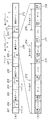
図1は、本実施形態のインクジェット記録装置の概略構成を示すカバーを外した状態の斜視図である。
<Schematic configuration of recording apparatus>
FIG. 1 is a perspective view of a state in which a cover showing a schematic configuration of the ink jet recording apparatus of the present embodiment is removed.
図1において、キャリッジ101は記録ヘッド(不図示)とカートリッジ110を搭載し、ガイド軸102に沿って走行可能である。なお、本実施形態では、記録ヘッドは、インクジェット方式の記録ヘッドである。また、103はシャーシであり、メインシャーシ103aと左右の側面板103b及び103cから構成される。108はキャリッジの駆動源であるキャリッジモータであり、109はキャリッジに接続されキャリッジモータ108によって駆動されるベルト、130は記録ヘッド吐出面の清掃や吸引動作行う回復系ユニット、140はキャリッジ101に搭載された発光素子及び受光素子と共にキャリッジの位置及び速度を算出するCRエンコーダを構成するスケールである。
In FIG. 1, a
記録媒体としての記録紙は、給紙ローラ(不図示)によって装置本体内に送り込まれ、紙送りローラ105とピンチローラ(不図示)、紙押え板(不図示)によって狭持され、記録ヘッドの記録領域へと搬送され記録が行われる。
A recording paper as a recording medium is fed into the apparatus main body by a paper feed roller (not shown), and is nipped by a
インクカートリッジ110は、イエロー、マゼンタ、シアンの3色のインクを収容したカラーインクカートリッジと、ブラックインクを収容したブラックインクカートリッジの2種類で、それぞれ別々にカートリッジガイド7に挿入され、記録ヘッドと接続される。
There are two types of ink cartridges 110: a color ink cartridge containing three colors of yellow, magenta, and cyan, and a black ink cartridge containing black ink. Each
本実施形態のインクジェット記録装置は、ホストコンピュータと接続され、ホストコンピュータ(プリンタドライバ)から記録データの供給を受けて記録を行う。また、本実施形態の記録装置は、記録ヘッドを搭載したキャリッジを記録媒体上で走査させて記録を行うために、記録ヘッドの走査方向の記録領域を複数の領域に分割し、分割された領域単位で画像を記録(印刷)する。 The ink jet recording apparatus according to the present embodiment is connected to a host computer and performs recording upon receiving recording data supplied from the host computer (printer driver). In addition, the recording apparatus of the present embodiment divides the recording area in the scanning direction of the recording head into a plurality of areas in order to perform recording by scanning a carriage on which the recording head is mounted on the recording medium. Records (prints) images in units.
その場合、本実施形態のインクジェット記録装置では、ホストコンピュータ側では、ビット単位のデータ処理により走査方向における記録データ位置の調整(レジスト調整)は行わず、この記録データのレジスト調整は、後述する図2の記録装置側の記録バッファリング構造制御回路8で行う。そのため、ホストコンピュータでの記録データの生成が高速化され、実効的な記録速度の高速化を図ることが可能となる。
In this case, in the inkjet recording apparatus of the present embodiment, the host computer does not adjust the recording data position (registration adjustment) in the scanning direction by the bit-unit data processing, and the registration adjustment of the recording data is described later. 2 is performed by the recording buffering
<記録制御部の構成>
図2は、本発明にかかる記録装置の記録制御部の構成を示すブロック図である。同図に於いて、1はインターフェース信号線S1を介してホストコンピュータ(不図示)から転送されてくるデータを受信し、その受信したデータの中から、記録装置の動作に必要なデータ及び記録データを抽出して一旦蓄えるインターフェース制御部(コントローラ)であり、インターフェースコントローラ1で抽出されたデータは信号線S2を介して受信バッファ2に格納される。
<Configuration of recording control unit>
FIG. 2 is a block diagram showing the configuration of the recording control unit of the recording apparatus according to the present invention. In the figure,
受信バッファ2はSRAMもしくはDRAM等の記憶装置(メモリ)で構成され、この受信バッファに蓄えられるデータは図3A及び3Bで示すような構造のものとなる。
The
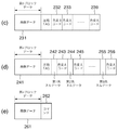
図3Aの(a)において受信バッファのデータ構造が示されるように、左から順に「コマンド」(201)、「データ長」(202)、「設定データ」(203)のデータが格納され、これに続いて「コマンド」(204)、「データ長」(205)、「設定データ」(206)のデータが格納されている。これは時系列順に転送されてきたデータが、受信バッファの連続したアドレスに格納されることを示し、ここで示す設定データ206は、例えば給紙の実行や紙送り量の設定、使用する記録ヘッド数等を示す情報であり、この設定データで定められた情報が全て揃って初めて記録装置で記録が可能となる。この後に、記録の対象となる記録データ(209、212)が受信バッファ2に格納される。
As shown in FIG. 3A (a), the data structure of the reception buffer is stored in the order of “command” (201), “data length” (202), and “setting data” (203). Following this, data of “command” (204), “data length” (205), and “setting data” (206) are stored. This indicates that data transferred in chronological order is stored at consecutive addresses in the reception buffer. The setting
この記録データ(209、212)は、記録ヘッドが記録媒体上を1度の走査で記録する際に必要とされるデータ量を、それより少ないデータ量としてブロック単位に分割したデータであり、そのブロック単位で記録データを区切り、順次第1ブロックデータ(209)、第2ブロックデータ(212)、…として格納される。 The print data (209, 212) is data obtained by dividing the data amount required for the print head to print on the print medium in one scan and divided into blocks as a smaller data amount. The recording data is divided in units of blocks and sequentially stored as first block data (209), second block data (212),.
図3Aの(b)はブロック単位に分割された記録データのデータ構造を詳細に示す図であり、同図で示すように、複数の色のデータ(213〜214)が各々圧縮されたデータとして順次格納される。この圧縮TAG、圧縮データは「色変えコード」(216、217、218)で区切られる。 FIG. 3A (b) is a diagram showing in detail the data structure of the recording data divided into block units. As shown in FIG. 3A, data of a plurality of colors (213 to 214) are respectively compressed data. Stored sequentially. The compressed TAG and the compressed data are delimited by “color changing codes” (216, 217, 218).
例えば、シアン、イエロー、マゼンタ、それと黒の4色の記録データを想定した場合、各色毎に縦64ノズルを1列としたノズル列が走査方向に2列ずつ配列する記録ヘッドを用いると、各ノズル列単位のデータが1つの色の記録データを構成することになるのでノズル2列が4色分、すなわち、圧縮された第1色から第8色の記録データが一つのブロックデータ内に記録データとして格納される。このノズル列の各ノズルは、記録媒体の搬送方向に並んでいる。例えば、第1色と第2色がシアンに対応する記録データ、第3色と第4色はマゼンタに対応する記録データ、第5色と第6色はイエローに対応する記録データ、第7色と第8色は黒に対応する記録データとなる。 For example, when recording data of four colors of cyan, yellow, magenta, and black is assumed, if a recording head in which nozzle rows each having 64 vertical nozzles for each color are arranged in two rows in the scanning direction is used, Since the data for each nozzle row constitutes recording data for one color, the two nozzle rows for four colors, that is, the compressed recording data for the first to eighth colors are recorded in one block data. Stored as data. The nozzles in this nozzle row are arranged in the recording medium conveyance direction. For example, the first color and the second color are recording data corresponding to cyan, the third color and the fourth color are recording data corresponding to magenta, the fifth color and the sixth color are recording data corresponding to yellow, and the seventh color. And the eighth color is recording data corresponding to black.
図4は記録データを保持する記録バッファのデータ構造を示す図である。例えば1回の走査で最大約8インチの走査方向の長さを記録する場合、1つのブロックデータが走査方向に約1インチの記録ができるサイズとすると、トータル8ブロックの記録データを記録すれば、1走査分の画像が完成することになる。第1ブロックから第8ブロックは記録ヘッドの走査方向に配置され、各ブロックデータには、第1色のデータから第8色のデータが格納される。各ブロック内に格納される各色の記録データの長さは記録ヘッドのノズル数に対応するものである。 FIG. 4 shows the data structure of a recording buffer that holds recording data. For example, when a maximum length of about 8 inches in one scan is recorded, if one block data has a size that can record about 1 inch in the scan direction, a total of 8 blocks of record data can be recorded. An image for one scan is completed. The first to eighth blocks are arranged in the scanning direction of the recording head, and the first color data to the eighth color data are stored in each block data. The length of the recording data of each color stored in each block corresponds to the number of nozzles of the recording head.
説明を図2に戻し、各制御ブロックの説明を続ける。受信バッファ2に格納されるデータのうち、記録装置の制御用の設定値である「コマンド」、「データ長」、「設定データ」は、インターフェースコントローラ1から信号線S902を介してCPU9により読み出され、図中にある各部制御回路(7、8)に設定される(S903、S907)。CPU9は読み出したデータ(図3A(a)の201〜208に相当するデータ)を解釈し、その結果に従って記録装置の全体的な記録制御を統括する。一方、CPU9は記録データの処理に関してはデータ解凍ブロック55を起動して処理を実行させるものとする。
Returning to FIG. 2, the description of each control block is continued. Of the data stored in the
データ解凍ブロック55は受信バッファ2から、図3(b)で示されるように「圧縮TAG」と「データ(圧縮データ)」及び「色変えコード」の3種類のデータを読み出し、これらのデータに基づきデータの展開制御を実行する。本実施形態ではデータの圧縮/解凍方法としてPackBits圧縮を用いたので、圧縮TAGが8ビットで00hから7Fhまでの値の場合、非連続なデータが1から128個データ領域に有るとして処理し、圧縮TAGが8ビットでFFhから81hまでの値の場合、次の1バイトデータを連続した2から128個のデータに解凍する処理を行う。なお、データの読出し処理において、80hを読み出した場合は色変えコードとして処理する。解凍したデータを信号線S4aを介して、画像変換ブロック54に送る。この画像変換ブロックにてHV変換がなされ、信号線S4bを介してHV変換されたデータが記録バッファ4に格納される。
The
記録バッファ4には解凍された記録データが図4に示すデータ構造で格納される。記録バッファ4の先頭アドレスには第1ブロックの第1色のデータの先頭データが書き込まれ、その後に続くデータは、アドレスを適宜変更しながら順次書き込まれる。記録バッファのアドレスに一つの色のデータとして格納できる領域は、最初にCPU9が読み込んだ設定データで決定され、その値以上のデータは書き込めないので記録データを圧縮する際には、その設定データに従ったデータサイズの制限が加えられることになる。色変えコードを検出した後のデータは第2色のデータの先頭番地から順次書き込まれる。このアドレスデータの制御は後に説明する記録バッファリング制御構造回路8が実行することになる。
The
この書き込みを第1ブロックの第1色のデータから第8色のデータまで繰り返し、第8色のデータの書き込みを終えて色変えコードを検知すると、第1ブロックのデータが全て書き込み終えたことになる。データ解凍ブロック55はデータの展開動作を終了し、CPU9に対しブロック1個分のデータの展開が完成したことを割込み(S906)で伝え、CPU9からの次のデータ展開の起動を待つ。
This writing is repeated from the first color data of the first block to the eighth color data, and when writing of the eighth color data is completed and the color change code is detected, all the data of the first block has been written. Become. The
記録バッファ4上に複数ブロックの記録データが揃った段階で、CPU9は記録動作を開始すべくキャリッジモータ(図1の108)を動作させ、記録ヘッド6を搭載したキャリッジを走査させながら、記録データをキャリッジエンコーダ(CRエンコーダ)10に同期して転送し、記録することで紙面上(記録媒体に)に画像を完成させることができる。記録ヘッド6が主走査方向に走査した後、搬送手段が記録媒体を副走査方向に搬送する。こうして、記録ヘッドの走査と、記録媒体の搬送を繰り返し行って、1ページ分の画像の記録を行う。
When a plurality of blocks of recording data are prepared on the
記録データ生成ブロック5は、記録バッファ4上に有る記録データの各ブロック構造を、CPU9から指定された値に従って、CRエンコーダ10に同期したタイミングで信号線S5を介して読み出し、記録ヘッド6が記録できるデータ構造に変換しながら信号線S6に出力していく。この記録データ生成ブロック5は後で述べる記録バッファ内のブロック幅(ブロックの長さを示す。)の情報、ブロックの各色の高さ(各色のデータの「ラスター数」という。)についての情報を保持する。
The recording
尚、記録バッファ4から読み出されたデータ領域は次の記録データを蓄えるために、零クリアされる。
The data area read from the
<受信バッファの書き込み、読み込み制御>
以上説明したように受信バッファ2には、インターフェースコントローラ1がデータを書き込み、データ解凍ブロック55が記録データのみを読み出すが、その書き込みアドレスと読み出しアドレスを制御しているのが受信バッファリング構造制御回路7である。受信バッファリング構造制御回路7は受信バッファ2の先頭アドレスと最終アドレス、それと書き込みアドレスと読み出しアドレスの管理を行っている。
<Receiving buffer write / read control>
As described above, the
受信バッファリング構造制御回路7はインターフェースコントローラ1から受信する書き込み要求信号(S701)を受け付け毎に1アドレスずつ加算し、これを書き込みアドレスの情報として受信バッファ2に出力する(S702)。そして、受信バッファリング構造制御回路7は受信バッファ2の最終アドレスに達した場合に書き込みアドレスを受信バッファ2の先頭のアドレスに戻す制御を行う。
The reception buffering
また、書き込みアドレスが読み出しアドレスに到達(一致)した場合、受信バッファ2がデータでいっぱいになり、次のデータを書き込めない旨をインターフェースコントローラ1に信号線S703を介して通信する。
When the write address reaches (matches) the read address, the
このとき同時にCPU9に対しても信号線S904の割込み信号により、受信バッファ2はデータの書き込みができない状態であることを知らせる。受信バッファ2の構造はCPU9が信号線S903のバスを用いて内部のレジスタに書き込むことで設定することができる。
At the same time, the
読み出しアドレスは、CPU9が受信バッファリング構造制御回路7の中に有るデータリード用レジスタを介して直接に受信バッファ2の中のデータを読み出す場合と、データ解凍ブロック55がデータ読み出し要求信号線S705を介して要求した場合に、読み出しアドレスとして信号線S706を介して1アドレスずつ加算されて受信バッファ2に出力される。
When the
受信バッファリング構造制御回路7は読み出しアドレスが最終アドレスに達した場合、読み出しアドレスを受信バッファ2の先頭アドレスに戻す制御を行う。また読み出しアドレスが書き込みアドレスに到達(一致)した場合、受信バッファ上からデータがなくなったので、次のデータを読み出せない旨をデータ解凍ブロックに信号線S704を介して通信する。このとき同時にCPU9に対しても信号線S904の割込み信号線で、受信バッファ2上には、読み出すデータが無い旨を知らせる。
The reception buffering
以上が受信バッファ2に対するデータの書き込み、読み取り制御の処理内容である。次に、この受信バッファ2から読み出され、展開処理されたデータを記録バッファに書き込みし、あるいはその記録バッファからデータを読み取るための処理内容を説明する。
The above is the processing content of the data writing / reading control to the
<記録バッファの書き込み、読み取り制御>
記録バッファ4に対して、画像変換ブロック54が記録データを書き込み、記録データ生成ブロック5がその書き込まれた記録データを読み出すが、その際、書き込みアドレスと読み出しアドレスを制御しているのが記録バッファリング構造制御回路8である。
<Record buffer read / write control>
The
記録バッファリング構造制御回路8は記録バッファの先頭アドレスと、最終アドレス、それと書き込みアドレスと、読み出しアドレスの管理を行っている。
The recording buffering
記録バッファリング構造制御回路8は画像変換ブロック54から受信する書き込み要求信号(S801)を受け付ける毎にアドレスを適宜変更し、これを書き込みアドレスの情報として記録バッファ4に出力する(S802)。そして、記録バッファリング構造制御回路8は記録バッファ4の最終アドレスに達した場合に書き込みアドレスを記録バッファ4の先頭のアドレスに戻す制御を行う。
The recording buffering
また、書き込みアドレスが読み出しアドレスに到達(一致)した場合、記録バッファ4が記録データでいっぱいになり、次の記録データを書き込めない旨を画像変換ブロック54に信号線S809を介して通信する。
When the write address reaches (matches) the read address, the
また、データ解凍ブロック55が色変えコードを受信バッファ2から読み込んだ場合、データ解凍ブロック55は信号線S541を介して画像変換ブロック54にその旨を通信し、画像変換ブロックは、信号線S807を介して、記録バッファリング構造制御回路に出力する。記録バッファリング構造制御回路8は次の色のデータを格納する先頭番地を信号線S802から出力するように準備する。記録バッファ4の構造はCPU9が信号線S907のバスを用いて内部のレジスタに書き込むことで設定することができる。
When the
読み出しアドレスは、記録データ生成ブロック5が各色毎にデータ読み出し要求信号線S805を介して要求すると、読み出しアドレスとして信号線S806を介して1アドレスずつ加算されて記録バッファ4に出力される。
When the recording
記録バッファリング構造制御回路8は読み出しアドレスが最終アドレスに達した場合、読み出しアドレスを記録バッファ4の先頭アドレスに戻す制御を行う。
The recording buffering
記録データ生成ブロック5は現在読み出している記録データブロックのデータ構造をCPU9から信号線S908のバスを介して、記録データ生成ブロック5内部にあるレジスタに設定する。設定された記録データブロック構造内にある記録データを全て読み出すと終了信号S909をCPU9に対し割り込み信号として通信する。この際、記録バッファ4上に次の記録データブロックがすでに展開されているならば、その記録データブロック構造をレジスタに書き込む。
The recording
記録バッファ4は1記録データブロック単位でデータの書き込みを制御しており、書き込まれていない記録データブロックに対し記録データ生成ブロックを起動しないので、記録バッファの読み出しアドレスが書き込みアドレスを越えることは起きない。11は、バッファ構造情報メモリである。これは、記録バッファの制御用の作業用メモリ(ワークRAM)で、後で述べる記録バッファ構造についての情報を一時的に格納する領域である。
The
<記録バッファリング構造制御回路の説明>
記録バッファリング構造制御回路の説明を図5及び図8を用いて説明する。記録バッファリング構造制御回路の処理において、図5は書き込みアドレス制御を中心に説明する図であり、図8は記録バッファリング構造制御回路8の読み出しアドレス制御を中心に説明する図である。
<Description of Recording Buffering Structure Control Circuit>
The recording buffering structure control circuit will be described with reference to FIGS. In the processing of the recording buffering structure control circuit, FIG. 5 is a diagram for explaining mainly the write address control, and FIG. 8 is a diagram for explaining the read address control of the recording buffering
記録バッファリング構造制御回路8は読み出し制御部8Aと書き込みアドレス制御部8Bで構成されている。また、記録バッファ4のバッファ領域は、記録バッファの先頭のアドレスをtop_adrで示し、最終アドレスをbottom_adrで表示する。この先頭アドレスは書き込みアドレス制御部8B内のレジスタ803に格納され、最終アドレスは書き込みアドレス制御部8B内のレジスタ804に格納される。
The recording buffering
記録バッファ4に示される「RP」はリードポインタを示し、「WP」はライトポインタを示す。記録バッファの中のRPとWPの間のハッチング部分は記録データが格納されていることを表している。また、記録バッファ4の白色部分は記録データが格納されていないことを表す。
“RP” shown in the
読み出しアドレス制御部8A内の802は、データの読み出しアドレス(RP:リードポインタ)を示すレジスタである。805から812は第1色から第8色について、各色の情報を格納するレジスタである。ここで、レジスタ805には第1色目データのバッファの高さ情報(1st_hight)と、第1色のデータの有り無しを示す情報(1_color_bit)と、第1色目のレジスト調整値情報(1_reg_wnum)が格納され、同様にレジスタ806〜812についても第2色〜第8色について同様の情報が設定される。
802 in the read
なお、レジスト調整値情報は、ノズル列間のラスタ方向における相対位置に対応した値となるので、1つのノズル列に対しては常に同じ値となる。すなわち、ノズル列毎にレジスト調整値情報を持っている。例えば、第1ノズル列を基準とすると、第1色のデータに対するレジスト調整値情報は0、第2ノズル列と第1ノズル列との距離がAカラム分であれば、第2色のデータに対するレジスト調整値情報はAとなる。また、第3ノズル列と第1ノズル列との距離がBカラム分であれば、第3色のデータに対するレジスト調整値情報はBとなる。このように、第1色のデータを記録する第1ノズル列の位置を基準にして各ノズル列との相対距離に対応して、第2色のデータから第8色のデータのレジスト調整値情報が設定される。 Since the registration adjustment value information is a value corresponding to the relative position in the raster direction between the nozzle rows, it always has the same value for one nozzle row. That is, each nozzle row has registration adjustment value information. For example, when the first nozzle row is used as a reference, the registration adjustment value information for the first color data is 0, and if the distance between the second nozzle row and the first nozzle row is A columns, the second color data The registration adjustment value information is A. If the distance between the third nozzle row and the first nozzle row is B columns, the registration adjustment value information for the third color data is B. Thus, the registration adjustment value information of the second color data to the eighth color data corresponding to the relative distance to each nozzle row with reference to the position of the first nozzle row where the first color data is recorded. Is set.
813はブロックの幅情報(block_width)を設定するレジスタであり、この幅情報は第1色〜第8色までブロック単位で、共通して使われる値である。
上述のブロックの高さ情報、幅情報及びレジスト調整値情報は、図3(a)で説明した設定データに含まれる情報である。 The block height information, width information, and registration adjustment value information described above are information included in the setting data described with reference to FIG.
815は次のブロックデータのアドレスを格納するレジスタであり、このアドレスは各色に関する情報を格納するレジスタ805からレジスタ812のうちのいずれかの値と、ブロックデータに関する幅の情報を格納するレジスタ813の値を用いて決定することができる。書き込み制御部8Bは、書き込み対象となる第1ブロックデータに関する設定情報に従い、次に書き込み対象となる第2ブロックデータの書き込み開始アドレスを決定し、このレジスタに格納する。
A
817はレジスト調整分の書き込み開始アドレスを格納するレジスタであり、このアドレスは各色に関する情報を格納するレジスタ805からレジスタ812のうち全ての値と、ブロックデータに関する幅の情報を格納するレジスタ813の値を用いて決定することができる。書き込み制御部8Bは、書き込み対象となる第1ブロックデータに関する設定情報に従い、次に書き込み対象となるレジスト調整分の書き込み開始アドレスを決定し、このレジスタに格納する。
A
なお、書き込み制御部8Bは、例えば第1色のデータについて説明すると、第1ブロックのデータに対応する記録データの書き込み完了前に、第1ブロックのデータのレジスト調整幅分を反映した第2ブロックでの書き込み開始アドレス情報を決定している。他の色のデータ(第2色のデータ〜第8色のデータ)についても同様である。
For example, the
書き込み制御部8Bは、第1ブロックデータに対応する記録データの書き込み完了前に、第1ブロックデータのレジスト幅分に対する書き込みアドレス情報を、決定した書き込み開始アドレスに更新することができる。
The
また、816はデータの書き込みアドレス(WP)を格納するレジスタである。
814はアドレス制御レジスタで、書き込みアドレス(WP)が読み出しアドレス(RP)を追い越さないように(両アドレスが重複したアドレスを指定しないように)書き込み処理、読み出し処理の管理をする。
<記録バッファへのデータの格納(図6)>
図6は、記録バッファ4に記録データがどのように格納されるか説明する図である。図6(a)では、第1色のデータとして縦に順に4ワード分ずつ、格納される状態を示す。ここで1ワードが16画素分に対応している。レジスタに情報を格納するアドレスは1ずつインクリメントされるものとすると、ライトポインタ(WP)は1→2→3→4→5→…とカウントされる。
<Storage of data in recording buffer (FIG. 6)>
FIG. 6 is a diagram for explaining how recording data is stored in the
例えば、図6(a)のレジスタの設定は、バッファの高さ情報(ラスター数)の値(1st_hight)は「4」であり、データの有り無し情報(1_color_bit)の値は「1(有り)」である。レジスタ813(ブロックの幅情報:block_width)の値は「28」である。 For example, in the register setting of FIG. 6A, the value (1st_hight) of the buffer height information (raster number) is “4” and the value of the data presence / absence information (1_color_bit) is “1 (present)”. It is. The value of the register 813 (block width information: block_width) is “28”.
図6(b)は、第2色のデータがある場合に、記録バッファ4へのデータの書き込みを示す図である。第1色の格納領域に全てデータを格納した後、矢印のようにライトポインタ(WP)を第2色の先頭アドレスへ移動し、第2色のデータの格納を行う。図6(c)では、第2色のデータが無い場合、第1色のデータの格納領域に続き、第3色のデータが格納されることを示す。この場合、図5で示すレジスタ806の第2色のデータの有り無し情報(2_color_bit)は、データ無しを示す「0(無し)」である。あるいは、バッファの高さ情報(2nd_hight)が「0」であれば、データが無いことを示すので、この情報を用いてもかまわない。あるいはデータの有り無し情報とバッファの高さ情報との論理積演算(AND処理)を行ってその結果を用いて判断しても良い。
FIG. 6B is a diagram showing data writing to the
図6(d)では、第2色のデータについて、書き込み位置を示すe1(WP:ライトポインタ)は、読み出し位置を示すe2(RP:リードポインタ)の手前で書き込みを停止することを示す。これは、読み出しが終了していない位置には、データの書き込みを禁止して、上書きをすることを防ぐ制御を行うものである。以上の制御は、第3色から第8色の領域についても同様である。 In FIG. 6D, for the second color data, e1 (WP: write pointer) indicating the writing position indicates that writing stops before e2 (RP: read pointer) indicating the reading position. This is a control for prohibiting overwriting by prohibiting data writing at a position where reading is not completed. The above control is the same for the third to eighth color regions.
<記録バッファへのデータの格納処理>
図9及び10は、レジスト調整値がゼロでない時に、記録バッファ4に記録データがどのように格納されるか説明する図である。図9及び10では、第1色のデータとして縦に順に3ワード分ずつ、格納されている状態を示す。ここで1ワードが16画素分に対応している。
<Storing data in the recording buffer>
FIGS. 9 and 10 are diagrams for explaining how recording data is stored in the
ここで、図9はデータが入力される順番を示し、図10は実際に書き込まれるアドレスを示している図である。 Here, FIG. 9 shows the order in which data is input, and FIG. 10 shows the address to be actually written.
また、図9及び10の斜線部は第1色目のレジスト調整値(6)を示している。実際の書き込み開始位置は図9に示す位置からになるが、実アドレスは図10に示す通り、レジスト調整値に対応してスキップした位置(例えば左から7つ目の24)から始まることになる。 9 and 10 indicate the first color registration adjustment value (6). The actual write start position starts from the position shown in FIG. 9, but the actual address starts from the position skipped corresponding to the registration adjustment value (for example, the seventh 24 from the left) as shown in FIG. .
また、図9及び10の2つの図は対応しているので、例えば1番目に書き込まれるデータのアドレスは、図10に示すように24となり、2番目に書き込まれるデータのアドレスは図10に示すように2Aとなる。 9 and 10 correspond to each other, for example, the address of the first written data is 24 as shown in FIG. 10, and the address of the second written data is shown in FIG. It becomes 2A.
ここで、図9及び10のレジスタの設定は、バッファの高さ情報(ラスター数)の値(1st_hight)は「3」であり、データの有り無し情報の値(1_color_bit)は「1(有り)」である。レジスタ813(ブロックの幅情報:block_width)の値は「16」である。第1色目のレジスト調整値(1_reg_wnum)は6で第2色目のレジスト調整値(2_reg_wnum)は3である。 9 and 10, the buffer height information (raster number) value (1st_hight) is “3”, and the data presence / absence information value (1_color_bit) is “1 (present)”. It is. The value of the register 813 (block width information: block_width) is “16”. The first color registration adjustment value (1_reg_wnum) is 6, and the second color registration adjustment value (2_reg_wnum) is 3.
この時、例えば図9において、レジスタに情報を格納するアドレスを右に1ずつインクリメントすると、図10においてライトポインタ(WP)の実アドレスは0→6→C→12→18→…とカウントアップされることになる。 At this time, for example, in FIG. 9, if the address for storing information in the register is incremented by 1 to the right, the actual address of the write pointer (WP) is counted up from 0 → 6 → C → 12 → 18 →. Will be.
ここで、データを書き込む順番は、図9及び図10の様に16個単位で一つ下の段に行っても構わないし、データを受信する順序により、ブロック幅まで進んで後(10個単位)一つ下の段に移っても構わない(図9で、10の位置の次に17の位置に進む)。 Here, the order in which data is written may be one step lower in increments of 16 as shown in FIGS. 9 and 10, and after the data has been advanced to the block width (in increments of 10 increments). ) You may move to the next lower level (in FIG. 9, proceed to position 17 after position 10).
また、図9に示す通りに、第1色のデータについて、10個目までデータが書き込まれた(格納された)後、11個目のデータを書き込む先は、次のブロック(第2ブロック)の先頭になる。これはレジスト調整を行うことによって、現在のブロック(第1ブロック)に入りきらなくなったデータを書き込む(格納する)ためである。ここでは、第2ブロックの先頭に格納されるデータが11個目のデータであることは、レジスタ813の値「16」とレジスタ805のレジスト調整値「6」から、16−6+1=11より求められる。データを格納するカウンタを設け、そのカウンタが10になれば、第2ブロックの先頭のアドレスを指定する構成にすればよい。
Further, as shown in FIG. 9, after the first color data is written (stored) up to the tenth data, the eleventh data is written to the next block (second block). It becomes the head of. This is because the data that can no longer fit in the current block (first block) is written (stored) by performing registration adjustment. Here, the fact that the data stored at the head of the second block is the eleventh data is obtained from 16−6 + 1 = 11 from the value “16” of the
なお、図9において、第1色のデータの11個目のデータが格納されるアドレスは、第1ブロックに格納される色の数(2)と各色の高さ(3)、ブロックの幅(16)に基づいて求められる。 In FIG. 9, the address where the eleventh data of the first color data is stored is the number of colors stored in the first block (2), the height of each color (3), and the block width ( 16).
レジスト調整分の書き込みが終了(図9で16番目のデータ書き込みが終了)すると、17個目のデータは、現在のブロック(第1ブロック)から書かれることになる。これは実際のアドレスが図10で16個目がDEで、17個目が26になると言うことである。 When the registration adjustment writing ends (the 16th data writing in FIG. 9 ends), the 17th data is written from the current block (first block). This means that the actual address in FIG. 10 is 16th DE and 17th is 26.
この様にして、現在のブロック(第1ブロック)と次のブロック(第2ブロック)との間を行き来することで、レジスト調整を行いながら、第1色目のデータを書き込んでいく。 In this manner, the first color data is written while performing registration adjustment by going back and forth between the current block (first block) and the next block (second block).
第1色目のデータが全て書き終わると、同様の処理を第1ブロックの第2色目以降に行っていく。 When all the data of the first color is written, the same processing is performed after the second color of the first block.
また、レジスタに情報を格納するアドレスは、図6のように縦に1ずつインクリメントさせて、ライトポインタ(WP)の実アドレスを0→2→4→6→8→…とカウントアップさせてもよい。 Further, the address for storing information in the register may be incremented vertically by 1 as shown in FIG. 6 and the real address of the write pointer (WP) may be counted up as 0 → 2 → 4 → 6 → 8 →. Good.
ここで、図9においてレジスタに情報を格納するアドレスを縦に1ずつインクリメントさせないのは、画像変換ブロック3からのデータや、ホストからのデータの変更に柔軟に対応するためである。
Here, the reason why the address for storing information in the register in FIG. 9 is not incremented by 1 is to flexibly cope with changes in data from the
例えば、画像変換ブロック3を使用しない時には、ホストからの記録データは、従来通りレジスタに情報を格納するアドレスは図6Aのように1ずつインクリメントさせて、ライトポインタ(WP)は1→2→3→4→5→…とカウントするように対応している。
For example, when the
しかし、画像変換ブロック3を使用して例えばHV変換等を行うと、HV変換を行った後の記録記録データは、レジスタに情報を格納するアドレスは図6のように1ずつインクリメントさせて、ライトポインタ(WP)を1→2→3→4→5→…とカウントアップする事が出来なくなる。
However, when, for example, HV conversion or the like is performed using the
その為、アドレスのインクリメント量に自由度を持たせることで、ホストからの様々なデータ転送方式にも対応でき、また画像変換ブロック3でのデータ変換にも対応することが出来るようになる。
Therefore, by giving a degree of freedom to the increment amount of the address, it is possible to cope with various data transfer methods from the host and also to cope with data conversion in the
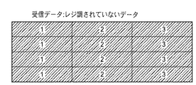
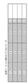
図11A、図11B、図11Cは、レジスト調整に関連したデータの状態を模式的に示す図である。図中の数字はいずれもブロック番号を示している。図11Aは、従来例のようにホストコンピュータ(プリンタドライバ)で全てのレジスト調整を行った場合の転送データを示している。図11Bは、本実施形態でホストコンピュータから送信され記録装置が受信したデータを示している。このデータはレジスト調整は行われていない。図11Cは、図11Bのようなデータに対して記録装置側でレジスト調整され、記録装置(インクジェット記録装置)に設けられている記録バッファ4に格納された状態を示している。
11A, 11B, and 11C are diagrams schematically illustrating data states related to registration adjustment. Each number in the figure indicates a block number. FIG. 11A shows transfer data when all registration adjustments are performed by the host computer (printer driver) as in the conventional example. FIG. 11B shows data transmitted from the host computer and received by the recording apparatus in this embodiment. This data has not undergone registration adjustment. FIG. 11C shows a state in which registration as to the data shown in FIG. 11B is adjusted on the recording apparatus side and stored in the
図11Aと図11Cに示されたデータを記録媒体へ記録すると、いずれもレジスト調整がなされているため同様な記録結果となるが、図11Cのデータは図11Bの受信データに対して記録装置側でレジスト調整を行ったため、レジスト調整データにより、ラスタ方向(図11Aから11Cにおける左右の方向)に記録データの格納される位置がずれ、その結果として図11Bのデータよりもブロック数が1つ増えている。 When the data shown in FIG. 11A and FIG. 11C are recorded on the recording medium, the registration is adjusted and the recording result is the same. However, the data in FIG. Since the registration adjustment is performed, the position where the recording data is stored is shifted in the raster direction (the left and right directions in FIGS. 11A to 11C) due to the registration adjustment data. ing.
このようにホストコンピュータから送信したブロック数と記録装置の記録バッファに書き込まれたブロック数が異なると、論理的な矛盾が生じてしまう。これは、ホストコンピュータから送信したブロック数に基づいて、ホストコンピュータから記録装置に対して記録幅(走査方向)に関する情報を出力するからである。記録装置は、この情報に基づいて記録動作を行うので、ブロック数について異なる量だけ記録がなされない。例えば、ホストコンピュータから記録装置に3ブロック分の記録データを出力し、記録装置は、レジスト調整を行って4ブロックに記録データを格納した場合、記録は3ブロック分しかなされず、1ブロックが記録されないのである。 Thus, if the number of blocks transmitted from the host computer and the number of blocks written in the recording buffer of the recording apparatus are different, a logical contradiction occurs. This is because information on the recording width (scanning direction) is output from the host computer to the recording apparatus based on the number of blocks transmitted from the host computer. Since the recording apparatus performs a recording operation based on this information, recording is not performed by a different amount with respect to the number of blocks. For example, when recording data for 3 blocks is output from the host computer to the recording apparatus, and the recording apparatus performs registration adjustment and stores the recording data in 4 blocks, the recording is performed only for 3 blocks, and 1 block is recorded. It is not done.
本実施形態では、この様な矛盾が生じないように、図11Bに示すようなデータをホストコンピュータから転送する場合、1ブロック余分なデータを付加して記録装置に送信し、ホストコンピュータと記録装置(記録バッファ)とのブロック数が同じとなるようにする。 In this embodiment, when transferring data as shown in FIG. 11B from the host computer so as not to cause such a contradiction, one block extra data is added and transmitted to the recording device, and the host computer and the recording device are transmitted. (Record buffer) and the number of blocks should be the same.
図12A、図12B、図12Cは、本実施形態におけるレジスト調整に関連したデータの状態を、図11A〜図11Cと同様に示す図である。図12Aは、従来例のようにホストコンピュータ(プリンタドライバ)で全てのレジスト調整を行った場合の転送データを示しており、図11Aと同様な構成となる。図12Bは、本実施形態でホストコンピュータから送信され記録装置が受信したデータを示している。しかし、このデータに対してはレジスト調整は行われていない。図12Cは、図12Bのようなデータに対して記録装置側でレジスト調整され、記録バッファに格納された状態を示している。 FIGS. 12A, 12B, and 12C are views showing data states related to registration adjustment in the present embodiment, as in FIGS. 11A to 11C. FIG. 12A shows transfer data when all registration adjustments are performed by the host computer (printer driver) as in the conventional example, and has the same configuration as FIG. 11A. FIG. 12B shows data transmitted from the host computer and received by the recording apparatus in this embodiment. However, no registration adjustment is performed on this data. FIG. 12C shows a state where registration is adjusted on the recording apparatus side for the data as shown in FIG. 12B and stored in the recording buffer.
ここで、図11B及び図11Cに示したデータと、図12B及び図12Cに示したデータとを比較すると、図11Bの受信データに対してレジスト調整を行った図11Cのデータのブロック数は1つ増えているが、図12Bの受信データに対してレジスト調整を行った図12Cのデータのブロック数は増えていないことがわかる。ずなわち、ホストコンピュータから図12Bのようなデータを転送する場合には、1ブロック余分に送信する必要はない。 Here, comparing the data shown in FIG. 11B and FIG. 11C with the data shown in FIG. 12B and FIG. 12C, the number of blocks of the data of FIG. It can be seen that the number of blocks in the data in FIG. 12C in which registration adjustment is performed on the received data in FIG. 12B has not increased. In other words, when transferring data as shown in FIG. 12B from the host computer, it is not necessary to transmit one block extra.
図11B及び図11Cに関連して、1ブロック余分に転送する場合についてもう少し詳しく説明する。図13Aは、1ブロック余分に転送する場合のデータ構成を示す図である。この場合、留意すべきは1ブロックのサイズ(走査方向のブロックサイズ)と、転送される記録データの最後のブロックについてのデータ量(図11B及び11Cでは3つめのブロックについての走査方向のデータサイズ、図12では4つめのブロックについての走査方向のデータサイズ)、レジスト調整量(例えばカラム単位の値)の関係である。 With reference to FIG. 11B and FIG. 11C, the case of transferring one extra block will be described in a little more detail. FIG. 13A is a diagram showing a data configuration in the case of transferring an extra 1 block. In this case, it should be noted that the size of one block (block size in the scanning direction) and the data amount for the last block of print data to be transferred (data size in the scanning direction for the third block in FIGS. 11B and 11C). FIG. 12 shows the relationship between the data size in the scanning direction for the fourth block) and the registration adjustment amount (for example, a value in column units).
例えば、
走査方向のブロックサイズ<走査方向のデータサイズ+レジスト調整量
であれば、図11Cに示すように、ブロック数を1つ増やす必要がある。
For example,
If the block size in the scanning direction <data size in the scanning direction + registration adjustment amount, as shown in FIG. 11C, the number of blocks needs to be increased by one.
一方、
走査方向のブロックサイズ>走査方向のデータサイズ+レジスト調整量
であれば、図12Cに示すように、ブロック数を増やす必要はない。
on the other hand,
If the block size in the scanning direction> the data size in the scanning direction + the registration adjustment amount, as shown in FIG. 12C, it is not necessary to increase the number of blocks.
このように、ホストコンピュータにおいて、走査方向のデータサイズとレジスト調整量の和が走査方向のブロックサイズより大きくなるか否かを判断し、この判断結果に応じて、ブロック数を増やす処理を行う。 As described above, in the host computer, it is determined whether or not the sum of the data size in the scanning direction and the registration adjustment amount is larger than the block size in the scanning direction, and processing for increasing the number of blocks is performed according to the determination result.
ここで、図14は、ホストコンピュータ1401と記録装置1402の概略制御構成を示す図である。
Here, FIG. 14 is a diagram showing a schematic control configuration of the
ホストコンピュータ1401から記録装置1402へ記録データがインターフェース1405を介して転送される。
Recording data is transferred from the
ホストコンピュータ1401においてなされる処理の一例を以下に述べる。記録データを生成するプリンタドライバーはCPU1403により実行される。そして、これらの記録データはブロック単位で生成された後、所定の圧縮方法で圧縮され、記録装置1402に対して出力処理を行う。
An example of processing performed in the
記憶手段1404は、生成した記録データ、あるいは圧縮されたデータを一時的に保存するために用いられる。また、記憶手段1404には生成した記録データのブロック数(データ量)の数を保持するカウンタを備えている。
The
このCPU1403は、上述したように、走査方向のデータサイズとレジスト調整量の和が走査方向のブロックサイズより大きくなるか否かを判断し、この判断結果に応じて、ブロック数を増やす処理を行う。このため、CPU1403は予め、走査方向のブロックサイズ、レジスト調整量についての情報を記録装置から取得する。
As described above, the
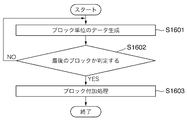
図16は、データ生成についての処理を示すフローチャートである。ステップS1601において、ブロック単位でデータを生成する。ブロック単位のデータを生成するたびに、生成するブロック数をカウントする。そして、ステップS1602において、最後のブロック(記録ヘッドの走査方向の最も下流のブロック)であるか否かを判定する。もし最後のブロックであればS1603にて、ブロック付加処理を行う。このブロック付加処理は図15において説明する。図16で述べた処理は、走査毎に走査方向のデータ量は異なるので、走査毎に行なわれる。 FIG. 16 is a flowchart showing processing for data generation. In step S1601, data is generated in units of blocks. Each time data in units of blocks is generated, the number of blocks to be generated is counted. In step S1602, it is determined whether it is the last block (the most downstream block in the scanning direction of the recording head). If it is the last block, block addition processing is performed in S1603. This block addition processing will be described with reference to FIG. The processing described in FIG. 16 is performed for each scan because the amount of data in the scan direction differs for each scan.
そして、1走査の記録幅についての情報を前もって取得することで、記録する生成ブロックの数が得られ、この数がS1602の判断の閾値として使われる。 The number of generated blocks to be recorded is obtained by acquiring in advance information about the recording width of one scan, and this number is used as the threshold for determination in S1602.
その処理について図15のフローチャートを用いて詳細に説明する。ステップS1501において、レジスト調整量の情報とブロックサイズ(主走査方向)について情報を取得する。ステップS1502において、最後のブロックに格納されるデータサイズ(走査方向のデータサイズ)を取得する。ステップS1503において、最後のブロックについてのデータサイズ(走査方向)とレジスト調整量の情報との和と走査方向のブロックサイズとを比較する。なお、ここで、データサイズ、レジスト調整量の情報、ブロックサイズは例えばカラム数である。 The process will be described in detail with reference to the flowchart of FIG. In step S1501, information on registration adjustment amount and block size (main scanning direction) are acquired. In step S1502, the data size (data size in the scanning direction) stored in the last block is acquired. In step S1503, the sum of the data size (scanning direction) and registration adjustment amount information for the last block is compared with the block size in the scanning direction. Here, the data size, registration adjustment amount information, and block size are, for example, the number of columns.
そして、ステップS1503において、走査方向のブロックサイズの方が小さければ(NO)、ステップS1504においてブロックを1つ追加する。走査方向のブロックサイズの方が大きければ(YES)、終了する。 In step S1503, if the block size in the scanning direction is smaller (NO), one block is added in step S1504. If the block size in the scanning direction is larger (YES), the process ends.
なお、この判断は、各色に対応する記録データについて行う。これは、走査方向のブロックサイズは各色について同じであるが、レジスト調整量と最後のブロックについての走査方向のデータサイズは色毎に異なる場合があるからである。そして、1色でもブロックを追加する必要があれば、他の色についてもブロックの追加を行う。 This determination is made for the recording data corresponding to each color. This is because the block size in the scanning direction is the same for each color, but the registration adjustment amount and the data size in the scanning direction for the last block may be different for each color. If it is necessary to add a block even for one color, a block is also added for another color.
次に、各ブロックのデータに付加される色変えコードに説明する。上記で図3Aの(b)に関連して説明したが、記録データの区切りを判別するために、各ブロックに色変えコードが挿入されている。 Next, the color change code added to the data of each block will be described. As described above with reference to FIG. 3A (b), a color change code is inserted into each block in order to determine the delimiter of the recording data.
そして、図3Aの(b)に示すように1つの色についての情報として、圧縮TAGや圧縮されたデータで構成されている。そして、色変えコードは、これらのデータの後に付加されている。 Then, as shown in FIG. 3A (b), the information about one color is composed of a compressed TAG and compressed data. The color change code is added after these data.
しかし、ステップS1504でブロックを付加する場合には、これらの圧縮TAGや圧縮されたデータはなく、色変えコード(232、233、239)のみが最後のブロック(第nブロックデータ)231に続いて付加される。ここでは、色数は8であるので、8つの色変えコードが付加されてる。図3Bの(c)は、このコードを受信した場合の第nブロックデータ以降の状態を示す図である。 However, when adding a block in step S1504, there is no compressed TAG or compressed data, and only the color change code (232, 233, 239) follows the last block (nth block data) 231. Added. Here, since the number of colors is 8, eight color changing codes are added. FIG. 3B (c) is a diagram showing a state after the nth block data when this code is received.
これにより、記録装置は、色変えコードのみが付加されているので、記録装置はレジスト調整のために記録データがブロックからはみ出すために、ブロックが付加して格納する処理を行う指示であることを認識(判断)でき、記録バッファにレジスト調整量に基づいて記録データを格納する。 As a result, since only the color change code is added to the recording apparatus, the recording apparatus is instructed to perform processing to add and store the recording data so that the recording data protrudes from the block for registration adjustment. The recording data is stored in the recording buffer based on the registration adjustment amount.
なお、ブロックを付加する場合の他の例として、図3Bの(d)に示すように例えば色毎に1バイトのヌルデータ(242、244、…、255)のみを含み、このヌルデータに色変えコード(243、245、…、256)が付加する形態でも構わない。これにより、記録装置は、圧縮TAGが含まれず1バイトのヌルデータのみで構成されていることで、ブロックが付加する指示があることを容易に認識できる。 As another example of adding a block, as shown in FIG. 3B (d), for example, only one byte of null data (242, 244,..., 255) is included for each color, and the color change code is included in this null data. (243, 245,..., 256) may be added. As a result, the recording apparatus can easily recognize that there is an instruction to be added by the block because it includes only 1-byte null data without including the compressed TAG.
あるいは、色変えコードを付加するのではなく、図3Bの(e)に示すように最後のブロックデータ(第nブロック)261の後にブロックの付加の指示を示すコマンド262を追加してもかまない。
Alternatively, instead of adding a color change code, a
次に、上述したブロックを付加する場合についてホストコンピュータにおける記録データの格納処理についての補足説明を行う。図13Aにおいて、(a)は圧縮前のデータを示し、(b)は圧縮前のデータにレジスト調整幅を加えた状態を示し、(c)は増えたブロックの後端を基準としたレジスト調整幅を示し、(d)は最後の記録データが格納されるべき位置を示している。なお、(b)のブロックは第nブロック、(c)のブロックは第n+1ブロックとする。 Next, a supplementary explanation will be given for recording data storage processing in the host computer when adding the above-described blocks. In FIG. 13A, (a) shows data before compression, (b) shows a state in which a registration adjustment width is added to data before compression, and (c) shows registration adjustment based on the rear end of the increased block. The width indicates the position, and (d) indicates the position where the last recorded data is to be stored. The block (b) is the nth block, and the block (c) is the (n + 1) th block.
この場合、最後の記録データの位置は、(d)のクロスハッチングした領域にある必要がある。図3Bの(d)を用いて説明した場合は、このクロスハッチングした領域にある。これは、(d)の斜線部分の領域に最後の記録データが格納されると、レジスト調整することによってブロックが更に1つ増えてしまうからである。 In this case, the position of the last recording data needs to be in the cross-hatched area of (d). In the case described with reference to FIG. 3B (d), it is in this cross-hatched area. This is because when the last recording data is stored in the shaded area of (d), the number of blocks is further increased by registration adjustment.
図13Bも図13Aと同様に、(a)は圧縮前のデータを示し、(b)は圧縮前のデータにレジスト調整幅を加えた状態を示し、(c)は増えたブロックの後端を基準としたレジスト調整幅を示し、(d)は色変えコード(COL_CNG)が挿入されるべき位置を示している。図13Aと異なるのは、1ブロック余分に転送しない点である。 Similarly to FIG. 13A, FIG. 13B shows data before compression, (b) shows a state in which the registration adjustment width is added to the data before compression, and (c) shows the rear end of the increased block. The reference registration adjustment width is shown, and (d) shows the position where the color change code (COL_CNG) should be inserted. The difference from FIG. 13A is that one extra block is not transferred.
この場合にも、(d)のクロスハッチングされた領域以外に最後の記録データが格納されていると、レジスト調整することによって1ブロック増えてしまうため、色変えコードの位置は、(d)に示すように、(c)に示された後端を基準にしたレジスト調整幅の境界より前にある必要がある。 Also in this case, if the last recorded data is stored in the area other than the cross-hatched area of (d), the registration change will increase one block, so the position of the color change code is (d). As shown, it must be before the boundary of the resist adjustment width based on the rear end shown in (c).
図7を参照して、レジスト調整を行う必要がない場合における記録データの格納について説明する。 With reference to FIG. 7, recording data storage when registration adjustment is not required will be described.
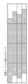
図7の(a)は、記録バッファに書き込まれた1回の走査(スキャン)に対応した記録データの例を示す図である。図示した例では第4ブロックに対応する領域に画像データがなく、記録バッファには第4ブロックは確保されていない。 FIG. 7A is a diagram showing an example of print data corresponding to one scan written in the print buffer. In the illustrated example, there is no image data in the area corresponding to the fourth block, and the fourth block is not secured in the recording buffer.
また、図7(a)で、第2ブロックに格納されるデータには第3色のデータ及び第4色のデータはないので、これらの分をつめて第5色のデータ〜第8色のデータが格納されている。第3ブロックには、第1色のデータ、第2色のデータのみが格納され、第3色以降のデータは格納されていない。第2ブロックと第3ブロックのハッチングされたは部分は、データが無いためにバッファの割り当てがされていないことを示す。従って、第2ブロックにおける第8色のデータの最終アドレスの次のアドレスは、第3ブロックにおける第1色のデータの先頭アドレスである。このように、レジスト調整を行う必要がない場合には、画像データを詰めて記録バッファに格納することができるので、記録バッファを効率良く使用することができる。 In FIG. 7A, since the data stored in the second block does not include the third color data and the fourth color data, the data of the fifth color to the eighth color are collected together. Data is stored. In the third block, only the data for the first color and the data for the second color are stored, and the data for the third color and thereafter are not stored. The hatched portions of the second block and the third block indicate that no buffer is allocated because there is no data. Accordingly, the next address after the final address of the eighth color data in the second block is the first address of the first color data in the third block. Thus, when it is not necessary to perform registration adjustment, the image data can be packed and stored in the recording buffer, so that the recording buffer can be used efficiently.
従って、例えば、記録データが無い領域に対しても記録バッファの領域を一律に格納した場合に記録バッファに1走査分のデータすべてを格納する領域を確保できない場合でも、画像データの有無をレジスタに格納されている色のデータの有無の情報に基づきデータの格納を制御することで1走査分のデータを格納することができる。 Therefore, for example, even if the recording buffer area is uniformly stored even in the area where there is no recording data, even if the area for storing all the data for one scan cannot be secured in the recording buffer, the presence or absence of image data is stored in the register. Data for one scan can be stored by controlling the storage of data based on the information on the presence or absence of stored color data.
<記録バッファからのデータの読み出し>
以下に、図8を参照して記録バッファからのデータの読み出し処理について説明する。図8において、左側は記録バッファリング構造制御回路8の読み出しアドレス制御部8Aを示し、右側は記録バッファ4を示している。
<Reading data from the recording buffer>
Hereinafter, a process of reading data from the recording buffer will be described with reference to FIG. In FIG. 8, the left side shows the read
記録バッファ4のバッファ領域は、記録バッファの先頭のアドレスであるtop_adrで表され、最終アドレスはbottom_adrで表される。この先頭アドレスはレジスタ803に格納され、最終アドレスはレジスタ804に格納される。記録バッファに示される「RP」は図5と同様にリードポインタであり、「WP」はライトポインタである。記録バッファ4におけるRPとWPの間のハッチング部分は記録データが格納されていることを表し、それ以外の部分は記録データが格納されていないことを表す。
The buffer area of the
読み出しアドレス制御部8A内の802は、データの読み出しアドレス(RP:リードポインタ)を示すレジスタであり、破線の枠で囲った900は第1レジスタ群、実線の枠で囲った901は第2レジスタ群である。
第1ブロックから第8ブロックの記録データを記録する場合、例えば、走査の開始時において、第1レジスタ群には第1ブロックについての情報が格納されている。また、第2レジスタ群には、第2ブロックについての情報が格納される。第1ブロックの記録が終了すると、第1レジスタ群900には第2レジスタ群901の情報がコピーされて格納される。そして第2レジスタ群901には、第3ブロックの情報が格納される。以下、最後の第8ブロックのデータが格納されるまで同様の処理が順に行われる。そして、次の走査開始時には、再び、第1レジスタ群には第1ブロックの情報が格納され、第2レジスタ群には第2ブロックの情報が格納される。
When recording data from the first block to the eighth block, for example, at the start of scanning, information about the first block is stored in the first register group. The second register group stores information about the second block. When the recording of the first block is completed, the information of the
第1レジスタ群が示す第nブロックの記録が終了した時、第2レジスタ群に第n+1ブロックの情報が格納されていない場合は、第n+1ブロックの記録データがまだ準備できていないので、第2レジスタ群の情報は第1レジスタ群にコピーされず、加えて記録バッファからのデータ読み出しを停止する。 When the recording of the n + 1-th block indicated by the first register group is finished and the information of the (n + 1) -th block is not stored in the second register group, the recording data of the (n + 1) -th block has not been prepared yet. The register group information is not copied to the first register group, and in addition, data reading from the recording buffer is stopped.
第1レジスタ群内にあるレジスタ819は、第1色についての高さ情報(1st_hight)と色のデータの有り無し情報(1_color_bit)を設定するレジスタである。各レジスタ822、824、826、828、830、832、834は第2色〜第8色について同様に高さ情報と色のデータの有り無し情報を設定するレジスタである。
A register 819 in the first register group is a register for setting height information (1st_hight) for the first color and presence / absence information (1_color_bit) of color data. The
820は各ブロックデータの幅情報(block_width)を格納するレジスタである。この幅情報は第1色〜第8色までブロック単位で、共通して使われる値である。 A register 820 stores width information (block_width) of each block data. This width information is a value that is commonly used in units of blocks from the first color to the eighth color.
レジスタ818は第1色の読み出しアドレス(1st_color_adr)を格納するレジスタである。第1色のデータが格納されている記録バッファ819から読み出されるとアドレスが更新される。例えば図9に示すように、第1色のデータの内、1→2→3→4と1カラム分のデータが読み出される。レジスタ821、823、825、827、829、831、833はそれぞれ第2色〜第8色の読み出しアドレスを格納するレジスタであり、第2色〜第8色のデータも第1色のデータと同様に順に1カラム分のデータが読み出される。
The
記録バッファ4に格納されるデータは複数の色のデータを含むため、例えば、第1色、第2色、…のデータが混在した場合、各色単位のデータを格納するためのアドレスは、連続していないものとなる。そのため、読み出しアドレスのレジスタが1つであれば、例えば第1色の記録バッファ4のアドレスの次に第2色の記録バッファ1のアドレス読み出しを行う際、アドレス計算をする必要があるが、記録バッファ4に各色ごとに読み出しアドレスを格納するレジスタを用意することで、カラム単位での読み出しを行う際のアドレス計算を省くことができる。
Since the data stored in the
817はアドレス制御レジスタである。読み出しアドレスは、記録データ生成ブロック5が各色毎にデータ読み出し要求信号線S805を介して要求すると、アドレス制御レジスタ817は読み出しアドレスとして信号線S806を介して1アドレスずつ加算して記録バッファ4に出力する。
835は次のブロックのアドレスを格納するレジスタである。現在読み出されているブロックが第1ブロックであれば、このレジスタには第2ブロックの先頭のアドレスが格納される。このレジスタの値は、現在読み出されているブロックデータの読み出しが終了すると、レジスタ802にコピーされる。これにより、次のブロックデータの読み出しがスムーズにできる。
A register 835 stores the address of the next block. If the block currently being read is the first block, this register stores the start address of the second block. The value of this register is copied to the
レジスタ836は第1色から第8色のうち、読み出す順序を特定するための情報を格納するテーブルである。このテーブルに設定された値によって記録バッファからデータを読み出す順序を自由に設定することができる。例えば、第1色→第2色→…→第8色の順に読み出すことができる。また、値を変えて、第1色→第2色→第5色→第6色→第7色→第8色のように第3色、第4色のデータの読み出しをスキップすることもできる。これによって、格納されていない色の記録データについては、正確に読みとばすことができる。 The register 836 is a table that stores information for specifying the reading order among the first to eighth colors. The order of reading data from the recording buffer can be freely set by the values set in this table. For example, it is possible to read in the order of the first color → the second color →... → the eighth color. It is also possible to change the value and skip reading of the data of the third color and the fourth color, such as 1st color → 2nd color → 5th color → 6th color → 7th color → 8th color. . As a result, it is possible to accurately skip the recorded data of colors that are not stored.
第2レジスタ群901は次のブロックデータに関する情報を格納するバッファの集まりである。第1レジスタ群の各レジスタが読まれたら、第2レジスタ群の各レジスタに設定されている値が、第1レジスタ群の対応するレジスタに設定される。例えば、レジスタ838に設定されている値がレジスタ819に設定される。レジスタ839〜845は、次のブロックデータにおける第2色〜第8色のデータについて同様の情報が設定されるレジスタである。
The
レジスタ838(819)には第1色目のデータのバッファの高さ情報と、第1色のデータの有り無しを示す情報が格納される。 The register 838 (819) stores buffer height information for the first color data and information indicating the presence or absence of the first color data.
846(820)はブロックの幅情報を設定するレジスタである。この幅情報は第1色〜第8色までブロック単位で、共通して使われる値である。 846 (820) is a register for setting block width information. This width information is a value that is commonly used in units of blocks from the first color to the eighth color.
レジスタ878は、先に設定したブロックのサイズとブロックのサイズが同じであるか否かを表す情報(same_type)を格納するレジスタであり、ブロックのサイズが同じ場合、この値を「1」とすることで、第1レジスタ群に同じ値を容易に再設定することができる。この場合、レジスタ838〜846の設定を省くことができる。一方、レジスタ878の値が「0」の場合には、各レジスタ838〜846にそれぞれの値が設定される。
The
以上説明したように好適な一実施形態によればインクジェット記録装置において、記録ヘッドの走査方向におけるレジスト調整を行う機能を記録装置側に持たせることで、ホストコンピュータでの記録データの生成を高速化することができ、ホストコンピュータで記録が指示されてから記録装置が記録を実行するまでの時間を短縮することができる。 As described above, according to a preferred embodiment, in the ink jet recording apparatus, the recording apparatus side has a function of performing registration adjustment in the scanning direction of the recording head, thereby speeding up the generation of recording data in the host computer. It is possible to shorten the time from when the recording is instructed by the host computer to when the recording apparatus executes the recording.
<変形例>
上記の実施形態では、各色のブロックはいずれも同じ幅であったが、ブロック毎に異なった幅を設定しても良い。
<Modification>
In the above embodiment, each color block has the same width, but a different width may be set for each block.
図7の(b)は、上記の実施形態における図7の(a)より、更にメモリを有効に使う場合を説明した図である。図7(a)では、記録領域を複数に分割した各ブロックの走査方向の幅情報はどのブロックも等しかったが、ブロック内に記録するべき画像データが無い場合は、必要最低限の幅情報を持てばよい。例えば、図7(a)の第3ブロックと第5ブロックのデータ量が他のブロックよりも少ないと想定すると、第3ブロックと第5ブロックの幅を、記録データの量に応じて短くすることができる。 FIG. 7B illustrates a case where the memory is used more effectively than in FIG. 7A in the above embodiment. In FIG. 7A, the width information in the scanning direction of each block obtained by dividing the recording area into a plurality of blocks was equal to each other. Just hold it. For example, assuming that the amount of data in the third block and the fifth block in FIG. 7A is smaller than the other blocks, the widths of the third block and the fifth block are shortened according to the amount of recording data. Can do.
この場合、本変形例においては、幅がフルサイズのブロックとその半分のサイズのブロックとの2つのサイズのブロックを用いて制御する。幅が半分のサイズのブロックは色変えコードを区切りとして使用し、フルサイズのブロックは所定長であるので、色変えコードを使用しない。つまり、受信バッファのデータを記録バッファに書き込む(転送する)際に、色変えコードが半分のブロックサイズを超えても現れない場合は、フルサイズのブロックであると認識する。本例では、第3ブロックと第5ブロックの幅を、記録データ量に応じて、他のブロックの幅の半分とした。 In this case, in the present modification, control is performed using two size blocks, a full-size block and a half-size block. The half-width block uses the color change code as a delimiter, and the full-size block has a predetermined length, so no color change code is used. That is, when the data in the reception buffer is written (transferred) to the recording buffer, if the color change code does not appear even if it exceeds the half block size, it is recognized as a full size block. In this example, the widths of the third block and the fifth block are set to half of the widths of the other blocks according to the recording data amount.
これによって、メモリ容量が少ない場合にも、記録バッファを効率良く使うことができる。例えば、記録バッファが1走査分のデータすべてを格納する領域を確保できない場合でも、1走査分のデータを格納することができる。 As a result, the recording buffer can be used efficiently even when the memory capacity is small. For example, even when the recording buffer cannot secure an area for storing all the data for one scan, the data for one scan can be stored.
なお、この場合、ホスト装置側で、記録データが複数ブロックにまたがってヌルデータが続く場合に、ブロックの幅を異ならせるように記録データを生成すればよい。 In this case, the recording data may be generated on the host device side so that the width of the block is different when null data continues over a plurality of blocks.
<他の実施形態>
なお以上の実施形態では本発明をインクジェット方式に従って記録を行うインクジェット記録装置に適用した場合を例に挙げて説明したが、本発明は複数の記録素子が配列された記録ヘッドを記録素子の配列方向を交差する方向に走査して記録を行う記録装置であれば、他の方式の記録装置にも適用できる。
<Other embodiments>
In the above embodiment, the case where the present invention is applied to an ink jet recording apparatus that performs recording in accordance with the ink jet method has been described as an example. However, the present invention is directed to a recording head in which a plurality of recording elements are arrayed. As long as the recording apparatus scans in the crossing direction and performs recording, the present invention can be applied to other types of recording apparatuses.
以上の実施形態は、特にインクジェット記録方式の中でも、インク吐出を行わせるために利用されるエネルギとして熱エネルギを発生する手段(例えば電気熱変換体やレーザ光等)を備え、前記熱エネルギによりインクの状態変化を生起させる方式を用いることにより記録の高密度化、高精細化が達成できる。 The above embodiment includes means (for example, an electrothermal converter, a laser beam, etc.) that generates thermal energy as energy used for ink ejection, particularly in the ink jet recording system, and the ink is generated by the thermal energy. By using a system that causes a change in the state of recording, it is possible to achieve higher recording density and higher definition.
その代表的な構成や原理については、例えば、米国特許第4723129号明細書、同第4740796号明細書に開示されている基本的な原理を用いて行うものが好ましい。この方式はいわゆるオンデマンド型、コンティニュアス型のいずれにも適用可能であるが、特に、オンデマンド型の場合には、液体(インク)が保持されているシートや液路に対応して配置されている電気熱変換体に、記録情報に対応していて核沸騰を越える急速な温度上昇を与える少なくとも1つの駆動信号を印加することによって、電気熱変換体に熱エネルギを発生せしめ、記録ヘッドの熱作用面に膜沸騰を生じさせて、結果的にこの駆動信号に1対1で対応した液体(インク)内の気泡を形成できるので有効である。 As its typical configuration and principle, for example, those performed using the basic principle disclosed in US Pat. Nos. 4,723,129 and 4,740,796 are preferable. This method can be applied to both the so-called on-demand type and continuous type. In particular, in the case of the on-demand type, it is arranged corresponding to the sheet or liquid path holding the liquid (ink). By applying at least one drive signal corresponding to the recorded information and applying a rapid temperature rise exceeding nucleate boiling to the electrothermal transducer, the thermal energy is generated in the electrothermal transducer, and the recording head This is effective because film boiling occurs on the heat acting surface of the liquid and, as a result, bubbles in the liquid (ink) corresponding to the drive signal on a one-to-one basis can be formed.
この気泡の成長、収縮により吐出用開口を介して液体(インク)を吐出させて、少なくとも1つの滴を形成する。この駆動信号をパルス形状とすると、即時適切に気泡の成長収縮が行われるので、特に応答性に優れた液体(インク)の吐出が達成でき、より好ましい。 By the growth and contraction of the bubbles, liquid (ink) is ejected through the ejection opening to form at least one droplet. It is more preferable that the drive signal has a pulse shape, since the bubble growth and contraction is performed immediately and appropriately, and thus it is possible to achieve discharge of a liquid (ink) having particularly excellent responsiveness.
さらに、記録装置が記録できる最大記録媒体の幅に対応した長さを有するフルラインタイプの記録ヘッドとしては、上述した明細書に開示されているような複数記録ヘッドの組み合わせによってその長さを満たす構成や、一体的に形成された1個の記録ヘッドとしての構成のいずれでもよい。 Furthermore, as a full-line type recording head having a length corresponding to the width of the maximum recording medium that can be recorded by the recording apparatus, the length is satisfied by a combination of a plurality of recording heads as disclosed in the above specification. Either a configuration or a configuration as a single recording head formed integrally may be used.
加えて、上記の実施形態で説明した記録ヘッド自体に一体的にインクタンクが設けられたカートリッジタイプの記録ヘッドのみならず、装置本体に装着されることで、装置本体との電気的な接続や装置本体からのインクの供給が可能になる交換自在のチップタイプの記録ヘッドを用いてもよい。 In addition to the cartridge-type recording head in which the ink tank is integrally provided in the recording head itself described in the above embodiment, it can be electrically connected to the apparatus body by being attached to the apparatus body. A replaceable chip type recording head that can supply ink from the apparatus main body may be used.
また、以上説明した記録装置の構成に、記録ヘッドに対する回復手段、予備的な手段等を付加することは記録動作を一層安定にできるので好ましいものである。これらを具体的に挙げれば、記録ヘッドに対してのキャッピング手段、クリーニング手段、加圧あるいは吸引手段、電気熱変換体あるいはこれとは別の加熱素子あるいはこれらの組み合わせによる予備加熱手段などがある。また、記録とは別の吐出を行う予備吐出モードを備えることも安定した記録を行うために有効である。 In addition, it is preferable to add recovery means, preliminary means, and the like for the recording head to the configuration of the recording apparatus described above because the recording operation can be further stabilized. Specific examples thereof include a capping unit for the recording head, a cleaning unit, a pressurizing or sucking unit, an electrothermal converter, a heating element different from this, or a preheating unit using a combination thereof. In addition, it is effective to provide a preliminary ejection mode for performing ejection different from recording in order to perform stable recording.
さらに、記録装置の記録モードとしては黒色等の主流色のみの記録モードだけではなく、記録ヘッドを一体的に構成するか複数個の組み合わせによってでも良いが、異なる色の複色カラー、または混色によるフルカラーの少なくとも1つを備えた装置とすることもできる。 Further, the recording mode of the recording apparatus is not limited to the recording mode of only the mainstream color such as black, but the recording head may be integrated or may be a combination of a plurality of colors. An apparatus having at least one of full colors can also be provided.
以上説明した実施の形態においては、インクが液体であることを前提として説明しているが、室温やそれ以下で固化するインクであっても、室温で軟化もしくは液化するものを用いても良く、あるいはインクジェット方式ではインク自体を30°C以上70°C以下の範囲内で温度調整を行ってインクの粘性を安定吐出範囲にあるように温度制御するものが一般的であるから、使用記録信号付与時にインクが液状をなすものであればよい。 In the embodiment described above, the description is made on the assumption that the ink is a liquid, but it may be an ink that is solidified at room temperature or lower, or an ink that is softened or liquefied at room temperature, Alternatively, the ink jet method generally controls the temperature of the ink so that the viscosity of the ink is within a stable discharge range by adjusting the temperature within a range of 30 ° C. or higher and 70 ° C. or lower. It is sufficient if the ink sometimes forms a liquid.
さらに加えて、本発明に係る記録装置の形態としては、コンピュータ等の情報処理機器の画像出力端末として一体または別体に設けられるものの他、リーダ等と組み合わせた複写装置、さらには送受信機能を有するファクシミリ装置の形態を取るものであっても良い。 In addition, as a form of the recording apparatus according to the present invention, a copying apparatus combined with a reader or the like as well as an image output terminal of an information processing device such as a computer or a separate apparatus, and a transmission / reception function are provided. It may take the form of a facsimile machine.
なお、本発明は、前述した実施形態の機能を実現するソフトウェアのプログラムを、システム或いは装置に直接或いは遠隔から供給し、そのシステム或いは装置のコンピュータが該供給されたプログラムコードを読み出して実行することによっても達成される場合を含む。その場合、プログラムの機能を有していれば、形態は、プログラムである必要はない。 In the present invention, a software program that realizes the functions of the above-described embodiments is directly or remotely supplied to a system or apparatus, and the computer of the system or apparatus reads and executes the supplied program code. Including the case where it is also achieved by. In that case, as long as it has the function of a program, the form does not need to be a program.
Claims (6)
前記記録ヘッドによる一走査の記録を行う場合に前記記録素子列に対応するデータが前記走査方向に複数のブロックに分割された複数のブロックデータと、前記記録素子列と基準となる記録素子列との相対位置を表すレジスト調整値情報と、ブロックデータに含まれるラスタ数及びブロック幅の情報とを、接続されたホスト機器から受信する受信手段と、
前記分割された複数のブロックデータそれぞれのブロック幅とラスタ数に基づくアドレス長を単位として、前記複数のブロックデータそれぞれが纏めて格納される領域が定められ、前記領域のそれぞれは前記記録素子列に対応するデータ毎に纏めて格納されるように定められている記録バッファと、
前記受信手段により受信した前記レジスト調整値情報に基づいて、前記記録バッファ上のアドレスを指定して前記ブロックデータを書き込むように制御する書込み制御手段とを備え、
前記書込み制御手段は、前記ブロックデータのうち、第1のラスタに対応する第1のデータを、前記記録バッファ上のアクセス先頭位置から前記レジスト調整値情報が表す前記相対位置分ずれた開始アドレスを指定し、前記ブロックデータの格納される領域と前記走査方向に後続するブロックデータが格納される領域に格納し、
前記ブロックデータのうち、前記第1のラスタに後続する第2のラスタに対応する第2のデータを、前記アクセス先頭位置の次のアドレスから前記レジスト調整値情報が表す前記相対位置分ずれた開始アドレスを指定し、前記ブロックデータの格納される領域と前記走査方向に後続するブロックデータが格納される領域に格納することを特徴とする記録装置。 A recording apparatus that performs recording by scanning a recording head having a plurality of recording element arrays in which a plurality of recording elements are arranged in a scanning direction that intersects the arrangement direction,
A plurality of block data in which data corresponding to the recording element array is divided into a plurality of blocks in the scanning direction when performing one-scan recording by the recording head; and the recording element array and a reference recording element array; Receiving means for receiving registration adjustment value information representing the relative position of the data and information on the number of rasters and block width included in the block data from the connected host device ;
An area in which each of the plurality of block data is stored together is determined in units of an address length based on the block width and the number of rasters of each of the plurality of divided block data, and each of the areas is stored in the recording element array. A recording buffer defined to be stored together for each corresponding data ;
Write control means for controlling to write the block data by designating an address on the recording buffer based on the registration adjustment value information received by the receiving means ;
The write control means sets a start address in which the first data corresponding to the first raster among the block data is shifted from the access start position on the recording buffer by the relative position represented by the registration adjustment value information. Specify and store in the area where the block data is stored and the area where the block data following in the scanning direction is stored,
The second data corresponding to the second raster subsequent to the first raster among the block data is shifted from the next address of the access head position by the relative position represented by the registration adjustment value information. An addressing apparatus is specified, and the recording apparatus stores the block data in an area in which the block data is stored and an area in which block data subsequent to the scanning direction is stored .
前記読み出しアドレス情報に基づいて読み出されたデータに従って各記録素子列を駆動して記録を行う記録制御手段と
を更に備えることを特徴とする請求項1に記載の記録装置。 And read control means for controlling the read address information for reading out the data stored in the recording buffer for each recording element array,
The recording apparatus according to claim 1, further comprising a recording control means for performing recording by driving each recording element array in accordance with data read based on the read address information.
前記伸張手段により伸張されたデータを記録用のデータにHV変換する変換手段とを更に備え、 Conversion means for HV converting the data expanded by the expansion means into recording data;
前記変換手段により変換されたデータが前記記録バッファに格納されることを特徴とする請求項1又は2に記載の記録装置。 The recording apparatus according to claim 1, wherein the data converted by the conversion unit is stored in the recording buffer.
前記記録ヘッドによる一走査の記録を行う場合に前記記録素子列に対応するデータが前記走査方向に複数のブロックに分割された複数のブロックデータと、前記記録素子列と基準となる記録素子列との相対位置を表すレジスト調整値情報と、ブロックデータに含まれるラスタ数及びブロック幅の情報とを、接続されたホスト機器から受信する受信工程と、
前記受信工程において受信した前記レジスト調整値情報に基づいて、前記分割された複数のブロックデータそれぞれのブロック幅とラスタ数に基づくアドレス長を単位として、前記複数のブロックデータそれぞれが纏めて格納される領域が定められ、前記領域のそれぞれは前記記録素子列に対応するデータ毎に纏めて格納されるように定められている前記記録バッファ上のアドレスを指定して前記ブロックデータを書き込むように制御する書込み制御工程とを備え、
前記書込み制御工程は、前記ブロックデータのうち、第1のラスタに対応する第1のデータを、前記記録バッファ上のアクセス先頭位置から前記レジスト調整値情報が表す前記相対位置分ずれた開始アドレスを指定し、前記ブロックデータの格納される領域と前記走査方向に後続するブロックデータが格納される領域に格納し、
前記ブロックデータのうち、前記第1のラスタに後続する第2のラスタに対応する第2のデータを、前記アクセス先頭位置の次のアドレスから前記レジスト調整値情報が表す前記相対位置分ずれた開始アドレスを指定し、前記ブロックデータの格納される領域と前記走査方向に後続するブロックデータが格納される領域に格納することを特徴とするデータ処理方法。 A data processing method executed in a recording apparatus that performs recording by scanning a recording head having a plurality of recording element arrays in which a plurality of recording elements are arranged in a scanning direction intersecting the arrangement direction,
A plurality of block data in which data corresponding to the recording element array is divided into a plurality of blocks in the scanning direction when performing one-scan recording by the recording head; and the recording element array and a reference recording element array; A reception step of receiving registration adjustment value information representing the relative position of the data, and information on the number of rasters and block width included in the block data from the connected host device ;
Based on the registration adjustment value information received in the reception step, each of the plurality of block data is stored together with the block length of each of the plurality of divided block data and the address length based on the number of rasters as a unit. An area is defined, and each of the areas is controlled so as to write the block data by designating an address on the recording buffer which is determined to be stored together for each data corresponding to the recording element array. A writing control process ,
In the write control step, a start address in which the first data corresponding to the first raster in the block data is shifted from the access start position on the recording buffer by the relative position represented by the registration adjustment value information is set. Specify and store in the area where the block data is stored and the area where the block data following in the scanning direction is stored,
The second data corresponding to the second raster subsequent to the first raster among the block data is shifted from the next address of the access head position by the relative position represented by the registration adjustment value information. An address is specified, and the data is stored in an area where the block data is stored and an area where block data following in the scanning direction is stored .
Priority Applications (4)
| Application Number | Priority Date | Filing Date | Title |
|---|---|---|---|
| JP2004341685A JP4455295B2 (en) | 2003-12-11 | 2004-11-26 | Recording apparatus and data processing method of recording apparatus |
| US11/000,236 US7198418B2 (en) | 2003-12-11 | 2004-12-01 | Printing apparatus, data processing method for printing apparatus, and printing system |
| CNB2004100988296A CN1326695C (en) | 2003-12-11 | 2004-12-13 | Recording apparatus, data processing method for recording apparatus, and recording system |
| US11/679,288 US7528984B2 (en) | 2003-12-11 | 2007-02-27 | Printing apparatus, data processing method for printing apparatus, and printing system |
Applications Claiming Priority (2)
| Application Number | Priority Date | Filing Date | Title |
|---|---|---|---|
| JP2003413815 | 2003-12-11 | ||
| JP2004341685A JP4455295B2 (en) | 2003-12-11 | 2004-11-26 | Recording apparatus and data processing method of recording apparatus |
Publications (3)
| Publication Number | Publication Date |
|---|---|
| JP2005193651A JP2005193651A (en) | 2005-07-21 |
| JP2005193651A5 JP2005193651A5 (en) | 2007-02-15 |
| JP4455295B2 true JP4455295B2 (en) | 2010-04-21 |
Family
ID=34656253
Family Applications (1)
| Application Number | Title | Priority Date | Filing Date |
|---|---|---|---|
| JP2004341685A Expired - Fee Related JP4455295B2 (en) | 2003-12-11 | 2004-11-26 | Recording apparatus and data processing method of recording apparatus |
Country Status (3)
| Country | Link |
|---|---|
| US (2) | US7198418B2 (en) |
| JP (1) | JP4455295B2 (en) |
| CN (1) | CN1326695C (en) |
Families Citing this family (8)
| Publication number | Priority date | Publication date | Assignee | Title |
|---|---|---|---|---|
| JP2006247905A (en) * | 2005-03-08 | 2006-09-21 | Canon Inc | Recording device, data processing method for recording device, and recording system |
| EP1700699B1 (en) * | 2005-03-08 | 2013-01-30 | Canon Kabushiki Kaisha | Recording apparatus and data processing method for recording apparatus |
| JP2008126465A (en) * | 2006-11-20 | 2008-06-05 | Seiko Epson Corp | Electro-optic apparatus, electronic equipment, and image forming apparatus |
| JP5470834B2 (en) | 2008-12-18 | 2014-04-16 | セイコーエプソン株式会社 | Image forming apparatus |
| JP5446248B2 (en) * | 2008-12-24 | 2014-03-19 | セイコーエプソン株式会社 | Image forming apparatus, image forming system, and head device |
| JP6025456B2 (en) * | 2012-08-28 | 2016-11-16 | キヤノン株式会社 | Subject information acquisition apparatus, display method, and program |
| CN107521226B (en) * | 2016-06-21 | 2019-03-12 | 北大方正集团有限公司 | A kind of data processing method, device and ink-jet printer |
| CN108415674B (en) * | 2018-03-14 | 2021-07-27 | 杭州朔天科技有限公司 | Printing control method, device and chip for multi-channel parallel output |
Family Cites Families (9)
| Publication number | Priority date | Publication date | Assignee | Title |
|---|---|---|---|---|
| CA1127227A (en) | 1977-10-03 | 1982-07-06 | Ichiro Endo | Liquid jet recording process and apparatus therefor |
| US5250956A (en) * | 1991-10-31 | 1993-10-05 | Hewlett-Packard Company | Print cartridge bidirectional alignment in carriage axis |
| JP3347527B2 (en) * | 1994-07-01 | 2002-11-20 | キヤノン株式会社 | Printer and printing method |
| DE69533937T2 (en) * | 1994-11-17 | 2005-06-30 | Canon K.K. | Transfer of shifted data to a color printer |
| JP2001129985A (en) * | 1999-08-24 | 2001-05-15 | Canon Inc | Method for adjusting printing position and printing device and printing system using method for adjusting printing position |
| JP3826066B2 (en) * | 2002-04-15 | 2006-09-27 | キヤノン株式会社 | Recording apparatus and recording apparatus control method |
| JP3919587B2 (en) | 2002-04-15 | 2007-05-30 | キヤノン株式会社 | Recording apparatus and recording apparatus control method |
| JP2003305895A (en) | 2002-04-15 | 2003-10-28 | Canon Inc | Imaging system, recorder and record control method |
| EP1355265B1 (en) * | 2002-04-15 | 2016-04-13 | Canon Kabushiki Kaisha | Colour data buffering for colour printing |
-
2004
- 2004-11-26 JP JP2004341685A patent/JP4455295B2/en not_active Expired - Fee Related
- 2004-12-01 US US11/000,236 patent/US7198418B2/en not_active Expired - Fee Related
- 2004-12-13 CN CNB2004100988296A patent/CN1326695C/en not_active Expired - Fee Related
-
2007
- 2007-02-27 US US11/679,288 patent/US7528984B2/en not_active Expired - Fee Related
Also Published As
| Publication number | Publication date |
|---|---|
| US20050129443A1 (en) | 2005-06-16 |
| JP2005193651A (en) | 2005-07-21 |
| US20070139665A1 (en) | 2007-06-21 |
| CN1326695C (en) | 2007-07-18 |
| CN1626346A (en) | 2005-06-15 |
| US7528984B2 (en) | 2009-05-05 |
| US7198418B2 (en) | 2007-04-03 |
Similar Documents
| Publication | Publication Date | Title |
|---|---|---|
| JP3826066B2 (en) | Recording apparatus and recording apparatus control method | |
| US7528984B2 (en) | Printing apparatus, data processing method for printing apparatus, and printing system | |
| US8724157B2 (en) | Printing apparatus and printer driver | |
| EP1700698B1 (en) | Recording apparatus, data processing method for recording apparatus, and recording system | |
| EP1355265B1 (en) | Colour data buffering for colour printing | |
| EP1355262A2 (en) | Bidirectional serial printing | |
| JP3919587B2 (en) | Recording apparatus and recording apparatus control method | |
| US7535593B2 (en) | Printing apparatus, data processing method for printing apparatus, and printing system | |
| JP4502391B2 (en) | Recording apparatus, data processing method of recording apparatus, and recording system | |
| KR100771714B1 (en) | Recording apparatus and data processing method for recording apparatus | |
| US7206095B2 (en) | Printing apparatus and method | |
| JP4174264B2 (en) | Recording apparatus and control method thereof | |
| JP2005342965A (en) | Recorder and method of processing data thereof | |
| JP3970297B2 (en) | Recording apparatus and recording apparatus control method | |
| JP3927880B2 (en) | Recording apparatus and recording apparatus control method | |
| JP3970296B2 (en) | Recording apparatus and recording apparatus control method | |
| JP2006281779A (en) | Recording apparatus, data processing method of recording apparatus, control method of recording apparatus, program, and storage medium | |
| JP2005153414A (en) | Recorder and method of controlling the same | |
| JP2000246963A (en) | Recording apparatus and recording method | |
| JP2006168198A (en) | Recording device and method controlling recording device |
Legal Events
| Date | Code | Title | Description |
|---|---|---|---|
| A521 | Written amendment |
Free format text: JAPANESE INTERMEDIATE CODE: A523 Effective date: 20061221 |
|
| A621 | Written request for application examination |
Free format text: JAPANESE INTERMEDIATE CODE: A621 Effective date: 20061221 |
|
| A131 | Notification of reasons for refusal |
Free format text: JAPANESE INTERMEDIATE CODE: A131 Effective date: 20091109 |
|
| A521 | Written amendment |
Free format text: JAPANESE INTERMEDIATE CODE: A523 Effective date: 20100108 |
|
| TRDD | Decision of grant or rejection written | ||
| A01 | Written decision to grant a patent or to grant a registration (utility model) |
Free format text: JAPANESE INTERMEDIATE CODE: A01 Effective date: 20100201 |
|
| A01 | Written decision to grant a patent or to grant a registration (utility model) |
Free format text: JAPANESE INTERMEDIATE CODE: A01 |
|
| A61 | First payment of annual fees (during grant procedure) |
Free format text: JAPANESE INTERMEDIATE CODE: A61 Effective date: 20100203 |
|
| FPAY | Renewal fee payment (event date is renewal date of database) |
Free format text: PAYMENT UNTIL: 20130212 Year of fee payment: 3 |
|
| R150 | Certificate of patent or registration of utility model |
Free format text: JAPANESE INTERMEDIATE CODE: R150 |
|
| FPAY | Renewal fee payment (event date is renewal date of database) |
Free format text: PAYMENT UNTIL: 20140212 Year of fee payment: 4 |
|
| LAPS | Cancellation because of no payment of annual fees |