JP4455200B2 - Aperture control - Google Patents
Aperture control Download PDFInfo
- Publication number
- JP4455200B2 JP4455200B2 JP2004211456A JP2004211456A JP4455200B2 JP 4455200 B2 JP4455200 B2 JP 4455200B2 JP 2004211456 A JP2004211456 A JP 2004211456A JP 2004211456 A JP2004211456 A JP 2004211456A JP 4455200 B2 JP4455200 B2 JP 4455200B2
- Authority
- JP
- Japan
- Prior art keywords
- filter
- amount
- light
- state
- diaphragm
- Prior art date
- Legal status (The legal status is an assumption and is not a legal conclusion. Google has not performed a legal analysis and makes no representation as to the accuracy of the status listed.)
- Expired - Fee Related
Links
Images


Description
本発明は絞り、及び光量を落とす為のフィルター、いわゆるNDフィルターを内蔵する光学装置において、NDフィルターの出し入れ時の検知と、NDフィルター出し入れ時の絞り制御に関する発明である。 The present invention relates to detection when the ND filter is put in and out and control of the iris when the ND filter is put in and out in an optical device incorporating a so-called ND filter and a filter for reducing the amount of light.
多くのビデオカメラなどの光学装置において、撮影のための光量を調節するのために、メカ的な絞りが使われている。絞りは数枚の羽根から構成される羽根絞りや、上と下から、半円形にくりぬかれた板をかみ合わせることで光量を調節するギロチン型の絞りなどによって構成される。これらの絞りは光束に対して円形になるように絞ることで撮像面への光量を調節し、一番良い撮影光量を得るために使用されている。 In many optical devices such as video cameras, a mechanical aperture is used to adjust the amount of light for photographing. The diaphragm is composed of a blade diaphragm composed of several blades, a guillotine diaphragm that adjusts the amount of light by engaging a semi-circular plate from above and below. These diaphragms are used to adjust the light quantity to the imaging surface by narrowing the light flux so as to be circular, and to obtain the best photographing light quantity.
光学装置に入ってくる光量が多いと適正な光量にするまで絞るため、閉口近くのいわゆる小絞りの状態まで絞る必要がある。しかしこの小絞り時には、絞りの羽根などの淵による回折現象の効果が相対的に大きくなり、色収差が無視できない量になる。そのため、一般に小絞り付近では画質が劣化する事になる。また、小絞り付近では絞り量に対する光量の変化が大きく、制御がしずらい欠点がある。これを解決するために、決められた濃度の光量透過率のあるNDフィルターを絞り付近の光線内に入れることで、光学装置に入ってくる光量を落とし、絞りを十分開いた場所でコントロールする手段が使われている。このようにNDフィルターと絞りの2つによって撮影素子に入ってくる光の量をコントロールする手段が一般的に用いられている。 When the amount of light entering the optical apparatus is large, it is necessary to reduce the aperture to a so-called small aperture near the closed aperture in order to reduce the amount to an appropriate amount. However, at the time of this small stop, the effect of the diffraction phenomenon due to the wings of the stop blades and the like becomes relatively large, and the chromatic aberration becomes an amount that cannot be ignored. Therefore, the image quality generally deteriorates near the small aperture. In addition, there is a drawback that the change in the amount of light with respect to the amount of aperture is large near the small aperture, making it difficult to control. In order to solve this problem, an ND filter having a light transmittance of a predetermined density is placed in a light beam near the aperture, thereby reducing the amount of light entering the optical device and controlling the aperture in a sufficiently open place. Is used. As described above, a means for controlling the amount of light entering the imaging element by using the ND filter and the diaphragm is generally used.
しかしながら、前記NDフィルターを出し入れする際に光量の変化が大きく、絞りで瞬時に適正な光量に調節することは出来ず、ある一定時間光量変化の多い画像が撮影されてしまうという欠点があった。これを回避するためにNDを入れた直後の絞り制御を通常の絞り制御とは変えて、高速駆動を行ったり、絞り量を変化させるなどしてこの急激な光量変化を出さない処理が各種考えられている。
本発明は絞り、及び光量を落とす為のフィルター、いわゆるNDフィルターを内蔵する光学装置において、NDフィルターの出し入れ時の検知と、NDフィルター出し入れ時の絞り制御に関する発明である。 The present invention relates to detection when the ND filter is put in and out and control of the iris when the ND filter is put in and out in an optical device incorporating a so-called ND filter and a filter for reducing the amount of light.
上記問題点を解決するために、本発明の光学装置では、撮像素子に向う光学系に入射した被写体からの光束の光量を調整する絞りと、前記撮像素子に向う前記光学系に入射した被写体からの光束の光量を調整するために前記光学系の光軸に対して挿脱されるNDフィルターと、前記NDフィルターの状態を検知するND位置状態検出手段と、を有する光学機器であって、
前記ND位置状態検出手段は、前記NDフィルターが挿入状態であるか、前記NDフィルターが離脱状態であるか、または、前記NDフィルターが前記挿入状態と前記離脱状態の間の移行期間中であるかを検知する機能を備えており、
前記NDフィルターが移行期間の場合、前記絞りの絞り制御を固定することを特徴とする。
また、本発明の光学装置では、撮像素子に向う光学系に入射した被写体からの光束の光量を調整する絞りと、前記撮像素子に向う前記光学系に入射した被写体からの光束の光量を調整するために前記光学系の光軸に対して挿脱されるNDフィルターと、前記NDフィルターの状態を検知するND位置状態検出手段と、を有する光学機器であって、
前記ND位置状態検出手段は、前記NDフィルターが挿入状態であるか、前記NDフィルターが離脱状態であるか、または、前記NDフィルターが前記挿入状態と前記離脱状態の間の移行期間中であるかを検知する機能を備えており、
前記NDフィルターが移行期間の場合、前記絞りの絞り制御をスローシャッタ動作とすることを特徴とする。
In order to solve the above problems, in the optical device of the present invention, a diaphragm for adjusting the amount of light flux from a subject incident on the optical system facing the image sensor, and a subject incident on the optical system facing the image sensor An ND filter that is inserted into and removed from the optical axis of the optical system to adjust the amount of light of the optical system, and ND position state detection means that detects the state of the ND filter ,
Whether the ND position state detection means is the ND filter being inserted, whether the ND filter is in a detached state, or whether the ND filter is in a transition period between the inserted state and the detached state It has a function to detect
When the ND filter is in the transition period, the diaphragm control of the diaphragm is fixed .
In the optical device of the present invention, a diaphragm for adjusting the light amount of the light beam from the subject incident on the optical system facing the image sensor and the light amount of the light beam from the subject incident on the optical system facing the image sensor are adjusted. Therefore , an optical device having an ND filter inserted and removed with respect to the optical axis of the optical system and an ND position state detecting means for detecting the state of the ND filter ,
Whether the ND position state detection means is the ND filter being inserted, whether the ND filter is in a detached state, or whether the ND filter is in a transition period between the inserted state and the detached state It has a function to detect
When the ND filter is in the transition period, the aperture control of the aperture is a slow shutter operation.
これによりNDフィルターの移行期間を含めた位置を知ることができる、また、移行期間中やNDの挿入されているかによって、絞りなど他の装置の処理を変化させることができるようになる。 As a result, the position including the transition period of the ND filter can be known, and the processing of other devices such as a diaphragm can be changed during the transition period or whether the ND is inserted.
この動作を行うことにより、NDフィルターの切り換え時の絞り動作を通常と変化させることができる。 By performing this operation, the diaphragm operation at the time of switching the ND filter can be changed from normal.
以上説明したように、本発明によれば、前記NDフィルターが挿入状態であるか、前記NDフィルターが外れている状態か、または前記NDフィルターが移行期間中であるかを検知することができる。As described above, according to the present invention, it is possible to detect whether the ND filter is inserted, whether the ND filter is removed, or whether the ND filter is in a transition period.
また、検知した結果に応じて、移行期間中の不安定な時期に絞りの制御方法を変更することにより、不自然な画像を撮影することを防止できる。In addition, by changing the aperture control method at an unstable time during the transition period according to the detected result, it is possible to prevent an unnatural image from being taken.
(実施例1)
以下、各図を参照しながら、本発明実施形態1について説明する。
Example 1
Hereinafter,
図1は、本発明の実施例である撮影システムの構成を示している。まず、光学系に入射した被写体からの光は固定レンズ群101、変倍を行うズームレンズ群(バリエータレンズ)102、を通して入ってきた光が、光量調節を行う為のフィルターとして一番目の濃度の薄いND1(103)と濃度の濃いND2(104)から構成されるNDフィルターを透過する。前記NDフィルター(103,104)により、濃度によって一意的に決まった光量を落とし光量を調節している。また、後で説明するがND1(103)とND2(104)は同時に光軸に入る事は無い構成であり、図では模式的に書いた図である。そして、前記NDフィルター(103,104)によって落とされた光がアイリス105に入り、メカ的な機構により光量を可変に調節して所望の光量にされる。光量調整された光は、固定されている第三レンズ群106、フォーカシングを行うフォーカスレンズ群(コンペンセータレンズ)107を通り、CCD等の撮像素子108上で結像する。撮像素子では結像された光を電気信号に変更し、その電気信号が撮像処理手段109によってAGC(オートゲインコントロール)や色調整などを行った後、記録処理手段110に送られ映像信号が録画される。また、撮像処理手段109の映像信号をもとに光量検出装置115では、現在の映像信号が適正な光量なのかを計測し撮像素子に入る光の評価値として検波評価値信号をマイコン114に送る。
FIG. 1 shows the configuration of an imaging system that is an embodiment of the present invention. First, light from a subject incident on the optical system is incident on the
マイコン114では、光量検出装置115からのデータをもとに絞り制御を行う。絞り105にはメカ的な絞り量を計る絞り位置検出装置113があり、これによって現在の絞り量を電気的に検知することができる。また、この絞り量を変化させるための絞り駆動手段112があり、光量検出手段115で測定された検波評価値に応じて、マイコン114が最適な絞り量になる為の移動量を計算し、絞り駆動手段112に制御電圧をかける事によって絞りの形状を変えて絞り量を変化させ、絞り量を制御する。この動作を繰り返すことにより、最適な光量制御を行っている。
The microcomputer 114 performs aperture control based on data from the light
また、光量が多すぎて絞りでは絞りきれない場合や、小絞り動作になってしまう場合は、前記のND1,2を使用し、撮影者が不図のメカ的な機構とスイッチによって自由に光軸内に出し入れすることができるようになっている。これによって、大きく光量を落とすことができる。また、ND1,2(103,104)が挿入状態なのか、外れている状態なのか、その間の移行期間なのかを検知するND位置状態検出手段111があり、NDの位置によって変化する電気的な信号をマイコン114が検知する。マイコンはこの情報を基に絞り制御を変更し、NDの光量変化の多い抜き差し動作においても最適な光量になるような制御を行っている。 Also, if the amount of light is too large for the diaphragm to stop, or if the aperture is too small, the ND1 and ND2 are used, and the photographer is free to light with a mechanical mechanism and switch (not shown). It can be taken in and out of the shaft. As a result, the amount of light can be greatly reduced. Further, there is an ND position state detecting means 111 for detecting whether ND1, 2 (103, 104) is in an inserted state, a disconnected state, or a transition period between them. The microcomputer 114 detects the signal. The microcomputer changes the aperture control based on this information, and performs control so that the optimum light amount is obtained even in the insertion / extraction operation in which the ND light amount change is large.
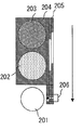
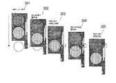
次に、先に述べたNDフィルターについて詳しく述べる。図1のND1(103),ND2(104)は図2に図示したような形状になっている。図2のNDフィルター支持材204によってND1(202)とND2(203)がはめ込まれておりこれが光束201に対して垂直に降りることでNDフィルターが挿入される。NDフィルター支持材204の横にはNDの位置に関連したスリット205が明けられており、図1のND位置状態検出手段111に対応するフォトインターラプタユニット206を遮ることでNDの位置、状態を検出することができる。ただし、実際の装置では鏡筒のスペースの関係上、2枚に分割されている場合もあるが、ここではND位置検出装置を説明するために分かりやすい構成にした。このND位置検出方法は図3に詳しく述べる。301の状態がND1、2とも挿入されておらず、光束を遮るものが何もない状態である。このときフォトインターラプタ206は左端のみONの状態となる。次に302はND1への移行状態であり、このときフォトインターラプタ206は全てOFFの状態となる。次に303はND1が完全に挿入された状態であり、このときフォトインターラプタ303は真中のみONの状態となる。
Next, the ND filter described above will be described in detail. ND1 (103) and ND2 (104) in FIG. 1 have shapes as shown in FIG. ND1 (202) and ND2 (203) are fitted by the ND
次に304はND1からND2への移行状態であり、このときフォトインターラプタ206は左はOFF、真中と右がONの状態となる。次に305はND2が完全に挿入された状態であり、このときフォトインターラプタ206は右のみがONの状態となる。今までのND位置検出結果を2進であらわすと、空、ND1への移行、ND1、ND2への移行、ND2の状態はそれぞれ100、000、010、011,001のようになりそれぞれ独立したパターンで表すことができる。以上説明したような機構を設けることで、NDの入っている状態ばかりでなく、移行期間についても検知することが可能である。
Next,
もちろん、NDの入っていない状態、ND1が挿入されている状態、ND2が挿入されている状態は安定点であり、メカ的にロックされていてもいい。また、移行状態はバネなどの機構でその場所に安定されず、近隣の安定点に移るような機構を設けてあってもよい。 Of course, the state without ND, the state with ND1 inserted, and the state with ND2 inserted are stable points and may be mechanically locked. Further, a mechanism may be provided in which the transition state is not stabilized at the place by a mechanism such as a spring but is shifted to a nearby stable point.
次に前記のNDフィルターが挿入される過程での光量変化がどう変化するかを説明する。 Next, how the light amount change in the process of inserting the ND filter will be described.
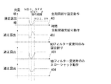
図4はND1からND2への移行するまでの光量変化をあらわした図である。 FIG. 4 is a diagram showing a change in light amount until the transition from ND1 to ND2.
401がND1が入った状態で適正露出になるように絞りを調整された状態から、絞りを固定させた場合の光量の変化を時間ごとに見た図である。ND1がOFFされND2への移行期間中は、図3でも示しているようにND保持材204が大きく光束を遮っている。そのため光量はND1挿入時よりも落ち、またその後のND2が完全に入った状態よりも落ちているのが分かる。また、図2のような絞り機構を使わず、2枚が分割されたものを使っても、同じように光量が落ちるか。もしくは、ND1、ND2を入れたものより光量がふえる場合もある。また、NDなしの状態からNDを入れる場合も本質は同じで、NDを出し入れする際に、ND1、ND2、空の状態、以外の光量変化が存在することになる。
FIG. 401 is a diagram showing a change in light amount over time when the diaphragm is fixed from a state in which the diaphragm is adjusted so as to achieve proper exposure in a state where ND1 is included. During the transition period to ND2 when ND1 is turned off, the
ここでは説明の簡略化のために、ND1からND2への移行期間について考える。 Here, for simplification of description, a transition period from ND1 to ND2 is considered.
今説明したように、401のように絞りを固定させない場合として、本特許を使用しない従来の絞り動作をND切り換え時にも通常動作させた場合を考える。その場合の光量変化を示したのが402になる。402では、始め急激に光量が暗くなるのに対応して絞りを開く方向に動作し、適正露出へ戻りだす動作をする。そのあと、ND保持材が抜けたことにより今度は、明るくなりすぎ、絞りを絞る方向に制御される。結果、暗、明の2回不適切な露出を経由して適正露出に落ち着く動作をする。そこで本発明のNDフィルターが移行期間中は絞りを固定する動作を行った図が403である。403では変化量は通常絞り動作402よりも大きく、多少適正露出になる時間がかかっているが、暗のみにしか行かない露出をとっている。また、本発明のNDフィルターが移行期間中は絞りをスローシャッタ動作を行った図が404である。404では変化量は通常絞り動作402と同等で、暗のみにしか行かない露出をとっている。
As described above, as a case where the diaphragm is not fixed as in 401, a case where a conventional diaphragm operation not using this patent is normally operated even at ND switching will be considered. In this case, 402 shows the change in the amount of light. In 402, in response to the sudden darkening of the amount of light, the aperture is opened in the direction to return to the proper exposure. After that, the ND holding material is removed, and this time, it becomes too bright and is controlled in the direction of narrowing down the aperture. As a result, it operates to settle down to an appropriate exposure through inappropriate exposure twice of dark and light. In view of this,
人間にとって暗明の2回の変化がある映像よりも、1回だけの暗を経るほうが見た目がよくなる効果があり、ND移行期間中の処理を行わない場合よりも見やすい映像になる。 For human beings, there is an effect that the appearance is better when passing only one darkness than an image having two changes of darkness, and the image becomes easier to see than when the processing during the ND transition period is not performed.
今、説明した本発明の制御を図5のフローチャートを用いながら説明する。 Now, the control of the present invention described will be described with reference to the flowchart of FIG.
図5は図4の404の絞り動作を行うためのフローチャートであり、図1のシステムのマイコン114内で動作する。まず、ND位置状態検出装置111からND位置検出動作S501を行う。そして、ND1、ND2の安定状態であるか、移行期間であるか判断する処理S502をおこなう。もし、ND1,ND2が完全に入った状態や両方とも抜けた状態であったら通常処理として現在のND位置情報として現在のND位置を記憶する処理S503を行う。そして、絞り制御モードを光量検出手段に基づく通常絞りモード動作S504で絞り制御を行う。また、先のS502の判断で移行状態であった場合は、先ほどのS503で保存された情報を用いて現在のND1移行期間の場所より、移行期間がどちらからの方向であるかを判別する処理S505を行う。これは、例えば図3の304の絞り状態においてND1⇒ND2と、ND2⇒ND1とでは、条件が異なるのでこれを判別するためである。このようにして、NDフィルターの移行状態とその方向が判断されたところで、その状態と方向ごとにあらかじめ決まった駆動量係数と、間欠駆動量を設定する処理S506を行い。この2つの値を基にS508でスローシャッタモード動作を行う。まず、駆動量係数は、通常動作で1回に絞りが動くべき量を1とすると1以下の係数で、通常動作の動作電圧変化の何割で動かすかを決め反応敏感度量である。また絞りは1秒間に決められた光量検出を行いその回数だけ絞り制御を行う。しかしスローシャッタ動作では、この光検出ができない。もしくはその値を使わず絞り固定絞り制御を間にはさむことで絞りの動きを緩慢にする効果がある。これを間欠駆動動作とよんでいる。このときの何回おきに間欠駆動動作をはさむかを決めるのが間欠駆動量である。これによってスローシャッタ動作を行い絞りの動きを遅くしている。そして、この処理を終えたらまたS501の処理に戻る。ただし、説明したフローを繰り返す時は通常、図1の光量検出手段115が検出結果をもったときであり、撮像素子からの映像信号から出すので1秒間に何回撮像するかによって光量検出手段の出力頻度も変わる。例えば、NTSCのビデオであれば通常はおよそ1秒間に60回、映像を撮るので図5のフローも1秒間に60回行うこととなる。これによって図4の404のようなNDフィルター変更時のみスローシャッタ動作を行うことができる
また、図4の403の絞り固定動作を行うための制御方法を図6を使いながら説明する。ただし、S601、S602,S603,S604は先に説明したS501,S502,S503,S504と同じ動作のため説明を省く。処理S602でND移行期間中と判断された場合、S606で絞りを現在の位置で絞りを固定する処理を行い、絞り固定モード動作で絞りを動作させる。そして、ND移行期間が過ぎた後はS604の通常絞りモード動作で適正露出にされる。これによって図4の403のようなNDフィルター変更時のみ固定絞り動作を行うことができる。
FIG. 5 is a flowchart for performing the
(実施例2)
以下、各図を参照しながら、本発明実施形態2について説明する。
(Example 2)
Hereinafter,
図7は、本発明の実施例である撮影システムの構成を示している。この撮影しシステムは光学手段とその制御手段を含む光学レンズ717と前記光学レンズ717によって導かれた光を撮影する撮影装置718に点線で示されるように物理的に分かれている。この2つの部分が不図の電気的な接点をもって結合することでそれぞれレンズマイコン715とカメラマイコン711が通信しあい、お互いの情報を交換することで全体の撮影動作を可能としている。
FIG. 7 shows the configuration of an imaging system that is an embodiment of the present invention. This photographing system is physically separated as shown by a dotted line in an
まず、光学系に入射した被写体からの光は固定レンズ群701、変倍を行うズームレンズ群(バリエータレンズ)702、を通して入ってきた光が、光量調節を行う為のフィルターとして一番目の濃度の薄いND1(703)と濃度の濃いND2(704)から構成されるNDフィルターを透過する。前記NDフィルター(703,704)により、濃度によって一意的に決まった光量を落とし光量を調節している。そして、前記NDフィルターによって落とされた光がアイリス705に入り、メカ的な機構により光量を可変に調節することが出来、所望の光量に調節される。光量調整された光は、固定されている第三レンズ群706、フォーカシングを行うフォーカスレンズ群(コンペンセータレンズ)707を通り、撮像装置718側に内蔵されたCCD等の撮像素子708上で結像する。撮像素子では光を電気信号に変更されその電気信号が撮像処理手段709によってAGC(オートゲインコントロール)や色調整などを行った後、記録処理手段710に送られ映像信号が録画される。また、撮像処理手段709の映像信号をもとに光量検出装置716では、現在の映像信号が適正な光量なのかを計測し撮像素子に入る光の評価値として検波評価信号作成し。カメラマイコン711が光量検出手段716の検波評価値信号を定期的に検知する。カメラマイコン711は、他のレンズの制御情報と共にレンズマイコン715側に検波評価値を送信する。レンズマイコン715では、カメラマイコン711からのデータを基に絞り制御を行う。絞り705にはメカ的な絞り量を計る絞り位置検出装置713があり、これによって現在の絞りが通す光量変化を電気的に検知することができる。また、この絞り量を電気的に検知することができる。またこの絞り量を変化させるための絞り駆動手段713があり、光量検出手段716で測定された光量に応じて、レンズマイコン715が最適な絞り量になる為の移動量を計算し、絞り駆動手段713に制御電圧をかけることによって絞りの形状を変えて絞り量を変化させる。この動作を繰り返すことにより、最適な光量制御をおこなっている。
First, light from a subject incident on the optical system is incident on the fixed
また、NDフィルターの詳細な説明や、ND移行時の光量変化については、実施例1と同じであるので説明を省く。 The detailed description of the ND filter and the change in the amount of light at the ND shift are the same as those in the first embodiment, and thus the description thereof is omitted.
実施例2の絞り制御を図5のフローチャートを用いながら説明する。 The aperture control according to the second embodiment will be described with reference to the flowchart of FIG.
図8は図4の404の絞り動作を行うためのフローチャートであり、図7のシステムのレンズマイコン715内で動作する。まず、ND位置状態検出装置712からND位置検出S801を行う。そして、ND1、ND2の安定状態であるか、移行期間であるか判断する処理S802をおこなう。もし、ND1,ND2が完全に入った状態であったら通常処理として現在のND位置情報として現在のND位置を記憶する処理S803を行う。そして、絞り制御モードを光量検出手段に基づく通常絞りモード動作S804で絞り制御を行う。また、先のS802の判断で移行状態であった場合は、先ほどのS803で保存された情報を用いて現在のND1移行期間の場所より、移行期間がどちらからの方向であるかを判別するS805を行う。これは、例えば図3の304の絞り状態においてND1⇒ND2と、ND2⇒ND1とでは、条件が異なるのでこれを判別するためである。このようにして、NDフィルターの移行状態とその方向が判断されたところで、その状態と方向ごとにあらかじめ決まった駆動量係数と、間欠駆動量を設定する処理S806を行い。この2つの値を基にS808でスローシャッタモード動作を行う。まず、駆動量係数は、通常動作で1回に絞りが動くべき量を1とすると1以下の係数で、通常動作の動作電圧変化の何割で動かすかを決定する反応敏感度量である。また絞りは1秒間に決められた光量検出を行いその回数だけ絞り制御を行う。しかしスローシャッタ動作では、この光検出ができない。もしくはその値を使わず絞り固定絞り制御を間にはさむことで絞りの動きを緩慢にする効果がある。これを間欠駆動動作と呼んでいる。このときの何回おきに間欠駆動動作をはさむかを決めるのが間欠駆動量である。これによってスローシャッタ動作を行い絞りの動きを遅くしている。そして、S807かS804の絞り動作を終了したら、レンズマイコンからカメラマイコン側に先の処理S801及びS805で分かったNDの状態をカメラマイコン側に送信する処理S808を行う。これによってカメラマイコン側では、光量検出の回数を減らしたりAGCの特性を変えることもできるし、画像処理によって撮影された映像を加工することもできる。そして、またS801の処理に戻る。ただし、説明したフローを繰り返す時は通常、図1の光量検出手段115が検出結果をもったときであり、撮像素子からの映像信号から出すので1秒間に何回撮像するかによって光量検出手段の出力頻度も変わる。例えば、NTSCのビデオであれば通常はおよそ1秒間に60回、映像を撮るので図5のフローも1秒間に60回行うこととなる。
FIG. 8 is a flowchart for performing the
Claims (4)
前記ND位置状態検出手段は、前記NDフィルターが挿入状態であるか、前記NDフィルターが離脱状態であるか、または、前記NDフィルターが前記挿入状態と前記離脱状態の間の移行期間中であるかを検知する機能を備えており、
前記NDフィルターが前記移行期間の場合、前記絞りの絞り制御を固定することを特徴とする光学装置。 A diaphragm for adjusting the amount of light flux from the subject incident on the optical system facing the image sensor, and an optical axis of the optical system for adjusting the amount of light flux from the subject incident on the optical system toward the image sensor An optical device having an ND filter inserted and removed, and an ND position state detection means for detecting the state of the ND filter ,
Whether the ND position state detection means is the ND filter being inserted, whether the ND filter is in a detached state, or whether the ND filter is in a transition period between the inserted state and the detached state It has a function to detect
An optical apparatus characterized in that the diaphragm control of the diaphragm is fixed when the ND filter is in the transition period.
前記ND位置状態検出手段は、前記NDフィルターが挿入状態であるか、前記NDフィルターが離脱状態であるか、または、前記NDフィルターが前記挿入状態と前記離脱状態の間の移行期間中であるかを検知する機能を備えており、
前記NDフィルターが前記移行期間の場合、前記絞りの絞り制御をスローシャッタ動作とすることを特徴とする光学装置。 A diaphragm for adjusting the amount of light flux from the subject incident on the optical system facing the image sensor, and an optical axis of the optical system for adjusting the amount of light flux from the subject incident on the optical system toward the image sensor An optical device having an ND filter inserted and removed, and an ND position state detection means for detecting the state of the ND filter ,
Whether the ND position state detection means is the ND filter being inserted, whether the ND filter is in a detached state, or whether the ND filter is in a transition period between the inserted state and the detached state It has a function to detect
When the ND filter is in the transition period, the aperture control of the aperture is a slow shutter operation.
Priority Applications (1)
| Application Number | Priority Date | Filing Date | Title |
|---|---|---|---|
| JP2004211456A JP4455200B2 (en) | 2004-07-20 | 2004-07-20 | Aperture control |
Applications Claiming Priority (1)
| Application Number | Priority Date | Filing Date | Title |
|---|---|---|---|
| JP2004211456A JP4455200B2 (en) | 2004-07-20 | 2004-07-20 | Aperture control |
Publications (3)
| Publication Number | Publication Date |
|---|---|
| JP2006030769A JP2006030769A (en) | 2006-02-02 |
| JP2006030769A5 JP2006030769A5 (en) | 2007-09-06 |
| JP4455200B2 true JP4455200B2 (en) | 2010-04-21 |
Family
ID=35897166
Family Applications (1)
| Application Number | Title | Priority Date | Filing Date |
|---|---|---|---|
| JP2004211456A Expired - Fee Related JP4455200B2 (en) | 2004-07-20 | 2004-07-20 | Aperture control |
Country Status (1)
| Country | Link |
|---|---|
| JP (1) | JP4455200B2 (en) |
Families Citing this family (1)
| Publication number | Priority date | Publication date | Assignee | Title |
|---|---|---|---|---|
| JP5911261B2 (en) * | 2011-10-26 | 2016-04-27 | キヤノン株式会社 | Imaging device |
-
2004
- 2004-07-20 JP JP2004211456A patent/JP4455200B2/en not_active Expired - Fee Related
Also Published As
| Publication number | Publication date |
|---|---|
| JP2006030769A (en) | 2006-02-02 |
Similar Documents
| Publication | Publication Date | Title |
|---|---|---|
| JP3950707B2 (en) | Optical equipment | |
| US10244170B2 (en) | Image-shake correction apparatus and control method thereof | |
| US7830422B2 (en) | Lens apparatus, image-pickup apparatus, and image-pickup system | |
| JP6749791B2 (en) | Imaging device and automatic focusing method | |
| JP2009115921A (en) | Imaging apparatus | |
| JP6560030B2 (en) | Lens unit and aperture control method | |
| JP5366643B2 (en) | Imaging device | |
| US7046279B2 (en) | Image taking apparatus | |
| JP2008211630A (en) | Imaging apparatus | |
| JP2007199195A (en) | Lens controller | |
| JP6202953B2 (en) | Optical equipment | |
| JP2006330567A (en) | Autofocus device | |
| JP4941141B2 (en) | Imaging device | |
| JP2023159227A (en) | Imaging apparatus | |
| JP4455200B2 (en) | Aperture control | |
| JP2008203428A (en) | Imaging apparatus | |
| JP2011118021A (en) | Imaging device and method for controlling the same | |
| JP2008158028A (en) | Electronic still camera | |
| JP2007025432A (en) | Exposure control method of imaging apparatus | |
| JP4961334B2 (en) | Imaging apparatus and control method thereof | |
| JP4066244B2 (en) | Auto focus system | |
| JP5438496B2 (en) | Imaging apparatus, control method therefor, and program | |
| JP4933195B2 (en) | Lens control device and imaging device | |
| JP2008298956A (en) | Imaging apparatus | |
| JP2009109792A (en) | Autofocusing device and camera using it |
Legal Events
| Date | Code | Title | Description |
|---|---|---|---|
| A521 | Request for written amendment filed |
Free format text: JAPANESE INTERMEDIATE CODE: A523 Effective date: 20070719 |
|
| A621 | Written request for application examination |
Free format text: JAPANESE INTERMEDIATE CODE: A621 Effective date: 20070719 |
|
| A977 | Report on retrieval |
Free format text: JAPANESE INTERMEDIATE CODE: A971007 Effective date: 20090924 |
|
| A131 | Notification of reasons for refusal |
Free format text: JAPANESE INTERMEDIATE CODE: A131 Effective date: 20091006 |
|
| A521 | Request for written amendment filed |
Free format text: JAPANESE INTERMEDIATE CODE: A523 Effective date: 20091203 |
|
| TRDD | Decision of grant or rejection written | ||
| RD04 | Notification of resignation of power of attorney |
Free format text: JAPANESE INTERMEDIATE CODE: A7424 Effective date: 20100201 |
|
| A01 | Written decision to grant a patent or to grant a registration (utility model) |
Free format text: JAPANESE INTERMEDIATE CODE: A01 Effective date: 20100202 |
|
| A01 | Written decision to grant a patent or to grant a registration (utility model) |
Free format text: JAPANESE INTERMEDIATE CODE: A01 |
|
| A61 | First payment of annual fees (during grant procedure) |
Free format text: JAPANESE INTERMEDIATE CODE: A61 Effective date: 20100203 |
|
| FPAY | Renewal fee payment (event date is renewal date of database) |
Free format text: PAYMENT UNTIL: 20130212 Year of fee payment: 3 |
|
| R150 | Certificate of patent or registration of utility model |
Ref document number: 4455200 Country of ref document: JP Free format text: JAPANESE INTERMEDIATE CODE: R150 Free format text: JAPANESE INTERMEDIATE CODE: R150 |
|
| FPAY | Renewal fee payment (event date is renewal date of database) |
Free format text: PAYMENT UNTIL: 20140212 Year of fee payment: 4 |
|
| LAPS | Cancellation because of no payment of annual fees |