JP4454501B2 - Draft roller cover - Google Patents
Draft roller cover Download PDFInfo
- Publication number
- JP4454501B2 JP4454501B2 JP2004561323A JP2004561323A JP4454501B2 JP 4454501 B2 JP4454501 B2 JP 4454501B2 JP 2004561323 A JP2004561323 A JP 2004561323A JP 2004561323 A JP2004561323 A JP 2004561323A JP 4454501 B2 JP4454501 B2 JP 4454501B2
- Authority
- JP
- Japan
- Prior art keywords
- layer
- belt
- outer layer
- fiber
- running
- Prior art date
- Legal status (The legal status is an assumption and is not a legal conclusion. Google has not performed a legal analysis and makes no representation as to the accuracy of the status listed.)
- Expired - Fee Related
Links
Images


Classifications
-
- D—TEXTILES; PAPER
- D01—NATURAL OR MAN-MADE THREADS OR FIBRES; SPINNING
- D01H—SPINNING OR TWISTING
- D01H5/00—Drafting machines or arrangements ; Threading of roving into drafting machine
- D01H5/18—Drafting machines or arrangements without fallers or like pinned bars
- D01H5/70—Constructional features of drafting elements
- D01H5/74—Rollers or roller bearings
- D01H5/80—Rollers or roller bearings with covers; Cots or covers
Abstract
Description
本発明は、装備されている加圧ロール用のカバーが外層と内層から構成されておりかつ外層が内層より薄い層厚を有している紡糸機用ローラドラフト装置、および、このような紡糸機用ドラフト装置の加圧ローラに用いられる層厚の薄い外層が層厚の厚い内層に対して移動可能なように外層が内層を緩く囲んでいるカバーとして使用するためのベルトまたは外被に関する。 The present invention relates to a roller draft device for a spinning machine, in which the cover for the pressure roll provided is composed of an outer layer and an inner layer, and the outer layer has a thinner layer thickness than the inner layer, and such a spinning machine. The present invention relates to a belt or jacket for use as a cover in which an outer layer loosely surrounds an inner layer so that the outer layer having a small layer thickness used for a pressure roller of a draft device can move relative to the thick inner layer.
ドラフト装置においてファイバー束をドラフトする場合、ローラ対のクランプ性能がドラフト力のファイバー束への移動における重要な作用を果たす。そのため、ドラフト装置のローラ対は、下部シリンダーといわれる溝付の鋼のシリンダーと、上部ローラといわれる加圧ローラとから構成されており、加圧ローラが所定の負荷によって鋼のシリンダー上に押しつけられている。原則として、この加圧ローラは弾性体のカバーを含んでおり、この弾性カバーのためクランプ線がファイバー上に認められることがなく、またこの弾性カバーの変形によってクランプ面が形成され、この面によりファイバーが極めて良好に把持される。すなわち、ファイバーを損傷することなく、良好なクランプ作用がファイバー構造体上に働く。カバーが柔軟であるほどクランプ面が広くなるため、経験上、柔軟なローラカバーが良好なドラフト結果をもたらすことがわかっている。しかしながら、柔軟なローラカバーは極めて急速に磨耗し、特にファイバーが通過する領域に溝が形成されてしまうという問題を有している。このいわゆる“目減り”は、カバーの表面全体を研削することによって回避できる。しかしながらこの研削によりドラフト装置のローラの形状が変化し、それとともにカバーの性質も変化する。カバーの特性が変化すると、ドラフト条件に対して、従って紡績糸の特性値に対しても、悪影響が現われる。さらに、ローラカバーの再研削の費用は極めて高額である。 When drafting a fiber bundle in a draft device, the clamping performance of the roller pair plays an important role in the movement of the draft force to the fiber bundle. Therefore, the roller pair of the draft device is composed of a grooved steel cylinder called a lower cylinder and a pressure roller called an upper roller, and the pressure roller is pressed onto the steel cylinder by a predetermined load. ing. As a general rule, this pressure roller includes an elastic cover, so that the clamp line is not recognized on the fiber because of this elastic cover, and the clamp surface is formed by deformation of this elastic cover. The fiber is very well gripped. That is, a good clamping action works on the fiber structure without damaging the fiber. Experience has shown that a flexible roller cover provides good draft results because the softer the cover, the wider the clamping surface. However, the flexible roller cover wears very rapidly, and has the problem that grooves are formed, especially in the area where the fiber passes. This so-called “loss” can be avoided by grinding the entire surface of the cover. However, this grinding changes the shape of the draft roller, and the properties of the cover change accordingly. Any change in the cover properties will have an adverse effect on the draft conditions and thus on the spun yarn properties. Furthermore, the cost of regrinding the roller cover is very high.
従って、複数層のローラカバーによりこの問題点に対抗する試みがなされてきた。DE1815739U号公報は、ローラの弾性ジャケットが少なくとも2層に細分化されている加圧ローラを開示しており、これらの層のうちの外層が薄いホースから構成される弾性体の外被として設計されており、加圧ローラの弾性ジャケット上にこのホースを引っ張って被せることができる。外層をホースとして設計すると、弾性ジャケットの上にカバーを引っ張って被せやすく、この外層の外周面が磨耗した場合には、容易に弾性ジャケットから取り外すことができる。この弾性ホースは、ゴムとゴムとの間の固有の摩擦によって固定されている。この公知の設計により、弾性を示す外層を容易に交換することができるものの、急速な磨耗と目減りの問題は解決されなかった。 Accordingly, attempts have been made to counter this problem with multiple layers of roller covers. DE1815739U discloses a pressure roller in which the elastic jacket of the roller is subdivided into at least two layers, and the outer layer of these layers is designed as an outer envelope of a thin hose. The hose can be pulled over the elastic jacket of the pressure roller. When the outer layer is designed as a hose, it is easy to cover the elastic jacket by pulling the cover, and when the outer peripheral surface of the outer layer is worn, it can be easily removed from the elastic jacket. This elastic hose is fixed by the inherent friction between rubber. Although this known design allows the elastic outer layer to be easily replaced, the problem of rapid wear and loss of wear has not been solved.
DE1685634A1号公報は、紡糸機のドラフト装置のローラに用いられる2層の積層された円筒状の層で構成されたカバーを開示しており、このカバーの外層は内層より硬くかつ層厚が薄い。この2層は互いに接着されている。その結果、屈曲部の形成および静電気の発生を回避するために、全く異なる材料を互いに組み合わせることができる。しかしながら、この形態では良好なドラフト能力および磨耗性の問題を満足のいく程度に解決できないことがわかった。その上、接着の結果として、外層の交換の費用が高額である。 DE 1685634A1 discloses a cover composed of two laminated cylindrical layers used for the rollers of a drafting device of a spinning machine, the outer layer of this cover being harder and thinner than the inner layer. The two layers are bonded together. As a result, completely different materials can be combined with each other to avoid the formation of bends and the generation of static electricity. However, it has been found that this form does not satisfactorily solve the problems of good drafting and wear. Moreover, as a result of bonding, the cost of replacing the outer layer is high.
本発明の課題は、上述の問題点を回避し、走行層の磨耗耐久性が高くかつ弾性が長持ちするローラカバーであって、従って長期間最適なドラフト条件を確保できるローラカバーを提供することである。 An object of the present invention is to provide a roller cover that avoids the above-mentioned problems, has a high wear durability of the running layer and has a long-lasting elasticity, and can therefore ensure optimum draft conditions for a long period of time. is there.
上述の課題は、請求項1に示す、装備されている加圧ロール用のカバーが外層と内層から構成されており、外層が内層より薄い層厚を有している、紡糸機用のローラドラフト装置であって、カバーの外層が内層に対して移動することができるように外層が内層を緩く囲んでいることを特徴とする装置によって解決される。意外にも、薄い外層と厚い内層を備えた複数層のカバーにおいて、2層が相対的に移動することができる点が重要であることがわかった。従って、柔軟なカバーの圧延運動とそれによって引き起こされる張力が薄い外層の内面にのみ移動し、ファイバーおよび溝付のシリンダーには移動しない。磨耗が事実上もはや起こらず、特に溝が形成されない(目減りが起こらない)ため、外層の寿命が3倍以上に延長される。 The above-mentioned problem is a roller draft for a spinning machine according to claim 1, wherein the cover for the pressure roll provided is composed of an outer layer and an inner layer, and the outer layer has a thinner layer thickness than the inner layer. The device is solved by a device characterized in that the outer layer loosely surrounds the inner layer so that the outer layer of the cover can move relative to the inner layer. Surprisingly, it has been found that in a multi-layer cover with a thin outer layer and a thick inner layer, the two layers can move relatively. Therefore, the rolling movement of the flexible cover and the tension caused thereby moves only to the inner surface of the thin outer layer and not to the fiber and grooved cylinder. The wear of the outer layer is practically no longer occurring and in particular no grooves are formed (no loss of sight), so that the life of the outer layer is extended by more than three times.
好適には、外層の外面は、ファイバー接触層として、良好なファイバークランプの要請に適合させ、内面は、走行層として、できるだけ円滑に加圧ローラの低摩擦での走行が起こるようにする。この点は、例えば外層におけるファイバー接触層と走行層用の材料組成を適当に選択するという簡単な方法によって達成される。この外層は、加圧ローラの内層の外被として、またはエンドレスベルトとして設計できる。尤も、外層は柔軟な内層の変形に順応するように柔軟でなければならない。外層をファイバー構造体の移動方向、すなわち、ローラの軸に垂直な方向に対してできるだけ非弾性的に設計するのが、すなわちできるだけ低い伸びを示すように設計するのが極めて好ましいことがわかっている。磨耗を引き起こしかつドラフト性に悪影響を及ぼすクランプ面の張力はこの方法により除去される。一方、外層は、ローラの軸の方向においては、ファイバー構造体によるしわに順応しうる。このようにして優れたクランプ性が達成される。加圧ローラの軸に垂直な方向への外層の伸びの望ましい低減は、紡績糸のインサートによって、ローラの軸の方向への伸びをなんら制限することなく極めて良好に達成される。外層と内層の間の相対的な移動は、外層の走行層面をできるだけ平滑にすることによって好ましく達成され、その結果、張力が一層良好な方法で抑えられる。 Preferably, the outer surface of the outer layer is adapted as a fiber contact layer to meet the requirements of good fiber clamps and the inner surface is adapted as a running layer so that the pressure roller runs as smoothly as possible with low friction. This is achieved, for example, by a simple method of appropriately selecting the material composition for the fiber contact layer and the running layer in the outer layer. This outer layer can be designed as an outer covering of the inner layer of the pressure roller or as an endless belt. However, the outer layer must be flexible to accommodate the deformation of the flexible inner layer. It has been found that it is highly preferable to design the outer layer as inelastic as possible with respect to the direction of movement of the fiber structure, i.e. perpendicular to the axis of the roller, i.e. exhibiting the lowest possible elongation. . Clamping surface tensions that cause wear and adversely affect drafting are removed by this method. On the other hand, the outer layer can adapt to wrinkles due to the fiber structure in the direction of the axis of the roller. In this way, excellent clamping properties are achieved. The desired reduction in the elongation of the outer layer in the direction perpendicular to the axis of the pressure roller is achieved very well by the spun yarn insert without any restriction in the direction of the axis of the roller. The relative movement between the outer layer and the inner layer is preferably achieved by making the running layer surface of the outer layer as smooth as possible, so that the tension is suppressed in a better way.
高速のファイバー排出速度の場合には、ベルトとして設計された外層を使用し、偏向レールを用いてこのベルトを走行させるのが好ましい。さらに、この偏向レールは、さらに信頼性が高い案内を確保するために、側方リムを有することもできる。また、高速のファイバー排出速度では、問題のないファイバー移動を確保するために、ベルトがファイバー構造体の面に対して30°より大きな角度で加圧ローラから離れるようにするのが特に好ましいことがわかっている。ベルトは複数層から構成されているのが好ましく、内側が平滑な走行層として、外側がファイバー接触層として設計されているのが好ましい。2層の間に紡績糸のインサートを設け、このインサートにより、ベルトの移動方向と垂直な方向における望ましいベルトの伸びにはなんら悪影響を及ぼさないようにしながら、ベルトの移動方向への伸びを回避することができる。 For high fiber ejection speeds, it is preferred to use an outer layer designed as a belt and run this belt using a deflection rail. Furthermore, the deflection rail can also have side rims in order to ensure a more reliable guide. Also, at high fiber ejection speeds, it is particularly preferred that the belt be separated from the pressure roller at an angle greater than 30 ° with respect to the surface of the fiber structure in order to ensure trouble-free fiber movement. know. The belt is preferably composed of a plurality of layers, preferably designed as a smooth running layer on the inside and a fiber contact layer on the outside. An insert of spun yarn is provided between the two layers, and this insert avoids any adverse effect on the desired belt stretch in the direction perpendicular to the belt travel direction, while avoiding stretch in the belt travel direction. be able to.
以下、本発明を図面を使用して詳細に説明する。 Hereinafter, the present invention will be described in detail with reference to the drawings.
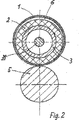
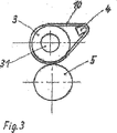
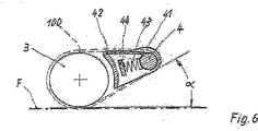
図1は、本発明のドラフト装置の2層のローラカバーの縦断面図であり、図2は、図1に示す装置の断面図である。図3は、ベルトとして設計された外層を示す図である。図4、5は、ローラの軸に垂直な方向に補強するためのインサートを備えた外層の設計を概略的に示す図である。図6は、偏向レールによるベルトの案内を示す断面図であり、図7は図6の平面図である。 FIG. 1 is a longitudinal sectional view of a two-layer roller cover of the draft device of the present invention, and FIG. 2 is a sectional view of the device shown in FIG. FIG. 3 is a diagram showing an outer layer designed as a belt. 4 and 5 schematically show the design of the outer layer with an insert for reinforcement in a direction perpendicular to the axis of the roller. 6 is a cross-sectional view showing guide of the belt by the deflection rail, and FIG. 7 is a plan view of FIG.
図1、2において、加圧ローラ3は、ドラフト装置のシリンダー5上に配置されており、加圧ローラ3に慣用的な方法で常に接続されているカバー2を備えている。ドラフト装置のシリンダー5と加圧ローラ3とは、高速で走行するとともにファイバーを排出する作用を果たすドラフト装置の出口のローラ対を形成する。内層としての加圧ローラ3の被覆2の上には、外層としての別の被覆1が備えられている。この外層は、図示した形態では、薄層の外被1から構成されており、この外被1は、外被1の移動方向に対しては内層2の材料に比較して事実上伸びないで移動する柔軟な材料で構成されている。この外被1は加圧ローラ3の内層2上を緩く滑るため、内層と外層の間の無負荷の領域には空間6が形成されうる。外被1が加圧ローラ3の内層2に対して移動することができるということは、本質的な点である。一方、内層2は、通常どおり加圧ローラ3上に引っ張られて堅固に被せられている。加圧ローラ3の負荷により、柔軟な内層2がドラフト装置のシリンダー5上に押し付けられ、変形する。従って、ドラフト装置のシリンダー5との間に直線的な接触が起こらず、むしろ平面的な支持が発生する。外層1は薄くかつ柔軟であるため、実質上それ自身が圧縮されずに内層2の変形に順応する。従って、内層と対比すると、外層の場合には明らかな加圧作用を示さない。内層2の変形によってもたらされるクランプ面は外層1によって伝達され、ドラフトに供されたファイバー構造体Fがローラ対3、5間を通過する際にこのクランプ面によってクランプされる。
1 and 2, the pressure roller 3 is arranged on a
従来の加圧ローラのカバーの場合は、クランプ面は柔軟な弾性カバーで形成され、この弾性カバーの表面が良好なクランプ作用を果たしている。しかしながら、カバーの加圧作用によってクランプ面の領域に張力が発生し、この張力がドラフトの間にファイバー構造体に悪影響を及ぼすと共に公知のようにカバーの深刻な磨耗を引き起こす。しかしながら、加圧ローラ3の柔軟な弾性カバー2の変形に柔軟に順応するもののその薄い層厚と変形性のために加圧作用を全く示さないかまたは極めてわずかにしか示さない本発明の外層1の配置により、意外にも、外層1が極めて大きな安定性を示すとともに、柔軟な内層2が通常認められる磨耗および目減りの現象を示さないという結果が得られる。広範な試験において、外層1は従来のカバーの耐用時間の3倍に至っても依然として何ら問題なく走行し、交換する必要がないことがわかった。ドラフト値も、従来の新しいカバーに比較して改善可能でさえあった。この意外な結果は、加圧ローラ3の柔軟で弾性を示す内層2の加圧作用によって引き起こされる張力がクランプされたファイバー構造体に影響し得ないという事実のためであると考えられる。これらの張力は柔軟な内層2と外層1の平坦な走行層102との間で生じうる相対的な移動によって低減される。ファイバーとドラフト装置のシリンダー5の間には、またファイバーと外層1との間には、相対的な移動が生じないため、静止摩擦の領域でクランプが行われる。従って、滑りによって引き起こされる磨耗が生じ得ない。
In the case of a conventional pressure roller cover, the clamp surface is formed of a flexible elastic cover, and the surface of this elastic cover performs a good clamping action. However, the pressure action of the cover creates tension in the area of the clamping surface, which adversely affects the fiber structure during the draft and causes serious wear of the cover as is known. However, the outer layer 1 of the present invention which adapts flexibly to the deformation of the flexible elastic cover 2 of the pressure roller 3 but exhibits no or very little pressing action due to its thin layer thickness and deformability. Surprisingly, the result is that the outer layer 1 exhibits very great stability and the flexible inner layer 2 does not exhibit the normally observed wear and loss of wear phenomenon. In a wide range of tests, it was found that the outer layer 1 still runs without any problems and does not need to be replaced even when it reaches three times the useful life of a conventional cover. The draft value could even be improved compared to the conventional new cover. This surprising result is believed to be due to the fact that the tension caused by the pressure action of the soft and elastic inner layer 2 of the pressure roller 3 cannot affect the clamped fiber structure. These tensions are reduced by the relative movement that can occur between the flexible inner layer 2 and the flat running layer 102 of the outer layer 1. Since there is no relative movement between the fiber and the
図1、2に示した実施形態では、外層1が円筒状の外被1として設計されている。しかしながら、外層1はかなり長いエンドレスベルトとして設計することもできる。この円筒状の外被1およびベルト10または100は、磨耗した場合に、またはファイバー構造体Fが通過する領域に溝が形成された場合に、容易に交換することができる。図3は、柔軟な弾性体の内層2を備えた加圧ローラ3を囲んでおりかつ偏向レール4に案内されているエンドレスベルト10を示している。かなり長いエンドレスベルト10または100としての構成および偏向レール4による案内は、装置が高速のファイバー排出速度で操作されている場合に、特に好適であることがわかっている。
In the embodiment shown in FIGS. 1 and 2, the outer layer 1 is designed as a cylindrical jacket 1. However, the outer layer 1 can also be designed as a fairly long endless belt. The cylindrical jacket 1 and the
特別なドラフトの場合には、ファイバー排出ローラ対を形成するドラフト装置3、5が主ドラフト域の前に配置されておりかつ通常はファイバー案内ベルトにより囲まれているローラ対に比較して約20〜30倍速く走行することを考慮に入れなければならない。これらの公知のファイバー案内ベルトは、出口のロール対3、5の外層1として使用するのに適していないことがわかった。これらのベルトは特性において不十分である。例えば、外層1またはベルト10または100がファイバー構造体Fの移動方向、すなわちローラ軸31に対して垂直な方向、に対してできるだけ非弾性的であり、そのため伸びることができない点が重要であることがわかった。
In the case of a special draft, a
もちろん、物理的な意味で伸びを完全に排除することはできないが、できるだけ少ないのが望ましい。このことは、紡績糸のインサート103によって簡単に達成される。その上、公知のベルトの場合はドラフトの間にファイバーが滑りやすいが、この滑りは出口のローラ対にとっては望ましくない。
Of course, the elongation cannot be completely eliminated in a physical sense, but it is desirable that it be as small as possible. This is easily achieved by the spun
図4は、外層1、10または100の設計の断面図を示しているが、この図により望ましい性質がさらに理解される。外被1または長く伸びたエンドレスベルト10または100として設計された外層1は、複数の層、すなわち、ファイバー接触層101と走行層102から構成されるのが好ましい。紡績糸のインサート103は両層101、102の間に縦方向の伸びを回避するために配置されており、この紡績糸のインサートはファイバー接触層101および走行層102の両方に堅固に接続されている。ファイバー接触層101は、ファイバー構造体Fと接触する面およびその材料において、ドラフトの間の把持力の要請に応ずることができるように設計される。この点は、ファイバー接触層101に対して例えば加圧ローラのカバーに使用されている材料と同様の材料を使用することにより達成される。他方、走行層102は、内層2の周囲を外層1、10、100が相対的に移動可能なように、滑りやすい平滑な面を備えている。主ドラフト域における通常のファイバー案内ベルトのための材料のような滑りやすい材料が、走行層102に対して好ましく使用される。
FIG. 4 shows a cross-sectional view of the design of the
紡績糸のインサート103がベルト100から移動方向に対する弾性を失わせるため、伸びが事実上起こらない。しかしながら、移動方向に垂直な方向、すなわち、加圧ローラの軸31の方向、に対する伸びは残っている。ベルトはドラフトされたファイバー構造体Fによるしわに順応することができるため、良好なクランプが常に達成される。外層がこのように複数層から構成されていても、外層は、ファイバー構造体Fおよび内層2の変形に順応するための良好な柔軟性を示すように、当然厚すぎてはならない。安定性およびドラフト結果を考慮すると、全体の厚みが0.8〜1.0mmであるのが特に好ましいことがわかっている。走行時間が数年に及んでもなお、溝の形成(目減りの発生)は認められなかった。
Since the spun
走行層102とファイバー接触層101における望ましい特性は、表面の適当な物理的形状によっても達成することができる。しかしながら、走行層102およびファイバー接触層101は、所望のすべり特性および要求される把持力を有する別々の材料で構成されるのが好ましい。DIN53375に従って測定すると、例えばファイバー接触層101用の上述の材料は、走行層102を主ドラフト域におけるファイバー案内ベルトに使用されるのと同様の材料で構成した場合に、走行層102の摩擦力の少なくとも2倍の高い摩擦力を有することがわかった。従って、走行層102は良好な滑り特性を示し、一方ファイバー接触層101は優れたファイバークランプ性能を達成する。 Desirable properties in the running layer 102 and the fiber contact layer 101 can also be achieved by an appropriate physical shape of the surface. However, the running layer 102 and the fiber contact layer 101 are preferably composed of separate materials having the desired slip characteristics and the required gripping force. When measured in accordance with DIN 53375, for example, the above-mentioned materials for the fiber contact layer 101 can be used for the frictional force of the traveling layer 102 when the traveling layer 102 is composed of the same material used for the fiber guide belt in the main draft region. It was found to have at least twice as much friction. Thus, the running layer 102 exhibits good sliding properties, while the fiber contact layer 101 achieves excellent fiber clamping performance.
図4、5に示すようなエンドレスベルトの製造は、例えば、ベルトの長さに対応する円周を有する管状体上に第1の内部層として走行層102を設け、その上に紡績糸のインサート103を形成する紡績糸を巻きつける。次いで、この紡績糸のインサート103をファイバー接触層101で覆う。
4 and 5, for example, an endless belt is manufactured by providing a traveling layer 102 as a first inner layer on a tubular body having a circumference corresponding to the length of the belt, and inserting a spun yarn thereon. The spun yarn forming 103 is wound. The spun
図6、7に示す形態では、ベルト100が変更レール4を通過して走行している。ベルト100を円滑に走行させることができるように、変更レール4を丸くするだけでなくさらに低摩擦の被覆を施す。案内リム41を備えたケージ42がこの変更レール4に付属されている。変更レール4とドラフト装置のローラ3との間の空間は、このケージ42とその案内リム41によって囲まれているため、この空間に綿毛が集積するのが回避される。ベルト100は、ファイバー構造体Fの面に対して所定の角度αで、ドラフト装置のローラ3から離れて走行する。このことにより、ファイバー構造体Fが出口領域で乱れて流れたり飛び回ったりするのが回避される。ケージ42は圧力スプリング43を介した保持レール44に支持されているため、変更レール4がベルト100に張力を及ぼす。側方リム41は、ベルト100の側面を案内する役割を果たす。この形態でも容易かつ迅速にベルト100を交換することができる。変更レール4を押し戻すことによってベルト100の緊張を解き、側方リム41上にベルト100を容易に持ち上げることができる。これらの側方リム41はまた、加圧ローラ3と変更レール4の間の空間を包囲するだけでなく、ベルト100の側面を案内する役割も果たす。加圧ローラ3の外層1がファイバー構造体Fに対して非対称的に配置されている場合には、ベルト100の再設置に当たって、外層1をその左側が右側に来るように向きを変えて配置することにより、ファイバー構造体Fが外層の未使用面上を走行するようにすることができる。
In the form shown in FIGS. 6 and 7, the
1 外層
2 内層
3 加圧ローラ
4 偏向レール
5 シリンダー
10、100 エンドレスベルト
DESCRIPTION OF SYMBOLS 1 Outer layer 2 Inner layer 3 Pressure roller 4
Claims (34)
外層(1、10、100)が内層(2)に対して移動することができるように、外層(1、10、100)が内層(2)を緩く囲んでいることを特徴とする装置。Pressure low La that has been installed on the outlet of the draft zone (3) cover formed of a flexible material for (1,10,100,2) is an outer layer (1, 10, 100), the pressure roller (3) solid and constant has been that the inner layer (2) to have been composed of the outer layer (1, 10, 100) has a and thin layer thickness harder than the inner layer (2), for the spinning machine A roller draft device,
Device characterized in that the outer layer (1, 10, 100) loosely surrounds the inner layer (2) so that the outer layer (1, 10, 100) can move relative to the inner layer (2).
加圧ロール(3)の内層(2)に対向する走行層(102)と、
ファイバー構造体(F)に対向するファイバー接触層(101)を含むことを特徴とする請求項19に記載の装置。 The outer layer (1, 10, 100)
A traveling layer (102) facing the inner layer (2) of the pressure roll (3);
20. The device according to claim 19, comprising a fiber contact layer (101) facing the fiber structure (F) .
エンドレスベルト(1、10、100)が、その移動方向を横切る方向よりも該移動方向に低い伸びを示すように設計されていることを特徴とするエンドレスベルト。It is composed of an outer layer and an inner layer used for a pressure roller of a draft device for a spinning machine. An endless belt for use as a cover loosely surrounding the inner layer (2) so that can move relative to the inner layer (2),
Endless belt, characterized in that the endless belt (1, 10, 100) is designed to exhibit a lower extension in the direction of movement than in the direction across it.
Applications Claiming Priority (2)
| Application Number | Priority Date | Filing Date | Title |
|---|---|---|---|
| DE10260025A DE10260025A1 (en) | 2002-12-19 | 2002-12-19 | Coating for drafting rollers |
| PCT/EP2003/014369 WO2004057072A1 (en) | 2002-12-19 | 2003-12-17 | Covering for drafting rollers |
Publications (2)
| Publication Number | Publication Date |
|---|---|
| JP2006510816A JP2006510816A (en) | 2006-03-30 |
| JP4454501B2 true JP4454501B2 (en) | 2010-04-21 |
Family
ID=32477874
Family Applications (1)
| Application Number | Title | Priority Date | Filing Date |
|---|---|---|---|
| JP2004561323A Expired - Fee Related JP4454501B2 (en) | 2002-12-19 | 2003-12-17 | Draft roller cover |
Country Status (9)
| Country | Link |
|---|---|
| US (1) | US7140172B2 (en) |
| EP (1) | EP1576217B1 (en) |
| JP (1) | JP4454501B2 (en) |
| CN (1) | CN1729323B (en) |
| AT (1) | ATE458075T1 (en) |
| AU (1) | AU2003294876A1 (en) |
| DE (2) | DE10260025A1 (en) |
| ES (1) | ES2338546T3 (en) |
| WO (1) | WO2004057072A1 (en) |
Families Citing this family (8)
| Publication number | Priority date | Publication date | Assignee | Title |
|---|---|---|---|---|
| DE10348452B4 (en) | 2003-10-17 | 2008-07-03 | Deutsche Institute für Textil- und Faserforschung Stuttgart | Drafting system with twin top rollers wrapped in aprons |
| JP2005179857A (en) * | 2003-12-22 | 2005-07-07 | Murata Mach Ltd | Drafting device |
| DE102006011128B4 (en) * | 2006-03-08 | 2016-04-28 | Deutsche Institute für Textil- und Faserforschung Stuttgart | Roll stretching device |
| CN101148793B (en) * | 2006-09-22 | 2010-06-09 | 武汉远景天门纺织机械有限公司 | Hollow leather roller for draw frame |
| DE102007014157A1 (en) | 2007-03-21 | 2008-09-25 | Sipra Patententwicklungs- Und Beteiligungsgesellschaft Mbh | Draw frame with at least one strap for refining fiber material |
| DE102012014152A1 (en) * | 2012-07-18 | 2014-01-23 | Trützschler GmbH & Co Kommanditgesellschaft | Device on a spinning machine, in particular carding machine, track combing machine, band winder o. The like. With a drafting system |
| CN102995181B (en) * | 2012-10-31 | 2016-02-17 | 江苏高博智融科技有限公司 | A kind of textile leather collar |
| CN104073931A (en) * | 2014-06-12 | 2014-10-01 | 吴江久美微纤织造有限公司 | Spinning apron |
Family Cites Families (13)
| Publication number | Priority date | Publication date | Assignee | Title |
|---|---|---|---|---|
| NL42235C (en) | 1900-01-01 | |||
| DE1888549U (en) * | 1964-02-27 | Pierre Randon, Roubaix, Nord und Bernard Buret, La Madeleine, Nord (Frankreich) | Stretching cylinder for spinning machines | |
| US1456458A (en) | 1922-09-19 | 1923-05-22 | Nordell Carl | Roll cover |
| US1749393A (en) * | 1928-05-29 | 1930-03-04 | Pflimlin Jules | Drawing device for spinning frames and for preparing machinery |
| GB643666A (en) | 1947-02-28 | 1950-09-27 | Dayton Rubber Mfg Co | Improvements in and relating to aprons for textile machinery |
| US2948024A (en) * | 1956-06-29 | 1960-08-09 | Kenneth P Swanson | Lint sealing assembly for textile drafting rolls |
| DE1815739U (en) * | 1960-02-12 | 1960-07-28 | Adolf Bockemuehl Fa | PRESSURE CYLINDER FOR SPINNING MACHINERY. |
| DE1815759U (en) * | 1960-03-19 | 1960-07-28 | Zenith Maschinenfabrik G M B H | STONE MOLDING MACHINE WITH MECHANICAL MOLDING DEVICE. |
| CH442095A (en) | 1966-08-25 | 1967-08-15 | R & E Huber Schweizerische Kab | A roller with an elastic coating for the drafting system on the spinning machine |
| DE1815739A1 (en) | 1968-12-19 | 1970-07-09 | Hoeflinger & Karg | Pack for ampoules, glasses, bottles or the like. |
| US5451197A (en) * | 1994-09-02 | 1995-09-19 | Grant; Kenneth R. | Roll assembly with alignment spacer |
| DE19907905C2 (en) * | 1999-02-24 | 2002-06-20 | Skf Textilmasch Komponenten | Roller for apron drafting systems |
| DE10008610A1 (en) | 2000-02-24 | 2001-08-30 | Zinser Textilmaschinen Gmbh | Sliver drawing unit has a condensing stage with a profiled shrouding facing the suction unit in a mounting with easy adjustment and which reduces the energy for the required suction to condense the sliver |
-
2002
- 2002-12-19 DE DE10260025A patent/DE10260025A1/en not_active Withdrawn
-
2003
- 2003-12-17 EP EP03785849A patent/EP1576217B1/en not_active Expired - Lifetime
- 2003-12-17 ES ES03785849T patent/ES2338546T3/en not_active Expired - Lifetime
- 2003-12-17 JP JP2004561323A patent/JP4454501B2/en not_active Expired - Fee Related
- 2003-12-17 AU AU2003294876A patent/AU2003294876A1/en not_active Abandoned
- 2003-12-17 DE DE50312437T patent/DE50312437D1/en not_active Expired - Lifetime
- 2003-12-17 AT AT03785849T patent/ATE458075T1/en not_active IP Right Cessation
- 2003-12-17 US US10/539,182 patent/US7140172B2/en not_active Expired - Fee Related
- 2003-12-17 WO PCT/EP2003/014369 patent/WO2004057072A1/en active Application Filing
- 2003-12-17 CN CN200380106757.9A patent/CN1729323B/en not_active Expired - Fee Related
Also Published As
| Publication number | Publication date |
|---|---|
| ATE458075T1 (en) | 2010-03-15 |
| DE50312437D1 (en) | 2010-04-01 |
| JP2006510816A (en) | 2006-03-30 |
| CN1729323A (en) | 2006-02-01 |
| US20060075738A1 (en) | 2006-04-13 |
| ES2338546T3 (en) | 2010-05-10 |
| CN1729323B (en) | 2010-05-12 |
| DE10260025A1 (en) | 2004-07-08 |
| US7140172B2 (en) | 2006-11-28 |
| AU2003294876A1 (en) | 2004-07-14 |
| EP1576217B1 (en) | 2010-02-17 |
| EP1576217A1 (en) | 2005-09-21 |
| WO2004057072A1 (en) | 2004-07-08 |
Similar Documents
| Publication | Publication Date | Title |
|---|---|---|
| JP2908171B2 (en) | Winding device for strips made of strips, etc. | |
| JP4454501B2 (en) | Draft roller cover | |
| US2484810A (en) | Spinning apron | |
| CN107119352A (en) | Up- coiler for sliver to be wound into lap | |
| ITMI940143A1 (en) | IRONING FOR THINNERS | |
| JP4639193B2 (en) | Drawing device with twin top front rollers surrounded by belt | |
| JPWO2010016156A1 (en) | False twist belt | |
| US6390962B1 (en) | Roller for belt stretching mechanism | |
| JP2004514800A (en) | Spinning machinery for condensing sliver | |
| US4135679A (en) | Means for controlling a wire discharged from a flyer payoff | |
| JP5112341B2 (en) | Wear layer for outlet roller of roller drawing device | |
| JPH02118126A (en) | Draft apparatus | |
| US4553290A (en) | Apron for a draft apparatus | |
| JP3189698B2 (en) | Twister belt | |
| EP1520919A2 (en) | Draft device comprising rollers preventing the bundle of fibres from being spread during drafting | |
| US794516A (en) | Apparatus for feeding strips of short-fiber material. | |
| US5060885A (en) | Yarn tension device for textile machines | |
| JP6331689B2 (en) | Fiber feeding roller, draft device and spinning machine | |
| CS195702B2 (en) | Thread take-off mechanism for open-end spinning machines | |
| JP2000017529A (en) | Belt for forming lap | |
| KR100280092B1 (en) | Twister belt | |
| EP2889402A1 (en) | Inner cylindrical body of drafting roller, roller member of drafting roller, drafting roller, drafting device, and air-jet spinning machine | |
| JPH10102328A (en) | Draft apparatus, bottom roller of draft apparatus, and rubber cylinder for bottom roller of draft apparatus | |
| JPH1046439A (en) | Twister belt | |
| JP2021189234A (en) | Method and apparatus for manufacturing optical fiber assembly |
Legal Events
| Date | Code | Title | Description |
|---|---|---|---|
| A621 | Written request for application examination |
Free format text: JAPANESE INTERMEDIATE CODE: A621 Effective date: 20060901 |
|
| A131 | Notification of reasons for refusal |
Free format text: JAPANESE INTERMEDIATE CODE: A131 Effective date: 20090526 |
|
| A601 | Written request for extension of time |
Free format text: JAPANESE INTERMEDIATE CODE: A601 Effective date: 20090825 |
|
| A602 | Written permission of extension of time |
Free format text: JAPANESE INTERMEDIATE CODE: A602 Effective date: 20090901 |
|
| A521 | Request for written amendment filed |
Free format text: JAPANESE INTERMEDIATE CODE: A523 Effective date: 20090924 |
|
| A131 | Notification of reasons for refusal |
Free format text: JAPANESE INTERMEDIATE CODE: A131 Effective date: 20091110 |
|
| A521 | Request for written amendment filed |
Free format text: JAPANESE INTERMEDIATE CODE: A523 Effective date: 20091202 |
|
| TRDD | Decision of grant or rejection written | ||
| A01 | Written decision to grant a patent or to grant a registration (utility model) |
Free format text: JAPANESE INTERMEDIATE CODE: A01 Effective date: 20100105 |
|
| A01 | Written decision to grant a patent or to grant a registration (utility model) |
Free format text: JAPANESE INTERMEDIATE CODE: A01 |
|
| A61 | First payment of annual fees (during grant procedure) |
Free format text: JAPANESE INTERMEDIATE CODE: A61 Effective date: 20100202 |
|
| FPAY | Renewal fee payment (event date is renewal date of database) |
Free format text: PAYMENT UNTIL: 20130212 Year of fee payment: 3 |
|
| R150 | Certificate of patent or registration of utility model |
Free format text: JAPANESE INTERMEDIATE CODE: R150 |
|
| FPAY | Renewal fee payment (event date is renewal date of database) |
Free format text: PAYMENT UNTIL: 20130212 Year of fee payment: 3 |
|
| FPAY | Renewal fee payment (event date is renewal date of database) |
Free format text: PAYMENT UNTIL: 20140212 Year of fee payment: 4 |
|
| R250 | Receipt of annual fees |
Free format text: JAPANESE INTERMEDIATE CODE: R250 |
|
| R250 | Receipt of annual fees |
Free format text: JAPANESE INTERMEDIATE CODE: R250 |
|
| R250 | Receipt of annual fees |
Free format text: JAPANESE INTERMEDIATE CODE: R250 |
|
| LAPS | Cancellation because of no payment of annual fees |