JP4454346B2 - Disk array system maintenance terminal - Google Patents
Disk array system maintenance terminal Download PDFInfo
- Publication number
- JP4454346B2 JP4454346B2 JP2004069305A JP2004069305A JP4454346B2 JP 4454346 B2 JP4454346 B2 JP 4454346B2 JP 2004069305 A JP2004069305 A JP 2004069305A JP 2004069305 A JP2004069305 A JP 2004069305A JP 4454346 B2 JP4454346 B2 JP 4454346B2
- Authority
- JP
- Japan
- Prior art keywords
- disk array
- array device
- maintenance terminal
- terminal
- state
- Prior art date
- Legal status (The legal status is an assumption and is not a legal conclusion. Google has not performed a legal analysis and makes no representation as to the accuracy of the status listed.)
- Expired - Fee Related
Links
Images


Classifications
-
- G—PHYSICS
- G06—COMPUTING; CALCULATING OR COUNTING
- G06F—ELECTRIC DIGITAL DATA PROCESSING
- G06F11/00—Error detection; Error correction; Monitoring
- G06F11/30—Monitoring
- G06F11/32—Monitoring with visual or acoustical indication of the functioning of the machine
- G06F11/324—Display of status information
- G06F11/325—Display of status information by lamps or LED's
Landscapes
- Engineering & Computer Science (AREA)
- Theoretical Computer Science (AREA)
- Quality & Reliability (AREA)
- Physics & Mathematics (AREA)
- General Engineering & Computer Science (AREA)
- General Physics & Mathematics (AREA)
- Debugging And Monitoring (AREA)
Description
本発明は、保守用端末として利用するディスクアレイ装置に関するものである。 The present invention relates to a disk array device used as a maintenance terminal.
従来、ディスクアレイ装置には、サービスプロセッサ(SVP)等の付属の保守用端末が設けられていたが、この他に複数のディスクアレイ装置に対してネットワークを介して接続されて遠隔地に配置されたリモートコンソール(RMC)が設けられ、このリモート端末による1箇所から複数の装置への操作及び保守管理が行われていた(特許文献1参照)。 Conventionally, a disk array device has been provided with an attached maintenance terminal such as a service processor (SVP). However, in addition to this, a plurality of disk array devices are connected to each other via a network and arranged at a remote place. A remote console (RMC) is provided, and operation and maintenance management from one place to a plurality of devices are performed by this remote terminal (see Patent Document 1).
さらにリモート端末からのディスプレイ・キーボードによる操作が可能となったため、原価低減の目的からディスクアレイ装置付属の保守用端末からディスプレイとキーボードをなくすようにした。
ところが、そのようなディスクアレイ装置に対し、何らかの接続時の障害が発生し、特にリモート端末からの接続に失敗する障害が発生した場合に、リモート端末のディスプレイ画面からディスクアレイ装置の設定内容を参照することができないという不都合があった。 However, if some kind of failure occurs during connection to such a disk array device, especially when a failure occurs that prevents connection from the remote terminal, refer to the settings of the disk array device from the display screen of the remote terminal. There was the inconvenience of not being able to.
このような場合には、ディスクアレイ装置の接続されているネットワークにパーソナルコンピュータ(PC)を接続して、パーソナルコンピュータ(PC)からネットワークを介してディスクアレイ装置にアクセスした後にようやく設定内容を参照することになるため、設定状態を容易に参照することができない。 In such a case, after connecting a personal computer (PC) to the network to which the disk array device is connected and accessing the disk array device from the personal computer (PC) via the network, the setting contents are finally referenced. Therefore, the setting state cannot be easily referred to.
そこで、本発明では、ディスクアレイ装置の設定を行うことができると共に、その設定内容を容易に確認することができるディスクアレイ装置の保守用端末を提供することを目的とする。 Therefore, an object of the present invention is to provide a maintenance terminal for a disk array device that can set the disk array device and easily check the setting contents.
上記課題を解決し、本発明の目的を達成するため、本発明のディスクアレイ装置の保守用端末は、導通ピンを挿入又は挿出することにより、ディスクアレイ装置の設定を選択的に切り替え可能とする複数の設定端子が設けられている。これにより、複数の設定端子に対して導通ピンを選択的に挿入又は挿出することができるので、導通ピンの複数の設定端子に対する挿入又は抜き出しの操作のみで簡単にディスクアレイ装置の設定を行うことができる。 Order to solve the above problems and achieve the object of the present invention, a maintenance terminal of the disk array system of the present invention, by inserting or挿出 conduction pin, can switch the setting of the disk array device selectively A plurality of setting terminals are provided. Thus, it is possible to selectively insert or挿出 conducting pin to a plurality of setting pins, the settings for the insertion or withdrawal operations only briefly disk array device for a plurality of setting pins conductive pins It can be carried out.
また、本発明のディスクアレイ装置の保守用端末は、複数の設定端子に対する導通ピンの選択的挿入又は挿出により、選択的に切り替えられたディスクアレイ装置の設定状態に対応して複数の表示素子の点灯及び消灯による状態表示を可能とする発光表示素子を備えている。これにより、ディスクアレイ装置の設定状態を複数の表示素子の点灯及び消灯による表示により目視で確認することができる。 Further, a maintenance terminal of the disk array system of the present invention, a plurality of selectively set insertion or挿出 conducting pins corresponding to pins, displayed a plurality of corresponding to the setting state of the selectively switched disk array device A light-emitting display element that enables state display by turning on and off the element is provided. This makes it possible to visually confirm the display by turning on and off of the plurality of display elements the setting state of the disk array device.
これにより、複数の発光表示素子と複数の設定端子を保守用端末に搭載し、ネットワークを介してディスクアレイ装置に対してリモート端末を接続しない状況においても、ディスクアレイ装置のネットワーク内の設定状態等の情報取得や設定を行うことができる。また、複数の設定端子に対する導通ピンの選択的挿入又はリモート端末からの遠隔要求により複数の発光表示素子の点灯及び消灯による状態表示によりディスクアレイ装置のネットワーク内の接続確認等を行うことができる。 Thus, even when a plurality of light emitting display elements and a plurality of setting terminals are mounted on the maintenance terminal and the remote terminal is not connected to the disk array device via the network, the setting state in the disk array device network, etc. Information acquisition and setting. Further, it is possible to perform the connection confirmation or the like in the network of the disk array device by the state display by turning on and off the plurality of light-emitting display device by remote requests from selective insertion or remote terminal of conduction pins for a plurality of setting pins .
本発明によれば、ディスクアレイ装置の設定を行うことができると共に、その設定内容を容易に確認することができるディスクアレイ装置の保守用端末を得ることができる。特に、複数の発光表示素子は通常時に接続確認のためのネットワーク内での設定状態を示す個別のパターンを点灯させることができる。また、複数の設定端子に対する導通ピンの選択的挿入や操作用端末やホストからの遠隔要求にしたがって点灯パターンを変化させることができる。 According to the present invention, it is possible to obtain a maintenance terminal for a disk array device that can set the disk array device and can easily check the setting contents. In particular, a plurality of light emitting display elements can light an individual pattern indicating a set state in a network for connection confirmation in a normal state. Further, it is possible to change the lighting pattern according to the remote request from the selective insertion and operation terminal or the host of conduction pins for a plurality of setting pins.
以下に、本発明の実施の形態について、適宜図面を参照しながら説明する。
まず、本発明の実施の形態のディスクアレイ装置の保守用端末が適用されるディスクアレイ装置を説明する。
Embodiments of the present invention will be described below with reference to the drawings as appropriate.
First, a disk array device to which a maintenance terminal for the disk array device according to an embodiment of the present invention is applied will be described.
図12は、本発明に関わるディスクアレイ装置を示した図である。図12において、制御を司るコントロールユニット(DKC)123に対して、データの保存を行うディスクアレイユニット(DKU−L2)121、ディスクアレイユニット(DKU−L1)122、ディスクアレイユニット(DKU−R1)124、ディスクアレイユニット(DKU−R2)125が同一の筐体内に配置されている。 FIG. 12 is a diagram showing a disk array device according to the present invention. In FIG. 12, a disk array unit (DKU-L2) 121, a disk array unit (DKU-L1) 122, and a disk array unit (DKU-R1) that store data with respect to a control unit (DKC) 123 that controls the control. 124 and a disk array unit (DKU-R2) 125 are arranged in the same casing.
図13は、本発明に関わるディスクアレイ装置の保守端末搭載の位置を示した図である。図13において、図12に示したコントロールユニット(DKC)123の後面133に、稼動用の保守用端末131と、待機用の保守用端末132が設けられている。このように稼動用の保守用端末131及び待機用の保守用端末132を設ける理由は、各ディスクアレイユニット121,122,124,125に対して、それぞれバックアップのために存在する論理的な保存領域LU1,LU2に対して設定を行うことができるようにするためである。
FIG. 13 is a diagram showing the position where the maintenance terminal of the disk array apparatus according to the present invention is mounted. In FIG. 13, a
図1は、本発明に関わるディスクアレイ装置の保守端末搭載のLEDとJPを示した図である。図1において、図13に示した稼動用の保守用端末131及び待機用の保守用端末132には、8つの発光素子を2列に配列した発光表示素子としての発光ダイオード(LED)1と、導通用のジャンパピン5が挿入される3つの設定端子としてのジャンパコネクタ(JP1)2、ジャンパコネクタ(JP2)3、ジャンパコネクタ(JP3)4が同一面上に装着されている。
FIG. 1 is a diagram showing LEDs and JPs mounted on a maintenance terminal of a disk array apparatus according to the present invention. In FIG. 1, the
図4は、本発明に関わるLEDを用いた接続確認を行う接続を示した図である。図4において、図1に示した保守用端末のジャンパコネクタ(JP1)による設定状態を表示する発光ダイオード(LED)41−1を装着したディスクアレイ装置41と、ジャンパコネクタ(JP2)による設定状態を表示する発光ダイオード(LED)42−1を装着したディスクアレイ装置42と、ジャンパコネクタ(JP3)による設定状態を表示する発光ダイオード(LED)43−1を装着したディスクアレイ装置43とがネットワーク44を介して、操作用パーソナルコンピュータ(PC)45に接続されている。
FIG. 4 is a diagram showing connections for performing connection confirmation using LEDs according to the present invention. In FIG. 4, the
図4に示される接続において、ディスプレイ・キーボードを実装せずに、各ディスクアレイ装置41,42,43に装着されている発光ダイオード(LED)41−1、42−1、43−1及びジャンパコネクタ(JP1)、(JP2)、(JP3)を配置した保守用端末に対してネットワーク44を通して操作用パーソナルコンピュータ(PC)45からリモート接続を行う。
In the connection shown in FIG. 4, light emitting diodes (LEDs) 41-1, 42-1, 43-1 and jumper connectors mounted on the respective
まず、第1の実施の形態例として、初期化設定を行う場合を説明する。
上述した図4の接続において、操作用パーソナルコンピュータ(PC)45からネットワーク44を介して各ディスクアレイ装置41,42,43に装着されている保守用端末に対してリモート接続が不可である場合に、初期化設定を行う。これにより、リモート接続不可のときに初期化設定を行うことにより、障害を解消することができる。
First, the case where initialization setting is performed will be described as a first embodiment.
In the case of the above-described connection shown in FIG. 4, when remote connection is not possible from the operation personal computer (PC) 45 to the maintenance terminal mounted on each
ここでは、上述したリモート接続を実現させるために、各ディスクアレイ装置41,42,43に装着されている保守用端末のネットワーク上の識別番号を示すIPアドレスを強制的に初期設定し戻し、各ディスクアレイ装置41,42,43に対する入力操作を許可するパスワードを初期化する。初期化設定を行う場合には、例えば、ジャンパコネクタ(JP1)、(JP2)、(JP3)の全てに導通用のジャンパピン5を挿入するようにしてもよい。
Here, in order to realize the above-described remote connection, the IP address indicating the identification number on the network of the maintenance terminal attached to each of the
次に、第2の実施の形態例として、IPアドレス表示、IPアドレス点灯を行う場合を説明する。
上述した図4の接続において、操作用パーソナルコンピュータ(PC)45からネットワーク44を介して各ディスクアレイ装置41,42,43に装着されている保守用端末に対してリモート接続が不可である場合に、各ディスクアレイ装置41,42,43に装着されている保守用端末のIPアドレスを参照する必要がある。そのときに、各ディスクアレイ装置41,42,43に装着されている保守用端末のジャンパコネクタ(JP1)、(JP2)、(JP3)に導通用のジャンパピン5を挿入し、発光ダイオード(LED)41−1、42−1、43−1にIPアドレスを表示する。これにより、IPアドレスを表示させて、リモート接続が不可の原因を検査することができる。
Next, a case where IP address display and IP address lighting are performed will be described as a second embodiment.
In the connection shown in FIG. 4 described above, when remote connection is not possible from the operation personal computer (PC) 45 via the
まず、第1のIPアドレスの表示例を示す。
発光ダイオード(LED)の8つの発光素子を用いて1バイトごとに2進数で数字を示す。ここでは、発光ダイオード(LED)の消灯は「0」を示し、点灯は「1」を示す。
「0」を表示する前には反転状態を0.1秒間1回挿入し、区切りを明確にする。
First, a display example of the first IP address is shown.
By using eight light emitting elements such as light emitting diodes (LEDs), numbers are expressed in binary numbers for each byte. Here, extinguishing of the light emitting diode (LED) indicates “0”, and lighting indicates “1”.
Before displaying “0”, the reverse state is inserted once for 0.1 second to clarify the break.
表示方法の例を図8に示す。図8において、横軸は時間(t)を示し、81で示す1回目の点灯では発光ダイオード(LED)81−1の点灯及び消灯は「01111110」を示す。82で示す2回目の点灯82では発光ダイオード(LED)82−1の全消灯の「00000000」の直前に反転状態となる全点灯の「11111111」を0.1秒間1回挿入する。83で示す3回目の点灯では発光ダイオード(LED)83−1の全点灯の「11111111」を示す。84で示す4回目の点灯では発光ダイオード(LED)84−1の点灯及び消灯は「00001111」を示す。従って、第1回目から第4回目までの点灯時の2進数表示を10進数表示に直すと、IPアドレス86は、「126,0,255,15」となる。
なお、第1回目から第4回目までの点灯時の直前には消灯85−1、85−2、85−3、85−4が挿入される。
次に、第2のIPアドレスの表示例を示す。
An example of the display method is shown in FIG. In FIG. 8, the horizontal axis indicates time (t), and in the first lighting indicated by 81, lighting and extinguishing of the light emitting diode (LED) 81-1 indicate “01111110”. In the
In addition, light extinction 85-1, 85-2, 85-3, 85-4 is inserted immediately before the 1st to 4th lighting.
Next, a display example of the second IP address is shown.
ここでは、発光ダイオード(LED)の8つの発光素子の点灯数が10進数字を示す。「9」は「8」と「1」を0.5秒間隔で交互に点灯することにより表現する。「0」と「8」を表示する前には反転状態を0.1秒間1回挿入し、区切りを明確にする。
表示方法の例を図9に示す。図9において、91−1で示す1−1回目の点灯では発光ダイオード(LED)91−1−1の点灯数は「00000001」であるため「1」を示す。91−2で示す1−2回目の点灯では発光ダイオード(LED)91−2−1の点灯数の「11111111」と91−2−2の点灯数の「00000001」を0.5秒間隔で交互に点灯するものであるため「9」を示す。91−3で示す1−3回目の点灯では発光ダイオード(LED)91−3−1の点灯数の「11111111」の直前に反転状態91−3−2の「00000000」を0.1秒間1回挿入するものであるため「8」を示す。
Here, the number of lighting of the eight light emitting elements of the light emitting diode (LED) indicates a decimal number. “9” is expressed by alternately lighting “8” and “1” at intervals of 0.5 seconds. Before displaying “0” and “8”, the inverted state is inserted once for 0.1 seconds to clarify the separation.
An example of the display method is shown in FIG. In FIG. 9, since the number of lighting of the light emitting diode (LED) 91-1-1 is “00000001” in the 1-1st lighting indicated by 91-1, “1” is indicated. In the first-time lighting indicated by 91-2, the light-emitting diode (LED) 91-2-1 lighting number “11111111” and 91-2-2 lighting number “00000001” are alternately arranged at intervals of 0.5 seconds. “9” is indicated because it lights up. In the 1-3rd lighting indicated by 91-3, “00000000” in the inversion state 91-3-2 is once per 0.1 second immediately before “11111111” of the lighting number of the light emitting diode (LED) 91-3-1. “8” is shown because it is to be inserted.
92−1で示す2−1回目の点灯では発光ダイオード(LED)92−1−1の点灯数の「00000000」の直前に反転状態92−1−2の「11111111」を0.1秒間1回挿入するものであるため「0」を示す。92−2で示す2−2回目の点灯では発光ダイオード(LED)92−2−1の点灯数の「11111111」と92−2−2の点灯数の「00000001」を0.5秒間隔で交互に点灯するものであるため「9」を示す。92−3で示す2−3回目の点灯では発光ダイオード(LED)92−3−1の点灯数は「00000111」であるため「3」を示す。 In the 2-1 turn-on indicated by 92-1, “11111111” in the inversion state 92-1-2 is once per 0.1 second immediately before “00000000” of the number of light-emitting diodes (LEDs) 92-1-1. “0” is shown because it is to be inserted. In the 2-2th lighting indicated by 92-2, the lighting number “11111111” of the light emitting diode (LED) 92-2-1 and the lighting number “00000001” of 92-2-2 are alternately arranged at intervals of 0.5 seconds. “9” is indicated because it lights up. Since the number of lighting of the light emitting diode (LED) 92-3-1 is “00000111” in the second-time lighting indicated by 92-3, “3” is indicated.
93−1で示す3−1回目の点灯では発光ダイオード(LED)93−1−1の点灯数は「00000011」であるため「2」を示す。93−2で示す3−2回目の点灯では発光ダイオード(LED)93−2−1の点灯数は「00001111」であるため「4」を示す。93−3で示す3−3回目の点灯では発光ダイオード(LED)93−3−1の点灯数は「01111111」であるため「7」を示す。 Since the number of lighting of the light emitting diode (LED) 93-1-1 is “00000011” in the 3-1st lighting indicated by 93-1, “2” is indicated. Since the number of lighting of the light emitting diode (LED) 93-2-1 is “00001111” in the third-second lighting indicated by 93-2, “4” is indicated. Since the number of lighting of the light emitting diode (LED) 93-3-1 is “01111111” in the third to third lighting indicated by 93-3, “7” is indicated.
94−1で示す4−1回目の点灯では発光ダイオード(LED)94−1−1の点灯数の「00000000」の直前に反転状態94−1−2の「11111111」を0.1秒間1回挿入するものであるため「0」を示す。94−2で示す4−2回目の点灯では発光ダイオード(LED)94−2−1の点灯数は「00000001」であるため「1」を示す。94−3で示す4−3回目の点灯では発光ダイオード(LED)94−3−1の点灯数は「00000111」であるため「3」を示す。 In the 4-1th lighting shown by 94-1, “11111111” in the inversion state 94-1-2 is once per 0.1 second immediately before “00000000” of the lighting number of the light emitting diode (LED) 94-1-1. “0” is shown because it is to be inserted. In the 4-2th lighting indicated by 94-2, the number of lighting of the light emitting diode (LED) 94-2-1 is “00000001”, which indicates “1”. Since the number of lighting of the light emitting diode (LED) 94-3-1 is “00000111” in the fourth to third lighting indicated by 94-3, “3” is indicated.
また、第3の実施の形態例として、状態表示、状態ごとのエラーコード点灯を行う場合を説明する。
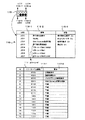
ここでは、各ディスクアレイ装置41,42,43に装着されている現在の保守用端末の状態、エラーコードを表示させる。表示方法の例を図11に示す。図11において、発光ダイオード(LED)115の115−0で示すLED0〜115−3で示すLED3、115−4で示すLED4〜115−7で示すLED7の点灯表示に対応して表116で示す意味116−2及び状態116−3が割り当てられている。
As a third embodiment, a case where status display and error code lighting for each status are performed will be described.
Here, the status of the current maintenance terminal attached to each of the
表116において、LED0の点灯は保守端末起動中を意味し、保守端末起動時のオン状態である。LED1の点灯はモディファイモードを意味し、モディファイモード時のオン状態である。LED2の点灯はウエブコンソール使用可能を意味し、使用可能時のオン状態である。LED3の点灯は保守端末異常検出を意味し、検出時のオン状態である。LED4の点灯はエラーコードビット0(MSB)を意味する。LED5の点灯はエラーコードビット1を意味する。LED6の点灯はエラーコードビット2を意味する。LED7の点灯はエラーコードビット3(LSB)を意味する。
In Table 116, lighting of LED0 means that the maintenance terminal is being activated, and is in the ON state when the maintenance terminal is activated. The lighting of the
エラーコードビット117において、「0000」は正常動作中を意味する。「0001」は強制初期化中を意味する。「0010」はバックグラウンド異常検出を意味する。「0011」はウエブコンソール初期化失敗を意味する。
In the
これにより、複数のエラー要因がある場合はコードを1秒間隔で連続表示する。操作用パーソナルコンピュータ(PC)45からネットワーク44を介して各ディスクアレイ装置へのサーチによるブロードキャストに対する返信が無い場合に保守用端末のタスクが正常であることを確認できる。
Thereby, when there are a plurality of error factors, the codes are continuously displayed at intervals of 1 second. When there is no reply to the broadcast by the search from the operation personal computer (PC) 45 to each disk array device via the
以下に、LEDの制御仕様を説明する。
保守用端末の起動が終了したときにLED0が点灯するようにディスクアレイ装置によりLED0が制御される。このランプが点灯すればログインして保守用端末を使用可能になる。
Below, the control specification of LED is demonstrated.
The LED0 is controlled by the disk array device so that the LED0 is lit when the activation of the maintenance terminal is completed. When this lamp is lit, you can log in and use the maintenance terminal.
LED1は、保守用端末がモディファイモードに変更したときに点灯するようにディスクアレイ装置によりLED1が制御される。ビューモードに戻したら消灯するように制御される。
The
LED2は、ウエブアクセス準備プロセスがレディーになったときに点灯するようにディスクアレイ装置によりLED2が制御される。この状態は、ウエブコンソールがログイン可能な状態である。リフレッシュ中はLED2消灯するように制御され、再度レディーになったときに点灯するようにする制御される。
The
LED4〜LED7によるエラーコード表示では、エラーを検出したアプリケーションが外部IO制御タスクに対してエラーコードを通知するようにディスクアレイ装置によりLED4〜LED7が制御される。外部IO制御タスクは通知されたエラーコードを保守用端末内に記憶しLED4〜LED7により表示する。複数のエラーコードが報告された場合はそれらのエラーコードを一定間隔で連続表示する。エラーコードは4ビットで0〜15までとする。
In the error code display by the
また、第4の実施の形態例として、接続確認を行う場合を説明する。
図4に示した操作用パーソナルコンピュータ(PC)45からネットワーク44を介して各ディスクアレイ装置41,42,43に装着されている保守用端末に対してリモート接続による接続の接続確認を行う。ディスクアレイ装置同士はネットワーク44(LAN)で接続されており、複数のディスクアレイ装置が接続されている。保守時にそのネットワーク44(LAN)への接続ケーブルを抜き、ディスクアレイ装置一台のみと通信することも可能であるが、保守中にディスクアレイ装置同士のネットワーク44(LAN)を切断することは他の装置のエラー発生時に障害通知が送信不可となる。また、数十台のディスクアレイ装置に対して保守作業を行う場合には、1台ごとに操作端末を接続し直してネットワーク44(LAN)接続を変更するよりも、全てのディスクアレイ装置と接続できる操作用パーソナルコンピュータ(PC)45を使用して保守を行う方が作業量を少なくでき、誤りがない。
In addition, as a fourth embodiment, a case where connection confirmation is performed will be described.
The operation personal computer (PC) 45 shown in FIG. 4 confirms connection by remote connection to the maintenance terminal mounted on each of the
図2は、本発明に関わるLEDを用いた接続確認を行う手順を示した図である。
図2において、まず、操作用パーソナルコンピュータ(PC)45をネットワーク44(LAN)に接続し(ステップS1)、操作用パーソナルコンピュータ(PC)45からネットワーク44(LAN)を介してブロードキャスト送信により接続確認のためのサーチを実行する(ステップS2)。操作用パーソナルコンピュータ(PC)45は、各ディスクアレイ装置41,42,43から製造番号情報を受信すると(ステップS3)、IPアドレス及び製造番号を指定して接続を実行する(ステップS4)。
FIG. 2 is a diagram showing a procedure for performing connection confirmation using an LED according to the present invention.
In FIG. 2, first, an operation personal computer (PC) 45 is connected to the network 44 (LAN) (step S1), and the connection is confirmed by broadcast transmission from the operation personal computer (PC) 45 via the network 44 (LAN). A search for is performed (step S2). When the operation personal computer (PC) 45 receives the production number information from each of the
ここで、操作用パーソナルコンピュータ(PC)45から各ディスクアレイ装置41,42,43に対してリモート接続を実行し(ステップS5)、操作用パーソナルコンピュータ(PC)45のディスプレイ画面に指定した各ディスクアレイ装置41,42,43の接続状態を示すLEDパターンの表示をして(ステップS6)、各ディスクアレイ装置41,42,43の接続状態を示すLED点灯パターンの確認をする(ステップS7)。実際の各ディスクアレイ装置41,42,43の保守用端末のLED点灯パターンと操作用パーソナルコンピュータ(PC)45のディスプレイ画面のLED点灯パターンとを比較して(ステップS8)、一致すればディスクアレイ装置と接続が成立し(ステップS9)、一致しなければ装置と接続が成立しない(ステップS10)。
Here, a remote connection is executed from the operation personal computer (PC) 45 to each
上述したように図2に示す手順でリモート接続を行う際に、図3に示す操作用パーソナルコンピュータ(PC)45から保守端末へ接続を行う画面31上で、IPアドレスや製造番号のリストに基づいて接続を行うが、IPアドレスや製造番号を誤って認識していると、意図したものとは異なる接続が行われる。例えば、ディスクアレイ装置にIPアドレスと製造番号を示すラベルが貼ってあり、そのラベルが間違って貼られている状況などが考えられる。これにより、ディスクアレイ装置の保守端末上のLEDにネットワーク44(LAN)内での個別パターンの点灯を行い、また、操作用パーソナルコンピュータ(PC)45の画面にも同じパターンを表示することにより、その目視確認によって接続確認を行うことができる。
As described above, when the remote connection is performed according to the procedure shown in FIG. 2, on the
接続の確認状態を図4に示す。図4においては、操作用パーソナルコンピュータ(PC)45の画面に表示されるディスクアレイ装置43の接続状態を示すLED点灯パターン「2」とディスクアレイ装置43の保守用端末のLED点灯パターン「2」とが一致して、接続確認を目視により行うことができる例を示している。
これは部品交換を要する保守設定において、違うビルなど遠隔から交換設定を行い、別の保守員が現場で部品交換のみを行う際にも、このようにしてLEDパターンを確認することでディスクアレイ装置を誤りなく選択することができる。
A connection confirmation state is shown in FIG. In FIG. 4, the LED lighting pattern “2” indicating the connection state of the
This is because in maintenance settings that require parts replacement, the disk array device can be set up by remotely checking the LED pattern in this way, even when another part of the maintenance department only performs part replacement on-site. Can be selected without error.
また、第5の実施の形態例として、グループID点灯を行う場合を説明する。
複数台のディスクアレイ装置に対して、いくつかのグループに分けて設定を行う際のグループ分け確認を行う。複数のディスクアレイ装置への設定を同時に行うことは、一台ごとにリモート接続して設定するよりも手間がかからず、設定ミスが起こらない。しかし、ディスクアレイ装置を選択する際にIPアドレスと製造番号だけでは誤認が発生する恐れがある。そのため、これにより、操作用パーソナルコンピュータ(PC)45から複数台のディスクアレイ装置への設定時に設定対象のディスクアレイ装置の保守端末にはあるLEDパターン点灯の要求を行い、それ以外のディスクアレイ装置の保守端末にはLED消灯の要求を行い、目視確認することで設定対象の確認を一度に行うことができる。
In addition, as a fifth embodiment, a case where group ID lighting is performed will be described.
Grouping confirmation is performed when setting is performed for a plurality of disk array devices divided into several groups. Setting multiple disk array devices at the same time is less time-consuming and setting error than setting by connecting each unit remotely. However, when selecting a disk array device, there is a risk of misidentification only with the IP address and the serial number. For this reason, when a setting is made from a personal computer for operation (PC) 45 to a plurality of disk array devices, an LED pattern lighting request is made at the maintenance terminal of the disk array device to be set, and the other disk array devices The maintenance terminal is requested to turn off the LED, and the setting target can be confirmed at a time by visual confirmation.
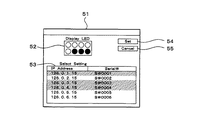
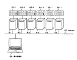
このときのグループ設定を行う設定画面を図5、接続図を図6、保守員の操作と装置の動作を図7に示す。図5において、グループ設定を行う設定画面51には、設定対象のディスクアレイ装置の保守端末におけるLED点灯パターン52と、このとき選択設定されているディスクアレイ装置のIPアドレスと製造番号53と、設定キー54及び解消キー55が表示される。また、図6において、操作用端末68からネットワーク67を介して、設定対象のディスクアレイ装置61,63,64の保守端末にはLEDパターン点灯「1」の要求を行い、それ以外のディスクアレイ装置62,65,66の保守端末にはLED消灯の要求を行う例を示している。
FIG. 5 shows a setting screen for performing group setting at this time, FIG. 6 shows a connection diagram, and FIG. 7 shows the operation of the maintenance staff and the operation of the apparatus. In FIG. 5, the
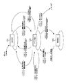
図7において、保守員操作側では、ディスクアレイ装置の同時設定を開始すると(ステップS11)、設定条件を決定し(ステップS12)、接続確認の送信により接続中のディスクアレイ装置を検出する(ステップS13)。このとき、ディスクアレイ装置動作側では、接続確認を受信して、IPアドレスと製造番号を返信する(ステップS21)。保守員操作側では、設定を実行するディスクアレイ装置を選択して(ステップS14)、膳装置へ選択有無とLEDパターンを送信する(ステップS15)。 In FIG. 7, when the maintenance personnel operation side starts simultaneous setting of the disk array device (step S11), the setting condition is determined (step S12), and the connected disk array device is detected by transmitting a connection confirmation (step S12). S13). At this time, the disk array device operation side receives the connection confirmation and returns the IP address and the manufacturing number (step S21). On the maintenance staff operation side, the disk array device to be set is selected (step S14), and the presence / absence of the selection and the LED pattern are transmitted to the saddle device (step S15).
このとき、ディスクアレイ装置動作側では、受信したLEDパターンを点灯して、未選択であれば消灯する(ステップS22)。保守員操作側では、ディスクアレイ装置のLED点灯パターンを目視確認して(ステップS16)、設定条件の送信により設定を実行する(ステップS17)。このとき、ディスクアレイ装置動作側では、設定を実行し、終了後に設定結果を送信する(ステップS23)。保守員操作側では、設定結果を確認して、設定を終了する(ステップS18)。ディスクアレイ装置動作側では、LED点灯を元に戻す(ステップS24)。 At this time, the disk array device operating side turns on the received LED pattern, and turns it off if not selected (step S22). On the maintenance personnel operation side, the LED lighting pattern of the disk array device is visually confirmed (step S16), and the setting is executed by transmitting the setting conditions (step S17). At this time, the disk array device operation side executes the setting, and transmits the setting result after completion (step S23). On the maintenance operator side, the setting result is confirmed, and the setting is completed (step S18). On the disk array device operating side, the LED lighting is restored (step S24).
また、第6の実施の形態例として、稼動端末と待機端末の区別を行う場合を説明する。
上述したように、ディスクアレイ装置内で保守端末は図13に示す稼動用の保守用端末131及び待機用の保守用端末132の2台実装されており、稼動用の保守用端末131に障害が発生すると、待機用の保守用端末132が稼動用の保守用端末131に置き換わる。待機用の保守用端末132は常に電源オン状態であり、通常どちらが稼動用の保守用端末131であるか区別はつかない。そこで待機用の保守用端末132には通常接続確認の個別パターンのLED点灯を行わないことで区別するようにすることにより、稼動端末と待機端末の区別を容易に行うことができる。
In addition, as a sixth embodiment, a case will be described in which an active terminal and a standby terminal are distinguished.
As described above, two maintenance terminals are installed in the disk array apparatus, namely, the
図10は、本発明に関わるLED表示の状態遷移図を示した図である。図10において、スタート104して、LED消灯101に状態遷移する。稼動/待機PC105−1のイベントに対して固有LEDパターン点灯105−2の動作を行った後に、イベント待ち102に状態遷移する。
FIG. 10 is a diagram showing a state transition diagram of LED display according to the present invention. In FIG. 10, the process starts at 104 and the state transitions to the LED off 101. After the operation of the specific LED pattern lighting 105-2 is performed for the event of the operation / standby PC 105-1, the state transitions to the
このとき、ジャンパコネクタ(JP2)セット106−1のイベントに対してIPアドレス表示106−2の動作を行った後に、LED消灯101に状態遷移する。また、このとき、ジャンパコネクタ(JP3)セット107−1のイベントに対して状態/エラーコード表示107−2の動作を行った後に、状態表示103に状態遷移する。このとき、ジャンパコネクタ(JP3)除去108−1のイベントの後に、稼動/待機PC109−1のイベントに対して固有LEDパターン点灯/消灯109−2の動作を行った後に、イベント待ち102に状態遷移する。
At this time, after the operation of the IP address display 106-2 is performed for the event of the jumper connector (JP2) set 106-1, the state transitions to the
このとき、LED点灯セット110−1のイベントに対してLED点灯110−2の動作を行った後に、イベント待ち102に戻る。また、このとき、LED消灯セット112−1のイベントに対してLED消灯及びリセット112−2の動作を行った後に、LED消灯101に状態遷移する。また、このとき、切替指示111−1のイベントに対して稼動/待機切替111−2の動作を行った後に、LED消灯101に状態遷移する。また、このとき、終了イベント113−1に対してスレッド終了113−2の動作を行った後に、終了114する。
At this time, after performing the operation of the LED lighting 110-2 for the event of the LED lighting set 110-1, the process returns to the event waiting 102. At this time, after the LED extinguishing and reset 112-2 operations are performed for the event of the LED extinguishing set 112-1, the state transitions to the LED extinguishing 101. At this time, after the operation of the operation / standby switching 111-2 is performed for the event of the switching instruction 111-1, the state transitions to the
また、上述した実施の形態に示した導通用のジャンパピンが挿入されるジャンパコネクタ及び発光ダイオードに限らず、スイッチ及び液晶パネルを適用してもよい。 Further, not only the jumper connector and the light emitting diode jumpers electrically-class shown in the embodiment described above is inserted, may be applied to switches and a liquid crystal panel.
1…LED、2…ジャンパコネクタ(JP1)、3…ジャンパコネクタ(JP2)、4…ジャンパコネクタ(JP3)、31…操作端末から保守端末へ接続を行う画面、41〜43…ディスクアレイ装置、41−1〜43−1…保守端末の発光ダイオード(LED)、44…ネットワーク、45…操作用パーソナルコンピュータ(PC)、46…操作用パーソナルコンピュータ(PC)の画面、47…操作用パーソナルコンピュータ(PC)画面上のLED表示
DESCRIPTION OF
Claims (7)
導通ピンを挿入又は挿出することにより、上記ディスクアレイ装置の設定の第1の状態と第2の状態とを選択的に切り替え可能とする複数の設定端子と、
上記設定の第1の状態又は第2の状態に対応して複数の表示素子の点灯及び消灯による状態表示を可能とする発光表示素子とを備え、
上記発光表示素子に上記設定の第1の状態又は第2の状態に対応する個別パターンの点灯を行うと共に、上記ネットワークに接続された操作用端末の画面にも上記個別パターンと同じパターンを表示させることを特徴とする
ディスクアレイ装置の保守用端末。 Mounted on the attached disk array apparatus to a network, the maintenance terminal of the disk array apparatus to perform the settings of the disk array apparatus,
By insert or挿出 conduction pin, a plurality of setting pins to the first and second states of the setting of the disk array device selectively switchable,
A light-emitting display element capable of displaying a state by turning on and off a plurality of display elements corresponding to the first state or the second state of the setting ,
The individual pattern corresponding to the first state or the second state of the setting is turned on on the light emitting display element, and the same pattern as the individual pattern is displayed on the screen of the operation terminal connected to the network. A maintenance terminal for a disk array device.
上記複数の設定端子に対する上記導通ピンの挿入又は挿出により、上記設定の第1の状態又は第2の状態に対応する上記ネットワーク上の識別番号を示すIPアドレスを強制的に初期設定に戻し、上記ディスクアレイ装置に対する入力操作を許可するパスワードを初期化することを特徴とする
ディスクアレイ装置の保守用端末。 The maintenance terminal for the disk array device according to claim 1,
By the plurality of set insertion or挿出 of the conductive pin into the pin, back forcibly initialize the IP address indicating the identification number on the network corresponding to the first state or the second state of the set A maintenance terminal for a disk array device, wherein a password for permitting an input operation to the disk array device is initialized.
上記複数の設定端子に対する上記導通ピンの挿入又は挿出により、上記発光表示素子に現在の上記設定の第1の状態又は第2の状態又はエラーコードを表示させることを特徴とする
ディスクアレイ装置の保守用端末。 The maintenance terminal for the disk array device according to claim 1,
The insertion or挿出 of the conductive pins with respect to the plurality of setting terminals, disk array and wherein the displaying the first state or the second state or the error code for the current of the set in the light emitting display device Maintenance terminal.
複数台の上記ディスクアレイ装置に対して、いくつかのグループに分けて設定を行う際に、上記操作用端末からの要求に応じて、設定対象のディスクアレイ装置の上記発光表示素子にはあるパターン点灯を行い、それ以外のディスクアレイ装置の上記発光表示素子には消灯を行うようにしたことを特徴とする
ディスクアレイ装置の保守用端末。 The maintenance terminal for the disk array device according to claim 1,
Against a plurality of the disk array apparatus, when setting is divided into several groups, in response to a request from the upper Kimisao action terminal, located in the light emitting display device of the disk array device to be set A maintenance terminal for a disk array device, wherein the pattern is turned on and the light emitting display elements of the other disk array devices are turned off.
上記ディスクアレイ装置内に保守用端末が2台設けられ、上記2台の保守用端末のうち稼動端末に障害が発生すると待機端末が上記稼動端末に置き換わり、上記待機端末は常に電源オン状態であって上記待機端末の上記発光表示素子には消灯を行わないことを特徴とする
ディスクアレイ装置の保守用端末。 The maintenance terminal for the disk array device according to claim 1,
Two maintenance terminals are provided in the disk array device, and when a failure occurs in the active terminal of the two maintenance terminals, the standby terminal is replaced with the active terminal, and the standby terminal is always in a power-on state. The disk array device maintenance terminal is characterized in that the light emitting display element of the standby terminal is not turned off.
上記複数の設定端子は導通用のジャンパピンが挿入されるジャンパコネクタであり、上記発光表示素子は発光ダイオードであることを特徴とする
ディスクアレイ装置の保守用端末。 The maintenance terminal for the disk array device according to claim 1,
A maintenance terminal for a disk array device, wherein the plurality of setting terminals are jumper connectors into which jumper pins for conduction are inserted, and the light emitting display element is a light emitting diode.
上記複数の設定端子はスイッチであり、上記発光表示素子は液晶パネルであることを特徴とする
ディスクアレイ装置の保守用端末。 The maintenance terminal for the disk array device according to claim 1,
The maintenance terminal for a disk array device, wherein the plurality of setting terminals are switches, and the light emitting display element is a liquid crystal panel.
Priority Applications (3)
| Application Number | Priority Date | Filing Date | Title |
|---|---|---|---|
| JP2004069305A JP4454346B2 (en) | 2004-03-11 | 2004-03-11 | Disk array system maintenance terminal |
| US10/849,120 US7225328B2 (en) | 2004-03-11 | 2004-05-20 | Maintenance terminal of disk array device |
| EP04257109A EP1585027A1 (en) | 2004-03-11 | 2004-11-17 | Maintenance terminal of disk array device |
Applications Claiming Priority (1)
| Application Number | Priority Date | Filing Date | Title |
|---|---|---|---|
| JP2004069305A JP4454346B2 (en) | 2004-03-11 | 2004-03-11 | Disk array system maintenance terminal |
Publications (3)
| Publication Number | Publication Date |
|---|---|
| JP2005258798A JP2005258798A (en) | 2005-09-22 |
| JP2005258798A5 JP2005258798A5 (en) | 2007-03-08 |
| JP4454346B2 true JP4454346B2 (en) | 2010-04-21 |
Family
ID=34909394
Family Applications (1)
| Application Number | Title | Priority Date | Filing Date |
|---|---|---|---|
| JP2004069305A Expired - Fee Related JP4454346B2 (en) | 2004-03-11 | 2004-03-11 | Disk array system maintenance terminal |
Country Status (3)
| Country | Link |
|---|---|
| US (1) | US7225328B2 (en) |
| EP (1) | EP1585027A1 (en) |
| JP (1) | JP4454346B2 (en) |
Families Citing this family (6)
| Publication number | Priority date | Publication date | Assignee | Title |
|---|---|---|---|---|
| CN100581172C (en) * | 2006-04-19 | 2010-01-13 | 杭州华三通信技术有限公司 | Method for accessing object magnetic dish and system for extensing disk content |
| JP4906832B2 (en) * | 2008-10-28 | 2012-03-28 | 株式会社日立製作所 | Computer product maintenance support system |
| US8868900B2 (en) | 2009-02-24 | 2014-10-21 | Hewlett-Packard Development Company, L.P. | Method and system to lower power consumption |
| JP6039464B2 (en) * | 2013-02-28 | 2016-12-07 | アズビル株式会社 | Device management apparatus and device management method |
| KR20180095766A (en) * | 2017-02-17 | 2018-08-28 | 삼성전자주식회사 | Storage device |
| JP6693540B2 (en) * | 2018-07-31 | 2020-05-13 | 横河電機株式会社 | Device, method and program |
Family Cites Families (19)
| Publication number | Priority date | Publication date | Assignee | Title |
|---|---|---|---|---|
| FR2561428B1 (en) * | 1984-03-16 | 1986-09-12 | Bull Sa | DISC MEMORY RECORDING METHOD AND DISC MEMORY SYSTEM |
| US5148432A (en) * | 1988-11-14 | 1992-09-15 | Array Technology Corporation | Arrayed disk drive system and method |
| JPH0823802B2 (en) * | 1991-11-13 | 1996-03-06 | 富士通株式会社 | Array disk device status display method |
| JP2548480B2 (en) * | 1992-02-10 | 1996-10-30 | 富士通株式会社 | Disk device diagnostic method for array disk device |
| US5717570A (en) * | 1995-10-06 | 1998-02-10 | Elonex I.P. Holdings Ltd. | Enhanced mini-tower computer architecture |
| US6076142A (en) * | 1996-03-15 | 2000-06-13 | Ampex Corporation | User configurable raid system with multiple data bus segments and removable electrical bridges |
| US6240058B1 (en) * | 1996-07-11 | 2001-05-29 | Nsm Aktiengesellschaft | Disk-changing unit with modular design |
| JPH10187358A (en) | 1996-12-25 | 1998-07-14 | Hitachi Ltd | Disk array device |
| US6654382B1 (en) * | 1998-10-26 | 2003-11-25 | Hewlett-Packard Developmemt Company, L.P. | Network device with logical-address learn mode |
| JP3904386B2 (en) | 2000-11-20 | 2007-04-11 | 株式会社日立製作所 | Subsystem management method |
| GB2407896B (en) | 2001-01-31 | 2005-06-22 | Hewlett Packard Co | Storage apparatus |
| US20020142765A1 (en) * | 2001-03-30 | 2002-10-03 | Rhoads Monte J. | Network appliance wireless configuration interface |
| US6941357B2 (en) * | 2001-07-18 | 2005-09-06 | Dell Products L.P. | Fibre channel switching appliance |
| WO2003029985A1 (en) | 2001-10-03 | 2003-04-10 | Frits Olsen | System with cascade coupled discs for increased capacity and backup |
| JP4246979B2 (en) * | 2002-09-05 | 2009-04-02 | 株式会社日立製作所 | Device management system |
| US6809505B2 (en) * | 2002-09-26 | 2004-10-26 | Emc Corporation | Storage system and method of detecting an improper cable connection in the storage system |
| JP4371720B2 (en) * | 2003-06-27 | 2009-11-25 | 株式会社日立製作所 | Storage device system and storage system maintenance method |
| US8639866B2 (en) * | 2003-08-06 | 2014-01-28 | Hewlett-Packard Development Company, L.P. | Systems and methods for dividing a communications channel |
| JP2005182245A (en) * | 2003-12-17 | 2005-07-07 | Hitachi Ltd | Connection support method for disk array device |
-
2004
- 2004-03-11 JP JP2004069305A patent/JP4454346B2/en not_active Expired - Fee Related
- 2004-05-20 US US10/849,120 patent/US7225328B2/en not_active Expired - Fee Related
- 2004-11-17 EP EP04257109A patent/EP1585027A1/en not_active Withdrawn
Also Published As
| Publication number | Publication date |
|---|---|
| US7225328B2 (en) | 2007-05-29 |
| EP1585027A1 (en) | 2005-10-12 |
| US20050210207A1 (en) | 2005-09-22 |
| JP2005258798A (en) | 2005-09-22 |
Similar Documents
| Publication | Publication Date | Title |
|---|---|---|
| EP2128766B1 (en) | Electronic apparatus system having a plurality of rack-mounted electronic apparatuses, and a method for identifying electronic apparatus in electronic apparatus system | |
| US6188973B1 (en) | Automatic mapping, monitoring, and control of computer room components | |
| CN105700969B (en) | server system | |
| US7441083B2 (en) | Data storage device management system | |
| US7111084B2 (en) | Data storage network with host transparent failover controlled by host bus adapter | |
| TWI223142B (en) | System and method for displaying computer system status information | |
| US6867704B2 (en) | Bi-color light source for indicating status of information handling system | |
| US20020113714A1 (en) | IP-addressable light-emitting diode | |
| CN100538567C (en) | Programmable Logic Controller | |
| US20020188709A1 (en) | Console information server system and method | |
| JP4454346B2 (en) | Disk array system maintenance terminal | |
| NO336900B1 (en) | Control system for several dispersed localized lamp operating devices and method for initializing such control system | |
| CN102479140A (en) | Computer system and hard disk state display method | |
| JP2009129418A (en) | Disk controller and storage system | |
| CN101174996A (en) | Visual guidance and verification for interconnecting nodes | |
| CN101271420B (en) | Operating system hard disk recognition device | |
| US7259683B2 (en) | Rack | |
| JP4841163B2 (en) | Security terminal | |
| JP2005258798A5 (en) | ||
| US7424554B1 (en) | Method of and system for changing the address of a disk array enclosure | |
| CN215987289U (en) | Abnormal display device for server equipment | |
| JPH09101909A (en) | Parallel maintenance work guidance system | |
| CN101887287B (en) | Single-key multiple-power-switch control structure and method thereof | |
| JP2008166151A (en) | Lighting control system | |
| EP2981899B1 (en) | Cartridge interdependence switch |
Legal Events
| Date | Code | Title | Description |
|---|---|---|---|
| A521 | Request for written amendment filed |
Free format text: JAPANESE INTERMEDIATE CODE: A523 Effective date: 20070123 |
|
| A621 | Written request for application examination |
Free format text: JAPANESE INTERMEDIATE CODE: A621 Effective date: 20070123 |
|
| A977 | Report on retrieval |
Free format text: JAPANESE INTERMEDIATE CODE: A971007 Effective date: 20090603 |
|
| A131 | Notification of reasons for refusal |
Free format text: JAPANESE INTERMEDIATE CODE: A131 Effective date: 20090609 |
|
| A521 | Request for written amendment filed |
Free format text: JAPANESE INTERMEDIATE CODE: A523 Effective date: 20090716 |
|
| TRDD | Decision of grant or rejection written | ||
| A01 | Written decision to grant a patent or to grant a registration (utility model) |
Free format text: JAPANESE INTERMEDIATE CODE: A01 Effective date: 20100202 |
|
| A01 | Written decision to grant a patent or to grant a registration (utility model) |
Free format text: JAPANESE INTERMEDIATE CODE: A01 |
|
| A61 | First payment of annual fees (during grant procedure) |
Free format text: JAPANESE INTERMEDIATE CODE: A61 Effective date: 20100202 |
|
| FPAY | Renewal fee payment (event date is renewal date of database) |
Free format text: PAYMENT UNTIL: 20130212 Year of fee payment: 3 |
|
| R150 | Certificate of patent or registration of utility model |
Free format text: JAPANESE INTERMEDIATE CODE: R150 |
|
| FPAY | Renewal fee payment (event date is renewal date of database) |
Free format text: PAYMENT UNTIL: 20130212 Year of fee payment: 3 |
|
| FPAY | Renewal fee payment (event date is renewal date of database) |
Free format text: PAYMENT UNTIL: 20140212 Year of fee payment: 4 |
|
| LAPS | Cancellation because of no payment of annual fees |