JP4447140B2 - Motor stator - Google Patents
Motor stator Download PDFInfo
- Publication number
- JP4447140B2 JP4447140B2 JP2000281176A JP2000281176A JP4447140B2 JP 4447140 B2 JP4447140 B2 JP 4447140B2 JP 2000281176 A JP2000281176 A JP 2000281176A JP 2000281176 A JP2000281176 A JP 2000281176A JP 4447140 B2 JP4447140 B2 JP 4447140B2
- Authority
- JP
- Japan
- Prior art keywords
- motor stator
- connecting portion
- arc
- butting
- electric motor
- Prior art date
- Legal status (The legal status is an assumption and is not a legal conclusion. Google has not performed a legal analysis and makes no representation as to the accuracy of the status listed.)
- Expired - Lifetime
Links
Images


Description
【0001】
【発明の属する技術分野】
この発明は、空気調和機や冷凍機を用途とする圧縮機駆動用の電動機等に使用される電動機固定子に関するものである。
【0002】
【従来の技術】
図5、図6は、例えば特開平9−191588号公報に開示された従来の電動機固定子を示す図である。図5に示すように、複数のコア片101が薄肉連結部102を介して連結された磁性材料を所定の枚数積層されている。また、薄肉連結部102の両側には連結部突き合わせ面102a及び102bが位置している。また、101b及び101cは両端に位置する各コア片101の端部突き合わせ面で、連結部突き合わせ面102a、102bと同様の形状をなしている。
【0003】
上記のように構成された固定子において、各コア片101に巻線(図示省略)を巻き、図6に示すように各薄肉連結部102を折り曲げ、薄肉連結部102の両側に位置する連結部突き合わせ面102aと102bを突き合わせ、最終的に端部突き合わせ面101bと101cを突き合わせることにより環状に形成し、電動機固定子が形成される。
【0004】
【発明が解決しようとする課題】
従来の電動機固定子は上記のように構成されているので、環状に形成される際に端部突き合わせ面101b及び101cが半径方向に容易にずれ、固定子の機械的精度を保つことが困難ある。よって電動機として構成される際に磁性材料の磁気的性能が損なわれ、電動機の効率を悪化させたり、磁気的アンバランスが生じ運転中に振動や騒音が発生される問題点があった。
【0005】
また、上記説明では薄肉にて連結部を構成した例を挙げたが、それ以外の何らかの方法にて折り曲げ可能な構成をなしているものも同様の問題が発生する。
【0006】
また、連結部突き合わせ面102a及び102b、端部突き合わせ面101b及び101cの形状はストレートな形状なものの例をあげているが、円弧形状等で形成されている場合も同様の問題が発生する。
【0007】
この発明は上記のような問題点を解消するためになされたもので、電動機固定子の製造時に機械的精度を容易に確保することを可能とすることにより、電動機の効率悪化や振動、騒音を低減させることを目的とする。
【0008】
【課題を解決するための手段】
この発明に係る電動機固定子は、複数のコア片が連結部を介して連結された磁性材料を所定の枚数積層され、且つ、連結部の両側には連結部突き合わせ面が位置し、更に両端のコア片に端部突き合わせ面を有し、コア片に巻線が巻回された後、各連結部を折り曲げ、連結部突き合わせ面を突き合わせ、最終的に端部突き合わせ面同士を突き合わせることにより環状に形成される電動機固定子において、端部突き合わせ面の形状をくの字形状としたものである。
【0009】
また、連結部を薄肉で構成したものである。
【0010】
また、くの字形状の端部突き合わせ面は、第1の円弧と第2の円弧の2つの円弧の組み合わせより形成され、それぞれの円弧の中心は固定子中の何れかのコア片の連結部を折り曲げる際の回転中心と概略一致しているものである。
【0011】
また、端部突き合わせ面を突き合わせた際に、電動機固定子の外周側を先端とする突起部が形成され、且つ、突起部の先端は電動機固定子の外周よりも内側に位置するものである。
【0012】
【発明の実施の形態】
実施の形態1.
以下、この発明の実施の形態1を図面を参照して説明する。
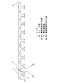
図1、2は実施の形態1を示す図で、図1は帯状の電動機固定子の平面図、図2は環状に形成された電動機固定子の平面図である。
図1において、1は磁性材料からなる板状のコア片で、2はコア片1に設けられた薄肉連結部である。1aはコア片1に設けられたティース部、2a及び2bは薄肉連結部2の両側に位置する連結部突き合わせ面である。1b及び1cは両端のコア片1の薄肉連結部2とは反対側に位置するくの字形状の端部突き合わせ面である。
【0013】
上記のように構成された電動機固定子の製造法を説明する。巻線(図示省略)がティース部1aに巻回された後、各コア片1は図2に示すように、各薄肉連結部2が折り曲げられ、連結部突き合わせ面2aと2bが突き合わされ、位置が決められ、最終的に両端の端部突き合わせ面1bと1cが突き合わされ環状に形成され、溶接等により固着され、巻線の端末線を結線することにより電動機固定子が形成される。
【0014】
上記のように構成されているので、各コア片1の位置関係が各連結部突き合わせ面2a及び2bと端部突き合わせ面1b及び1cにより決定される。端部突き合わせ面1b及び1cにおいては形状がくの字状であるため突き合わされた際、半径方向の動きが規制されるため電動機固定子の機械的精度は一意的に決まり、コア片1の打ち抜き等の精度を上げることにより容易に精度を確保することができる。
【0015】
本実施の形態では、連結部が薄肉で構成されているものを挙げたが、それ以外の何らかの方法で連結部を構成し、複数の展開されたコア片1が環状に形成できるものであっても同様の効果が得られる。
【0016】
実施の形態2.
以下、この発明の実施の形態2を図面を参照して説明する。
図3は実施の形態2を示す図で、環状に形成される直前の状態を示す電動機固定子の平面図である。
図3において、1は磁性材料からなる板状のコア片で、2はコア片1に設けられた薄肉連結部である。2a及び2bは薄肉連結部2の両側に位置する連結部突き合わせ面である。1b及び1cは両端のコア片1の薄肉連結部2とは反対側に位置するくの字形状の端部突き合わせ面である。
【0017】
端部突き合わせ面1b及び1cは、2つの円弧形状の第1の円弧1d及び第2の円弧1eで構成され、それぞれの円弧の中心は何れかのコア片1の薄肉連結部2が折り曲げられる際の回転中心と概略一致している。
【0018】
上記のように構成されているので、最終的に両端のコア片1を突き合わせる際の何れかのコア片1の薄肉連結部2の回転中心が第1の円弧1d及び第2の円弧1eの中心となっているため、その中心となっている薄肉連結部2を最後に折り曲げても、コア片1同士が干渉することなく、環状に形成することができる。
【0019】
よって折り曲げ工程の順番等の制約がなくなり、設備上の自由度を増すことができる。また、折り曲げ工程での干渉をなくすことができるので信頼性の高い電動機固定子の製造ができる。
【0020】
本実施の形態では、連結部が薄肉で構成されているものを挙げたが、それ以外の何らかの方法で連結部を構成し、複数の展開されたコア片1が環状に形成できるものであっても同様の効果が得られる。
【0021】
実施の形態3.
以下、この発明の実施の形態3を図面を参照して説明する。
図4は実施の形態3を示す図で、電動機固定子の一部を示す平面図である。
図4において、1は磁性材料からなる板状のコア片で、1b及び1cは両端のコア片1の薄肉連結部2とは反対側に位置するくの字形状の端部突き合わせ面である。3は端部突き合わせ面を突き合わせた際に形成される突起部で、電動機固定子の外周側を先端とする山形形状となっており、突起部3の先端は電動機固定子の外周よりも内側に位置している。
【0022】
上記のように構成されているので、最終的に両端のコア片1を突き合わせる際に突起部3の先端が外周側を向き、溶接にて端部突き合わせ面1b、1cを固着する際、平坦面や外周の円弧面に溶接する場合に比べ、アークが必要部分に飛びやすく安定した溶接ができる。
【0023】
【発明の効果】
この発明に係る電動機固定子は、端部突き合わせ面の形状をくの字形状としたので、各コア片の位置関係が各連結部突き合わせ面と端部突き合わせ面により決定され、端部突き合わせ面においては形状がくの字状であるため突き合わされた際、半径方向の動きが規制されるため電動機固定子の機械的精度は一意的に決まり、コア片の打ち抜き等の精度を上げることにより容易に精度を確保することができる。よって、機械的精度に起因する電磁音や振動を低減することができ、高密度な巻線を施した、高効率で低騒音、低振動な電動機固定子を容易に得ることができる。
【0024】
また、くの字形状の端部突き合わせ面は、第1の円弧と第2の円弧の2つの円弧の組み合わせより形成され、それぞれの円弧の中心は固定子中の何れかのコア片の連結部を折り曲げる際の回転中心と概略一致していることにより、最終的に両端のコア片を突き合わせる際のコア片の連結部の回転中心が第1の円弧及び第2の円弧の中心となっているためその中心となっている連結部を最後に折り曲げても、コア片同士が干渉することなく、環状に形成することができる。よって折り曲げ工程の順番等の制約がなくなり、設備上の自由度を増すことができる。また、折り曲げ工程での干渉をなくすことができる。よって、さらに組立性が良い、信頼性の高い電動機固定子を得ることができる。
【0025】
また、端部突き合わせ面を突き合わせた際に、電動機固定子の外周側を先端とする突起部が形成され、且つ、突起部の先端は電動機固定子の外周よりも内側に位置することにより、最終的に両端のコア片を突き合わせる際に突起部の先端が外周側を向き、溶接にて端部突き合わせ面を固着する際、平坦面や外周の円弧面に溶接した場合に比べ、アークが必要部分に飛びやすく安定的に溶接できる。よって、さらに組立性が良い、信頼性の高い電動機固定子を得ることができる。
【図面の簡単な説明】
【図1】 実施の形態1を示す図で、帯状の電動機固定子の平面図である。、図2は環状に形成された電動機固定子の平面図である。
における電動機固定子の平面図である。
【図2】 実施の形態1を示す図で、環状に形成された電動機固定子の平面図である。
【図3】 実施の形態2を示す図で、環状に形成される直前の状態を示す電動機固定子の平面図である。
【図4】 実施の形態3を示す図で、環状に形成された電動機固定子の一部を示す平面図である。
【図5】 従来の電動機固定子の平面図である。
【図6】 従来の電動機固定子の平面図である。
【符号の説明】
1 コア片、1a ティース部、1b 端部突き合わせ面、1c 端部突き合わせ面、1d 第1の円弧、1e 第2の円弧、2 薄肉連結部、2a 連結部突き合わせ面、2b 連結部突き合わせ面、3 突起部。[0001]
BACKGROUND OF THE INVENTION
The present invention relates to an electric motor stator used for an electric motor for driving a compressor for an air conditioner or a refrigerator.
[0002]
[Prior art]
5 and 6 are views showing a conventional electric motor stator disclosed in, for example, Japanese Patent Laid-Open No. 9-191588. As shown in FIG. 5, a predetermined number of magnetic materials in which a plurality of
[0003]
In the stator configured as described above, a winding (not shown) is wound around each
[0004]
[Problems to be solved by the invention]
Since the conventional motor stator is configured as described above, the
[0005]
Moreover, although the example which comprised the connection part with the thin wall was given in the said description, the same problem generate | occur | produces what has comprised the structure which can be bent by some other method.
[0006]
Moreover, although the example of the shape of the connection
[0007]
The present invention has been made to solve the above-described problems, and by making it possible to easily ensure mechanical accuracy during the manufacture of the motor stator, it is possible to reduce the efficiency of the motor, vibration, and noise. The purpose is to reduce.
[0008]
[Means for Solving the Problems]
In the motor stator according to the present invention, a predetermined number of magnetic materials in which a plurality of core pieces are connected via a connecting portion are laminated, and connecting portion abutting surfaces are located on both sides of the connecting portion, and further, The core piece has an end abutting surface, and after the winding is wound around the core piece, each connecting portion is bent, the connecting portion abutting surfaces are abutted, and finally the end abutting surfaces are abutted to form a ring In the electric motor stator formed in the above, the shape of the end butting surface is a dogleg shape.
[0009]
Further, the connecting portion is formed of a thin wall.
[0010]
Further, the U-shaped end butting surface is formed by a combination of two arcs of a first arc and a second arc, and the center of each arc is a connecting portion of any core piece in the stator. Is substantially coincident with the center of rotation when bending.
[0011]
In addition, when the end-butting surfaces are butted, a protrusion having the outer peripheral side of the motor stator as a tip is formed, and the tip of the protrusion is positioned inside the outer periphery of the motor stator.
[0012]
DETAILED DESCRIPTION OF THE INVENTION
1 and 2 are diagrams showing the first embodiment, in which FIG. 1 is a plan view of a belt-shaped motor stator, and FIG. 2 is a plan view of a motor stator formed in an annular shape.
In FIG. 1, 1 is a plate-like core piece made of a magnetic material, and 2 is a thin-walled connecting portion provided on the
[0013]
A method of manufacturing the motor stator configured as described above will be described. After the winding (not shown) is wound around the tooth portion 1a, each
[0014]
Since it is comprised as mentioned above, the positional relationship of each
[0015]
In the present embodiment, the connection portion is configured to be thin, but the connection portion is configured by some other method, and a plurality of deployed
[0016]
FIG. 3 is a diagram showing the second embodiment, and is a plan view of an electric motor stator showing a state immediately before being formed in an annular shape.
In FIG. 3, 1 is a plate-shaped core piece made of a magnetic material, and 2 is a thin-walled connecting portion provided on the
[0017]
The
[0018]
Since it is comprised as mentioned above, the rotation center of the
[0019]
Therefore, there are no restrictions on the order of the bending process, and the degree of freedom in equipment can be increased. Further, since interference in the bending process can be eliminated, a highly reliable motor stator can be manufactured.
[0020]
In the present embodiment, the connection portion is configured to be thin, but the connection portion is configured by some other method, and a plurality of deployed
[0021]
Embodiment 3 FIG.
Embodiment 3 of the present invention will be described below with reference to the drawings.
FIG. 4 is a diagram showing the third embodiment, and is a plan view showing a part of the motor stator.
In FIG. 4, 1 is a plate-shaped core piece made of a magnetic material, and 1b and 1c are dog-shaped end butting surfaces located on opposite sides of the thin-walled connecting
[0022]
Since it is configured as described above, when the
[0023]
【The invention's effect】
In the electric motor stator according to the present invention, since the shape of the end abutting surface is a U-shape, the positional relationship of each core piece is determined by each connecting portion abutting surface and the end abutting surface. Since the shape of the is a U-shaped, the radial movement is restricted when it is abutted, so the mechanical accuracy of the motor stator is uniquely determined, and it can be easily improved by increasing the accuracy of punching of the core piece etc. Can be secured. Therefore, electromagnetic noise and vibration due to mechanical accuracy can be reduced, and a high-efficiency, low-noise, low-vibration motor stator with high-density windings can be easily obtained.
[0024]
Further, the U-shaped end butting surface is formed by a combination of two arcs of a first arc and a second arc, and the center of each arc is a connecting portion of any core piece in the stator. The center of rotation of the connecting portion of the core pieces when the core pieces at both ends are finally brought into contact with each other is the center of the first arc and the second arc. Therefore, even if the connecting portion which is the center is bent at the end, the core pieces can be formed in an annular shape without interfering with each other. Therefore, there are no restrictions on the order of the bending process, and the degree of freedom in equipment can be increased. Further, interference in the bending process can be eliminated. Therefore, it is possible to obtain a highly reliable electric motor stator with better assembly.
[0025]
In addition, when the end butting surfaces are butted, a protrusion having the outer peripheral side of the motor stator as a tip is formed, and the tip of the protrusion is positioned on the inner side of the outer periphery of the motor stator. When the core pieces at both ends are generally abutted, the tip of the protrusion faces the outer peripheral side, and when fixing the end abutting surface by welding, an arc is required compared to welding to a flat surface or an arcuate surface of the outer periphery It is easy to fly to the part and can be welded stably. Therefore, it is possible to obtain a highly reliable electric motor stator with better assembly.
[Brief description of the drawings]
FIG. 1 shows the first embodiment and is a plan view of a belt-like electric motor stator. FIG. 2 is a plan view of a motor stator formed in an annular shape.
It is a top view of the electric motor stator in FIG.
FIG. 2 shows the first embodiment, and is a plan view of a motor stator formed in an annular shape.
FIG. 3 shows the second embodiment and is a plan view of an electric motor stator showing a state immediately before being formed in an annular shape.
FIG. 4 shows the third embodiment, and is a plan view showing a part of an electric motor stator formed in an annular shape.
FIG. 5 is a plan view of a conventional motor stator.
FIG. 6 is a plan view of a conventional electric motor stator.
[Explanation of symbols]
DESCRIPTION OF
Claims (3)
前記くの字形状の端部突き合わせ面は、第1の円弧と第2の円弧の2つの円弧の組み合わせより形成され、それぞれの円弧の中心は固定子中の何れかのコア片の連結部を折り曲げる際の回転中心と概略一致していることを特徴とする電動機固定子。 A predetermined number of magnetic materials in which a plurality of core pieces are connected via a connecting portion are stacked, and connecting portion abutting surfaces are located on both sides of the connecting portion, and further, end core abutting surfaces are provided on the core pieces at both ends. Then, after the winding is wound on the core piece, in the electric motor stator formed in an annular shape by bending each connecting portion, butting the connecting portion butting surfaces, and finally butting the end butting surfaces together, The shape of the end butting surface is a dogleg shape ,
The U-shaped end butting surface is formed by a combination of two arcs of a first arc and a second arc, and the center of each arc is a connecting portion of any core piece in the stator. An electric motor stator characterized by being substantially coincident with a center of rotation at the time of bending.
Priority Applications (7)
| Application Number | Priority Date | Filing Date | Title |
|---|---|---|---|
| JP2000281176A JP4447140B2 (en) | 2000-09-18 | 2000-09-18 | Motor stator |
| TW090103126A TW508891B (en) | 2000-02-21 | 2001-02-13 | Stator iron core of electric motor, manufacturing method thereof, electric motor, and compresor |
| US09/783,976 US20010030483A1 (en) | 2000-02-21 | 2001-02-16 | Stator iron core of electric motor, manufacturing method thereof, electric motor, and compressor |
| KR10-2001-0008315A KR100401083B1 (en) | 2000-02-21 | 2001-02-20 | Stator iron core of electric motor, manufacturing method thereof, electric motor, and compressor |
| CNB011028882A CN1162952C (en) | 2000-02-21 | 2001-02-21 | Motor stator-core and its producing method, and electric motor and compressor |
| US10/247,474 US6858964B2 (en) | 2000-02-21 | 2002-09-20 | Stator iron core of electric motor, manufacturing method thereof, electric motor, and compressor |
| US10/247,492 US6856064B2 (en) | 2000-02-21 | 2002-09-20 | Stator iron core of electric motor, manufacturing method thereof, electric motor, and compressor |
Applications Claiming Priority (1)
| Application Number | Priority Date | Filing Date | Title |
|---|---|---|---|
| JP2000281176A JP4447140B2 (en) | 2000-09-18 | 2000-09-18 | Motor stator |
Publications (3)
| Publication Number | Publication Date |
|---|---|
| JP2002095193A JP2002095193A (en) | 2002-03-29 |
| JP2002095193A5 JP2002095193A5 (en) | 2006-12-07 |
| JP4447140B2 true JP4447140B2 (en) | 2010-04-07 |
Family
ID=18765875
Family Applications (1)
| Application Number | Title | Priority Date | Filing Date |
|---|---|---|---|
| JP2000281176A Expired - Lifetime JP4447140B2 (en) | 2000-02-21 | 2000-09-18 | Motor stator |
Country Status (1)
| Country | Link |
|---|---|
| JP (1) | JP4447140B2 (en) |
Families Citing this family (3)
| Publication number | Priority date | Publication date | Assignee | Title |
|---|---|---|---|---|
| CN1315241C (en) | 2003-04-25 | 2007-05-09 | 日本电产株式会社 | Motor |
| JP5260951B2 (en) * | 2007-12-13 | 2013-08-14 | 三菱電機株式会社 | Laminated fixed iron core |
| WO2012105261A1 (en) * | 2011-02-03 | 2012-08-09 | パナソニック株式会社 | Motor stator and motor |
-
2000
- 2000-09-18 JP JP2000281176A patent/JP4447140B2/en not_active Expired - Lifetime
Also Published As
| Publication number | Publication date |
|---|---|
| JP2002095193A (en) | 2002-03-29 |
Similar Documents
| Publication | Publication Date | Title |
|---|---|---|
| KR100401083B1 (en) | Stator iron core of electric motor, manufacturing method thereof, electric motor, and compressor | |
| EP2026448B1 (en) | Split core and manufacturing method of the same, and stator core | |
| JP3786664B2 (en) | Rotating electrical machine core manufacturing method | |
| WO2010047098A1 (en) | Dual rotor motor and manufacturing method therefor | |
| JP5603437B2 (en) | Laminated iron core for rotating electrical machine and method for manufacturing the same | |
| US7239059B2 (en) | Stator of rotating electric machine and manufacturing method of the stator | |
| JPH08196061A (en) | Laminated core for stator | |
| WO2005086318A1 (en) | Armature core for dynamo-electric machine | |
| JP2004180383A (en) | Stator and its manufacturing method | |
| JP3379461B2 (en) | Core member laminating mold apparatus, core member laminating method and electric motor | |
| JP4447140B2 (en) | Motor stator | |
| JP3607849B2 (en) | Electric motor stator core | |
| JP3056738B1 (en) | Manufacturing method of condenser motor stator | |
| JP3754404B2 (en) | Structure of reciprocating motor and manufacturing method thereof | |
| JP3439658B2 (en) | Iron core | |
| JP4057406B2 (en) | Stator core, core sheet manufacturing method, and stator manufacturing method | |
| JP3515912B2 (en) | Motor stator | |
| WO2008072443A1 (en) | Electric motor stator | |
| JPH08205434A (en) | Laminated core for stator | |
| JP2002118992A (en) | Stator of rotating electric machine and its manufacturing method | |
| WO2012114428A1 (en) | Unit core of rotating electrical machine | |
| JP3576120B2 (en) | Stator core and rotary electric motor using this stator core | |
| JPH08126231A (en) | Stator of motor | |
| JP3735343B2 (en) | Armature core for rotating electrical machines | |
| JP2002247786A (en) | Manufacturing method of motor and motor stator |
Legal Events
| Date | Code | Title | Description |
|---|---|---|---|
| RD04 | Notification of resignation of power of attorney |
Free format text: JAPANESE INTERMEDIATE CODE: A7424 Effective date: 20040517 |
|
| RD04 | Notification of resignation of power of attorney |
Free format text: JAPANESE INTERMEDIATE CODE: A7424 Effective date: 20041018 |
|
| A521 | Written amendment |
Free format text: JAPANESE INTERMEDIATE CODE: A523 Effective date: 20061020 |
|
| A621 | Written request for application examination |
Free format text: JAPANESE INTERMEDIATE CODE: A621 Effective date: 20061020 |
|
| A977 | Report on retrieval |
Free format text: JAPANESE INTERMEDIATE CODE: A971007 Effective date: 20090603 |
|
| A131 | Notification of reasons for refusal |
Free format text: JAPANESE INTERMEDIATE CODE: A131 Effective date: 20090616 |
|
| A521 | Written amendment |
Free format text: JAPANESE INTERMEDIATE CODE: A523 Effective date: 20090807 |
|
| TRDD | Decision of grant or rejection written | ||
| A01 | Written decision to grant a patent or to grant a registration (utility model) |
Free format text: JAPANESE INTERMEDIATE CODE: A01 Effective date: 20100119 |
|
| A01 | Written decision to grant a patent or to grant a registration (utility model) |
Free format text: JAPANESE INTERMEDIATE CODE: A01 |
|
| A61 | First payment of annual fees (during grant procedure) |
Free format text: JAPANESE INTERMEDIATE CODE: A61 Effective date: 20100120 |
|
| FPAY | Renewal fee payment (event date is renewal date of database) |
Free format text: PAYMENT UNTIL: 20130129 Year of fee payment: 3 |
|
| R150 | Certificate of patent or registration of utility model |
Ref document number: 4447140 Country of ref document: JP Free format text: JAPANESE INTERMEDIATE CODE: R150 Free format text: JAPANESE INTERMEDIATE CODE: R150 |
|
| FPAY | Renewal fee payment (event date is renewal date of database) |
Free format text: PAYMENT UNTIL: 20130129 Year of fee payment: 3 |
|
| R250 | Receipt of annual fees |
Free format text: JAPANESE INTERMEDIATE CODE: R250 |
|
| R250 | Receipt of annual fees |
Free format text: JAPANESE INTERMEDIATE CODE: R250 |
|
| R250 | Receipt of annual fees |
Free format text: JAPANESE INTERMEDIATE CODE: R250 |
|
| R250 | Receipt of annual fees |
Free format text: JAPANESE INTERMEDIATE CODE: R250 |
|
| R250 | Receipt of annual fees |
Free format text: JAPANESE INTERMEDIATE CODE: R250 |
|
| EXPY | Cancellation because of completion of term |