JP4444487B2 - Clock movement with generator - Google Patents
Clock movement with generator Download PDFInfo
- Publication number
- JP4444487B2 JP4444487B2 JP2000369520A JP2000369520A JP4444487B2 JP 4444487 B2 JP4444487 B2 JP 4444487B2 JP 2000369520 A JP2000369520 A JP 2000369520A JP 2000369520 A JP2000369520 A JP 2000369520A JP 4444487 B2 JP4444487 B2 JP 4444487B2
- Authority
- JP
- Japan
- Prior art keywords
- stator
- rotor
- coils
- coil
- movement
- Prior art date
- Legal status (The legal status is an assumption and is not a legal conclusion. Google has not performed a legal analysis and makes no representation as to the accuracy of the status listed.)
- Expired - Fee Related
Links
Images
Classifications
-
- H—ELECTRICITY
- H02—GENERATION; CONVERSION OR DISTRIBUTION OF ELECTRIC POWER
- H02K—DYNAMO-ELECTRIC MACHINES
- H02K3/00—Details of windings
-
- G—PHYSICS
- G04—HOROLOGY
- G04C—ELECTROMECHANICAL CLOCKS OR WATCHES
- G04C10/00—Arrangements of electric power supplies in time pieces
Landscapes
- Engineering & Computer Science (AREA)
- Power Engineering (AREA)
- Physics & Mathematics (AREA)
- General Physics & Mathematics (AREA)
- Electromechanical Clocks (AREA)
- Connection Of Motors, Electrical Generators, Mechanical Devices, And The Like (AREA)
- Permanent Magnet Type Synchronous Machine (AREA)
- Telephone Function (AREA)
- Iron Core Of Rotating Electric Machines (AREA)
- Insulation, Fastening Of Motor, Generator Windings (AREA)
Abstract
Description
【0001】
【発明の属する技術分野】
本発明は、特に腕時計用の発電機を備えた時計ムーブメントに関する。
【0002】
【従来の技術】
電池または蓄電池の使用はすべての用途において機器の形状を制限する要因となり、特に時計においてそうである。実際、電池または蓄電池の交換または充電は腕時計の有用性や信頼性に影響する。
【0003】
これに関連して、従来の機械式時計は時計製作のノウハウにおいて、例えば時計が永久的に使用できるというような、ある程度の利点を有する。純粋に機械的な動力の再装填は、時計機構を巻直すことによって簡単に達成される。
【0004】
このタイプの時計は、普通「スイス式レバーエスケープ」と呼ばれる制御装置に一般的に結合されている手動または自動の巻き装置を使用する。この制御装置では高レベルの精度を得ることは難しい。また、このシステムは比較的高価である。
【0005】
多くを占める他のタイプは通常のクウォーツ時計に関する。電池が電気モータとモータの作動を制御する装置に同時に動力を供給する。モータの回転はクウォーツから与えられる公称周波数によって駆動/制御される。これは時間表示については高レベルの精度を備える。しかしながら、この装置は秒ホイールの前方向の動きが断続的なので相対的に音がうるさく、また定期的に電池を交換しなくてはならない。
【0006】
新しいタイプの時計は、前述の2つのシステムを組み合わせ、それらのそれぞれの利点を生かしてきた。これらの構造においては、機械的動力の蓄積がクウォーツ制御と関連づけられ、動力蓄積ばねに結合された機械的部分で駆動される発電機によって電力を供給されている。
【0007】
スイス計時協会発行の「SSC study days 1997」の55ページから63ページに記載されているMM Born,Dinger及びFarineによる「サルト−クウォーツムーブメントの精度を備えた自動巻き機械ムーブメント」の記事は、前記技術に対応するものとして引用できる。
【0008】
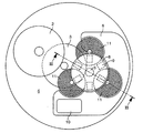
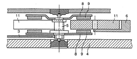
この従来技術による発電機の配置が、ここに添付する図1に示されており、この図1は部分的に組立てられた時計ムーブメントの平面図を示しており、また添付の図2に図1の横断面が示されている。この発電機は2つのフランジ8を備えたロータを含む。そのフランジは、ステータを構成しロータ軸に対して互いに120度づつオフセットしている3つの平坦なコイル11の両側にコイルの平面と平行な面に配置されている。
【0009】
6つの磁石9が放射状に、かつ一定の間隔で、各フランジ8のコイル11に向い合う面に固定されている。2つの平行または向い合っている磁石9は反対の極性を持つ。印刷回路6はプレート4に固定されており、コイル11を支持するために使用される。
【0010】
低消費電力の電気回路10は発電機によって動力を供給され、発電機はロータ5、フランジ8、磁石9およびコイル11からなるシャフト組立体によって構成され、連鎖接続3を介してバレル装置2により駆動される。したがって、バレル2に蓄えられた機械的動力がロータを駆動する。磁石9がコイル11の近くを通過することで、コイル11の端子に実質的に正弦波の誘導電圧を発生する。
【0011】
コイル11によって供給される電圧は実質的に正弦波である。制御装置の作動には整流電圧が必要である。電子制御回路10に電力を供給するために使用されるコイル11の端子間の電圧は、電気整流器回路を通って流れる。次いで、電圧は例えば整流器の出力電圧を4倍にするような増幅器段階を通過する。
【0012】
時計ムーブメントは一般にサイズが小さいので、製造や取り付けの不正確さが整流器回路の出力電圧の安定性に影響することは避けられない。増幅器段階では電圧変動を同じ大きさレベルで増幅する。したがって、全てのムーブメントに対して十分な整流電圧を1つの発電機から得るために、整流電圧の最小値を増大させて十分な誤差余裕が保たれる。
【0013】
整流電圧における誤差余裕が高ければ高いほど、通常の作動に必要な最小電圧が高くなり、このことは制御回路内の高い電力消費とバレル機構2の2回の巻上げ動作の間の時計の自律性を減少させるという結果をもたらす。
【0014】
【発明が解決しようとする課題】
本発明の目的はこの欠点を克服することである。
【0015】
【課題を解決するための手段】
それ故、本発明は、シャフトによって接続された2つのフランジと反対の極性を持つ2つの磁石が平行または向い合っている偶数の各フランジに固定された磁石とを含むロータを有する発電機を備えた時計ムーブメントに関する。この発電機はさらに、ロータの軸と平行な軸線を持つ1つまたは複数のコイルを含むステータを含んでおり、この1つまたは複数のコイルが磁石を備えた2つのフランジ間に挿入され、また基板によって支持されている。このムーブメントは、上記1つのコイルまたは上記複数コイルの少なくとも1つのコイルを含むステータの少なくとも一部に、上記ロータの軸と垂直な平面においてロータに対してその位置を調整できるように、コイルを移動させる手段が取り付けられ、ロータが回転する時に上記1つのコイルまたは上記複数コイルの少なくとも1つのコイルの端子間に誘導される電圧の振幅を調整できることを特徴とする。
【0016】
1つあるいは複数のコイルを支持する基板は、単一片またはいくつかの片のいずれででも形成することができ、また縦長または円弧状であって調整ガイドとして機能する長穴を設けることができる。
偏心当て具は1つのコイルまたは複数のコイルに生じる電圧調整を行い、また発電機が分解されるときにコイルの配置を記憶することができるという利点がある。
【0017】
【発明の実施の形態】
本発明の他の利点は、添付の概略図を参照してなされる限定的な意味ではない実施形態例の下記記述によって理解され明らかになるだろう。
その構造は従来技術で考察した、時計本体4、磁石9、フランジ8、電気回路10、ロータシャフト5およびステータコイル11a,11b,11cの要素を同一形態で再現している。
【0018】
下記の2つの実施形態は、ステータが少なくとも部分的に、コイル11a,11b,11cによって供給される電圧の調整ができるように、ロータに対して移動可能であるという同じ概念に基づいている。双方の実施形態とも、基板6にコイルが取り付けられており、少なくとも1つのコイルを支持している基板6の少なくとも一部は、時計本体4内で回転可能に支持されているロータに対して移動可能である。
【0019】
コイル11a,11bおよび/または11cのうちの少なくとも1つの相対的な位置が修正されると、これらのコイルにより供給される誘導電圧の振幅が修正される。それぞれの例において、3つの平らな円筒コイルを有するステータが使用される。基板6は印刷回路を含み、電気制御回路10を支持する。
【0020】
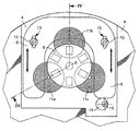
図3と図4に示されている第1の実施形態は3つのコイル11a,11bおよび11cを支持する単体基板6を含む。
2つの縦長の直線状の穴13が基板6に設けられる。穴13の長手方向の軸線は平行である。2つのねじ12が穴13を通り、時計本体4のねじ部にねじ込まれる。ステータの位置調整は、本体4と本体4の凹部26に配置された基板6間での相対的な動きができるように、ねじ12の締め付けを十分に緩めて行うことが可能である。
【0021】
変形形態においては、長手方向軸線に対して垂直な方向に沿って基板6の位置を僅かに調整できるように、穴13のレベルでねじ12の直径よりも大きい幅を持つ穴13を設けることが予見される。
【0022】
ねじ15で形成されている偏心軸の周りを回転するように取付けられ、基板に押し付けられている円筒ローラ14が、誘導された電圧の調整を制御し、かつその調整位置を記憶できるようにしている。本装置は電圧をオペレターが再調整する必要がないので、あらゆるメンテナンス作業に要求される分解作業の際のシステム組み立てを容易にする。
【0023】
好ましい変形形態においては、ローラ14はねじ15に固定されている。ねじ15は、好ましくは長穴13の長手方向軸線と直角方向で基板6の側面とローラ14と間で接触できるように、本体4に埋め込まれている。従って、ねじ15の回転はローラ14を駆動させ、ねじ15と基板6の間の距離が変化する。
【0024】
結果として、この当て具は、ステータの位置をねじ15を回転させることによって簡単に調整でき、動作位置は、ねじ15の新たな操作がないので変更されないまま記憶される。
【0025】
図5から図7に示されている第2の実施形態は2つのプレート61と62で形成された基板6を含み、そのうちの一つがコイル11aを支持し、もう一方がコイル11bと11cを支持する。この実施形態では、その調整は単にプレート61を軸の周りに回転させることによって行われる。プレート62は本体4に対して固定されたままである。
【0026】
縦長の湾曲した穴23はプレート61に形成され、穴23による円弧はねじ12aの軸に中心合わせされている。ねじ12aにプレート61を固定するために使用されるねじ22は穴23内に配置される。
【0027】
ねじ12aと12bによって固定されているブリッジ30は、一方がプレート61上にあり他方がプレート62上に設けられる2つの電気的ストリップ(図示せず)間の電気的接続を確立するのに使用される。ブリッジ30上のそれぞれのストリップ31と32は、ねじの通路となる穴33と34の周りに沿った円弧の形状の端部を持つ。その結果、接続はプレート61の位置が調整されプレート61が回転する時に確実に行われる。
【0028】
プレート62は2つのねじ12と12bで時計ムーブメントの本体4に固定される。ステータ位置の調整は、プレート61とコイル11aで形成される移動可能な半ステータのねじ12と12bの締付けを、半ステータを回転させることができるように十分に緩めて行うことができるできる。次いで、半ステータはねじ12aの周りに回転させられる。いったん調整されれば、ステータを本体4に固定するためにはねじ12と12aを締付ける必要があるのみである。
【0029】
第1の実施形態のように、ねじ15による偏心軸の周りに回転可能に取付けられ、基板61を押圧する円筒ローラ14が設けられる。この当て具は、移動可能な半ステータの位置をねじ15を回転させることによって簡単に調整することができる。
【0030】
第2の実施形態の変形形態においては、ステータ全体を円弧に沿って動かすようにすることができる。必要であれば、いくつかの縦長の湾曲した穴を設けることができる。
本発明は上記の実施形態に限定されるものではなく、特に均等の手段を用いる他の実施形態も考えられる。
【図面の簡単な説明】
【図1】従来技術による発電機の部分的に組立てられた時計ムーブメントの平面図である。
【図2】図1の時計ムーブメントの横断面図である。
【図3】単体の基板に固定された3つのコイルを含む、本発明による発電機を備えた時計ムーブメントの第1の実施形態の平面図である。
【図4】図3の時計ムーブメントの横断面図である。
【図5】コイルを支持するその一部が時計本体に対して旋回する調整部を持つ2つの部分からなる基板で形成される組立体を含む第2のの実施形態の平面図である。
【図6】図5の組立体の横断面図である。
【図7】第2の実施形態のブリッジ上の2つの基板部分の間の電気的接続配置を示す図である。
【符号の説明】
4 時計本体
5 ロータシャフト
6 基板
8 フランジ
9 磁石
11a,11b,11c コイル
12 ねじ
13 穴
14 円筒ローラ
15 ねじ[0001]
BACKGROUND OF THE INVENTION
The present invention particularly relates to a timepiece movement provided with a power generator for a wristwatch.
[0002]
[Prior art]
The use of batteries or accumulators is a factor that limits the shape of the device in all applications, especially in watches. In fact, changing or charging a battery or accumulator affects the usefulness and reliability of the watch.
[0003]
In this connection, the conventional mechanical timepiece has certain advantages in the watchmaking know-how, for example that the timepiece can be used permanently. Reloading of purely mechanical power is easily achieved by rewinding the watch mechanism.
[0004]
This type of timepiece uses a manual or automatic winding device that is commonly coupled to a control device commonly referred to as a “Swiss style lever escape”. It is difficult to obtain a high level of accuracy with this control device. This system is also relatively expensive.
[0005]
The other type, which occupies a lot, relates to regular quartz watches. A battery simultaneously powers the electric motor and the device that controls the operation of the motor. The rotation of the motor is driven / controlled by a nominal frequency given by quartz. This provides a high level of accuracy for time display. However, this device is relatively noisy because of the intermittent forward movement of the second wheel, and the batteries must be replaced periodically.
[0006]
A new type of watch combines the two systems described above and takes advantage of their respective advantages. In these structures, mechanical power storage is associated with quartz control and is powered by a generator driven by a mechanical part coupled to a power storage spring.
[0007]
The article “Self-winding mechanical movement with the accuracy of Salt-Quartz movement” by MM Born, Dinger and Farine described on pages 55 to 63 of “SSC study days 1997” issued by the Swiss Timing Association Can be cited as corresponding to
[0008]
This prior art generator arrangement is shown in FIG. 1 attached hereto, which shows a top view of a partially assembled watch movement, and FIG. The cross section of is shown. The generator includes a rotor with two
[0009]
Six
[0010]
The
[0011]
The voltage supplied by the
[0012]
Since the watch movement is generally small in size, it is inevitable that inaccuracies in manufacturing and installation will affect the stability of the output voltage of the rectifier circuit. In the amplifier stage, voltage fluctuations are amplified at the same magnitude level. Therefore, in order to obtain a sufficient rectified voltage from one generator for all the movements, the minimum value of the rectified voltage is increased to maintain a sufficient error margin.
[0013]
The higher the error margin in the rectified voltage, the higher the minimum voltage required for normal operation, which is the high power consumption in the control circuit and the clock autonomy between the two winding operations of the
[0014]
[Problems to be solved by the invention]
The object of the present invention is to overcome this drawback.
[0015]
[Means for Solving the Problems]
The invention therefore comprises a generator having a rotor comprising two flanges connected by a shaft and two magnets of opposite polarity fixed to each even number of flanges parallel or facing each other. Related to watch movement. The generator further includes a stator including one or more coils having an axis parallel to the axis of the rotor, the one or more coils being inserted between two flanges with magnets, and Supported by a substrate. The movement moves the coil to at least a part of the stator including at least one coil of the one coil or the plurality of coils so that its position can be adjusted with respect to the rotor in a plane perpendicular to the axis of the rotor. And a means for adjusting the amplitude of a voltage induced between terminals of at least one coil of the one coil or the plurality of coils when the rotor rotates.
[0016]
The substrate supporting one or more coils can be formed of either a single piece or several pieces, and can be provided with a slot that is vertically or arcuate and functions as an adjustment guide.
The eccentric applicator has the advantage that it can adjust the voltage produced in one coil or multiple coils and can memorize the arrangement of the coils when the generator is disassembled.
[0017]
DETAILED DESCRIPTION OF THE INVENTION
Other advantages of the present invention will be understood and apparent from the following description of example embodiments, which is not to be taken in a limiting sense, with reference to the accompanying schematic drawings.
The structure reproduces the elements of the
[0018]
The two embodiments described below are based on the same concept that the stator is movable relative to the rotor so that the voltage supplied by the
[0019]
When the relative position of at least one of the
[0020]
The first embodiment shown in FIGS. 3 and 4 includes a
Two vertically long
[0021]
In a variant, a
[0022]
A
[0023]
In a preferred variant, the
[0024]
As a result, this abutment can be easily adjusted by rotating the
[0025]
The second embodiment shown in FIGS. 5 to 7 includes a
[0026]
A vertically long
[0027]
The
[0028]
The
[0029]
As in the first embodiment, a
[0030]
In a variation of the second embodiment, the entire stator can be moved along an arc. If desired, several vertically curved holes can be provided.
The present invention is not limited to the above-described embodiment, and other embodiments using particularly equivalent means are also conceivable.
[Brief description of the drawings]
FIG. 1 is a plan view of a partially assembled watch movement of a generator according to the prior art.
2 is a cross-sectional view of the timepiece movement of FIG.
FIG. 3 is a plan view of a first embodiment of a timepiece movement with a generator according to the invention comprising three coils fixed to a single substrate.
4 is a cross-sectional view of the timepiece movement of FIG. 3;
FIG. 5 is a plan view of a second embodiment including an assembly formed of a two-part substrate, part of which supports the coil, with an adjustment part that pivots relative to the watch body.
6 is a cross-sectional view of the assembly of FIG.
FIG. 7 is a diagram showing an electrical connection arrangement between two substrate portions on a bridge according to a second embodiment.
[Explanation of symbols]
4 Watch body 5
Claims (7)
Applications Claiming Priority (2)
| Application Number | Priority Date | Filing Date | Title |
|---|---|---|---|
| EP99124389.0 | 1999-12-07 | ||
| EP99124389A EP1109083B1 (en) | 1999-12-07 | 1999-12-07 | Clockwork equipped with a generator |
Publications (2)
| Publication Number | Publication Date |
|---|---|
| JP2001208872A JP2001208872A (en) | 2001-08-03 |
| JP4444487B2 true JP4444487B2 (en) | 2010-03-31 |
Family
ID=8239550
Family Applications (1)
| Application Number | Title | Priority Date | Filing Date |
|---|---|---|---|
| JP2000369520A Expired - Fee Related JP4444487B2 (en) | 1999-12-07 | 2000-12-05 | Clock movement with generator |
Country Status (7)
| Country | Link |
|---|---|
| US (1) | US6381198B1 (en) |
| EP (1) | EP1109083B1 (en) |
| JP (1) | JP4444487B2 (en) |
| CN (1) | CN1149453C (en) |
| AT (1) | ATE429668T1 (en) |
| DE (1) | DE69940779D1 (en) |
| HK (1) | HK1039182B (en) |
Families Citing this family (10)
| Publication number | Priority date | Publication date | Assignee | Title |
|---|---|---|---|---|
| US20050256549A1 (en) * | 2002-10-09 | 2005-11-17 | Sirius Implantable Systems Ltd. | Micro-generator implant |
| US6826124B2 (en) | 2002-12-04 | 2004-11-30 | Asulab S.A. | Timepiece with power reserve indication |
| US7057977B1 (en) * | 2003-01-15 | 2006-06-06 | Timex Group B.V. | Flexible bridge for a watch module |
| JP5168843B2 (en) * | 2006-03-03 | 2013-03-27 | セイコーエプソン株式会社 | Chronograph clock |
| US20090171404A1 (en) * | 2006-03-17 | 2009-07-02 | Leland Standford Junior University | Energy generating systems for implanted medical devices |
| JP5205593B2 (en) * | 2006-08-14 | 2013-06-05 | 日産自動車株式会社 | Rotating electric machine |
| CH707787B1 (en) * | 2013-03-25 | 2021-09-15 | Richemont Int Sa | Regulating member for a wristwatch and method of assembling a regulating member for a wristwatch. |
| JP6506218B2 (en) * | 2016-07-15 | 2019-04-24 | セイコーインスツル株式会社 | Mechanism module, movement and watch |
| EP3964897B1 (en) | 2020-09-03 | 2024-07-03 | The Swatch Group Research and Development Ltd | Timepiece comprising a generator and method for mounting such a timepiece |
| CN114520579B (en) * | 2022-03-14 | 2023-10-03 | 中国计量大学 | Differential electromagnetic vibration energy harvester |
Family Cites Families (4)
| Publication number | Priority date | Publication date | Assignee | Title |
|---|---|---|---|---|
| US4795930A (en) * | 1987-12-03 | 1989-01-03 | Timex Corporation | Stepping motor coil core and stator assembly for a timepiece |
| US5059840A (en) * | 1991-01-25 | 1991-10-22 | Timex Corporation | Stator assembly for a timepiece stepping motor |
| EP0751445A1 (en) * | 1995-06-27 | 1997-01-02 | Asulab S.A. | Electric power generator for timepiece |
| US6097675A (en) * | 1997-09-26 | 2000-08-01 | Seiko Epson Corporation | Electronically controlled mechanical timepiece |
-
1999
- 1999-12-07 EP EP99124389A patent/EP1109083B1/en not_active Expired - Lifetime
- 1999-12-07 DE DE69940779T patent/DE69940779D1/en not_active Expired - Lifetime
- 1999-12-07 AT AT99124389T patent/ATE429668T1/en not_active IP Right Cessation
-
2000
- 2000-11-20 US US09/715,012 patent/US6381198B1/en not_active Expired - Lifetime
- 2000-12-05 JP JP2000369520A patent/JP4444487B2/en not_active Expired - Fee Related
- 2000-12-07 CN CNB001350366A patent/CN1149453C/en not_active Expired - Fee Related
-
2002
- 2002-01-14 HK HK02100261.0A patent/HK1039182B/en not_active IP Right Cessation
Also Published As
| Publication number | Publication date |
|---|---|
| EP1109083A1 (en) | 2001-06-20 |
| US6381198B1 (en) | 2002-04-30 |
| JP2001208872A (en) | 2001-08-03 |
| HK1039182A1 (en) | 2002-04-12 |
| DE69940779D1 (en) | 2009-06-04 |
| CN1305127A (en) | 2001-07-25 |
| CN1149453C (en) | 2004-05-12 |
| ATE429668T1 (en) | 2009-05-15 |
| EP1109083B1 (en) | 2009-04-22 |
| HK1039182B (en) | 2005-03-04 |
Similar Documents
| Publication | Publication Date | Title |
|---|---|---|
| JP4444487B2 (en) | Clock movement with generator | |
| EP1662343B1 (en) | Electronic apparatus, method for detecting positions of pointer members in electronic apparatus, and a program for detecting positions of pointer members in electronic apparatus | |
| US4126796A (en) | Miniature reversible motor | |
| JP2001186731A (en) | Generator for clocking | |
| EP0905587B1 (en) | Electronically controlled mechanical timepiece | |
| WO2001035171A1 (en) | Mechanical timepiece with timed annular balance rotating angle control mechanism | |
| US7031230B1 (en) | Starter for electricmagnetic converter, and timepiece | |
| US6469959B1 (en) | Generator in particular for a timepiece | |
| US6431746B1 (en) | Mechanical timepiece with timed annular balance rotating angle control mechanism | |
| JPH09211152A (en) | Generator for time piece | |
| JP7463744B2 (en) | clock | |
| US3570238A (en) | Direct current electric timepiece | |
| JPS593754A (en) | Magnetic disk device | |
| JPS593753A (en) | Magnetic disk device | |
| JP3674444B2 (en) | Small generator and electronic device equipped with the same | |
| CN114137816B (en) | Timepiece comprising a generator and method for assembling such a generator | |
| US3808792A (en) | Drive mechanism of an electric timepiece | |
| WO2001035172A1 (en) | Mechanical timepiece with timed annular balance rotating angle control mechanism including coils | |
| JP2556929Y2 (en) | PG coil position adjustment mechanism | |
| JPH0739320Y2 (en) | Flat motor | |
| JP3038823B2 (en) | clock | |
| JP4670396B2 (en) | clock | |
| JP2003279670A (en) | Timepiece | |
| JP2003066167A (en) | Electromagnetic generator and electronic apparatus equipped therewith | |
| JPS593762A (en) | Magnetic disk device |
Legal Events
| Date | Code | Title | Description |
|---|---|---|---|
| A621 | Written request for application examination |
Free format text: JAPANESE INTERMEDIATE CODE: A621 Effective date: 20070907 |
|
| TRDD | Decision of grant or rejection written | ||
| A01 | Written decision to grant a patent or to grant a registration (utility model) |
Free format text: JAPANESE INTERMEDIATE CODE: A01 Effective date: 20091215 |
|
| A01 | Written decision to grant a patent or to grant a registration (utility model) |
Free format text: JAPANESE INTERMEDIATE CODE: A01 |
|
| A61 | First payment of annual fees (during grant procedure) |
Free format text: JAPANESE INTERMEDIATE CODE: A61 Effective date: 20100114 |
|
| R150 | Certificate of patent or registration of utility model |
Free format text: JAPANESE INTERMEDIATE CODE: R150 |
|
| FPAY | Renewal fee payment (event date is renewal date of database) |
Free format text: PAYMENT UNTIL: 20130122 Year of fee payment: 3 |
|
| R250 | Receipt of annual fees |
Free format text: JAPANESE INTERMEDIATE CODE: R250 |
|
| R250 | Receipt of annual fees |
Free format text: JAPANESE INTERMEDIATE CODE: R250 |
|
| R250 | Receipt of annual fees |
Free format text: JAPANESE INTERMEDIATE CODE: R250 |
|
| R250 | Receipt of annual fees |
Free format text: JAPANESE INTERMEDIATE CODE: R250 |
|
| LAPS | Cancellation because of no payment of annual fees |


