JP5168843B2 - Chronograph clock - Google Patents
Chronograph clock Download PDFInfo
- Publication number
- JP5168843B2 JP5168843B2 JP2006212913A JP2006212913A JP5168843B2 JP 5168843 B2 JP5168843 B2 JP 5168843B2 JP 2006212913 A JP2006212913 A JP 2006212913A JP 2006212913 A JP2006212913 A JP 2006212913A JP 5168843 B2 JP5168843 B2 JP 5168843B2
- Authority
- JP
- Japan
- Prior art keywords
- minute
- lever
- hammer
- nulling
- wheel
- Prior art date
- Legal status (The legal status is an assumption and is not a legal conclusion. Google has not performed a legal analysis and makes no representation as to the accuracy of the status listed.)
- Active
Links
- 230000007246 mechanism Effects 0.000 claims description 50
- 230000009471 action Effects 0.000 claims description 12
- 230000001105 regulatory effect Effects 0.000 claims description 7
- 230000005540 biological transmission Effects 0.000 description 44
- 210000000078 claw Anatomy 0.000 description 24
- 229910021385 hard carbon Inorganic materials 0.000 description 12
- 230000001276 controlling effect Effects 0.000 description 8
- 238000000034 method Methods 0.000 description 7
- 238000005259 measurement Methods 0.000 description 6
- 238000003825 pressing Methods 0.000 description 6
- 238000004519 manufacturing process Methods 0.000 description 5
- 230000009191 jumping Effects 0.000 description 4
- 238000005268 plasma chemical vapour deposition Methods 0.000 description 3
- 238000005299 abrasion Methods 0.000 description 2
- 239000011248 coating agent Substances 0.000 description 2
- 238000000576 coating method Methods 0.000 description 2
- 230000008569 process Effects 0.000 description 2
- OKTJSMMVPCPJKN-UHFFFAOYSA-N Carbon Chemical compound [C] OKTJSMMVPCPJKN-UHFFFAOYSA-N 0.000 description 1
- 230000015572 biosynthetic process Effects 0.000 description 1
- 229910052799 carbon Inorganic materials 0.000 description 1
- 238000010586 diagram Methods 0.000 description 1
- 238000011156 evaluation Methods 0.000 description 1
- 238000010030 laminating Methods 0.000 description 1
- 238000012986 modification Methods 0.000 description 1
- 230000004048 modification Effects 0.000 description 1
- 230000002093 peripheral effect Effects 0.000 description 1
- 239000010453 quartz Substances 0.000 description 1
- VYPSYNLAJGMNEJ-UHFFFAOYSA-N silicon dioxide Inorganic materials O=[Si]=O VYPSYNLAJGMNEJ-UHFFFAOYSA-N 0.000 description 1
- 238000004804 winding Methods 0.000 description 1
Images


Classifications
-
- G—PHYSICS
- G04—HOROLOGY
- G04F—TIME-INTERVAL MEASURING
- G04F8/00—Apparatus for measuring unknown time intervals by electromechanical means
- G04F8/006—Apparatus for measuring unknown time intervals by electromechanical means running only during the time interval to be measured, e.g. stop-watch
-
- G—PHYSICS
- G04—HOROLOGY
- G04F—TIME-INTERVAL MEASURING
- G04F7/00—Apparatus for measuring unknown time intervals by non-electric means
- G04F7/04—Apparatus for measuring unknown time intervals by non-electric means using a mechanical oscillator
- G04F7/08—Watches or clocks with stop devices, e.g. chronograph
- G04F7/0804—Watches or clocks with stop devices, e.g. chronograph with reset mechanisms
Description
本発明は、クロノグラフ時計に関する。詳しくは、複数の経過時間表示部の帰零構造に関する。 The present invention relates to a chronograph timepiece. Specifically, the present invention relates to a zero return structure of a plurality of elapsed time display units.
従来、通常の時刻表示部と経過時間を表示する経過時間表示部(クロノグラフ表示部と表すことがある)とを有するクロノグラフ時計において、経過時間表示部が1/10秒単位、1秒単位、1分単位、1時間単位の4つの表示部からなり、これら4つの表示部を帰零するために、それぞれの表示部を帰零する4つの帰零レバーを備えているクロノグラフ時計というものが知られている(例えば、特許文献1参照)。 Conventionally, in a chronograph timepiece having a normal time display section and an elapsed time display section (sometimes referred to as a chronograph display section) for displaying elapsed time, the elapsed time display section is in units of 1/10 second and 1 second. A chronograph watch that consists of four display units in units of one minute and one hour, and has four nulling levers that null each display unit in order to null these four display units Is known (see, for example, Patent Document 1).
このような特許文献1では、上述した各表示部それぞれに対応する帰零レバーを備えているために、各表示部の位置ばらつき、帰零レバーの寸法等のばらつきの影響を受けにくいため、それぞれの表示部の帰零を正確に行うことができる。
In such a
しかしながら、各表示部に対応する帰零レバーを備えていること、これらの帰零レバーを単独に作動させるためにばね部材等を備えていることから、構成する部品数が増加し、構造が複雑になるという課題を有している。 However, since it has a zero return lever corresponding to each display unit and a spring member etc. for operating these zero return levers independently, the number of components increases and the structure is complicated. Has the problem of becoming.
また、各表示部の位置ばらつき、帰零レバーの寸法等のばらつきの影響をさらに少なくするために、帰零レバーの形状の水準を複数種類用意しておき、その水準の中から適宜選択して組立てることも考えられるが、組立時に水準の選択評価をする必要があることから、生産効率が低下することが予測される。 In addition, in order to further reduce the influence of variations in the position of each display, variation in the size of the nulling lever, etc., a plurality of types of shape of the nulling lever are prepared, and an appropriate selection can be made from these levels. Assembling is also conceivable, but it is predicted that the production efficiency will be lowered because it is necessary to carry out selective evaluation of the level at the time of assembling.
本発明の目的は、前述した課題を解決することを要旨とし、複数の経過時間表示部の正確な帰零を可能にし、部品数を低減して構造を簡素化すると共に生産効率を高めることができるクロノグラフ時計を提供することである。 The object of the present invention is to solve the above-mentioned problems, and to enable accurate nulling of a plurality of elapsed time display units, to reduce the number of parts, simplify the structure, and increase production efficiency. It is to provide a chronograph watch that can.
本発明のクロノグラフ時計は、平面方向に離間した複数の経過時間表示部を有するムーブメントを備えるクロノグラフ時計であって、前記複数の経過時間表示部をほぼ同時に機械的に帰零させる一つの帰零部材を備え、前記帰零部材が、前記複数の時間表示部それぞれを帰零する帰零作動部を有していることを特徴とする。
ここで、経過時間表示部は、例えば、クロノグラフ時計において秒単位、分単位、時間単位等の時間計測結果を表示するクロノグラフ表示部を意味する。
A chronograph timepiece according to the present invention is a chronograph timepiece having a movement having a plurality of elapsed time display portions spaced apart in a plane direction, wherein the plurality of elapsed time display portions are mechanically nulled substantially simultaneously. A zero member is provided, and the nulling member has a nulling operation unit that nullifies each of the plurality of time display units.
Here, the elapsed time display unit means, for example, a chronograph display unit that displays time measurement results such as seconds, minutes, and hours in a chronograph timepiece.
この発明によれば、複数備えられる経過時間表示部を1体で構成される帰零部材によって帰零する構造であるため、前述した従来技術による構造にくらべ、部品数を格段に低減することができる。また、帰零部材を作動する部品も低減できることから構造を簡素化することができ、コストの大幅な低減を実現できる。 According to the present invention, a plurality of elapsed time display sections are structured to be returned by a return member constituted by a single body, so that the number of parts can be significantly reduced compared to the structure according to the prior art described above. it can. In addition, since the number of components that operate the zero return member can be reduced, the structure can be simplified, and the cost can be significantly reduced.
また、前記帰零作動部のうちの少なくとも一つが、対応する経過時間表示部に対する位置を調整する調整機構を備えていることが好ましい。 Further, it is preferable that at least one of the zero return operation units includes an adjustment mechanism for adjusting a position with respect to a corresponding elapsed time display unit.
仮に、経過時間表示部が秒単位、分単位、時間単位等の時間計測結果を表示する3つのクロノグラフ表示部を有し、一つの帰零部材で帰零する場合、帰零部材はクロノグラフ表示部それぞれを帰零する3つの帰零作動部を備えることになる。しかしながら、3つのクロノグラフ表示部及び3つの帰零作動部それぞれの寸法の製造上のばらつきから、3つの表示部の帰零が完全にできないことが考えられる。 If the elapsed time display unit has three chronograph display units for displaying time measurement results such as seconds, minutes, hours, etc., and a nulling member returns, the nulling member is a chronograph. Three nulling operation units for nulling each display unit are provided. However, it is conceivable that the nulling of the three display units cannot be completed completely due to manufacturing variations in the dimensions of the three chronograph display units and the three nulling operation units.
ここで、帰零作動部の少なくとも一つに、その位置を調整する調整機構を設けることにより、他の帰零作動部とクロノグラフ表示部とのそれぞれの位置関係に対応して調整することにより、複数の表示部の帰零を同時に正確に行うことができる。 Here, by providing an adjustment mechanism for adjusting the position of at least one of the zero return operation units, the adjustment is performed according to the positional relationship between the other zero return operation units and the chronograph display unit. In addition, it is possible to accurately perform nulling of a plurality of display units simultaneously.
また、前記帰零部材が、前記調整機構によって位置調整可能な帰零作動部を有する可動レバーと、他の帰零作動部を有する帰零部材体とを備え、前記帰零部材体と前記可動レバーとが可動レバー固定ねじによって固定され、前記調整機構が、前記他の帰零作動部に対する前記可動レバーの位置調整を行う偏心軸を備えていることが好ましい。 In addition, the nulling member includes a movable lever having a nulling action portion whose position can be adjusted by the adjusting mechanism, and a nulling member body having another nulling action portion, and the nulling member body and the movable member are provided. It is preferable that the lever is fixed by a movable lever fixing screw, and the adjustment mechanism includes an eccentric shaft for adjusting the position of the movable lever with respect to the other nulling operation unit.
このようにすれば、可動レバー固定ねじを緩めて可動レバーの位置調整をし、前記可動レバー固定ねじを締めて可動レバーと帰零部材体との一体化を容易に行うことができる。
また、偏心軸を回転することで可動レバーの位置調整を行うので、位置の微調整を容易に行うことができる。
In this way, the movable lever fixing screw can be loosened to adjust the position of the movable lever, and the movable lever fixing screw can be tightened to easily integrate the movable lever and the zero return member.
Further, since the position of the movable lever is adjusted by rotating the eccentric shaft, the position can be easily finely adjusted.
また、前記帰零部材には、前記帰零部材体と前記可動レバーとの間に弾性部材がさらに備えられ、前記可動レバー固定ねじを緩めたとき、前記可動レバーの前記帰零部材に対する平面方向位置が、前記弾性部材の弾性力によって保持されていることが好ましい。 Further, the nulling member is further provided with an elastic member between the nulling member body and the movable lever, and when the movable lever fixing screw is loosened, a planar direction of the movable lever with respect to the nulling member It is preferable that the position is held by the elastic force of the elastic member.
可動レバーの位置調整を行うため固定ねじを緩めると、可動レバーが移動自在になり、位置が定まらないということが考えられる。従って、帰零部材体と前記可動レバーとの間に弾性部材を設けることにより、可動レバーが弾性部材の弾性力によって、位置調整後、可動レバー固定ねじを締めて、再度固定するまでその位置が保持されるため、所望の位置に正確に調整することができる。 If the fixing screw is loosened to adjust the position of the movable lever, the movable lever becomes movable and the position cannot be determined. Therefore, by providing an elastic member between the nulling member and the movable lever, the position of the movable lever is adjusted until the movable lever is fixed again by tightening the movable lever fixing screw after adjusting the position by the elastic force of the elastic member. Since it is held, it can be accurately adjusted to a desired position.
また、本発明では、前記帰零部材の移動方向に沿って両側方向外側に配設される二つの帰零作動部を基準とし、前記調整機構が、前記二つの帰零作動部の間に配設される前記可動レバーに前記調整機構が備えられていることが好ましい。 Further, in the present invention, with reference to two nulling action parts arranged on both sides in the moving direction of the nulling member, the adjusting mechanism is arranged between the two nulling action parts. It is preferable that the movable lever provided is provided with the adjusting mechanism.
このようにすれば、上述した帰零部材体に設けられる二つの帰零作動部に挟まれた位置にある可動レバーに調整機構を備えているため、調整機構による調整幅を小さくすることができ、調整機構そのものを小型化することができる。 In this way, since the adjustment mechanism is provided in the movable lever located between the two zero return operation portions provided in the above-described zero return member body, the adjustment range by the adjustment mechanism can be reduced. The adjustment mechanism itself can be reduced in size.
さらに、前記調整機構と、前記可動レバーに設けられる帰零作動部に対応する経過時間表示部の一部とが、前記ムーブメントの一方の表面方向から覗けるよう配設されていることが望ましい。 Further, it is desirable that the adjustment mechanism and a part of an elapsed time display unit corresponding to the zero return operation unit provided in the movable lever are arranged so as to be viewed from one surface direction of the movement.
従って、帰零作動部の位置調整を帰零部材単体で調整することや、またはムーブメント組立途中で行うことも可能であるが、このような場合、姿勢が安定せず調整作業がやりにくいことが考えられる。また、他の構成部品との寸法関係から、ムーブメント完成時に調整が不十分であったというようなことが予測される。しかし、ムーブメントの組立て最終工程において調整することにより、姿勢が安定し調整作業が容易になると共に、他の構成部品の影響を含めた調整を行うことができる。 Therefore, it is possible to adjust the position of the return zero operating part by itself, or during the movement assembly, but in such a case, the posture is not stable and adjustment work is difficult. Conceivable. In addition, from the dimensional relationship with other components, it is predicted that the adjustment was insufficient when the movement was completed. However, by adjusting in the final assembly step of the movement, the posture is stabilized and the adjustment work becomes easy, and the adjustment including the influence of other components can be performed.
以下、本発明の実施の形態を図面に基づいて説明する。
図1〜図7は本発明の実施の形態に係るクロノグラフ時計を示し、図8は帰零部材としての復針レバーの調整方法を示している。
(実施形態)
Hereinafter, embodiments of the present invention will be described with reference to the drawings.
1 to 7 show a chronograph timepiece according to an embodiment of the present invention, and FIG. 8 shows a method for adjusting a hammer as a zero return member.
(Embodiment)
図1は、本発明の実施形態に係るクロノグラフ時計のムーブメントの一部を示す平面図である。本発明は、クロノグラフ時計の経過時間表示部としての複数のクロノグラフ表示部を同時に機械的に帰零動作する構造に特徴を有しているため、特徴を有するクロノグラフ機構を中心に説明する。 FIG. 1 is a plan view showing a part of a movement of a chronograph timepiece according to an embodiment of the present invention. The present invention is characterized by a structure in which a plurality of chronograph display units as an elapsed time display unit of a chronograph timepiece are mechanically nulled simultaneously. Therefore, the chronograph mechanism having the features will be mainly described. .
また、本発明の帰零構造は、機械式時計、電子制御式機械時計、アナログ式クォーツ時計等のいずれにも採用可能であるが、本実施の形態では、自動巻機械式時計を例示して説明する。 Further, the nulling structure of the present invention can be adopted in any of a mechanical timepiece, an electronically controlled mechanical timepiece, an analog type quartz timepiece, etc., but in this embodiment, an automatic winding mechanical timepiece is exemplified. explain.
また、クロノグラフ表示部としては、時クロノグラフ表示部(以降、時CG表示部と表す)、分クロノグラフ表示部(以降、分CG表示部と表す)、秒クロノグラフ表示部(以降、秒CG表示部と表す)の3つを備える構造を例示して説明する。 The chronograph display section includes an hour chronograph display section (hereinafter referred to as hour CG display section), a minute chronograph display section (hereinafter referred to as minute CG display section), and a second chronograph display section (hereinafter referred to as seconds). An example of a structure including three of the CG display units will be described.
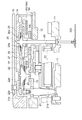
図1は、本実施形態に係るクロノグラフ時計1におけるムーブメント10のクロノグラフ機構を示す平面図、図2は、時CG表示部の構造を示す部分断面図、図3は、秒CG表示部及び分CG表示部の構造を示す部分断面図である。図1は、クロノグラフ計測のスタート状態を示している。
FIG. 1 is a plan view showing a chronograph mechanism of a
本実施形態のクロノグラフ機構は、基本構成としてクロノグラフのスタート、ストップ、帰零の状態を制御する作動カム機構と、スタート、ストップ動作を制御する作動機構と、帰零動作を制御する帰零機構と、クロノグラフ表示機構の4つの機構から構成されている。 The chronograph mechanism of the present embodiment includes, as a basic configuration, an operating cam mechanism that controls the start, stop, and zero return states of the chronograph, an operation mechanism that controls the start and stop actions, and a zero return that controls the return zero action. It consists of four mechanisms: a mechanism and a chronograph display mechanism.
作動カム機構は、作動カム70と、作動カム70の回転位置を規制する作動カムジャンパー120と、作動レバー80と、作動レバーばね90とから構成されている。作動カム70は、外周に歯部71と歯部71の内側に設けられる複数の柱部72とから構成されており、隣接する柱部72の間には空隙部73が形成されている。
The operating cam mechanism includes an
作動カム70は、輪列受12(図2,3、参照)に植立された回転案内軸74に、作動カム固定ねじ75によって回転可能に固定されている。この作動カム70は、作動カムジャンパー120によって、回転方向の位置が規制されている。
The
作動カムジャンパー120は、本体部から延在されたばね部122と、ばね部122の先端に形成される作動カム規制部121とから形成され、固定ねじ123によって輪列受12に固定されている。
The
また、作動カムジャンパー120は、作動カム規制部121を歯部71に押し圧することで、作動カム70の回転位置を規制している。作動カム70の柱部72の数は、歯部71の数の1/2に設定されており、作動レバー80を一度作動する度に歯部71を1ピッチずつ時計回り方向に回転し、柱部72を半ピッチ移動して柱部72の位置を帰零状態とスタート、ストップの状態に交互に移動させる。
Further, the
作動レバー80は、端部にボタン2によって押動される押し部84と、押し部84の反対側端部に作動カム70を作動させる爪部83と、中央部に作動案内孔85と、が形成され、表面方向に作動レバーばね掛け軸82が植立されている。作動案内孔85は、輪列受12に植立された作動レバー軸81に挿着され、作動レバー80は作動案内孔85の範囲で移動する。作動レバー80は、作動レバー軸81において、固定ねじ86によって移動可能に固定されている。
なお、作動レバー80は、ボタン2の操作を止めたとき、作動レバーばね90によって、初期位置(何も操作しない状態、図中二点鎖線にて表す)に復帰させる。
The actuating
When the operation of the
作動レバーばね90は、固定部91と、固定部91から延在されたばね部92と、ばね部92の先端部に設けられる作動レバー係合部93とから構成され、固定ねじ94によって輪列受12に固定されている。
The operating
作動レバー係合部93は、作動レバー80に植立された作動レバーばね掛け軸82に係合し、作動レバー80を外側方向(初期位置方向)に押し圧している。従って、作動レバー80は、ボタン操作によって作動レバーばね90が撓んで作動カム70を作動し、ボタン2を離すと作動レバーばね90の弾性力によって初期位置に戻される。
The operating
続いて、本実施形態の帰零機構について説明する。帰零機構は、ボタン3の押し操作によって作動する復針伝達レバー130と、復針伝達レバー130上面に揺動可能に取り付けられる復針伝えレバ−140と、復針伝達レバー130を初期状態に戻すための復針伝達レバーばね200と、クロノグラフ表示部を帰零する復針レバー160と、復針レバー160を作動制御する復針制御レバー150と、帰零部材としての復針制御レバー150の位置を規制する復針ジャンパー180とを備えて構成されている。
Next, the nulling mechanism of this embodiment will be described. The zero-return mechanism returns the
復針伝達レバー130は、端部にボタン3によって押動される押し部134と、この押し部134の反対側端部に形成される復針伝達レバーばね係合部132を備えて形成されている。復針伝達レバー130の上面には、復針伝えレバ−140が揺動可能に復針伝えレバー軸133によって軸止されている。
The
また、復針伝達レバー130は、復針伝えレバ−140が取り付けられた状態で、輪列受12に復針伝達レバー軸131によって揺動可能に軸止されている。なお、復針伝達レバー130は、復針伝達レバーばね係合部132を復針伝達レバーばね200によって押し圧することで、時計回り方向に回転力が与えられ、ボタン操作がないときには図1に示している初期位置にある。
The
復針伝えレバ−140は、両端部に作動カム係合部141と復針制御レバー係合部142とを備え、略中央部を復針伝えレバ−軸133によって揺動可能に軸止されている。図1に示すスタートの状態では、復針伝えレバー140の作動カム係合部141は、作動カム70の空隙部73bの位置にある。従って、復針伝えレバ−140は位置が規制されていない状態のため、復針伝達レバー130を作動しても後段の復針制御レバー150を押し圧しない。
The
復針制御レバー150は、3方向に半島状の突出部を有し、一つが、作動カム70の柱部72と係合する作動カム係合部152、他の一つが復針ジャンパー180と係合する復針ジャンパー係合部153、もう一つの突出部には、復針レバー160を作動するための復針レバー作動軸154が植立されている。
The
このように構成される復針制御レバー150は、輪列受12に植立される復針制御レバー軸151に挿着され、固定ねじ155によって揺動可能に軸止されている。そして、復針ジャンパー180の規制部182bに復針制御レバー150の復針ジャンパー係合部153が係合することによって復針制御レバー150の位置が規制される。作動カム係合部152と作動カム70の柱部72との間には、わずかな隙間が存在する。
The
復針ジャンパー180は、本体部183と、本体部183から延在されるばね部181と、ばね部181の先端部に設けられる復針制御レバー規制部182とを備え、輪列受12に固定ねじ184によって固定されている。復針制御レバー規制部182には、二つの窪みからなる規制部182a、182bが設けられ、この規制部182bから規制部182aに復針制御レバー150の復針ジャンパー係合部153が移動する際に、規制部182a、182bの間の凸部を乗り越えることで、帰零操作に節度ある動きと感触を与える。
The
復針制御レバー150の端部に植立された復針レバー作動軸154は、復針レバー160に設けられた復針レバー作動孔166に挿入され、復針伝達レバー130の作動によって、復針レバー160を作動する。しかし、図1の状態では、復針伝達レバー130の動きは、復針伝えレバー140の作動力としては伝達されず、復針レバー160は作動しない。また、復針制御レバー150の作動カム係合部152が、作動カム70の柱部72に当接し、復針制御レバー150がそれ以上に作動することはない。
The
帰零部材としての復針レバー160は、帰零部材体としての復針レバー体161と、可動レバーとしての分復針レバー170とが固定されて構成されている。復針レバー体161は、復針レバー160の作動方向に沿って両側に略Y字状に延在された時CG車作動部164と秒CG車作動部165とを備えている。さらに、作動案内孔163,161aと復針レバー作動孔166とが設けられている。
The hammer 122 as a return member is configured by fixing a
復針レバー体161には、調整軸としての偏心軸167と分復針レバー案内軸168と分復針レバー固定軸174とが植立されている。これら偏心軸167と分復針レバー案内軸168と分復針レバー固定軸174それぞれに、分復針レバー170に設けられている調整孔171、分復針レバー固定軸孔175、分復針レバー案内孔173を挿着して、分復針レバー固定ねじ176にて復針レバー体161と分復針レバー170とを一体化する。
なお、復針レバー160の構造については、後述する図5,6を参照して詳しく説明する。
An
The structure of the
上述したように復針レバー体161と分復針レバー170とが一体化された復針レバー160は、輪列受12に植立された復針レバー案内軸162,158それぞれに作動案内孔163,161aを挿着し、復針レバー案内軸162において復針レバー160が作動案内孔163,161aに沿って作動可能に復針レバー固定ねじ177によって固定される。
As described above, the
クロノグラフ表示部がスタート状態のときには、復針レバー160の時CG車作動部164、分CG車作動部172、秒CG車作動部165は、それぞれ時ハートカム28、分ハートカム63、秒ハートカム41とは離間している。すなわち、時CG車25、分CG車60、秒CG車40は駆動している。
When the chronograph display portion is in the start state, the hour CG
次に、前述した作動カム機構と、この作動機構に連動して、クロノグラフ表示部の作動,停止を司る機構について図1を参照して説明する。スタートの状態において、作動カム70は図1に示す状態であって、第一発停レバー100の作動カム係合部103は、作動カム70の空隙部73aに入り込んでいる。
Next, the operation cam mechanism described above and a mechanism for controlling the operation and stop of the chronograph display unit in conjunction with the operation mechanism will be described with reference to FIG. In the start state, the operating
第一発停レバー100は、3方向に半島状に突出した作動カム係合部103とクラッチ作動部101と第二発停レバー係合部104とが形成されている。そして、第一発停レバー軸102に軸支され、固定ねじ105によって揺動可能に輪列受12に固定されている。この第一発停レバー100は、第二発停レバー110によって、作動カム70の方向に押し圧されている。
The first start /
なお、第一発停レバー100の表面には硬質炭素膜処理(例えば、DLC処理/ダイヤモンドライクカーボン)が施されている。硬質炭素膜処理は、第一発停レバー100の少なくともクラッチ作動部101、クラッチ係合部105(図3、参照)、作動カム係合部103、第二発停レバー係合部104にイオンプレーティング、プラズマCVD等の成膜手段により形成されている。
A hard carbon film treatment (for example, DLC treatment / diamond-like carbon) is applied to the surface of the first start /
硬質炭素膜処理の厚さは第一発停レバー100の部位に応じて変化させることが好ましい。詳しくは、クラッチ作動部101やクラッチ係合部105及び表裏平面部は1μm、作動カム係合部103と第二発停レバー係合部104及び他の断面部には0.5μmの厚さとする。これは、第一発停レバー100の特に摺動性、耐久性(耐磨耗性)が要求される部位に対しては十分な膜厚と膜密着力を得るためである。また、第一発停レバー100の表裏両面の厚さは、硬質炭素膜の膜応力による反りを防止するために好適な厚さとしている。
The thickness of the hard carbon film treatment is preferably changed according to the position of the first start /
硬質炭素膜処理としてプラズマCVD法を用いる場合には、プラズマに対向する面と、直交する面における膜厚の比は2:1となる。従って、第一発停レバー100の広い平面部を有する面をプラズマに対向するように配設して膜形成すれば所望の厚さを得ることができる。
When the plasma CVD method is used as the hard carbon film treatment, the ratio of the film thickness between the surface facing the plasma and the surface orthogonal to the plasma is 2: 1. Therefore, a desired thickness can be obtained by forming a film by disposing the surface of the first start /
第二発停レバー110は、第一発停レバー100の第二発停レバー係合部104と係合する第一発停レバー係合部113と、クラッチ作動部111とばね部114とを有している。また、第二発停レバー110は、第二発停レバー軸112に軸支され、第二発停レバー固定ねじ118によって揺動可能に輪列受12に固定され、クラッチ作動部111の根元部を第二発停レバー押え軸116の鍔により浮き上がることを防止している。
The second start /
なお、第二発停レバー110の表面にも硬質炭素膜処理が施されている。硬質炭素膜処理は、第二発停レバー110の少なくともクラッチ作動部111、クラッチ係合部118、第一発停レバー係合部113、ばね部114のばね掛け軸115との係合部にイオンプレーティング、プラズマCVD等の成膜手段により形成されている。
A hard carbon film treatment is also applied to the surface of the second start /
第二発停レバー110における硬質炭素膜の形成方法や厚さも第一発停レバー100と同様に部位によって変化させている。クラッチ作動部111やクラッチ係合部118及び表裏平面部は1μm、第一発停レバー係合部113、他の断面部には0.5μmの厚さとする。これは、第二発停レバー110の特に摺動性、耐久性(耐磨耗性)が要求される部位に対しては十分な膜厚と膜密着力を得るためである。また、第二発停レバー110の表裏両面の厚さは、硬質炭素膜の膜応力による反りを防止するために好適な厚さとしている。
The formation method and thickness of the hard carbon film in the second start /
第二発停レバー110は、ばね部114が、輪列受12に植立されたばね掛け軸115に係合され、半時計回り方向に回転力が付与され、第一発停レバー係合部113によって第一発停レバー100を時計回り方向に回転力を付勢している。スタート状態では、前述したように第一発停レバー100の作動カム係合部103が作動カム70の空隙部73aに入りこんでいるため、第一発停レバー100のクラッチ作動部101と、第二発停レバー110のクラッチ作動部111とは、秒CG車40に挿着されているクラッチ44(図3も参照する)とは離間し、秒CG車40の駆動を妨げない。そして、第二発停レバー110に連動して時CG規正レバー190が作動される。
In the second start /
時CG規正レバー190は、ばね部192と時CG車規正部193とを有し、時CG規正レバー軸191に揺動可能に軸支され、規正レバー固定ねじ195によって輪列受12に固定されている。
The hour
また、時CG規正レバー190は、ばね部192の先端部が第二発停レバー110に設けられる時CG規正レバーばね掛け部117に係合し、第二発停レバー110の作動に連動する。スタート状態において、時CG規正レバー190は、第二発停レバー110によって時CG規正レバー軸191を中心に時計回り方向に回転されている。従って、時CG車規正部193が時CG車25と離間し、時CG車25の駆動を妨げない。
The hour
続いて、クロノグラフ表示機構としての時CG車25、分CG車60、秒CG車40の構造について説明する。
まず、駆動源としての香箱20から後段の時CG車25までの時CG輪列について、図1、図2を参照して説明する。
図2は、時CG輪列の構造を示す断面図である。図1、図2において、時CG輪列は、香箱20の回転を伝達する第一時CG中間車21、第二時CG中間車22、時CG車25とから構成されている。
Next, the structure of the
First, the hour CG wheel train from the
FIG. 2 is a cross-sectional view showing the structure of the hour CG train wheel. 1 and 2, the hour CG wheel train is composed of a first temporary CG
第一時CG中間車21は、地板11と輪列受12によって軸支されており、第一時CG中間車真21aに設けられる歯車が香箱20の歯車と噛合している。第一時CG中間車真21aは、輪列受12の上方に突出され、先端部に小歯車21bが軸止されている。この小歯車21bに第二時CG中間車22が噛合している。
The first temporary CG
第二時CG中間車22は、第二時CG中間かな22aと第二時CG中間歯車22bとから構成され、輪列受12と回転錘受14によって軸支されている。この第二時CG中間歯車22bに時CG車25が噛合している。
The second hour CG
時CG車25は、時CG車真26と、時CG歯車27と、スリップばね29と、時ハートカム28とから構成され、地板11と回転錘受14との間で軸支されている。詳しくは、時CG車真26に設けられる鍔部26aを挟んで下方側に時ハートカム28、上方側に時CG歯車27が軸支されている。そして、時CG歯車27の上方にスリップばね29が挿着され、その上方からスリップばね固定座29aを時CG車真26に軸止している。
The
スリップばね29は板ばねであって、時CG歯車27とスリップばね固定座29aとの間で挟持され、時CG歯車27を所定の弾性力で付勢している。この弾性力は、クロノグラフの作動時(スタートの状態)では香箱20の回転に連動して時CG歯車27と時CG車真26が一体で回転し、帰零動作の際には、時ハートカム28と時CG車真26とが、時規正レバー190により規正された時CG歯車27とはスリップして回転するように設定される。時CG車真26の先端部には時CG針220が取り付けられている。時CG車25は、12時間で1回転する。
The
なお、クロノグラフスタート時においては、時CG規正レバー190の時CG車規正部193は時CG歯車27とは離間し、復針レバー160の時CG車作動部164は時ハートカム28とは離間している。
At the time of chronograph start, the hour CG
続いて、秒CG車40を含む秒CG輪列と、分CG車60を含む分CG輪列について図1、図3を参照して説明する。
図3は、秒CG輪列と分CG輪列の構造を示す断面図である。秒CG輪列30は、秒CG車40と秒CG伝達車31とが秒CG真32を軸として厚み方向に連結されて構成されている。秒CG車40は秒CG真32に軸止され、秒CG伝達車31は秒CG真32と遊嵌の関係にある。
Next, the second CG wheel train including the
FIG. 3 is a sectional view showing the structure of the second CG train wheel and the minute CG train wheel. The second
秒CG伝達車31は、中心に貫通孔を有する秒CG伝達かな33に、秒CG歯車34とクラッチ板35を積層固定して構成し、秒CG真32に秒CG伝達かな33を挿通し、秒CG車40を軸方向に連結している。秒CG真32の先端部には秒CG針221が取り付けられ、1分間に1回転する。
The second
秒CG車40は、秒ハートカム41と、クラッチ44と、分CG送り爪座46とからなり一体に構成されている。秒ハートカム41は、中央下方に突出した筒部が設けられ、この筒部に分CG送り爪座46と、筒部のさらに先端部にクラッチ44とが軸止されている。
The
分CG送り爪座46は、上面に分CG送り爪42と分CG送り爪ばね43とが備えられ、分CG送り爪42は揺動可能である。そして、分CG送り爪ばね43が、分CG送り爪42の爪先を分CG送り爪座47の外周部から突出するように押し圧している。
The minute CG
クラッチ44は、クラッチリング45とクラッチばね48とが固着されて一体化され、秒ハートカム41の筒部先端にクラッチ固定座49により固定されている。そして、秒CG車40が、秒ハートカム41と分CG送り爪42とクラッチ44が一体化された状態で秒CG車真32に軸止され形成されている。
The clutch 44 is integrated by fixing a
なお、秒CG車40は一方(下方)が通常時刻表示の二番受(図示せず)に、そして他方(上方)が四番受13によって軸支されている。
One second (lower) of the
クロノグラフを駆動しているときには、クラッチ44が、クラッチ板35をクラッチばね48の弾性力で付勢し摩擦結合しているため、秒CG車40と秒CG伝達車31とは一体で回転する。そして、秒CG車40の回転は、分CG輪列に伝達される。
When the chronograph is being driven, the clutch 44 urges the
分CG輪列は、分CG中間車50と分CG車60とから構成される。分CG中間車50は、分CG中間歯車51と分CG中間かな52とから構成され、輪列受12と四番受13とによって軸支されている。
The minute CG wheel train includes a minute CG
ここで、秒CG車40から分CG中間車50への回転伝達について説明を加える。秒CG車40には、分CG送り爪座46が取り付けられており、秒CG車40と共に回転する。分CG送り爪座46には、分CG送り爪42が設けられており、1分間に1回転する。分CG送り爪42は、分CG中間歯車51と係合して回転を伝達する。
Here, the rotation transmission from the
分CG中間歯車51は、図1に示すように、2枚の歯列が7組設けられ、これらの歯列の間には歯が形成されていない空間が設けられている。分CG送り爪42は2枚の爪を有しており、分CG送り爪42が1回転する間(つまり1分間)に、1組の歯列分だけ分CG中間車50を回転する。このようにして、分CG車60は、1分で1ピッチ分間欠駆動される。
As shown in FIG. 1, the minute CG
分CG車60は、分CG車真61に分CG歯車62と分ハートカム63とが軸止されて構成され、地板11と回転錘受14とによって軸支されている。分CG歯車62が、分CG中間車50と噛合して回転力が伝達される。分CG歯車62には分CGジャンパー210が係合している。
The
図1を参照して分CGジャンパー210を説明する。分CGジャンパー210は、一方の端部に分CG躍制部212、他方の端部に分CGジャンパーばね213が設けられ、略中央部において、分CGジャンパー支持軸211に揺動可能に軸支されている。
The
分CGジャンパーばね213は、一方の端部が、分CGジャンパー210に植立された分CGジャンパーばね軸214に固定され、他方の端部が、輪列受12に植立された分CGジャンパーばね掛け軸215に係合し、分CG歯車62の歯部に分CG躍制部212を押し圧している。
The minute
分CG歯車62は、分CG送り爪42が1回転する間に1ピッチ回転する。ここで、分CG歯車62は、分CG躍制部212によって押し圧されているため、1分間に1ピッチ分だけ節度をもって間欠駆動される。分CG歯車62の歯数は30枚であり、1回転で30分、2回転で60分を表示する構造としている。分CG車真26の先端には、分CG針222が取り付けられている。
The
クロノグラフを駆動しているときには、復針レバー160(分復針レバー170)の分CG車作動部172が、分ハートカム63と離間しているので分CG車60は駆動を継続する。
When the chronograph is being driven, the minute CG
このように、クロノグラフのスタート、ストップ、帰零の3状態を制御する作動カム機構と、スタート、ストップ動作を制御する作動機構と、帰零動作を制御する帰零機構と、クロノグラフ表示機構とを備えるクロノグラフ機構の上部には、回転錘15が備えられている。
Thus, an operating cam mechanism for controlling the three states of chronograph start, stop, and zero return, an operating mechanism for controlling start and stop operations, a nulling mechanism for controlling the zero return operation, and a chronograph display mechanism A
続いて、クロノグラフのスタート、ストップの動作について図1〜図3を参照して説明する。
まず、クロノグラフのスタート動作について説明する。スタート動作は、ボタン2を押し操作して行う。ボタン2によって押動された作動レバー80は、作動カム70の歯部71に係合して1動作で歯部71の1ピッチ分作動カム70を回転する。この状態を図1に示す。
Next, the start and stop operations of the chronograph will be described with reference to FIGS.
First, the start operation of the chronograph will be described. The start operation is performed by pressing the
この状態において、第一発停レバー100と第二発停レバー110は、秒CG車40に固定されているクラッチ44から離間される。また、時CG規正レバー190の時CG車規正部193も時CG歯車27から離間される。
In this state, the first start /
なお、第一発停レバー100と第二発停レバー110それぞれには、硬質炭素膜処理が形成されている。従って、第一発停レバー100と第二発停レバー110とがクラッチ44から離間する際に、第一発停レバー100の作動カム係合部103と作動カム70の柱部70a、クラッチ44と第一発停レバー100のクラッチ係合部105、第二発停レバー110のクラッチ係合部118、第一発停レバー100の第二発停レバー係合部104と第二発停レバー110の第一発停レバー係合部113、第二発停レバー110のばね部114とばね掛軸115それぞれの摺動部に係る摩擦抵抗を減じ、操作力を低減して確実な動作を行うと共に、摺動部それぞれの磨耗の発生を抑制している。
Each of the first start /
さらに、復針レバー160の時CG車作動部164、秒CG車作動部165、分CG車作動部172それぞれが、時ハートカム28、秒ハートカム41、分ハートカム63から離間される。従って、時CG車25、秒CG車40、分CG車60は駆動を開始する。
Furthermore, the hour CG
続いて、クロノグラフストップの動作について説明する。前述したクロノグラフスタートの状態から、ボタン2を操作して作動レバー80を押動し、作動カム70をさらに歯部71の1ピッチ分回転する。柱部72の数は、歯部71の歯数の半分としているため、歯部71を1ピッチ送ることにより、柱部72は半ピッチ送られる。
Subsequently, the operation of the chronograph stop will be described. From the state of the chronograph start described above, the
従って、第一発停レバー100の作動カム係合部103が柱部72a側面にのりあげ、半時計回り方向に回転する。第一発停レバー100に連動して第二発停レバー110は時計回り方向に回転し、クラッチ作動部101,111それぞれが、クラッチ44と係合して、秒CG車40と秒CG伝達車31とを切り離す(図3において破線で示す)。
Accordingly, the operating
さらに、時CG規正レバー190が、第二発停レバー110に連動して半時計回り方向に回転し、時CG車規正部193が時CG歯車27を押し圧する(図2において破線で示す)。第二時CG中間車22は、スリップばね23を備えているので、第二時CG中間歯車22bのみがスリップして回転するが、時CG車25は停止する。
なお、クロノグラフストップの状態から再度作動レバー80を操作すると、クロノグラフスタートの状態となり、積算計測を行うことができる。
また、クロノグラフストップの状態からボタン3を操作して復針伝達レバーを押動し、クロノグラフ表示部の帰零を行うことができる。
Further, the hour
When the
In addition, when the button 3 is operated from the chronograph stop state to push the hammer transmission lever, the chronograph display unit can be returned to zero.
クロノグラフストップ動作においても、第一発停レバー100と第二発停レバー110それぞれには硬質炭素膜処理が形成されているので、第一発停レバー100と第二発停レバー110とがクラッチ44が係合する際に、第一発停レバー100の作動カム係合部103と作動カム70の柱部70a、クラッチ44と第一発停レバー100のクラッチ作動部101、第二発停レバー110のクラッチ作動部111、第一発停レバー100の第二発停レバー係合部104と第二発停レバー110の第一発停レバー係合部113それぞれの摺動部に係る摩擦抵抗を減じ、操作力を低減して確実な動作を行うと共に、摺動部それぞれの磨耗の発生を抑制している。
Also in the chronograph stop operation, the first start /
続いて、帰零動作について図面を参照して説明する。
図4は、本実施形態に係るクロノグラフ機構の帰零状態を示す平面図である。前述したクロノグラフストップの状態からボタン3を押し操作して復針伝達レバー130を押動し、クロノグラフ表示部の帰零を行う。クロノグラフストップの状態では、秒ハートカム41と秒CG伝達車31とは、第一発停レバー100及び第二発停レバー110とによって伝達が切り離されている(図3、参照)。また、時CG車25の時CG歯車27は、時CG規正レバー190によって規正されている(図2、参照)。
Next, the nulling operation will be described with reference to the drawings.
FIG. 4 is a plan view showing a zero return state of the chronograph mechanism according to the present embodiment. From the chronograph stop state described above, the button 3 is pushed and operated to push the
このような状態において、ボタン3を押し操作することにより復針伝達レバー130を復針伝達レバー軸131を中心に反時計回りに回動する。すると、復針伝えレバ−140も復針伝達レバー130と共に回動する。復針伝えレバ−140は、作動カム係合部141が作動カム70の柱部72aに当接するため、作動カム係合部141を支点として回動し、復針制御レバー係合部142が復針制御レバー150を復針制御レバー軸151を中心に反時計回り方向に回動する。
In such a state, pressing the button 3 causes the
そして、復針制御レバー150は、復針レバー作動軸154によって復針レバー160を作動する。ここで、復針制御レバー150の作動カム係合部152は、作動カム70の空隙73bに入り込むため、復針レバー150を時ハートカム28、秒ハートカム41、分ハートカム63を帰零可能な位置まで移動する。
Then, the
この際、復針制御レバー150の復針ジャンパー係合部153は、復針ジャンパー180の規制部182bから規制部182aまで移動し、位置が規制される。なお、ボタン3の押し操作を解除すると、復針制御レバー150は、復針ジャンパー180の弾性力によって時計回り方向に回動され、規制部182bの位置に復帰する。つまり、帰零操作前の状態に復帰する。また、復針伝達レバー130は、復針伝達レバーばね200によって、初期状態(図中、二点鎖線で示す位置)に戻される。
At this time, the hammer
復針レバー160は、復針レバー案内軸162,158に沿って、ほぼ直線的に作動され、時CG車作動部164、秒CG車作動部165、分CG車作動部172が、それぞれ時ハートカム28、秒ハートカム41、分ハートカム63を押し圧して帰零位置まで回転させる。
The
時CG車25においては、時CG歯車27が時CG規正レバー190によって規正されており、時CG歯車27は回転しない。しかし、スリップばね29を設けているので、時ハートカム28が軸止されている時CG車真26が回転し時CG針220を帰零する(図2、参照)。
In the
また、秒CG車40においては、クラッチ44が、秒CG伝達歯車31と切り離されているため、秒ハートカム41が軸止されている秒CG真32が回転し、秒CG針221を帰零する(図3、参照)。
In the
また、分CG車60においては、帰零操作により分CG車60が回転し、分ハートカム63に軸止されている分CG車真61が回転し分CG針222を帰零する。この際、分CG車60の回転に連動して分CG中間車50も回転する。分CG中間車50と秒CG車40との回転力の伝達は、分CG送り爪42を介して行われ、分送り爪42は、分送り爪ばね43によって規制されている。従って、分CG中間車50側からの回転力に対しては、分送り爪ばね43が撓み、分送り爪42と分CG中間車50との係合が外れ、分CG車60を独立して帰零することができる。
Further, in the
帰零操作後、ボタン3の操作を解除すると、前述したクロノグラフのスタート、ストップ、帰零の状態を制御する作動カム機構と、スタート、ストップ動作を制御する作動機構と、帰零動作を制御する帰零機構作動カム機構とは、クロノグラフストップの状態にあるため、再度、ボタン2を押し操作することにより、クロノグラフをスタートし、クロノグラフ計測を開始することができる。
When the operation of the button 3 is released after the return to zero operation, the above-described operation cam mechanism for controlling the start, stop, and return zero states of the chronograph, the operation mechanism for controlling the start and stop operations, and the return to zero operation are controlled. Since the nulling mechanism operating cam mechanism is in the chronograph stop state, by pressing the
なお、帰零動作においても、第一発停レバー100と第二発停レバー110それぞれには硬質炭素膜処理が形成されているので、クラッチ44と第一発停レバー100のクラッチ係合部105及び第二発停レバー110のクラッチ係合部118の摺動部に係る摩擦抵抗を減じ、操作力を低減して確実な動作を行うと共に、摺動部それぞれの磨耗の発生を抑制している。
Even in the zero return operation, since the hard carbon film treatment is formed on each of the first start /
なお、前述したように、復針レバー160は、時CG車作動部164と秒CG車作動部165とを有する復針レバー体161と、分CG車作動部172を有する分復針レバー170と、が一体に構成されている。帰零動作の際、それぞれの作動部の寸法のばらつきによって、帰零できない場合が生じることが考えられる。そこで、本発明では、復針レバー体161に対して分復針レバー170の位置を調整する調整機構を設けている。
As mentioned above, the
図5は、本実施形態に係る復針レバー体161に対する分復針レバー170の位置の調整を示す部分平面図、図6は、その断面構造を示す部分断面図、図7はムーブメントの外観図、図8は、調整方法を示す説明図である。
まず、復針レバー160の構造について説明する。図5,6において、復針レバー160は、復針レバー体161と分復針レバー170とから構成されている。
FIG. 5 is a partial plan view showing the adjustment of the position of the
First, the structure of the
復針レバー体161は、復針レバー160が作動する方向に沿ってほぼ直線上に、作動案内孔161a、163が離間した位置に開設されている。作動案内孔161a、163は、復針レバー160が作動可能な範囲の長さを有する長孔である。そして、復針レバー160が作動する方向に沿って両側に半島状に時CG車作動部164と秒CG車作動部165とが形成されている。
The
さらに、作動案内孔161a、163の中間に復針制御レバー150に植立された復針レバー作動軸154が挿入される復針レバー作動孔166が開設されている。さらに、作動案内孔161a及び復針レバー作動孔166の両側に分復針レバー案内軸168と分復針レバー固定軸174と、調整軸167とが植立されている。分復針レバー案内軸168と分復針レバー固定軸孔175とは、上述した作動案内孔161a、163の中心を結ぶ直線上に配設されている。
調整軸167は、軸部と頭部とが偏心した偏心軸であって、頭部には、偏心方向に一致する割溝167aが形成されている。
Further, a
The
分復針レバー170は、長手方向端部に分CG車作動部172が設けられ、また、上述した分復針レバー案内軸168、分復針レバー固定軸174、調整軸167に対応した位置それぞれに、分復針レバー案内軸孔173、分復針レバー固定軸孔175、調整孔171とが開設されている。
The
分復針レバー案内軸孔173と分復針レバー固定軸孔175は、分復針レバー案内軸168と分復針レバー固定軸174とを結ぶ直線方向に移動可能な長さを有する長孔である。また、調整孔171は、これら分復針レバー案内軸孔173と分復針レバー固定軸孔175を結ぶ直線に垂直方向に長い長孔である。この調整孔171の周縁には、調整軸167の回転角の目安となる目盛169が刻印されている。
The minute hand lever
分復針レバー170は、復針レバー体161の上面に装着される。つまり、復針レバー体161に植立された分復針レバー案内軸168、調整軸167、分復針レバー固定軸174に対応して、分復針レバー170の分復針レバー案内軸孔173,調整孔171、分復針レバー固定軸孔175を組み付け、分復針レバー固定ねじ176によって固定する。なお、分復針レバー170と、復針レバー体161の間には、板ばね178が挟持されている(図6、参照)。
The
板ばね178は、中央に孔が設けられており、この孔を分復針レバー固定軸174の鍔部に挿着して、分復針レバー固定ねじ176を締めることにより復針レバー体161と分復針レバー170とが一体化される。
また、復針レバー体161に分復針レバー170を組み付ける際には、調整軸167の割溝167aを目盛169の中央の刻印位置に合わせておく。
The
Further, when the
このように形成された復針レバー160は、輪列受12の上面に組立てられる(図6、参照)。復針レバー160は、輪列受12に植立された復針レバー案内軸162,158に、作動案内孔163、161aを挿着し、復針レバー押えねじ177によって、復針レバー160が作動可能な状態で固定されている。
The
続いて、復針レバー体161に対する分復針レバー170の位置調整について説明する。なお、この位置調整は、ムーブメント10の組立て最終段階において行うことができる。
図7は、本実施形態に係るムーブメント10の外観図である。図7において、ムーブメント10の上層に配設される回転錘受14には、分復針レバー固定ねじ176と調整軸167を覗くことが可能な覗き孔14aと、分CGジャンパー210の分CG躍制部212と、分CG歯車62との係合部が覗くことが可能な切欠き部14bが形成されている。さらに、回転錘受14には、この切欠き部14bとは別の位置に、分CG歯車62のより多くの歯部を視認できる形状が設けられている。
Next, the position adjustment of the
FIG. 7 is an external view of the
従って、ムーブメントの状態で、分復針レバー固定ねじ176を緩めて、調整軸167を操作し、分CGジャンパー210と分CG歯車62との係合関係を見ながら位置調整することが可能である。なお、図7では、回転錘15は省略しているが、回転錘15の位置を分復針レバー170の位置調整可能な位置まで回転移動させておく。
Accordingly, in the state of movement, the minute
図8を参照して、さらに調整方法について詳しく説明する(図5,6も参照する)。まず、ムーブメント10を組立てる。続いて、復針伝達レバー130を押し操作する帰零操作により帰零状態にする。そして、分CG歯車62を左右にピンセット等を用いて軽く回転させる。ここで、分CG歯車62が左右に動くか確認する。分CG歯車62が動かない場合は、分復針レバー170の分CG車作動部172が、分ハートカム63を帰零状態まで押し圧している(図5において、位置Aで表す)が、秒CG車作動部165または時CG車作動部164が、秒ハートカム41または時ハートカム28と離間している(図5において、位置Fまたは位置Dで表す)ことが考えられるため、分復針レバー170の位置調整を行う。
The adjustment method will be further described in detail with reference to FIG. 8 (also refer to FIGS. 5 and 6). First, the
分復針レバー170の位置調整は、まず、分復針レバー固定ねじ176を緩め、調整軸167を反時計周り方向に回転する。そして、再度、分CG歯車62を左右にピンセット等を用いて軽く回転させて、分CG歯車62が動くか確認する。この操作を繰り返して分CG歯車62が動く状態にする。
To adjust the position of the
次に、分CG歯車62が動くことを確認した後、分CG歯車62を左右に回転させて、分CG歯車62が、分CGジャンパー210の分CG躍制部212を飛び越えるか確認する。飛び越えた場合には、秒CG車作動部165または時CG車作動部164が、秒ハートカム41または時ハートカム28を押し圧している(図5において、位置Eまたは位置Cで表す)が、分CG車作動部172は分ハートカム63を押し圧し切れていない(図5において、位置Bで表す)ことが考えられるため、分復針レバー170の位置調整を行う。
Next, after confirming that the
調整方法は、前述したように調整軸167を回転して行う。この場合は、分CG車作動部172は分ハートカム63との隙間が大きいことになるので、調整軸167を時計回り方向に回転して、分CG車作動部172を分ハートカム63に近づけるように調整する。そして、分CG歯車62が動き、且つ、分CG躍制部212を飛び越えない状態になるまで調整を繰り返す。この状態を確認し、分復針レバー固定ねじ176を締め付け、調整作業が終了する。
The adjustment method is performed by rotating the
ムーブメントを組立てた段階で、分CG歯車62が動き、且つ、分CG躍制部212を飛び越えない場合は、調整不要と判断する。
If the
分CGジャンパー210は、分CG歯車62を1/2ピッチの範囲内において回転位置を規制しているため、分CG歯車62が分CG躍制部212を飛び越えない状態の範囲であれば、分CG車作動部172と分ハートカム63とが僅かに隙間がある状態であっても、分CGジャンパー210の付勢力によって、分CG車60を帰零位置に規制することができる。
Since the
従って、前述した実施形態によれば、秒CG車40(秒CG針221)、分CG車60(分CG針222)、時CG車25(時CG針220)の3種類のクロノグラフ表示部を一体で構成される復針レバー160によって帰零するため、前述した従来技術による構造にくらべ、部品数を格段に低減することができる。また、復針レバー160の作動を制御する部品も低減できることから構造を簡素化することができ、コストの大幅な低減を実現できる。
Therefore, according to the above-described embodiment, there are three types of chronograph display sections: the second CG wheel 40 (second CG hand 221), the minute CG wheel 60 (minute CG hand 222), and the hour CG wheel 25 (hour CG hand 220). As a result, the number of parts can be remarkably reduced as compared with the structure according to the prior art. Further, since the number of parts for controlling the operation of the
また、秒単位、分単位、時間単位等の時間計測結果を表示する3つのクロノグラフ表示部を有し、一つの復針レバー160で帰零する場合、秒CG車40(秒CG針221)、分CG車60(分CG針222)、時CG車25(時CG針220)の3種類のクロノグラフ表示部に対して、秒CG車作動部165、分CG車作動部172、時CG車作動部164それぞれの寸法の製造上のばらつきから、3つのクロノグラフ表示部の帰零が完全にできないことが考えられる。ここで、分復針レバー170に調整機構を設けることにより、他の時CG車作動部164と秒CG車作動部165と、それぞれに対応するクロノグラフ表示部との位置関係に対して分CG車作動部172の位置を調整できるため、3つのクロノグラフ表示部の帰零を同時に正確に行うことができる。
In addition, when there are three chronograph display units for displaying time measurement results such as seconds, minutes, hours, etc., and the
また、分復針レバー固定ねじ176を緩めて分復針レバー170の位置調整をし、分復針レバー固定ねじ176を締めて位置の固定化ができるため、位置調整を容易に行うことができる。
また、調整軸167を回転することで分復針レバー170の位置調整を行うので、位置の微調整を容易に行うことができる。
Further, the minute hammer
Further, since the position adjustment of the
また、復針レバー体161と分復針レバー170との間に板ばね178を設けることにより、分復針レバー固定ねじ176を緩めたときにも板ばね178の弾性力によって、分復針レバー170が、位置調整後、分復針レバー固定ねじ176を締めて固定するまでの間、その位置が保持されるため、位置ずれがなく、所望の位置に正確に調整することができる。
In addition, by providing a
また、分復針レバー170に設けられる分CG車作動部172が、復針レバー160の移動方向に沿って両側方向外側に配設される時CG車作動部164、秒CG車作動部165の間に設けられているために、両側にある時CG車作動部164、秒CG車作動部165を位置調整の基準とすることができるので、調整幅を小さくすることができ、調整機構を小型化することができる。
Further, when the minute CG
さらに、ムーブメントの組立て最終工程において、分復針レバー170の位置調整をすることにより、調整部の姿勢が安定し、調整作業が容易になると共に、帰零機構の他の構成部品の寸法ばらつきの影響を含めた調整を行うことができる。
Furthermore, by adjusting the position of the
なお、本発明は前述の実施の形態に限定されるものではなく、本発明の目的を達成できる範囲での変形、改良等は本発明に含まれるものである。
例えば、前述した実施形態では、クロノグラフ表示部が、時CG車25、分CG車60、秒CG車40の3つが備えられている構造を例示して説明したが、クロノグラフ表示部は3つに限らずもっと多くてもよい。
It should be noted that the present invention is not limited to the above-described embodiment, but includes modifications and improvements as long as the object of the present invention can be achieved.
For example, in the above-described embodiment, the structure in which the chronograph display unit is provided with three of the
仮に4つのクロノグラフ表示部を備える構造においては、復針レバーの作動方向の両側のCG車作動部を基準として、中側にあるCG車作動部に調整機構を付加すればよい。
また、このような場合、調整機構を2つ以上設ければ、本発明の目的を達成することができる。
In a structure including four chronograph display units, an adjustment mechanism may be added to the CG vehicle operating unit on the inside with reference to the CG vehicle operating units on both sides of the hammer operating direction.
In such a case, the object of the present invention can be achieved by providing two or more adjusting mechanisms.
従って、前述の実施形態によれば、複数の経過時間表示部の正確な帰零を可能にし、部品数を低減して構造を簡素化すると共に生産効率を高めることが可能なクロノグラフ時計を提供することができる。 Therefore, according to the above-described embodiment, a chronograph timepiece capable of accurately returning zeros to a plurality of elapsed time display units, reducing the number of parts, simplifying the structure, and increasing production efficiency is provided. can do.
1…クロノグラフ時計、25…時CG車、40…秒CG車、60…分CG車、160…復針レバー、164…時CG車作動部、165…秒CG車作動部、167…調整軸、170…分復針レバー、172…分CG車作動部。
DESCRIPTION OF
Claims (2)
的に帰零させる一つの帰零部材を備え、前記帰零部材が、前記複数の時間
表示部それぞれを帰零する帰零作動部を有し、
前記帰零部材に設けられる帰零作動部のうちの少なくとも一つが、対応する経過時間表示部に対する位置を調整する調整機構を備え、
前記帰零部材が、前記調整機構によって位置調整可能な帰零作動部を有する可動レバーと、他の帰零作動部を有する帰零部材体とを備え、
前記帰零部材体と前記可動レバーとが可動レバー固定ねじによって固定され、
前記調整機構が、前記他の帰零作動部に対する前記可動レバーの位置調整を行う偏心軸を備え、
前記帰零部材には、前記帰零部材体と前記可動レバーとの間に弾性部材が
さらに備えられ、
前記可動レバー固定ねじを緩めたとき、前記可動レバーの前記帰零部材に対する平面方向位置が、前記弾性部材の弾性力によって保持されていて、
前記帰零部材の移動方向に沿って両側方向外側に配設される二つの帰零作動部を基準とし、前記調整機構が、前記二つの帰零作動部の間に配設される前記可動レバーに備えられており、
前記可動レバーに設けられた帰零作動部と、ジャンパーにより規制されたCG歯車に軸止されているハートカムとの間に、隙間ができるように調整をされていることを特徴とするクロノグラフ時計。 A chronograph timepiece having a movement having a plurality of elapsed time display portions spaced apart in a plane direction, comprising a single nulling member for mechanically returning the plurality of elapsed time display portions almost simultaneously. The zero member has a nulling action unit for nulling each of the plurality of time display parts,
At least one of the nulling operation parts provided in the nulling member includes an adjustment mechanism that adjusts the position with respect to the corresponding elapsed time display part,
The nulling member comprises a movable lever having a nulling action part whose position can be adjusted by the adjustment mechanism, and a nulling member body having another nulling action part,
The nulling member and the movable lever are fixed by a movable lever fixing screw,
The adjustment mechanism includes an eccentric shaft that adjusts the position of the movable lever with respect to the other nulling action unit,
The nulling member further includes an elastic member between the nulling member body and the movable lever,
When the movable lever fixing screw is loosened, the planar position of the movable lever with respect to the nulling member is held by the elastic force of the elastic member,
The movable lever provided with the adjusting mechanism disposed between the two nulling action parts, with reference to two nulling action parts arranged on both sides in the moving direction of the nulling member. Provided
A chronograph timepiece adjusted so that a gap is formed between a zero return operating portion provided on the movable lever and a heart cam pivoted on a CG gear regulated by a jumper. .
前記調整機構と、前記可動レバーに設けられる帰零作動部に対応する経過
時間表示部の一部とが、前記ムーブメントの一方の表面方向から覗けるよう配設されていることを特徴とするクロノグラフ時計。 The chronograph timepiece according to claim 1,
A chronograph characterized in that the adjustment mechanism and a part of an elapsed time display portion corresponding to a zero return operation portion provided on the movable lever are arranged to be seen from one surface direction of the movement. clock.
Priority Applications (6)
| Application Number | Priority Date | Filing Date | Title |
|---|---|---|---|
| JP2006212913A JP5168843B2 (en) | 2006-03-03 | 2006-08-04 | Chronograph clock |
| EP07713546A EP1993006B1 (en) | 2006-03-03 | 2007-03-02 | Chronograph timepiece |
| US11/713,080 US7614782B2 (en) | 2006-03-03 | 2007-03-02 | Chronograph timepiece |
| CN2007800073960A CN101395544B (en) | 2006-03-03 | 2007-03-02 | Chronograph timepiece |
| PCT/JP2007/000164 WO2007099718A1 (en) | 2006-03-03 | 2007-03-02 | Chronograph timepiece |
| HK09102338.8A HK1122110A1 (en) | 2006-03-03 | 2009-03-11 | Chronograph timepiece |
Applications Claiming Priority (3)
| Application Number | Priority Date | Filing Date | Title |
|---|---|---|---|
| JP2006057312 | 2006-03-03 | ||
| JP2006057312 | 2006-03-03 | ||
| JP2006212913A JP5168843B2 (en) | 2006-03-03 | 2006-08-04 | Chronograph clock |
Publications (2)
| Publication Number | Publication Date |
|---|---|
| JP2007263939A JP2007263939A (en) | 2007-10-11 |
| JP5168843B2 true JP5168843B2 (en) | 2013-03-27 |
Family
ID=38458839
Family Applications (1)
| Application Number | Title | Priority Date | Filing Date |
|---|---|---|---|
| JP2006212913A Active JP5168843B2 (en) | 2006-03-03 | 2006-08-04 | Chronograph clock |
Country Status (6)
| Country | Link |
|---|---|
| US (1) | US7614782B2 (en) |
| EP (1) | EP1993006B1 (en) |
| JP (1) | JP5168843B2 (en) |
| CN (1) | CN101395544B (en) |
| HK (1) | HK1122110A1 (en) |
| WO (1) | WO2007099718A1 (en) |
Families Citing this family (7)
| Publication number | Priority date | Publication date | Assignee | Title |
|---|---|---|---|---|
| CH705439B1 (en) * | 2006-12-18 | 2013-03-15 | Jean Pierre Jaquet | An operating mechanism of a chronograph. |
| JP5034645B2 (en) * | 2007-04-20 | 2012-09-26 | セイコーエプソン株式会社 | Start / stop lever, chronograph watch with start / stop lever |
| EP2073078B1 (en) * | 2007-12-21 | 2012-11-07 | Omega SA | Bistable hammer for a chronograph mechanism |
| JP5466060B2 (en) * | 2010-03-25 | 2014-04-09 | セイコーインスツル株式会社 | Switch structure, chronograph mechanism and electronic timepiece using the same |
| CN104614972B (en) * | 2013-11-01 | 2017-04-19 | 天津海鸥表业集团有限公司 | Double-output driving mechanism for mechanical form strip box |
| EP3147728A1 (en) * | 2015-09-24 | 2017-03-29 | Harry Winston SA | Mechanism for positioning a toothed wheel in a clock movement |
| EP3876042B1 (en) * | 2020-03-05 | 2023-12-06 | Montres Breguet S.A. | System for resetting a chronograph |
Family Cites Families (15)
| Publication number | Priority date | Publication date | Assignee | Title |
|---|---|---|---|---|
| CH227300A (en) | 1940-12-19 | 1943-05-31 | Jacot Guyot Henri | Chronograph. |
| CH271999A (en) * | 1948-04-21 | 1950-11-30 | Vve James Aubert & Cie | Chronograph. |
| JPS51114162A (en) * | 1975-03-31 | 1976-10-07 | Citizen Watch Co Ltd | Crystal wrist watch |
| JP3011371B2 (en) | 1989-12-30 | 2000-02-21 | 三英ケミカル株式会社 | Heat reversal type flocking transfer fabric and method for producing the same |
| JP3011371U (en) * | 1994-11-10 | 1995-05-23 | 日本パラウッド株式会社 | Table connection device |
| CH690524A5 (en) * | 1995-10-31 | 2000-09-29 | Rolex Montres | Piece chronograph mechanism watchmaking. |
| JP3403326B2 (en) * | 1997-12-18 | 2003-05-06 | シャープ株式会社 | Scanning device |
| DE69942553D1 (en) * | 1998-04-21 | 2010-08-12 | Seiko Epson Corp | Apparatus and method for timing |
| JP2933216B1 (en) | 1998-07-06 | 1999-08-09 | パラマウントベッド株式会社 | Mounting bracket for accessories in beds etc. |
| DE69917879T2 (en) | 1998-09-10 | 2005-06-30 | Seiko Epson Corp. | TIMING DEVICE |
| EP1109083B1 (en) * | 1999-12-07 | 2009-04-22 | Asulab S.A. | Clockwork equipped with a generator |
| TW576957B (en) * | 2000-11-29 | 2004-02-21 | Ebauchesfabrik Eta Ag | Timepiece comprising means for allowing electric access to electric or electronic components of this timepiece |
| DE60225779T2 (en) * | 2002-02-01 | 2009-06-18 | Tag Heuer S.A. | Device with movement and chronograph module |
| JP4244643B2 (en) * | 2003-01-28 | 2009-03-25 | セイコーエプソン株式会社 | Clock with chronograph |
| JP4296019B2 (en) * | 2003-03-27 | 2009-07-15 | セイコーインスツル株式会社 | Chronograph watch with nulling structure |
-
2006
- 2006-08-04 JP JP2006212913A patent/JP5168843B2/en active Active
-
2007
- 2007-03-02 CN CN2007800073960A patent/CN101395544B/en active Active
- 2007-03-02 WO PCT/JP2007/000164 patent/WO2007099718A1/en active Application Filing
- 2007-03-02 EP EP07713546A patent/EP1993006B1/en active Active
- 2007-03-02 US US11/713,080 patent/US7614782B2/en active Active
-
2009
- 2009-03-11 HK HK09102338.8A patent/HK1122110A1/en not_active IP Right Cessation
Also Published As
| Publication number | Publication date |
|---|---|
| JP2007263939A (en) | 2007-10-11 |
| US7614782B2 (en) | 2009-11-10 |
| HK1122110A1 (en) | 2009-05-08 |
| EP1993006B1 (en) | 2012-08-15 |
| CN101395544A (en) | 2009-03-25 |
| EP1993006A1 (en) | 2008-11-19 |
| EP1993006A4 (en) | 2009-05-13 |
| CN101395544B (en) | 2011-05-04 |
| WO2007099718A1 (en) | 2007-09-07 |
| US20070206447A1 (en) | 2007-09-06 |
Similar Documents
| Publication | Publication Date | Title |
|---|---|---|
| JP5168843B2 (en) | Chronograph clock | |
| KR101375452B1 (en) | Dual display timepiece | |
| JP6063460B2 (en) | A timepiece including a winding mechanism and at least one mechanism for modifying at least one display member | |
| EP0558756B1 (en) | Multi-time indicating analog watch | |
| US7029169B2 (en) | Chronograph timepiece having zeroing structure | |
| JP7131669B2 (en) | watch movement | |
| JP5715453B2 (en) | Retrograde display mechanism and watch equipped with the same | |
| JP4244643B2 (en) | Clock with chronograph | |
| US20130170325A1 (en) | Calendar mechanism and timepiece having the same | |
| CN106066594B (en) | Timepiece and method of manufacturing timepiece | |
| JP5736242B2 (en) | Calendar mechanism and watch having the same | |
| JP5070217B2 (en) | Watch movement | |
| KR19990006733A (en) | Gear-separating device for a series of gears in the watch | |
| JP5688997B2 (en) | Retrograde display mechanism and watch equipped with the same | |
| JPH1123741A (en) | Chronograph timepiece | |
| JP2007248053A (en) | Chronograph clock | |
| JP7156568B2 (en) | watch movement | |
| JP2007240237A (en) | Clonograph clock | |
| JP2005003493A (en) | Electronic timepiece | |
| JP3568907B2 (en) | Chronograph watch with stop lever | |
| JP2617200B2 (en) | Clock pointer correction mechanism | |
| JP6747107B2 (en) | clock | |
| CN113341674A (en) | Guide mechanism, information display mechanism, movement, and timepiece | |
| JP2004309339A (en) | Chronograph clock comprising operation lever | |
| JP2005283338A (en) | Analog timepiece with second hand regulation mechanism |
Legal Events
| Date | Code | Title | Description |
|---|---|---|---|
| A621 | Written request for application examination |
Free format text: JAPANESE INTERMEDIATE CODE: A621 Effective date: 20090803 |
|
| A131 | Notification of reasons for refusal |
Free format text: JAPANESE INTERMEDIATE CODE: A131 Effective date: 20120110 |
|
| A521 | Request for written amendment filed |
Free format text: JAPANESE INTERMEDIATE CODE: A523 Effective date: 20120309 |
|
| A131 | Notification of reasons for refusal |
Free format text: JAPANESE INTERMEDIATE CODE: A131 Effective date: 20120904 |
|
| A521 | Request for written amendment filed |
Free format text: JAPANESE INTERMEDIATE CODE: A523 Effective date: 20121101 |
|
| TRDD | Decision of grant or rejection written | ||
| A01 | Written decision to grant a patent or to grant a registration (utility model) |
Free format text: JAPANESE INTERMEDIATE CODE: A01 Effective date: 20121204 |
|
| A61 | First payment of annual fees (during grant procedure) |
Free format text: JAPANESE INTERMEDIATE CODE: A61 Effective date: 20121217 |
|
| R150 | Certificate of patent or registration of utility model |
Ref document number: 5168843 Country of ref document: JP Free format text: JAPANESE INTERMEDIATE CODE: R150 |
|
| S531 | Written request for registration of change of domicile |
Free format text: JAPANESE INTERMEDIATE CODE: R313531 |
|
| R350 | Written notification of registration of transfer |
Free format text: JAPANESE INTERMEDIATE CODE: R350 |