JP4442016B2 - Seat order determination device, group judgment table creation method, group judgment table creation device - Google Patents
Seat order determination device, group judgment table creation method, group judgment table creation device Download PDFInfo
- Publication number
- JP4442016B2 JP4442016B2 JP2000313125A JP2000313125A JP4442016B2 JP 4442016 B2 JP4442016 B2 JP 4442016B2 JP 2000313125 A JP2000313125 A JP 2000313125A JP 2000313125 A JP2000313125 A JP 2000313125A JP 4442016 B2 JP4442016 B2 JP 4442016B2
- Authority
- JP
- Japan
- Prior art keywords
- group
- attention
- pattern
- information
- conference
- Prior art date
- Legal status (The legal status is an assumption and is not a legal conclusion. Google has not performed a legal analysis and makes no representation as to the accuracy of the status listed.)
- Expired - Fee Related
Links
Images


Classifications
-
- H—ELECTRICITY
- H04—ELECTRIC COMMUNICATION TECHNIQUE
- H04N—PICTORIAL COMMUNICATION, e.g. TELEVISION
- H04N7/00—Television systems
- H04N7/14—Systems for two-way working
- H04N7/141—Systems for two-way working between two video terminals, e.g. videophone
- H04N7/142—Constructional details of the terminal equipment, e.g. arrangements of the camera and the display
- H04N7/144—Constructional details of the terminal equipment, e.g. arrangements of the camera and the display camera and display on the same optical axis, e.g. optically multiplexing the camera and display for eye to eye contact
-
- H—ELECTRICITY
- H04—ELECTRIC COMMUNICATION TECHNIQUE
- H04L—TRANSMISSION OF DIGITAL INFORMATION, e.g. TELEGRAPHIC COMMUNICATION
- H04L67/00—Network arrangements or protocols for supporting network services or applications
- H04L67/01—Protocols
- H04L67/12—Protocols specially adapted for proprietary or special-purpose networking environments, e.g. medical networks, sensor networks, networks in vehicles or remote metering networks
-
- H—ELECTRICITY
- H04—ELECTRIC COMMUNICATION TECHNIQUE
- H04L—TRANSMISSION OF DIGITAL INFORMATION, e.g. TELEGRAPHIC COMMUNICATION
- H04L9/00—Cryptographic mechanisms or cryptographic arrangements for secret or secure communications; Network security protocols
- H04L9/40—Network security protocols
-
- H—ELECTRICITY
- H04—ELECTRIC COMMUNICATION TECHNIQUE
- H04M—TELEPHONIC COMMUNICATION
- H04M3/00—Automatic or semi-automatic exchanges
- H04M3/42—Systems providing special services or facilities to subscribers
- H04M3/56—Arrangements for connecting several subscribers to a common circuit, i.e. affording conference facilities
- H04M3/563—User guidance or feature selection
- H04M3/564—User guidance or feature selection whereby the feature is a sub-conference
-
- H—ELECTRICITY
- H04—ELECTRIC COMMUNICATION TECHNIQUE
- H04M—TELEPHONIC COMMUNICATION
- H04M3/00—Automatic or semi-automatic exchanges
- H04M3/42—Systems providing special services or facilities to subscribers
- H04M3/56—Arrangements for connecting several subscribers to a common circuit, i.e. affording conference facilities
- H04M3/567—Multimedia conference systems
-
- H—ELECTRICITY
- H04—ELECTRIC COMMUNICATION TECHNIQUE
- H04L—TRANSMISSION OF DIGITAL INFORMATION, e.g. TELEGRAPHIC COMMUNICATION
- H04L69/00—Network arrangements, protocols or services independent of the application payload and not provided for in the other groups of this subclass
- H04L69/30—Definitions, standards or architectural aspects of layered protocol stacks
- H04L69/32—Architecture of open systems interconnection [OSI] 7-layer type protocol stacks, e.g. the interfaces between the data link level and the physical level
- H04L69/322—Intralayer communication protocols among peer entities or protocol data unit [PDU] definitions
- H04L69/329—Intralayer communication protocols among peer entities or protocol data unit [PDU] definitions in the application layer [OSI layer 7]
-
- H—ELECTRICITY
- H04—ELECTRIC COMMUNICATION TECHNIQUE
- H04M—TELEPHONIC COMMUNICATION
- H04M2203/00—Aspects of automatic or semi-automatic exchanges
- H04M2203/20—Aspects of automatic or semi-automatic exchanges related to features of supplementary services
- H04M2203/2038—Call context notifications
-
- H—ELECTRICITY
- H04—ELECTRIC COMMUNICATION TECHNIQUE
- H04M—TELEPHONIC COMMUNICATION
- H04M3/00—Automatic or semi-automatic exchanges
- H04M3/42—Systems providing special services or facilities to subscribers
- H04M3/56—Arrangements for connecting several subscribers to a common circuit, i.e. affording conference facilities
- H04M3/568—Arrangements for connecting several subscribers to a common circuit, i.e. affording conference facilities audio processing specific to telephonic conferencing, e.g. spatial distribution, mixing of participants
-
- Y—GENERAL TAGGING OF NEW TECHNOLOGICAL DEVELOPMENTS; GENERAL TAGGING OF CROSS-SECTIONAL TECHNOLOGIES SPANNING OVER SEVERAL SECTIONS OF THE IPC; TECHNICAL SUBJECTS COVERED BY FORMER USPC CROSS-REFERENCE ART COLLECTIONS [XRACs] AND DIGESTS
- Y10—TECHNICAL SUBJECTS COVERED BY FORMER USPC
- Y10S—TECHNICAL SUBJECTS COVERED BY FORMER USPC CROSS-REFERENCE ART COLLECTIONS [XRACs] AND DIGESTS
- Y10S715/00—Data processing: presentation processing of document, operator interface processing, and screen saver display processing
- Y10S715/971—Cooperative decision support systems for group of users
Landscapes
- Engineering & Computer Science (AREA)
- Signal Processing (AREA)
- Multimedia (AREA)
- Computer Networks & Wireless Communication (AREA)
- Computer Vision & Pattern Recognition (AREA)
- Computer Security & Cryptography (AREA)
- Health & Medical Sciences (AREA)
- Computing Systems (AREA)
- General Health & Medical Sciences (AREA)
- Medical Informatics (AREA)
- Two-Way Televisions, Distribution Of Moving Picture Or The Like (AREA)
- Telephonic Communication Services (AREA)
Abstract
Description
【0001】
【発明の属する技術分野】
本発明は、3以上の複数の通信装置間で通信を行う通信システムにおける席順決定装置に関する。さらに、席順決定装置で利用するグループ判定表を作成するための、グループ判定表作成方法、グループ判定表作成装置に関する。
【0002】
【従来の技術】
従来より、遠隔会議システムでは、遠く離れている複数の会議室における画像及び音声をネットワークを介して相互に通信し、各会議室において他の会議室の画像及び音声を再生することにより、あたかも1つのテーブルを囲んでいるかのように会議を行うことが可能となっている。
【0003】
【発明が解決しようとする課題】
ところで、従来の遠隔会議システムにおいては、各会議室における会議参加者が同時に発言できるようになされている。
ここで、実際の会議中には参加者の中で、会議の進行上の状況などに応じて、いくつかの会話のグループができ、グループ毎に話題が異なる場合がある。またそのようなグループはあくまでもある話題について一時的に一部の会議参加者によって形成されるものであり、グループは流動的なものである。つまり会議の進行に応じて会話グループができたり、グループの構成員が変化したり、あるいは1つのグループがさらに複数のグループに分かれるなど時々刻々と変化する。
【0004】
遠隔会議システムでは、各参加者は他の参加者の姿をモニタ装置により見ることになるが、従来のシステムでは、各モニタ装置と映し出される参加者の対応は固定であった。例えば6人が参加者となるシステムにおいては、各参加者は他の5人の姿を5台のモニタ装置で見ることになるが、各モニタ装置は、それぞれ特定の会議参加者が映し出される。即ち或る参加者が使用する遠隔会議端末においては、5台のモニタ装置MDa、MDb、MDc、MDd、MDeにはそれぞれ他の参加者HMa、HMb、HMc、HMd、HMeが常に固定的に表示されている状態となる。
ここで各モニタ装置を、他の会議参加者の「席」であると考えることとすると、その席順を或る程度変更可能とすることが考えられる。
即ち例えば順番に並べられて配置されている5台のモニタ装置MDa、MDb、MDc、MDd、MDeのそれぞれについて、参加者HMa、HMb、HMc、HMd、HMeを固定的とせずに、モニタ装置と参加者の対応を変更可能とするものである。
これにより例えば上記のグループが発生したような場合に、そのグループに会わせて「席替え」を行うことが考えられる。例えば当該端末のユーザと、参加者HMb、HMdがグループを形成した場合に、モニタ装置MDaに参加者HMb、モニタ装置MDbに参加者HMdが映し出されるように対応関係を変化させる席替えを行えば、グループ内の会話に都合のよい状態を作り出すことができる。
【0005】
しかしながら、このような「席」の変更は、例えば参加者が席順を変更させる指示操作を行うことによって席替え制御が実現されるものであり、実際には会議の進行中に離合集散するグループに合わせてユーザーが席替え操作を行うことは現実的ではない。つまり非常に煩雑な操作をユーザに要求することになる。また特に会議の進行中にはユーザーは一切の操作はせずに、会議に集中したいものである。さらに端末のユーザーは必ずしも操作に慣れているわけではない。
またシステムのオペレータとしての担当者を用意して席替え操作を実行してもらうことも考えられるが、余分な人手がかかることや、オペレータが刻々と変動している会話グループを正確に把握できないこともあり、やはり実用的とはいえない。
これらのことから、席順変更を可能としたシステムであっても、その機能は生かされないことが殆どであった。
【0006】
【課題を解決するための手段】
本発明はこのような状況に鑑みてなされたものであり、遠隔会議システムなどにおいて、参加者の間でフレキシブルに進行する会話状況等に応じて適切な「席順変更」を実現できるような通信システムを提供し、これにより、より好適な通信会話環境等が得られるようにすることを目的とする。
【0007】
このため3以上の複数の通信装置間で通信を行う通信システムにおいて、上記各通信装置が送信する情報についての各時点毎の席順情報を生成し、各通信装置に送信する席順決定装置を有するものとする。
また上記席順決定装置は、上記各通信装置が送信する情報に対する上記各通信装置の各ユーザの注目度に応じて、上記複数の通信装置が送信する情報についての各時点毎の席順情報を生成する。
また上記席順決定装置は、上記各通信装置が送信する情報に対する各ユーザの注目度に基づいて、上記各通信装置が送信する各情報をグループ分けし、そのグループ分けの結果に基づいて上記席順情報を生成する。
また上記各通信装置は、上記席順情報に応じて他の通信装置から送信されてきた各情報の出力位置を制御することで、上記他の通信装置から送信されてきた各情報が上記席順情報に応じた席順で出力されるようにする。
さらに上記席順情報に応じて席順を変更する際には、当該席順の変更をユーザに提示する提示情報を出力する。
また上記グループ分けの状態をユーザに提示する提示情報を出力する。
【0008】
本発明の席順決定装置は、上記各通信装置が送信する情報についての各時点毎の席順情報を生成する席順情報生成手段と、上記席順情報生成手段で生成された席順情報を逐次上記各通信装置に送信する送信手段と、上記各通信装置が送信する情報に対する上記各通信装置の各ユーザの注目度を示す注目度情報を受信する受信手段を備える。
そして上記席順情報生成手段は、上記受信手段で受信した上記注目度情報に基づいて、上記各通信装置が送信する各情報をグループ分けし、そのグループ分けの結果に基づいて上記席順情報を生成する。
上記グループ分けは、上記各通信装置の各ユーザの他の通信装置から送信されてきた各情報に対する注目度の状態と、グループ構成との間の統計的関係に基づいて行われる。
【0012】
また本発明のグループ判定表作成方法は、各通信装置の各ユーザの他の通信装置から送信されてきた各情報に対する注目度の状態を示す注目度パターンと、各ユーザのグループ状態を示すグループ構成パターンとのサンプルから、その関係についての統計をとり、上記統計結果から、各注目度パターンについてそれぞれ1つの上記グループ構成パターンの対応関係を決定し、上記対応関係が決定された注目度パターンと上記グループ構成パターンを登録していくことで、各注目度パターンに特定のグループ構成パターンが対応されたグループ判定表を作成する。
また、上記統計は、実質的に同パターンとされる複数の注目度パターンが一の代表注目度パターンのサンプルとして統計がとられ、上記対応関係の決定では、代表注目度パターンとそれに対応する代表グループパターンが決定された後に、その決定に基づいて、各注目度パターンについてそれぞれ1つの上記グループ構成パターンの対応関係を決定するようにする。
【0013】
本発明のグループ判定表作成装置は、上記各通信装置の各ユーザの他の通信装置から送信されてきた各情報に対する注目度の状態を示す注目度パターンと、各ユーザのグループ状態を示すグループ構成パターンとのサンプルを取り込み、その関係についての統計をとる統計手段と、上記統計手段で得られた統計結果から、各注目度パターンについてそれぞれ1つの上記グループ構成パターンの対応関係を決定する決定手段と、上記決定手段で対応関係が決定された注目度パターンと上記グループ構成パターンを登録していくことで、各注目度パターンに特定のグループ構成パターンが対応されたグループ判定表を作成する判定表作成手段と、を備える。
また上記統計手段は、実質的に同パターンとされる複数の注目度パターンを一の代表注目度パターンのサンプルとして統計をとり、上記決定手段では、上記代表注目度パターンとそれに対応する代表グループパターンを決定した後に、その決定に基づいて、各注目度パターンについてそれぞれ1つの上記グループ構成パターンの対応関係を決定するようにする。
【0014】
【発明の実施の形態】
以下、本発明を遠隔会議システムに適用した実施の形態について次の順序で説明する。
1.通信システム構成
2.遠隔会議装置の構成
3.席順決定装置の構成
4.席順決定装置におけるグループ化処理
5.席順決定装置におけるグループ化を介する席順決定動作
6.遠隔会議装置における席順情報に応じた席順変更処理
7.席順決定装置における統計的関係を用いたグループ化処理例1
8.席順決定装置における統計的関係を用いたグループ化処理例2
9.席順決定装置におけるグループ化を介さない席順決定動作
10.遠隔会議装置における注目度情報生成動作
11.モニタ装置構成
12.各装置の構成例
【0015】
1.通信システム構成
図1は、本発明を適用した一実施の形態としての遠隔会議システムの概略構成を示している。なお、本明細書において、システムとは、複数の装置や各部などによる全体的な構成を意味するものである。
【0016】
図1に示す実施の形態の遠隔会議システムにおいて、複数箇所(1〜n箇所)に居る各会議参加者HM1〜HMnには、それぞれ対応した遠隔会議装置TCD1〜TCDnが割り当てられており、各遠隔会議装置TCD1〜TCDnは、例えばISDN(Integrated Services Digita1 Network)等からなる通信ネットワークNTを介して接続されている。
以下、各会議参加者HM1〜HMnを個々に区別する必要がない場合には、単に会議参加者HMと記述し、同じく、各遠隔会議装置TCD1〜TCDnを個々に区別する必要がない場合には、単に遠隔会議装置TCDと記述する。なお、図1には、通信ネットワークNTとしてISDNを例に挙げたが、ISDNの代わりに、例えばケーブルテレビ網、インターネット、ディジタル衛星通信のような他の伝送媒体を用いることも可能である。
【0017】
各遠隔会議装置TCDは、それぞれ対応する会議参加者HMの画像データ及び音声データを取り込み、上記通信ネットワークNTを介して他の遠隔会議装置TCDに相互に通信するとともに、他の遠隔会議装置TCDから送信された他の会議参加者HMの画像データ及び音声データを再生可能(画像及び音声をモニタ可能)となされている。
【0018】
2.遠隔会議装置の構成
上記遠隔会議システムを構成する各遠隔会議装置TCDは、それぞれ図2に示すような構成を備えている。
なお、各遠隔会議装置TCD1〜TCDnの構成はそれぞれ同じ構成を有しており、図2には、それら複数の遠隔会議装置TCD1〜TCDnのうち、代表して遠隔会議装置TCD1の詳細な構成例を示している。
【0019】
遠隔会議装置TCD1は、通信ネットワークNTと接続され、当該遠隔会議システムを構成している他の各遠隔会議装置TCD2〜TCDnとの間で信号の送受信を行うと共に、送受信される信号について後述するような信号処理を行う信号処理装置SPD1と、当該遠隔会議システムを構成している他の各遠隔会議装置TCD2〜TCDnから送信されてきた会議参加者HM2〜HMnの画像データ及び音声データを、各遠隔会議装置TCD2〜TCDnにそれぞれ対応してモニタ可能なモニタ装置MD2〜MDnとを、少なくとも備えて構成されている。
なお以下、モニタ装置MD2〜MDnを個々に区別する必要がない場合、単にモニタ装置MDと記述する。
【0020】
ここで、遠隔会議装置TCD1〜TCDnの使用者は会議参加者HM1〜HMnに固定であるが、各遠隔会議装置内でのモニタ装置MDとそこに呈示される会議参加者HMの情報との対応は固定ではなく、後述の席順情報に応じ動的にその対応が変化するものである。
但し、簡単のため、席順変更の説明に至る前までは、各遠隔会議装置TCD1〜TCDnにおいてモニタ装置MD1〜MDnはそれぞれ会議参加者HM1〜HMnに対応するものとして説明を行う。
【0021】
遠隔会議装置TCD1の信号処理装置SPD1は、通信ネットワークNTと接続されるネットワーク接続端子TN1と、通信ネットワークNTとの間で情報送受信を行うための情報送受信部TRB1と、各モニタ装置MD2〜MDnに送られる信号に対して後述する情報加工配信処理を施す情報加工配信部PB1と、後述するように会議中において動的に席順を変更するのに用いられる注目度情報を生成する注目度情報生成部JB1と、各モニタ装置MD2〜MDnへ個々に送られる信号の出力端子TO2〜TOnと、各モニタ装置MD2〜MDnから個々に供給された信号の入力端子TI2〜TInと、上記注目度情報の生成の際に使用される後述のスイッチ押下情報を生成するスイッチSWからの信号の入力端子TSとを備えている。
【0022】
各モニタ装置MD2〜MDnは、詳細な構成については後述するが、それぞれが主要構成要素として、モニタ装置MDの筐体正面側に設けられるスピーカと、画面Gが所定の方向(例えば参加者HM1と対向する方向)に向くように配置されたディスプレイ装置とを少なくとも備えている。
また、モニタ装置MD2〜MDnのうち少なくとも一つのモニタ装置MDには、当該遠隔会議装置TCD1の周囲及び会議参加者HM1の発言の音を取り込むためのマイクロホンと、会議参加者HM1の画像を取り込むためのカメラ(例えばビデオカメラ)とが備えられている。
なお、マイクロホンとカメラが設けられるモニタ装置は、会議参加者HM1の正面に配置されるモニタ装置(図2の例ではモニタ装置MDm)に設けることが望ましい。もちろん、全てのモニタ装置MD2〜MDnにマイクロホンとカメラを備えることも可能である。
【0023】
モニタ装置MDにおける上記カメラから取り込まれた画像データと、上記マイクロホンから取り込まれた音声データは、信号処理装置SPD1及び通信ネットワークNTを介して他の各遠隔会議装置TCD2〜TCDnに送られる。
【0024】
また、各モニタ装置MD2〜MDnのディスプレイ装置には、それぞれ遠隔会議装置TCD2〜TCDnから送られてきた画像データに基づく画像が表示され、スピーカからは、同じくそれぞれ遠隔会議装置TCD2〜TCDnから送られてきた音声データに基づく音声が出力される。
すなわち、これらモニタ装置MD2〜MDnは、それぞれ遠隔会議装置TCD2〜TCDnと1:1で対応づけられる。そして例えば、モニタ装置MD2のディスプレイ装置の画面G上には、遠隔会議装置TCD2のカメラにより撮影されて通信ネットワークNTを介して供給されてきた画像データ(会議参加者HM2及びその周辺の画像データ)に基づく画像が表示され、また、このモニタ装置MD2のスピーカからは、遠隔会議装置TCD2のマイクロホンにより取り込まれて通信ネットワークNTを介して供給された音声データ(会議参加者HM2の発言の音声データ)に基づく音声が放音される。
同様に、モニタ装置MD3のディスプレイ装置の画面上には、遠隔会議装置TCD3のカメラにより撮影されて送信されてきた画像データに基づく画像が表示され、スピーカからは、遠隔会議装置TCD3のマイクロホンにより取り込まれて送信されてきた音声データに基づく音声が放音される。他のモニタ装置MDも同様であり、それぞれ対応する遠隔会議装置TCDから送られてきた画像が表示され、また音声が放音される。
但し上述のように、本例ではモニタ装置MD2〜MDnと、遠隔会議装置TCD2〜TCDnの対応は固定的でなく、いわゆる席順変更として、対応関係が動的に変化されるものである。従って、上記の対応関係は、例えばシステムの初期状態などにおける暫定的な対応関係となる。
なお、各遠隔会議装置TCD1〜TCDn間で通信ネットワークNTを介して送受信される画像データは、動画データの例以外に静止画データも考えられる。
【0025】
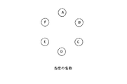
これらモニタ装置MD2〜MDnは、図2に示すように、上記遠隔会議装置TCD1を備えた会議室に居る会議参加者HM1と、他の離れた場所に居る他の会議参加者HM2〜HMn(各モニタ装置MD2〜MDnの各ディスプレイ装置上に表示されている他の会議参加者HM2〜HMn)とが、あたかも1つのテーブルを囲んで会議を行うかのように配置されている。なお、遠隔会議システムを構成している遠隔会議装置TCDが6台有り、各遠隔会議装置TCD内のモニタ装置MDが5台となるような場合、1つの遠隔会議装置TCD内の5台のモニタ装置MDの配置は、図示しているように、会議参加者HMとこれら5台のモニタ装置MDが例えば正六角形となるような配置とすることができる。
【0026】
各遠隔会議装置TCDの信号処理装置SPD内の注目度情報生成部JBは、以下に述べるようにして、会議中において動的に席替えを行う際に使用される注目度情報を生成する。
なお、以下、各遠隔会議装置TCD1〜TCDnに対応する各注目度情報生成部JB1〜JBnのうち、代表して遠隔会議装置TCD1の信号処理装置SPD1内の注目度情報生成部JB1の動作を例に挙げて説明する。
【0027】
注目度情報生成部JB1は、会議参加者HM1の例えば正面に配置されているモニタ装置MDmのカメラから供給された画像データに基づいて、会議参加者HM1の注目度を検出し、その検出結果に基づいて、後述するように動的に席順を変更するために用いられる注目度情報を生成する。
なお、会議参加者HM1における注目度とは、会議参加者HM1が前記モニタ装置MD2〜MDnの何れか或いはそれら以外の方向へ注目している場合のような注目の有無を表す場合(すなわち注目の有無をいわゆるディジタル的に0,1で表す場合)だけでなく、前記モニタ装置MD2〜MDnについてそれぞれどれくらい注目しているかを表す場合(すなわちアナログ的或いは段階的に表す場合)も含まれる。
【0028】
詳細については後述するが、注目度情報生成部JB1は、モニタ装置MDmのカメラから供給される会議参加者HM1の画像データを解折し、会議参加者HM1の向いている方向を一定のサンプリングレートで検出する。
【0029】
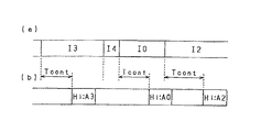
すなわち、注目度情報生成部JB1は、先ず、図3(a)に示すように、会議参加者HM1の向いている方向及びその方向の継続時間を表す情報として期間Ijを検出する。なお、この場合、Ijのjは他の各会議参加者HM2〜HMnに対応する2〜n及びそれら各会議参加者HM2〜HMnの何れでもないことを表す0のどれかの値である。注目度情報生成部JB1では、会議参加者HM2の画像が表示されているモニタ装置MD2の方を向いている期間I2、会議参加者HM3の画像が表示されているモニタ装置MD3の方を向いている期間I3、会議参加者HMmの画像が表示されているモニタ装置MDmの方を向いている期間Im、会議参加者HMn-1の画像が表示されているモニタ装置MDn-1の方を向いている期間In-1、会議参加者HMnの画像が表示されているモニタ装置MDnの方を向いている期間In等、及び、それら各モニタ装置MD2〜MDnの何れの方をも向いていない期間I0を検出する。
【0030】
次に、注目度情報生成部JB1は、それら検出した各期間I2〜In或いはI0について、特に時間Tcont以上続く期間を検出し、時間Tcont以上続く期間を検出した場合、当該検出した期間に対応する会議参加者を会議参加者HM1が注目していることを示す図3(b)のような情報(Hi:Aj)を生成する。
なお、この(Hi:Aj)のiは会議参加者HM1に対応して「1」である。またjは他の各会議参加者HM2〜HMnに対応する「2」〜「n」及びそれ以外に対応する「0」のどれかの値である。
すなわち、図3の例で説明すると、注目度情報生成部JB1は、図3(a)の各期間I2〜In或いはI0から、時間Tcont以上続く期間として期間I3とI0とI2を検出した場合、その検出した期間I3に対応する会議参加者HM3を会議参加者HM1が注目していることを示す図3(b)のような情報(Hi:A3)と、期間I0に対応して会議参加者HM1が各モニタ装置MDの何れにも注目していないこと或いは各モニタ装置MD以外のものに注目していることを示す図3(b)の情報(Hi:A0)と、期間I2に対応する会議参加者HM2を会議参加者HM1が注目していることを示す図3(b)の情報(Hi:A2)を、注目度情報として生成する。
【0031】
また、注目度情報生成部JB1では、上記各期間Ijの検出と共に、スイッチSWからのスイッチ押下情報に基づいて、注目度情報を生成するようにしてもよい。すなわちこの場合の注目度情報生成部JB1は、図4(a)に示すように、会議参加者HM1の向いている方向及びその方向の継続時間を表す情報として期間Ijを検出し、それら検出した各期間I2〜In或いはI0について、会議参加者HM1がスイッチSWを押下することにより得られる図4(b)に示すようなスイッチ押下の「ON」信号が供給されたとき、当該スイッチ押下信号が「ON」信号となっている期間に対応する会議参加者を会議参加者HM1が注目していることを示す図4(c)のような情報(Hi:Aj)を生成する。図4の例で説明すると、注目度情報生成部JB1は、図4(a)の各期間I2〜In或いはI0から、スイッチ押下信号が「ON」となされた期間としてI3とI4を検出した場合、その検出した期間I3に対応する会議参加者HM3を会議参加者HM1が注目していることを示す図4(c)のような情報(Hi:A3)と、期間I4に対応する会議参加者HM4を会議参加者HM1が注目していることを示す図4(c)の情報(Hi:A4)を、注目度情報として生成する。
【0032】
その他、会議参加者HM1の注目している方向を、当該会議参加者HM1が自ら明確に指示するようにする事も可能である。例えば、他の各会議参加者HM2〜HMnの各人毎に対応するボタンとそれらの何れにも注目していない場合に対応するボタンとを準備し、これらのボタンを当該会議参加者HM1が自ら押すことにより、自己が注目している相手を指定する。この場合、これら各ボタンの押下情報が前記注目度情報となる。
【0033】
3.席順決定装置の構成
上述のように、注目度情報生成部JB1が会議参加者HM1の挙動や指示を元に何れの会議参加者HM2〜HMnを注目しているかを検出することにより生成された注目度情報は、信号処理装置SPD1の情報送受信部TRB1に送られ、さらにネットワーク接続端子TN1を介して通信ネットワークNTから、席順決定装置GJDに送られることになる。
【0034】
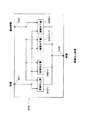
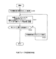
席順決定装置GJDは、図5に示すように構成されている。
この図5において、席順決定装置GJDは、通信ネットワークNTと接続されるネットワーク接続端子72と、通信ネットワークNTとの間で情報送受信を行うための情報送受信部70と、各遠隔会議装置TCD1〜TCDnから送信されてきた注目度情報に基づいて席順の決定を行うとともに、その席順を表現する席順情報を生成し、当該席順情報を各遠隔会議装置TCD1〜TCDnの情報加工配信部PBに送信する席順決定器71とを備えている。
【0035】
すなわち、当該席順決定装置GJDにおいて、情報送受信部70は、通信ネットワークNT上の信号から、各遠隔会議装置TCD1〜TCDnが送信した各注目度情報を取り出し、当該各注目度情報を席順決定器71に供給する。席順決定器71では、上記各注目度情報に基づいて、各遠隔会議装置TCD1〜TCDnを介して会議に参加している各会議参加者HM1〜HMnをどのような席順に配置すべきかを決定するとともに、その決定された席順を表す席順情報を生成する。
そして情報送受信部70では、生成された席順情報を通信ネットワークNT上に送信し、各遠隔会議装置TCD1〜TCDnに送る。
なお、詳細については後述するが、各遠隔会議装置TCD1〜TCDnでは、席順決定装置GJDから送信されてきた席順情報を情報加工配信部PBに送り、情報加工配信部PBでは、当該席順情報に基づいて後述するように会議参加者HMとモニタ装置MDの対応を決定し、例えば席順の変更がわかりやすくなるような画像、音声の加工を施した上で、各モニタ装置MD2〜MDnに対応する会議参加者HMに関する画像や音声を供給することで、決定された席順を実現する。
【0036】
4.席順決定装置におけるグループ化処理
席順決定装置GJDにおいて用いられる席順決定の方法には種々のものが考えられるが、1つの例として、まず各会議参加者HM1〜HMnが参加していると思われる会話のグループ判定を行い、その結果に基づき、同じグループに属している参加者が近くに集まるように席順を決める方式が考えられる。
そこで、グループに基づく席順決定処理の説明の前に、席順決定装置GJDにおいて行われる会話のグループを判定する処理について述べる。
【0037】
席順決定装置GJDにおいて用いられるグループ判定の基準には種々のものが考えられるが、以下では、例として、「注目している人と注目されている人の間にリンクがはられるとして、直接或いは間接にリンクで結ばれている人の集まりを1つのグループとする」という基準を用いる場合につき、上記席順決定装置GJDの席順決定器71における注目度情報に基づいたグループ判定及び更新処理の詳細について説明する。
【0038】
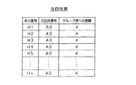
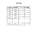
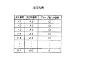
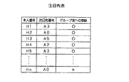
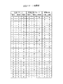
席順決定器71は、図6に示すように、当該遠隔会議システムに参加している各会議参加者に対応する番号である「本人番号」と、各遠隔会議装置TCD1〜TCDnを使用している各会議参加者HM1〜HMnが注目している相手先の会議参加者を表す番号である「注目先番号」と、グループ表への登録状態を表す「グループ表への登録」とからなる注目先表を保持する。
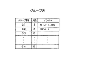
さらに席順決定器71は、図7に示すように遠隔会議システムに存在する各グループの番号を表す「グループ番号」と各グループに属する会議参加者の「人数」と各グループに属する会議参加者を表す「メンバー」とからなるグループ表を保持している。
【0039】
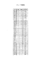
ここで席順決定器71は、注目度情報を受信する前段として、図8に示す通信開始時の初期化処理を行う。
すなわち席順決定器71は、先ず図8ステップS31の処理として、図6に示す注目先表の作成と初期化を行う。
当該初期化では、図6に示す注目先表の「本人番号」として、当該遠隔会議システムに参加している各会議参加者に対応する番号(図6の例ではH1〜Hn)を設定する。また「注目先番号」として、各遠隔会議装置TCD1〜TCDnを使用している各会議参加者HM1〜HMnが何れの相手先にも注目していないことを表す番号A0を全てに設定する。さらに「グループ表への登録」として、何れのグループにも登録されていないことを表す「×」を全てに設定する。
【0040】
同時に、席順決定器71では、ステップS32の処理として、図7に示すグループ表の作成と初期化を行う。
当該初期化では、図7に示すグループ表の「グループ番号」として、当該遠隔会議システムに参加している各遠隔会議装置TCD1〜TCDnの個々がそれぞれ一つのグループを構成しているとしてグループG1〜Gnを設定する。また「人数」として、何れのグループについて誰も参加していないとして全て「0」を設定する。さらに「メンバー」として、何れのグループについても当該グループを構成するメンバーが存在しないとして全て空にする。
【0041】
次に、席順決定器71では、注目度情報を受信すると、図9に示す注目度情報発生時の処理を開始する。
この図9において、席順決定器71では、注目度情報を受信すると、先ず、ステップS41の処理として、図10に示すように、注目先表に注目度情報を実際に反映させる。
注目度情報の反映とは、前記情報(Hi,Aj)、つまりHi番で表される会議参加者HMiが前記Aj番に相当する他の会議参加者HMjに注目しているという情報を受けて、本人番号Hiのエントリの「注目先番号」をAjにするという意味である。
またこの時「グループ表への登録」は全て「×」に初期化する。
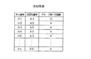
なお、図10の例では、「本人番号」H1で表される会議参加者HM1が注目する相手先として会議参加者HM3に対応するA3が「注目先番号」に設定され、「本人番号」H2の会議参加者HM2が注目する相手先として誰にも注目していないことを表すA0が「注目先番号」に設定され、同様に、会議参加者HM3が会議参加者HM5を注目することで「注目先番号」にはA5が設定され、会議参加者HM4が会議参加者HM2を注目することで「注目先番号」にはA2が設定されている。以下の説明は省略する。
【0042】
また席順決定器71では、ステップS42の処理として、グループ表について図7と同様に「人数」を全て0に設定し、「メンバー」を全て空に設定する。
【0043】
これらステップS41とS42の設定後、席順決定器71では、ステップS43の処理として、「本人番号」のH1〜Hnのそれぞれに対して、順に注目先表の内容をグループ表に反映していく。
【0044】
図11には、図9のフローチャートのステップS43における注目先表内容のグループ表への反映処理の詳細な流れを示す。なお、この図11において、「登録」とはグループ表への登録を意味し、「自エントリ」とは注目先表での自己のエントリを示し、「注目先」とは自エントリにおける注目先を示し、「注目先エントリ」とは注目先表での注目先のエントリを示し、「自グループ」とは自分がメンバーに登録されているグループを示し、「注目先グループ」とは注目先がメンバーに登録されているグループを示す。また、実際の操作における登録とは、グループ表における人数を一人増やすこと、グループ表におけるメンバーに対応番号を追加すること、注目先表おけるグループ表への登録の内容を「○」にすることである。
【0045】
先ず、上記注目先表における会議参加者Hiのエントリの反映に関する要件について説明する。本人番号Hiに対応する会議参加者HMiに関する注目先表のエントリの反映に関する要件は、先ず、本人番号Hiがグループ表に登録され、注目先表の本人番号Hiのエントリにおけるグループ表への登録が「○」となることである(以下、各遠隔会議装置におけるそのような要件を要件1と称する)。本人番号Hiの注目先番号がA0の場合(他の何れの会議参加者にも注目していない場合)には、要件はこれだけである。
【0046】
ここで、もし、本人番号Hiの注目先番号がA0でないならば、さらに注目先番号がグループ表に登録され、注目先表における注目先のエントリにおけるグループ表への登録内容が「○」となること、及び、本人番号Hiとその注目先がグループ表において同じグループに登録されていることが要件となる(以下、各遠隔会議装置におけるそのような要件を要件2と称する)。
【0047】
このような要件が満たされていることを図11のフローチャートを追いながら確認する。
先ず席順決定器71は、ステップS51の処理として、注目先表における本人番号Hiの自エントリでグループ表への登録が「○」となっているか否か判定する。当該ステップS51にて自エントリの「登録」が「○」となっていればグループ表への登録も保証されるので、要件1は既に満たされていることになる。したがって、当該ステップS51にてYESと判定した場合、席順決定器71では、本人番号Hiのグループ表への登録に関する作業は行わず、ステップS53の処理に進む。一方、席順決定器71は、自エントリで「登録」が「×」であるため、ステップS51にてNOと判定した場合、ステップS52の処理に進む。
【0048】
ステップS52の処理に進むと、席順決定器71では、グループ表において人数が0である最小の番号のグループに自己を登録(本人番号を登録)した後、ステップS53の処理に進む。
これらステップS51、ステップS52の結果、次のステップS53の処理の前には、何れにせよ要件1が満たされていることになる。
【0049】
次に、ステップS53の処理に進むと、席順決定器71は、注目先番号がA0でないか否かの確認を行う。ここで、注目先番号がA0である場合には既に全ての要件が満たされていることになるので、当該ステップS53においてNOと判定された場合、席順決定器71では処理を終了する。一方、注目先番号がA0でなく、当該ステップS53にてYESと判定されると、席順決定器71の処理は、要件2を満たすべく、ステップS54に進む。
【0050】
ステップS54の処理に進むと、席順決定器71は、注目先エントリでのグループ表への登録の内容が「○」であるか否か判断する。
ここで、注目先エントリでの登録が「×」の場合、注目先エントリがグループ表に登録されていないことが確実なので、当該ステップS54にてNOと判断すると、席順決定器71は、ステップS58の処理に進み、注目先を自己と同じグループ(自グループ)に登録し、さらに注目先表の注目先エントリにおけるグループ表への登録内容を「○」とする。このステップS58の処理により、要件2は確実に満たされるので、その後、席順決定器71は処理を終了する。
【0051】
一方、ステップS54の判定において、注目先エントリでの登録が「○」となされており、注目先が既に登録されている場合、残る要件は要件2の後半の本人番号Hiとその注目先が同じグループとなっていることの保証のみとなる。そこで、ステップS54の判定でYESと判定されると、席順決定器71は、次のステップS55においてグループ表を参照の上、ステップS56において本人番号Hiとその注目先が同じグループとなっているかどうかを確認する。
ステップS56にて既に同じグループであると確認された場合、要件2は既に満たされているので、席順決定器71は、当該ステップS56にてYESと判定された場合は処理を終了する。
【0052】
一方、ステップS56にてNOと判定した場合、本人番号Hiとその注目先の属するグループを同じにしなければならないので、席順決定器71は、ステ
ップS57の処理として、それぞれの属する2つのグループをマージする。すなわち、2つのグループのうち番号の小さい側に大きい側をマージ(小さい側の人数に大きい側の人数を加算し、小さい側のメンバーに大きい側のメンバーを追加し、大きい側の人数を0、メンバーを空に)する。この結果、要件2が満たされ、全ての要件が満たされたので、席順決定器71は、処理を終了する。
【0053】
以上で、注目先表における会議参加者Hiのエントリの反映に関する要件についての確認が終了する。
【0054】
次に、本人番号Hiのエントリに関する反映の終了後には、本人番号Hiのエントリの反映と共に、その一つ前の本人番号Hi-1までのエントリの反映がされていることが要件となる。なお、本人番号H1のエントリに関する反映に関しては、それまでに他のエントリを反映していないので、当該H1のエントリだけが反映されていればよい。
【0055】
一方、本人番号Hiのエントリを反映する場合に行う可能性のある操作は、グループ表への新規登録、グループ表における2グループのマージ、注目先表におけるグループ表への登録内容の「○」への変更であるが、この結果として本人番号Hiの一つ前の本人番号Hi-1までのエントリに従い登録した番号が消されること、グループ表への登録が「×」になることはなく、同じグループに属していた2つの番号が分断されることもない。このため、本人番号Hiについての反映処理により、その一つ前の本人番号Hi-1までの処理において満たされていた要件が満たされなくなることはない。したがって、帰納的に、全ての本人番号Hiに関し、本人番号Hiのエントリに関する図11の処理の終了後、本人番号H1からHiの全てのエントリに関する要件が満たされていることが判る。
【0056】
次に、図11に示したフローチャートの処理を行った場合の注目先表及びグループ表の内容の変遷について、具体例を挙げながら説明する。なお、ここでは、初期状態として、グループ表は図7に示したような状態となっており、また、グループ判別用情報が反映されたときの注目先表が図10のようになっている場合を例に上げ、これら注目先表とグループ表がどのように変遷するかを説明する。
【0057】
先ず、会議参加者HM1(本人番号H1)のエントリの反映について説明する。
この時、グループ表への登録内容は「×」なので、図11のステップS51においてNOと判断され、次のステップS52において本人番号H1のエントリへの登録が行われる。このステップS52の処理の結果、グループ表は、図12に示すように最小の番号のグループであるグループ番号G1について人数が1となり、メンバーには自己を表す本人番号H1が登録される。またこの時、注目先表は、図13に示すように、本人番号H1についてのグループ表への登録内容が「○」となる。
【0058】
次に、ステップS53の判定処理においてYESと判定され、注目先として例えば会議参加者HM3を表す注目先番号A3が得られた時、図13に示すように、本人番号H3のエントリのグループ表への登録内容が「×」となっているので、ステップS54の判定処理においてNOと判定され、その結果、ステップS58において当該注目先の本人番号H3が自グループであるグループG1に登録される。これにより、グループ表は、図14に示すように、グループG1について人数が2となり、そのメンバーはH1,H3となされ、また、注目先表は、図15に示すように、それら本人番号H1とH3についてのグループ表への登録内容が「○」となる。
これにより、会議参加者HM1(本人番号H1)についてのエントリの反映は終了する。
【0059】
次に、会議参加者HM2(本人番号H2)のエントリの反映について説明する。
当該本人番号H2のエントリの反映を行う場合、この時点でのグループ表への登録内容は「×」なので、図11のステップS51においてNOと判断され、次のステップS52において本人番号H2のエントリへの登録が行われる。このステップS52の処理の結果、グループ表は、図16に示すように最小の番号の次のグループであるグループ番号G2について人数が1となり、メンバーには自己を表す本人番号H2が登録される。またこの時、注目先表は、図17に示すように、本人番号H2についてのグループ表への登録内容が「○」となる。さらに、この図17の例に示すように、本人番号H2についての注目先番号が例えばA0となっている場合は、この時点でエントリの反映処理が終了する。
【0060】
次に、会議参加者HM3(本人番号H3)のエントリの反映について説明する。
当該本人番号H3のエントリの反映を行う場合、この時点でのグループ表への登録内容は先の本人番号H1のエントリ反映処理が行われている結果、図15に示すように「○」となさているので、図11のステップS51においてYESと判断され、さらに、当該本人番号H3の会議参加者HM3が例えば会議参加者HM5を注目しているとすると、ステップS53ではYESと判定される。この時点で、注目先の本人番号H5についてのグループ表への登録内容は図17に示すように「×」となっているので、図11のステップS54においてNOと判断される。
【0061】
その結果、ステップS58において当該注目先の本人番号H5は、本人番号H3についての自グループであるグループG1に登録される。これにより、グループ表は、図18に示すように、グループG1について人数が3に更新され、そのメンバーはH1,H3,H5に更新され、また、注目先表は、図19に示すように、本人番号H5についてのグループ表への登録内容は「○」に更新される。
これにより、会議参加者HM3(本人番号H3)についてのエントリの反映は終了する。
【0062】
次に、会議参加者HM4(本人番号H4)のエントリの反映について説明する。
当該本人番号H4のエントリの反映を行う場合、この時点でのグループ表への登録内容は「×」なので、図11のステップS51においてNOと判断され、次のステップS52において本人番号H4のエントリへの登録が行われる。このステップS52の処理の結果、グループ表は、図20に示すように、既に設定されているグループG1,G2の次のグループであるグループ番号G3について人数が1となり、メンバーには自己を表す本人番号H4が登録される。またこの時、注目先表は、図21に示すように、本人番号H4についてのグループ表への登録内容が「○」となる。
【0063】
次に、ステップS53の判定処理においてYESと判定され、注目先として例えば会議参加者HM2を表す注目先番号A2が得られた時、この時点での注目先表では、図21に示すように注目先である本人番号H2のグループ表への登録内容が「○」となっているので、ステップS54の判定処理においてYESと判定される。
【0064】
次に、ステップS55において当該注目先の本人番号H2についてグループ番号の探索を行うことにより、当該注目先の本人番号H2のグループ番号G2を求める。次のステップS56において、現時点での本人番号H4についてのグループ番号はG3であり、一方、注目先の本人番号H2のグループ番号G2となされているので、NOと判断され、次のステップS57において、本人番号H4についてのグループ番号G3は、より小さい番号である注目先の本人番号H2のグループ番号G2にマージされる。
【0065】
これにより、グループ表は、図22に示すように、グループG2について人数が2に更新され、そのメンバーはH2,H4に更新され、また、注目先表は、図23に示すように更新(図21のまま)される。
これにより、会議参加者HM4(本人番号H4)についてのエントリの反映は終了する。
【0066】
最後に、会議参加者HM5(本人番号H5)のエントリの反映について説明する。
当該本人番号H5のエントリの反映を行う場合、この時点でのグループ表への登録内容は図23に示したように「○」となされているので、図11のステップS51においてYESと判断され、さらに、当該本人番号H5の会議参加者HM5が例えば会議参加者HM3を注目しているとすると、ステップS53ではYESと判定される。この時点で、注目先の本人番号H3についてのグループ表への登録内容は、図23に示したように「○」となっているので、図11のステップS54においてYESと判断される。
【0067】
次に、ステップS55において当該注目先の本人番号H3についてグループ番号の探索を行うことにより、当該注目先の本人番号H3のグループ番号G1を求める。次のステップS56において、注目先の本人番号H3のグループ番号G1となされており、また、このグループ番号G1には既に本人番号H5が登録されているので、YESと判定され処理を終了する。
これにより、グループ表は、図24に示すように更新(図22のまま)、また、注目先表は、図25に示すように更新(図23のまま)される。
【0068】
以上説明したような処理により、注目先表の全ての本人番号に関する情報の反映が終わった段階で、注目先表の「グループ表への登録」は全て「○」となり、また、全ての本人番号はそれぞれグループ表においてどれか一つのグループのメンバーとして登録されていることになる。
【0069】
5.席順決定装置におけるグループ化を介する席順決定動作
以上のような処理によりグループ判定が終了すると、席順決定装置GJDは、同じグループの人は1繋がりにまとまる、という状況を実現するような席順の決定を行う。
この実現のため、席順決定装置GJDはグループ情報と共に席順情報も保持する。
グループに変更のあった際には保持している席順情報を参照し、これを図26のフローチャートに示すような処理により変更することで新しい席順を決定する。以下この内容を説明する。
【0070】
まずステップS101で、分断されているグループの有無を判断する。
変更前の席順において判定されたグループが全く分断されていない場合、即ち、すべてのグループがそれぞれ1繋がりにまとまっている場合には、目的とする状況は達成されているので変更前の席順がそのまま変更後の席順となる。つまり図26の処理はそのまま終了する。
【0071】
一方、ステップS101で分断されているグループがあると判断された場合には、ステップS102で、分断されているグループのうちグループに含まれる人数が最大のものを特定する。但し、このようなグループが複数ある際には例えばグループ番号が最小のものを分断されている最大のグループとみなす。当該最大グループは分断されているので、これはその中の1繋がりにまとまっている1人以上の人の集合をサブグループと称するとき複数のサブグループにより構成されることになる。
【0072】
分断されている最大のグループが特定されると、次にステップS103で、その中の最大のサブグループを特定し、さらに当該最大サブグループから最も近い位置にいるサブグループを特定する。但し、サブグループのうち人数が最大のものが複数ある場合には例えば含まれる個人の個人番号の最小値が小さいものを最大サブグループとして特定することとし、また、最大サブグループを基準として時計回り側、反時計回り側双方同じ近さに別々のサブグループが存在する場合には例えば反時計周り側にあるものを最も近いサブグループとして特定するものとする。
【0073】
最大サブグループから最も近いサブグループが特定されると、ステップS104で、当該特定されたサブグループを最大サブグループと連結する。この連結処理は以下のようなものである。
特定された最も近いサブグループが最大のサブグループを基準として反時計回り側に近いものであればこれを時計回りにシフトして、時計回り側に近いものであれば反時計回りにシフトして最大サブグループと繋がるようにする。但し、時計回り側と反時計回り側に同じ距離である場合には例えば時計回りにシフトして最大サブグループと繋がるようにする。この際、最大サブグループと、これと最も近いサブグループの間の席に居た人は最も近いサブグループと反対回りに最も近いサブグループの人数分だけシフトする。
以上が連結処理の詳細である。
【0074】
このような一度の連結処理により、分断されていた最大グループにおけるサブグループの数は1減るので、図26のフローチャートに沿ってループ処理することにより最終的に当該グループを1繋がりにまとめることができる。
また1つの分断されていたグループに関する処理が終わるとフローチャートに沿ってループ処理することで次に大きいグループの処理を行うことができるので、同フローチャートの処理を行うことで最終的に全てのグループがそれぞれ1繋がりにまとまり、目的の状況を達成して席順の決定処理を終えることができる。
【0075】
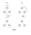
席順決定処理における席順の変遷例を以下に2つに挙げる。
1つ目の例を図27に示す。図27(a)の状態では分断されているのは黒塗りで示したグループG1のみであり、サブグループは、SG1,SG2の2つとなる。また最大のサブグループSG1から最も近いサブグループSG2は反時計回り側にある。
この場合、一度の連結処理で図27(a)の矢印に示すようにシフトが行われることで、図27(b)のように席順が更新され、席順決定の処理が完了する。
【0076】
2つ目の例を図28に示す。図28(a)の状態では分断されているグループは黒塗りで示したグループG1と白抜きで示したグループG2の2つあるが、最大のグループは黒塗りで示したグループG1である。グループG1のサブグループはSG1,SG2,SG3の3つが存在し、最大のサブグループSG1からは時計回り、反時計回り両側に同じ近さで別々のサブグループSG2,SG3がある。この場合上述したルールに従い、まず反時計回りにある側のサブグループSG3を連結するようにシフトを行う。
【0077】
この時点で図28(b)のようにサブグループはSG11,SG2の2つとなり、最大のサブグループSG11から最も近いサブグループSG2は時計回り側に存在する。
続いてそのサブグループSG2についての連結処理を行うと、当該グループG1は図28(c)のように1繋がりにまとまる。
この処理の結果もう1つの分断されていたグループG2も1繋がりにまとまるので計2回の連結処理により席順決定の処理が完了することになる。
【0078】
席順決定器71では、例えば以上のようにして席順決定の処理が完了した時点で、決定された席順を表現する席順情報を生成し、これが各遠隔会議装置TCDに送信されることになる。なお、席順情報と共に、グループ分けの状態を示すグループ情報も送信する。
【0079】
なお、席順決定器71が席順をグループ判定結果を基に決定する場合に、上記の例では、同じグループに属する会議参加者が1繋がりにまとまるようにという方針を用いていたが、同じグループの人を見る際に見渡す範囲を小さくできるよう、同じグループの人がなるべく均等に分散するようにという方針を用いることもできる。
例えば図29に示すように、グループG1,G2とされる会議参加者が、それぞれ均等に分散するように席順を決定するようにしてもよい。
【0080】
6.遠隔会議装置における席順情報に応じた席順変更処理
次に、本実施の形態の遠隔会議システムにおいて、各遠隔会議装置TDCから送信された画像データ及び音声データと、席順決定装置GJDから上述した席順情報とを受け取った遠隔会議装置TCDの動作を、以下に説明する。なお、ここでは、各遠隔会議装置TCD1〜TCDnのうち、代表して図2に示した遠隔会議装置TCD1を例に挙げてその動作を説明する。
【0081】
遠隔会議装置TCD1の情報送受信部TRBは、通信ネットワークNTを介して送信されてきた信号を受信すると、当該信号から各遠隔会議装置TCD2〜TCDnにそれぞれ対応する画像データ及び音声データを分離すると共に、上記席順情報(グループ情報も含む)を取り出し、それら分離した各画像データ及び音声データをそれぞれ情報加工配信部PB1に送ると共に、上記取り出した席順情報を情報加工配信部PB1に送る。
【0082】
情報加工配信部PB1は、上記席順情報に基づいて入力される画像及び/または音声を対応するモニタ装置MDに供給するような情報の配信を行う。配信する画像及び/または音声に対しては、例えば席順の変更内容を直観的にわかりやすくするための加工を行うことも考えられる。
【0083】
ここで、情報加工配信部PB1での具体的な処理内容について、以下に、席順の変更が直観的に分かりやすくなるような加工が画像及び音声に施され、これらが席順情報に基づく対応するモニタ装置MDに供給される場合を例にとり説明する。
【0084】
情報加工配信部PB1は図30に示すような構成をとる。即ち図2に示した情報送受信部TRB1で受信された画像及び音声を入力する入力端子201、同じく情報送受信部TRB1で受信された席順情報を入力する入力端子202、席順情報についての動き判定を行う動き判定部203、席順情報に基づいて接続状態を決定する接続決定部204、入力された画像及び音声について加工処理を行う画像加工装置205、音声加工装置206、加工処理された画像や音声を各モニタ装置MDに配信する情報配信部207が設けられる。
なお図示している情報配信部207からの出力端子TO2〜TOnは、図2に示したように各モニタ装置MD2〜MDnへ画像及び音声を供給する出力端子である。
【0085】
動き判定部203は、入力された席順情報をもとに遠隔地にいる各会議参加者HMの、その場にいる参加者HM1に対する相対的な動きの向き及び量、即ち席順の変更にかかる動きの向き及び量を判定し、その結果を動き情報として画像加工装置205及び音声加工装置206に供給する。
【0086】
画像加工装置205は図31に示すような構成をとる。即ち画像加工装置205には各会議参加者HMの画像に対応するだけ、入力される画像を加工するための画像加工器250−2・・・250−nが存在する。
画像加工器250−2・・・250−nには、入力端子251から、各会議参加者HMの画像が供給され、また入力端子252から上記動き判定部203からの動き情報が供給される。
各画像加工器250−2・・・250−nは、対応する会議参加者HMに関する動きを動き情報から抽出し、これをもとに、必要に応じ、入力された対応する会議参加者HMの画像に対し同参加者HMの移動が直観的に分かりやすいような加工処理を行う。
加工処理された各画像は、出力端子253から情報配信部207に出力される。
【0087】
各画像加工器250−2・・・250−nでの加工処理の一例としては、遠隔地にいる会議参加者HMの、その場所にいる会議参加者HM1に対する相対的な動き方向の矢印を入力画像に対し重畳するというものがある。
動き方向が左である際の入力画像と加工後の画像の例を図34(a)(b)に示す。
なお、相対的な動きがない場合には例えば矢印の重畳は行わないという方法がある。矢印の重畳は例えば後述の情報配信部207における接続変更の直前まで行う。
【0088】
また、各画像加工器250−2・・・250−nでの加工処理の他の一例としては、遠隔地にいる会議参加者HMの、その場所にいる会議参加者HM1に対する相対的な動き方向に画面内での入力画像の位置を動かして表示するというものがある。
動き方向が左である際の、入力画像を動かす直前、それから一定時間後、それからさらに一定時間後の加工後画像の例を図35(a)(b)(c)(d)に示す。動きの付加は例えば後述の情報配信部における接続変更の直前まで行う。
【0089】
さらに加工処理の他の一例としては、上記の動き付加の際に、背景は固定とし、入力画像中の会議参加者HMの部分だけを動かすというものがある。
この実現手法としては例えば遠隔地の会議参加者HMのカメラから見た背景部分をブルーバックとしておき、画像加工器250−2・・・250−nにおいて入力画像からブルーバック以外の領域を会議参加者として抜き出し、これに動きを付けて画像上に貼り付けると共に、画像上のその他の部分には固定の背景を貼り付けるというものがある。
動き方向が左である際の、入力画像を動かす直前、それから一定時間後、それからさらに一定時間後の加工後画像の例を図36(a)(b)(c)に示す。図示するようにブルーバックBBを背景として会話参加者の画像を席順の変更方向に応じて、例えば左方向に移動させる。動きの付加は例えば後述の情報配信部207における接続変更の直前まで行う。
【0090】
例えばこれらの画像加工処理は、モニタ装置MD2〜MDnで映し出される会議参加者の席順を変更させる際に、その変更を行うことや変更される方向を、参加者HM1にとってわかりやすくするものとなる。
【0091】
音声加工装置206は図32に示すような構成をとる。音声加工装置206には各会議参加者HMの音声に対応するだけ、入力される音声を加工するための音声加工器260−2・・・260−nが存在する。
音声加工器260−2・・・260−nには、入力端子261から、各会議参加者HMの音声が供給され、また入力端子262から上記動き判定部203からの動き情報が供給される。
各音声加工器260−2・・・260−nは、対応する会議参加者HMに関する動きを動き情報から抽出し、これをもとに、必要に応じ、入力された対応する会議参加者HMの音声に対し同参加者HMの移動が直観的に分かりやすいような加工処理を行う。
必要に応じて加工処理された各音声は、出力端子263から情報配信部207に出力される。
【0092】
各音声加工器260−2・・・260−nでの加工処理の一例としては、遠隔地にいる会議参加者HMがその場所にいる会議参加者HM1に対して相対的に動く場合に、音声に対して例えば”席替えします”などのメッセージ及び/または席替えを象徴するような音を重畳するというものがある。メッセージや音の重畳は例えば後述の情報配信部207における接続変更の直前、または直後まで行う。
【0093】
また加工処理の他の一例としては、遠隔地にいる会議参加者HMの動きによらず、音声に対して例えば”席替えします”などのメッセージ及び/または席替えを象徴するような音を重畳するというものがある。メッセージや音の重畳は例えば後述の情報配信部における接続変更の直前、または直後まで行う。
【0094】
図29に示した接続決定部204は、入力端子202から入力された席順情報に基づき、各画像及び音声と各モニタ装置MDの接続方法を決定し、これを接続情報として情報配信部207に供給する。
【0095】
情報配信部207は図33に示すように構成される。上記画像加工装置205から入力端子271を介して入力される画像、及び上記音声加工装置206から入力端子272を介して入力される音声は、マトリクススイッチャ270に供給される。そして、それぞれの画像及び音声は、上記接続決定部204から入力端子273を介してマトリクススイッチャ270に供給される接続情報に従って、席順情報に準ずるように各モニタ端末MDに供給される。つまりマトリクススイッチャ270は、接続情報に応じて各画像及び音声を、出力端子TO2〜TOnに振り分ける処理を行う。
【0096】
各遠隔会議装置TCDの信号処理装置SPDにおいて、情報加工配信部PBが以上のような構成とされることで、各モニタ装置MD2〜MDnにおいては、席順決定装置GJDで生成された席順情報に応じて動的に席順変更が行われることになる。
つまり会議中に離合集散する会話グループに応じて、会議参加者HM1が会話するのに好適な状況が実現されるように、モニタ装置MD2〜MDnとそこに映し出される各会議参加者HM2〜HMnの対応関係(席順)がフレキシブルに変更される。
【0097】
なお、以上の例では遠隔地の会議参加者HMに関する情報として扱われるものは画像、音声双方であったが、これを片方としても良い。
また、上記の例では画像及び音声に加工処理を行っているが、入力される画像及び/または音声を加工しないで直接情報配信部207に供給するようにしても良い。
【0098】
ところで、席順変更が頻繁に起こると各会議参加者HMがどの会話に参加しているのかの認識に混乱が生じる恐れがある。
このような事態を避けるため、上記のように席順決定装置GJDにおいてグループ判定に基づいて席順決定を行う場合に、情報加工配信部PBにおける画像処理によりグループ毎に各会議参加者HMの画像における背景を共通性のあるものに統一するような処理をする例も考えられる。
【0099】
即ち、例えば各会議参加者HMを撮像するカメラから見て背景をブルーバックにしておき、情報加工配信部PBにおいて、このブルーバックを背景として抽出し、グループ毎にこれを、例えば、同じ色の背景に変換するという例が考えられる。即ち、情報加工配信部PBはグループ情報に基づいて、各画像の背景色を設定し、画像処理を行う。色の取り決めとして、自己と同じグループに属する参加者がわかるように、自己と同じグループに属する参加者の背景を、例えば、固定の色(例えば青)とする方法も考えられる。
【0100】
図37(a)(b)に、それぞれ変換前と変換後の背景色の例を示す。図中G1〜G3はそれぞれの参加者が属するグループの番号である。この例では、図37(b)の加工後の状態として、グループG2に属する会議参加者は背景が青の参加者を自己と同一のグループと認識でき、またこの時点で、背景が赤となるグループG1と背景が緑となるグループG3が形成されていることを容易に認識できる。
【0101】
7.席順決定装置における統計的関係を用いたグループ化処理例1
席順決定装置GJDにおいて用いるグループ判定の方法として前記の例では「注目している人と注目されている人の間にリンクが張られるとして、直接あるいは間接にリンクで結ばれている人の集まりを1つのグループとする」という基準に基づくものを用いたが、他の例として各会議参加者の注目先の組み合わせの注目パターンとグループパターンの間の統計的関係からグループの判定を行うものも考えられる。
【0102】
このような手法を用いる場合、席順決定装置GJDは、図40に示すようなグループ判定表を準備しておき、注目パターンをこの表に基づきグループパターンに変換する処理例が考えられる。
以下では統計に基づきこのようなグループ判定表を予め作る際の手法の例につき説明していく。なお会議参加者が3人である場合を例に用いて説明する。
【0103】
グループ判定表を作成するためには、まず実際の会話状況を再現するような実験を行い、例えば一定周期毎に注目パターンとグループパターンの組合せからなる時系列のサンプル群を用意する。
この際、注目パターンの取得は例えば自動で行い、グループパターンについては例えば人間の判断により行うことが考えられる。
このサンプル群をもとにグループ判定表を作成する手法としては2つの手法が考えられ、まず1つ目の手法をここで説明する。
【0104】
この手法は、各注目パターンに対して最も頻度の高いグループパターンを調査し、そのようなグループパターンをそれぞれの注目パターンに対するグループパターンとして登録してやるものである。
【0105】
この方法ではまず一定時間毎に会議参加者の注目先のパターンとその時のグループパターンを記録するような実験を行うことで、図39のような注目パターンに対するグループパターンの頻度表を作成しておく。
この図39において会議参加者HM1〜HM3の下の番号は注目先の番号(但し0は誰にも注目していない場合に相当)であり、GP1〜GP5はグループパターンの番号である。
グループパターンの定義例を図38に示す。
例えば3人の会議参加者HM1〜HM3においてグループができていない状態をグループパターンGP1、会議参加者HM1、HM2がグループとなっている状態をグループパターンGP2・・・というように、図38に示すように各種のグループの形態がグループパターンGP1〜GP5として定義される。
【0106】
図39の頻度表の例は、実験結果として、例えば会議参加者HM1〜HM3の注目先が全て0である場合に、グループパターンがGP1であった頻度が10034回、グループパターンGP2の頻度が130回・・・グループパターンGP5の頻度が3024回であったことを表している。
なお、実験時のグループパターンの判定は例えばその状況を見た人間の判断に基づき行う。
【0107】
次にこのような頻度表に基づき、会議参加者HM1〜HM3の注目パターン毎にどのグループパターンである確率が最も高いかに基づき、対応するグループパターンを選択し、その対応関係を図40のグループ判定表にまとめる。
即ち図39の頻度表では、会議参加者HM1〜HM3の注目先が全て0であった場合はグループパターン=GP1の頻度が高いため、各会議参加者HM1〜HM3の注目先が「0」、即ち(0,0,0)の場合は、グループパターン=GP1とする。
また会議参加者HM3の注目先が「1」で、他の会議参加者HM1,HM2の注目先が「0」、即ち(0,0,1)の場合は、図39の頻度表からグループパターン=GP4とする。
これを全ての各人の注目先のパターンについて判定していくことで、図40のような注目先パターンとグループパターンが対応づけられることになる。
【0108】
そして席順決定装置GJDでは、予め生成された上記のようなグループ判定表を保持しておくことで、各遠隔会議装置TCDから注目度情報を受け取った際に、各会議参加者HM1〜HM3に関する注目のパターンから、グループ判定表を参照してグループの判定を行うことができ、さらにそのグループ判定に基づいて席順情報を生成できる。
【0109】
8.席順決定装置における統計的関係を用いたグループ化処理例2
上記の例では注目パターンに対するグループパターンの頻度表作成の際に全ての注目パターンを独立に扱ったが、第2の例としては、これらのうち素性の似たパターンをまとめた上で頻度表を作成し、さらに、これをもとにグループ判定表を作成する例も考えられる。
【0110】
例えば会議参加者HM1〜HM3の注目先が(0、0、2)、(0、1、0)、(0、3、0)、(2、0、0)、(3、0、0)である場合の注目の相互関係は(0、0、1)の場合の関係を回転及び/または反転したものと実質的に同等である。従って、例えば注目パターンが(0、0、2)の場合のグループパターンGP1、GP2、GP3、GP4、GP5をそれぞれ、これらに同様の反転(会議参加者HM3から会議参加者HM1とHM2の中点に向かって引く線分に関する反転)を施すことで得られる、注目パターンが(0、0、1)の場合のGP1、GP2、GP4、GP3、GP5と同等のものであるとみなして、これらを全て(0、0、1)の注目パターンにまとめた上で統計をとる、という方法が考えられる。
この場合、グループ判定表における注目パターン(0、0、1)に対応する判定グループパターンがGP1、GP2、GP3、GP4、GP5となっている場合、注目パターン(0、0、2)に対応する判定グループパターンはそれぞれの場合に対応してGP1、GP2、GP4、GP3、GP5となることになる。
【0111】
即ち第2の例は、注目パターンのうち反転や回転により一致するものの各集合を代表となる代表注目パターンにより代表させ、統計をとる際にこの代表注目パターンに関する統計とし、この統計から代表注目パターンのグループパターン判定表を作成した上で最終的に全ての注目パターンに関するグループ判定表を作成してやるものである。
このような手法を用いることで、個人性の排除や、比較的少ないサンプル数での信頼性の高い判定の実現が期待できる。
【0112】
以下で第2の例のグループ判定表の詳細な作成手順につき説明する。
まず、統計に基づくグループ判定表の作成に先立ち、予め実際の注目パターンやグループパターンから代表の注目パターン、グループパターンへの変換を行うための変換表を作成しておく。
【0113】
上記第1の例と同様に会議参加者が3人である場合を例にとって説明を行うと、作成しておく表は、図41の注目パターン変換表、図42のグループ変換表、及び図45のグループ逆変換表である。
【0114】
図41の注目パターン変換表は、注目パターンがどの代表パターンにより代表されるか、また注目パターンから代表注目パターンへはどのような変換方法により変換が行われるかを示すものである。
代表注目パターンとしてはHM1、HM2、HM3の注目先番号をそれぞれ百の位、十の位、一の位とする十進数の数字を作成した際に、最も小さい数字となるものを選ぶ。
なお、変換は全て、まず反転、その後回転の順で操作を行うとした時の反転の有無と回転の回数により表現する。反転の軸、及び回転の方向は図46(a)(b)に示す通りである。また、反転、回転の例も同図に示している。
図41の注目パターン変換表において、反転の有無はそれぞれ0、1により表現する。「0」は反転なし、「1」は反転有りである。
また回転の回数は図46(b)に示す方向への回転の数となる。
【0115】
図42のグループ変換表は上記の反転と回転を行った際に各グループパターンがどのグループパターンに変換されるかを示すものである。
即ち各グループパターンについて、反転及び回転がない場合、回転を1回行った場合、回転を2回行った場合、反転のみを行った場合、反転して回転を1回行った場合、反転して回転を2回行った場合、のそれぞれの結果として変換されるグループパターンが示される。
詳細は後述するが、これはサンプルにおける注目パターンを代表注目パターンに変換する際、この変換との整合性のあるサンプルにおけるグループパターンに対応するグループパターンを得るためのものである。
【0116】
図45のグループパターン逆変換表は、各グループパターンに対して指定された変換の逆変換を施した際にどのグループパターンになるかを示すものであり、後述する図44の代表グループ判定表から図40のグループ判定表を作成する際に用いられる。
【0117】
以下、これらの表を用いて図40のグループ判定表を作成する手法として装置構成及び作成手順につき説明する。
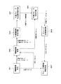
図40のようなグループ判定表を作成する装置構成としての機能ブロックを図47に示す。
なお各ブロックは、ソフトウエアでもハードウエアでも実現できる。そしてこの図47のような機能ブロックを備えたグループ判定表作成装置は、例えば席順決定装置GJDが内蔵するようにしてもよいし、席順決定装置GJDとは別体の例えばパーソナルコンピュータにおいて実現されるものでもよい。いずれにしても、最終的に作成されたグループ判定表を席順決定装置GJDが保持できるようにすれば、各遠隔会議装置TCDから注目度情報を受け取った際に、各会議参加者HM1〜HM3に関する注目のパターンから、グループ判定表を参照してグループの判定を行うことができ、さらにそのグループ判定に基づいて席順情報を生成できるものである。
【0118】
グループ判定表作成装置としては図47のように、情報取得手段301、情報変換手段302、代表頻度表作成手段303、代表グループ判定表作成手段304、代表グループ判定手段305、グループ逆変換手段306、グループ判定表作成手段307が設けられる。
【0119】
情報取得手段301は、実験で得られる各サンプルとして、注目パターン及びグループパターンを取得する。
情報変換手段302は、図41の注目パターン変換表と図42のグループ変換表を用いて、情報取得手段301で取得された上記注目パターン及びグループパターンを代表注目パターン及び代表グループパターンに変換する。
代表頻度表作成手段303は、代表注目パターン及び代表グループパターンから、図43のような代表頻度表を作成する。
代表グループ判定表作成手段304は、代表頻度表に基づいて、図44のような代表グループ判定表を作成する。
代表グループ判定手段305は、図44の代表グループ判定表を検索して、代表注目パターンに対応する代表グループパターンを判別する。
グループ逆変換手段306は、代表グループパターンをグループパターンに逆変換する。
グループ判定表作成手段307は、グループパターンと注目パターンとから、図40のグループ判定表を作成する。
なお、図47の実線矢印は、図44の代表グループ判定表を作成するまでの流れを示しており、破線矢印は、代表グループ判定表から図40のグループ判定表を作成するまでの流れを示しているものである。
【0120】
このような構成のグループ判定表作成装置では、まず最初に行うのは図43のような代表頻度表の作成である。
代表頻度表とはサンプルにおける注目パターン及びグループパターンを全て代表注目パターン及びこれへの変換と整合性のある変換を行ったグループパターン(以下、便宜上代表グループパターンと称する)に変換した上で、各代表注目パターンに対する代表グループパターンの頻度を集計した表である。
【0121】
この代表頻度表作成のための処理を図48に示す。
なお図48において「代表頻度表への登録」とは、対応する代表注目パターンと代表グループパターンの頻度に1を加算することである。
【0122】
まずステップS110において、情報取得手段301が注目パターンとグループパターンとしての最初のサンプルを取得すると、続いてステップS111で情報変換手段302は、図41の注目パターン変換表を用いて、上記サンプルとして取得した注目パターンに対応する代表注目パターンと、その代表注目パターンへの変換方法を検索する。
次にステップS112において情報変換手段302は、図42のグループ変換表を用いて、上記ステップS111で検索された変換方法に基づくグループパターンの代表グループパターンへの変換を行う。
このステップS111、S112により、取得した1つのサンプルにつき、代表注目パターンと代表グループパターンが得られる。
【0123】
続いてステップS113では代表頻度表作成手段303は、求められた代表注目パターンと代表グループパターンを図43の代表頻度表に登録する。つまり今回のサンプルとしての該当部分に「1」を加算する。
【0124】
ステップS114では全てのサンプルについての処理が終了したか否かを判断し、終了していなければステップS115で情報取得手段301が注目パターンとグループパターンとしての次のサンプルを取得してステップS111に戻り、上記同様の処理を行う。
従って全てのサンプルについてのステップS111、S112、S113の処理が終了した時点では、図43の代表頻度表が完成されていることになる。
【0125】
次に、このように生成された代表頻度表から図44の代表グループ判定表を作成する。
代表グループ判定表は各代表注目パターンに対応する代表グループパターンを記述するものであり、各エントリ(行)における代表注目パターンは代表頻度表のものと同一である。
作成の作業は各代表注目パターンに対応する代表グループパターンとして代表グループパターンのうちの各代表注目パターンに対する頻度が最大のものを登録するという内容である。作成の具体的な手順を図49に示す。
【0126】
代表グループ判定表作成手段304は、まずステップS120として、代表頻度表作成手段303で生成された代表頻度表の最初のエントリを取得する。そしてステップS121で、取得したエントリとしての代表注目パターンについて最も頻度の高い代表グループパターンを判別し、それを代表グループ判定表に登録する。
例えば図43の代表頻度表の最初のエントリでは代表注目パターン(0,0,0)について、各代表グループパターンの頻度が記述されているが、最多の頻度となるのは代表グループパターンGP1である。従って、図44の代表グループ判定表の第1行目に見られるように、代表注目パターン(0,0,0)について、代表グループパターンGP1が対応されて登録される。
【0127】
ステップS122では代表頻度表の全エントリに対して処理を終えたか否かを判断し、終えていなければステップS123で次のエントリを取得してステップS121に戻る。
また全エントリについてステップS121の処理を終えた時点で、ステップS122から処理を終える。
以上の処理により、図43の代表頻度表から図44の代表グループ判定表が生成される。なお、ここまでの処理が、図47の実線の流れに対応している。
【0128】
最後に、代表グループ判定表から図40のグループ判定表を作成する。
グループ変換表には全ての注目パターンが含まれている。グループ判定表の作成作業は、各注目パターンに対し、同じ「注目パターンと登録するグループパターンの関係」が、代表グループ判定表におけるそれぞれの注目パターンと対応する「代表注目パターンとそれに対して登録されている代表グループパターンの関係」と一致するようなグループパターンを登録するという内容である。
作成の具体的な手順を図50に示す(図47の破線の流れに対応)。
【0129】
上述したように代表グループ判定表が作成された後において、図50のステップS130で情報取得手段301は、最初の注目パターンを取得する。そしてステップS131で、その取得した注目パターンについて、情報変換手段302が図41の注目パターン変換表を用いて代表注目パターンと、その代表注目パターンへの変換方法を検索する。検索結果は代表グループ判定手段305に受けわたされる。
【0130】
次にステップS132では代表グループ判定手段305が、図44の代表グループ判定表を用いて、情報変換手段302から受け渡された代表注目パターンに対応する代表グループパターンを検索する。検索結果としての代表グループパターンはグループ逆変換手段306に受け渡される。
ステップS133ではグループ逆変換手段306が、図43のグループ逆変換表を用いて、代表グループ判定手段305から受け渡された代表グループパターンをグループパターンに逆変換する。
【0131】
ステップS134では、グループ判定表作成手段307が、上記のように情報取得手段301で取得した注目パターンと、グループ逆変換手段306から供給されたグループパターンを対応させたエントリとして、図40のグループ判定表に登録を行う。
【0132】
ステップS135では全注目パターンに対して処理を終えたか否かを判断し、終えていなければステップS136で次の注目パターンを取得してステップS131に戻る。
また全注目パターンについてのグループ判定表への登録処理を終えた時点で、ステップS135から処理を終える。
以上の処理により、図40のグループ判定表が生成される。
【0133】
以上のようにしてグループ判定に用いるグループ判定表の作成が実現され、席順決定装置GJDでは、グループ判定表を用いることでグループ分けを行い、席順情報を生成できるようになる。
【0134】
9.席順決定装置におけるグループ化を介さない席順決定動作
ここまでは、席順決定装置GJDにおける席順決定の方法として、まずグループ判定を行い、その結果に基づき席順の決定を行う例につき述べてきたが、席順決定をグループ判定を介さずに行う例も考えられる。以下にその一例につき述べる。
【0135】
席順決定装置GJDは各会議参加者HMiが他の会議参加者HMjの情報をどの程度欲しているかを表す情報要求度Rijを保持する。この情報要求度は例えば現時点に近い時点で注目していた相手の情報要求度が高いとみなし、例えばある会議参加者HMiが過去に会議参加者HM2、HM5を注目し、現在会議参加者HM3を注目している場合、この会議参加者HMiのそれぞれに対する情報要求度を図52における曲線の下の各部の面積Ri2、Ri5、Ri3とする。但し、図中の曲線は0より大きく1より小さい定数Kに関する指数関数に従う曲線である。
【0136】
より具体的には、席順決定装置GJDは一定時間毎に各会議参加者HMiが他の会議参加者HMjに注目しているかどうかを検査し、注目の有無を表す変数Aijに注目していれば1、注目していなければ0を代入する。
注目の検査が終わると席順決定装置GJDは以下の(数1)により、その時刻tにおける会議参加者HMiの会議参加者HMjに対する情報要求度を計算する。
【数1】

【0137】
続いて席順決定装置GJDは可能な全ての席順の候補(席順番号m)に関し、その席順となった場合の全会議参加者の総合的な満足度Smの計算を行う。この際に用いる計算式は以下の(数2)のようなものである。
【数2】
【0138】
図51の表は会議参加者が6人の場合の例であり表中A〜Fは席の番号に、その下の1〜6は会議参加者HM1〜HM6に対応するものである。
席順において意味のあるのは各会議参加者HMの相対位置関係であるので、例えば席AにはHM1が必ず割り当てられるものと決めておく場合、席順の数は全部で5の順列の数120となり、席順番号は1〜120となる。
【0139】
席A〜Fの配置例を図53に示す。
図51に示した満足度重みとしてのWmijの値は、例えば、席順mにおいてHMiとHMjの距離が近いほど大きくなるように設定する。より具体的には例えばHMiから数えてHMjが何番目の位置にいるかを表す数Dij_1の逆数1/Dij_1や、隣り合う席間の距離を1と定義する場合のHMiとHMjの距離を表す数Dij_2の逆数1/Dij_2を用いることが考えられる。
この場合、図54に示すような席順についてはD16_1は2であり、D16_2は√3である。
【0140】
席順決定装置GJDは最後に計算の結果最大となる満足度Smに対応する席順を採用する席順と決定する。但し、最大値をとる満足度Smが複数存在する場合には例えば、各参加者から見た他の参加者の移動量の総和の参加者全員分の和が最小となるような席順や、また別の例では席順番号が最小となるような席順を採用する席順と決定することが考えられる。
【0141】
10.遠隔会議装置における注目度情報生成動作
以上、会議参加者の注目度に応じて席順を動的に変更していく動作について各種説明してきたが、ここで、前述した図2の注目度情報生成部JB1において、会議参加者HM1の例えば正面に配置されているモニタ装置MDmのカメラから供給された画像データに基づき、会議参加者HM1が注目している方向(前記モニタ装置MD2〜MDnの何れか或いはそれら以外の方向)を検出する際の処理の具体例について説明する。
【0142】
本実施の形態の遠隔会議装置TCD1の注目度情報生成部JB1で行われる上記会議参加者HM1の注目する方向検出処理の第1の具体例としては、以下に述べるような会議参加者HM1の視線の向き検出(視線検出)を挙げることができる。
【0143】
図55には、上記注目度情報生成部JB1にて視線検出を行う場合の処理の流れを示す。
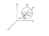
図55において、注目度情報生成部JB1は、ステップS11の処理として、例えば会議参加者HM1の正面に配されたモニタ装置MDmに設けられているカメラが撮像した画像データを受け取ると、次のステップS12の処理として、当該供給された画像の色彩情報を用いて、会議参加者HM1の顔画像における両目の輪郭を検出する。すなわち、注目度情報生成部JB1は、供給された画像の色彩情報から例えば肌、白目、黒目等の色領域を抽出し、それら抽出した色領域の例えば境界を求めること等により、図56に示すように右目の輪郭E及び左目の輪郭Eを検出する。なお、図56は片目のみを示している。
【0144】
次に、注目度情報生成部JB1は、ステップS13の処理として、ステップS12で求めた両目のそれぞれの輪郭Eに基づいて、右目の左右端点F1,F2の位置及び左目の左右端点F1,F2の位置を求め、それら右目及び左目のそれぞれの左右端点F1,F2の位置を基準として、図57に示すような鼻孔を探索するための探索範囲NEを決定し、当該探索範囲NE内から鼻孔NHの位置を検出する。すなわち、注目度情報生成部JB1は、左右両目について、図56に示すように、それぞれ目の輪郭Eを構成する画素集合の重心Qと、目の輪郭Eを構成する画素集合の2次モーメント(線に関する慣性)を最小にする線Mとを求め、さらに、目の輪郭Eを構成する画素集合の中から、上記線Mの方向において重心Qからの距離が最大距離L1,L2となる位置の画素を、重心Qから左右方向に一つずつ求め、これらの画素位置を上記左右端点F1,F2として求める。
次いで、注目度情報生成部JB1は、図57に示すように、上述のようにして求めた右目の左右端点F1,F2の位置と、左目の左右端点F1,F2の位置とを基準とし、それら各左右端点F1,F2から下方側に、鼻孔を探索するための探索範囲NEを決定する。ここで、鼻孔NH部分の画像は他の部分の画像に比べて暗く写るので、注目度情報生成部JB1は、当該探索範囲NE内で輝度が低い画像部分を鼻孔NHの位置として検出する。
【0145】
次に、注目度情報生成部JB1は、ステップS14の処理として、図58に示すように、右目の左右端点F1,F2の位置と、左目の左右端点F1,F2の位置と、鼻孔NHの位置との幾何学的な位置関係とに基づいて、眼球EBの中心位置EC及び眼球EBの半径rを推定する。
【0146】
さらに、注目度情報生成部JB1は、ステップS15の処理として、右目の輪郭E及び左目の輪郭E内の画像の輝度情報を用いて、図57に示すように、瞳孔EAの中心位置EACを検出する。
【0147】
次に、注目度情報生成部JB1は、ステップS16の処理として、図59に示すように、ステップS14で検出した眼球EBの中心位置ECと、ステップS15で検出した瞳孔EAの中心位置EACとを結ぶベクトルEVを演算し、得られたベクトルEVを視線の方向として、そのベクトルEVがモニタ部111〜113のうちのいずれを向いているかの方向判定を行う。
【0148】
以上の流れにより、注目度情報生成部JB1では、会議参加者HM1の視線を検出する。
なお、上記輪郭Eのような特定の画素集合の2次モーメントを最小にする線Mは、例えば以下のような演算により求めることができる。
ここでは、図60に示すように(数3)で表される直線Mを例に挙げる。
【数3】
また、輪郭Eの画素集合上の各点(xi,yi)と上記直線Mとの距離をRiとするとき、上記直線Mに関する2次モーメントmは、(数4)のように表すことができる。
【数4】
すなわち、2次モーメントを最小にする直線Mとは、上記(数4)のmを最小にする直線Mのことである。結論を述べると、上記(数4)のmを最小にするには、上記(数4)中のθ、ρとして、下記(数5)(数6)の条件を満たすものを使用する。
【数5】
【0151】
但し、上記(数5)(数6)において、a,b,cは下記(数7)(数8)(数9)で表される。なお、(x0,y0)は画素集合の重心である。
【数7】
次に、本実施の形態の遠隔会議装置TCD1の注目度情報生成部JB1で行われる上記会議参加者HM1の注目する方向検出処理の第2の具体例としては、以下に述べるような会議参加者HM1の顔向き検出を挙げることができる。
【0153】
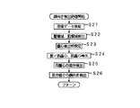
図61には、上記注目度情報生成部JB1にて顔向き検出を行う場合の処理の流れを示す。
図61において、注目度情報生成部JB1は、ステップS21の処理として、会議参加者HM1の正面に配されたモニタ装置MDmに設けているカメラから、例えば図62(A)(B)に示すような顔の原画像データが供給されると、次のステップS22の処理として、当該供給された顔画像の色彩情報を用いて、肌領域と髪領域を検出する。すなわち、注目度情報生成部JB1は、供給された顔画像の色彩情報から、例えば肌、髪の色領域を抽出し、それら抽出した色領域により、図63(A)(B)に示すように、肌領域seと髪領域heを検出する。
【0154】
次に、注目度情報生成部JB1は、ステップS23の処理として、図64(A)(B)に示すように、肌領域seと髪領域heの和領域fe(=se+he)の重心fqと、肌領域seの重心sqの検出を行うための枠の設定を行う。ここで、当該枠の設定は、画像の例えば垂直方向の範囲指定により行う。具体的に説明すると、この範囲指定は、例えば髪領域heと肌領域seの和領域feの上端reを基準とし、当該基準の上端reより下方向の区間const_aから区間const_a+const_bの間を範囲とするように行う。
【0155】
続いて、注目度情報生成部JB1は、ステップS24の処理として、ステップS23にて設定した枠の範囲内において、髪領域heと肌領域seの和領域feの重心fqと、肌領域seの重心sqを求める。なお、これら重心は、後段の処理において、水平方向成分と垂直方向成分の両方を用いる場合や、水平方向成分と垂直方向成分の何れかを用いる場合が考えられるが、ここでは一例として水平方向成分についてのみ用いる場合の例を挙げて説明する。
【0156】
注目度情報生成部JB1は、ステップS24にて髪領域heと肌領域seの和領域feの重心fqと、肌領域seの重心sqとを求めると、ステップS25の処理として、肌領域seの重心sqの値から、髪領域heと肌領域seの和領域feの重心fqの値を引いた差分値を求める。
【0157】
次に、注目度情報生成部JB1は、ステップS26の処理として、ステップS25にて求めた差分値から顔の向きを検出する。すなわち、上記差分値から顔向きを検出する処理としては、例えば以下のような2つの方法の何れかを用いる。なお、ここでは差分値をX、顔向き角度をYで表現することにし、また、会議参加者HM1がモニタ装置MDmのカメラの方向を向いている時の角度を0度と定義する。上記ステップS26の処理の一方法例では、当該顔向き検出処理に先立って、予め差分値Xと顔向き角度Yに関する統計をとり、差分値Xに対する顔向き角度Yの値を例えば平均値として求め、図65に示すようにその対応関係のグラフを用意しておき、この図65の対応関係に基づいて、ステップS25にて求めた差分値Xから顔向き角度Yを得る。また、ステップS26の処理の他の方法例では、ステップS25にて求めた差分値Xを用い、次の(数10)により顔向き角度Yを求める。
【数10】
以上の流れにより、注目度情報生成部JB1では、会議参加者HM1の顔向きを検出する。
なお、会議参加者HM1の向いている方向を検出する更に他の具体的な方法としては、例えば、会議参加者HM1の顔に赤外線を照射し、当該会議参加者HM1の顔にて反射された赤外線を受光して生成した画像を用いて、方向検出を行うような方法も考えられる。
【0159】
11.モニタ装置構成
次に、前述の図2の構成における各モニタ装置MD2〜MDnの具体的構成例について、以下の図66及び図67を用いて説明する。なお、図66はモニタ装置MDの側面側の概略的な透視図であり、図67はモニタ装置MDの概略的な正面図を表している。
なお、以下の説明では簡単のため、各遠隔会議装置TCD1〜TCDnにおいてモニタ装置MD1〜MDnにそれぞれ会議参加者HM1〜HMnに関する情報が提示される場合を例として用いる。
【0160】
本実施の形態の場合、各モニタ装置MD2〜MDnは、それぞれが図66及び図67に示すように、主要構成要素として、筐体10と、筐体10の正面(モニタ装置MDの正面)側に設けられるスピーカ13と、画面14が所定の方向(図66の例では上方)に向くように配置されたディスプレイ装置15と、ディスプレイ装置15の画面14から出た光を図中一点鎖線BOに示すように反射してモニタ装置MDの正面側に導くと共に図中二点鎖線BIに示すように当該モニタ装置MDの正面側から入射した光を透過するハーフミラー12と、上記ハーフミラー12の後方に支持部18により支持されて配されるカメラ(例えばビデオカメラ)16とを備えている。また、モニタ装置MDの例えば筐体10の上面には、支持部17により支持されたマイクロホン11が設けられている。
なお、当該マイクロホン11は、モニタ装置MD2〜MDnのうち例えば会議参加者HM1の正面に配置されているモニタ装置(図2の例ではモニタ装置MDm)にのみ設けるようにしても良い。
【0161】
各モニタ装置MD2〜MDnの各カメラ16は、図66中二点鎖線BIに示すようにハーフミラー12を透過した入射光(例えば会議参加者HM1の光像)を取り込んで画像データに変換する。これら各カメラ16から出力された画像データは、信号処理装置SPD1の情報送受信部TRB1に送られ、通信ネットワークNTを介して各遠隔会議装置TCD2〜TCDnに送られる。また、上記各モニタ装置MD2〜MDnのうち、特に、会議参加者HM1の例えば正面に配されるモニタ装置MDmのカメラ16から出力された画像データは、信号処理装置SPD1の注目度情報生成部JB1にも送られ、前述したように注目度情報生成の際の視線検出或いは顔向き検出のために用いられる。
【0162】
各モニタ装置MD2〜MDnの各マイクロホン11は、当該遠隔会議装置TCD1の周囲の音や会議参加者HM1の発言等の音を音声データに変換する。これら各マイクロホン11から出力された音声データは、信号処理装置SPD1の情報送受信部TRB1に送られ、通信ネットワークNTを介して各遠隔会議装置TCD2〜TCDnに送られる。
【0163】
また、これらモニタ装置MD2〜MDnのうち、モニタ装置MD2のディスプレイ装置15の画面14上には、遠隔会議装置TCD2において会議参加者HM1に対応して設けられているモニタ装置MD1のカメラ16により撮影されて通信ネットワークNTを介して供給されてきた画像データ(会議参加者HM2及びその周辺の画像データ)に基づく画像が表示され、また、モニタ装置MD2のスピーカ13からは、遠隔会議装置TCD2において会議参加者HM1に対応して設けられているモニタ装置MD1のマイクロホン11により取り込まれて通信ネットワークNTを介して供給された音声データ(会議参加者HM2の発言の音声データ)に基づく音声が放音される。同様に、モニタ装置MD3のディスプレイ装置15の画面上には、遠隔会議装置TCD3において会議参加者HM1に対応して設けられているモニタ装置MD1のカメラ16により撮影されて送信されてきた画像データに基づく画像が表示され、スピーカ13からは、遠隔会議装置TCD3において会議参加者HM1に対応して設けられているモニタ装置MD1のマイクロホン11により取り込まれて送信されてきた音声データに基づく音声が放音される。他のモニタ装置MDも同様であり、それぞれ対応する遠隔会議装置TCDから送られてきた画像が表示され、また音声が放音される。
【0164】
ここで、本実施の形態における各モニタ装置MD2〜MDnは、図66に示したように、上記ディスプレイ装置15の画面14から出た光が、ハーフミラー12により図中一点鎖線BOに示す方向へ反射されて会議参加者HM1側へ進むように構成されているため、上記ディスプレイ装置15の画面14上に表示される相手方の会議参加者HMの顔画像等は、上記ハーフミラー12により反射されることで本来の正しい状態に見える鏡像となされている。なお、図67の図中RVは、ディスプレイ装置15の画面14上に表示された相手方の会議参加者HMの鏡像がハーフミラー12により反射されて得られる像(相手方会議参加者HMの顔の虚像)である。
【0165】
また、本実施の形態のモニタ装置MDにおいて、ディスプレイ装置15の画面14上に相手方の会議参加者の鏡像を表示する際には、ハーフミラー14を介することで当該鏡像の目の位置と光学的に共役となる虚像の目の位置が、カメラ16のレンズの主点と略々一致するように表示を行うことにより、会議参加者HM1と相手方会議参加者HMの視線が一致するようにしている。
【0166】
すなわち、一例として、遠隔会議装置TCD1では会議参加者HM1がモニタ装置MDmの方を見ており(会議参加者HMmの画像を見ており)、遠隔会議装置TCDmでは会議参加者HMmがモニタ装置MD1の方を見ている(会議参加者HM1の画像を見ている)場合を例に挙げて説明すると、この例の場合、遠隔会議装置TCD1のモニタ装置MDmのディスプレイ装置15の画面14上に表示されるのは会議参加者HMmの顔等の鏡像であり、当該モニタ装置MDmのカメラ16では当該モニタ装置MDmの方を向いている会議参加者HM1の画像が取り込まれ、その画像データが遠隔会議装置TCDm等に送られることになる。また、この例の場合、遠隔会議装置TCDmのモニタ装置MD1のディスプレイ装置15の画面14上に表示されるのは会議参加者HM1の顔等の鏡像であり、当該モニタ装置MD1のカメラ16では当該モニタ装置MD1の方を向いている会議参加者HMmの画像が取り込まれ、その画像データが遠隔会議装置TCD1等に送られることになる。
このような状態となっている場合において、遠隔会議装置TCD1側では、モニタ装置MDmのディスプレイ装置15の画面14上に相手方の会議参加者HMmの鏡像を表示する際に、当該鏡像の目の位置と光学的に共役となる虚像の目の位置がカメラ16のレンズの主点と略々一致するように表示を行うようにし、同時に、遠隔会議装置TCDm側では、モニタ装置MD1のディスプレイ装置15の画面14上に相手方の会議参加者HM1の鏡像を表示する際に、当該鏡像の目の位置と光学的に共役となる虚像の目の位置がカメラ16のレンズの主点と略々一致するように表示を行うようにすることにより、遠隔会議装置TCD1側では会議参加者HM1の視線と相手方会議参加者HMmの虚像の視線とが一致するようになり、また、遠隔会議装置TCDmでは会議参加者HMmの視線と相手方会議参加者HM1の虚像の視線とが一致するようになる。
【0167】
なお、一般的な従来の遠隔会議システムでは、本実施の形態のようにハーフミラーによる虚像ではなくディスプレイ装置の画面上に表示された画像(実像)を会議参加者が直接見るようになされており、また、カメラは例えばディスプレイ装置の画面の上下左右何れかの近傍に配置されることになる。したがって、一般的な従来の遠隔会議システムの場合、会議参加者の視線はディスプレイ装置の画面上に表示された画像(実像)上に向けられ、カメラのレンズから外れた方向に向くことになる。このため、ディスプレイ装置の画面上に表示される相手方の会議参加者の視線は、自分の方を向いているようには見えないことになり、本実施の形態の場合のように互いに視線を一致させて会話を行うようなことは出来ない。
【0168】
これに対して、本実施の形態の遠隔会議システムにおいては、各遠隔会議装置TCDのモニタ装置MDを、図66及び図67に示すような構成とすることにより、上述したように、会議参加者とその相手方の会議参加者の双方が互いに相手方の目を見ながら、すなわち視線を一致させた状態で、会話をすることが可能となっている。
【0169】
また、本実施の形態においては、遠隔会議装置TCD内の複数のモニタ装置MDを、図2に示すように各遠隔会議装置TCD2〜TCDnの会議参加者HM2〜HMnが会議参加者HM1と共にテーブルを囲んでいるような状態に配置した場合、すなわち、各遠隔会議装置TCD2〜TCDnの各地点における会議参加者HM2〜HMnの相対的な位置関係が保存されているような状態に配置した場合、会議参加者HM1と相手方の会議参加者との間で上述したような視線一致を実現できるだけでなく、他の会議参加者HMがそれぞれ誰の方を向いているのかをも確認できるようになる。
【0170】
12.各装置の構成例
次に、図68には、本発明実施の形態の遠隔会議システムにおける各遠隔会議装置TCDの信号処理装置SPDや席順決定装置GJDを実現する実際の装置構成例を示す。なお、これら装置は、例えばパーソナルコンピュータ等にて実現することができる。また、上述した図47のようなグループ判定表作成装置も、以下に述べる装置構成で実現できる。
【0171】
この図68に示す構成は、各部を制御するCPU100と、例えばBIOS(Basic Input Output Systems)や各種の初期値等が格納されたROM101と、各種のプログラムやデータ、演算途中のデータ等を一時的に記憶するRAM102と、OS(オペレーティングシステム)や各種アプリケーションプログラム(コンピュータプログラム)、その他のデータ等を格納するハードディスクを駆動するハードディスクドライブ(HDD)104と、CD−ROMやCD−R、CD−RW、DVD−ROM、DVD−RAM、DVD−R、DVD−RW、着脱可能はハードディスクや半導体メモリなどの各種のリムーバブルメディア106が装填されるメディアドライブ105と、前記ISDN、一般電話回線、ケーブルテレビ回線、ディジタル通信衛星回線などの外部通信網(前記通信ネットワークNT)と接続したり、IEEE1394規格やUSB等の外部バス、各種の外部接続端子に接続するための通信インターフェイス(I/F)部103などを備えている。
なお、図示しないが、図68に示す構成は、更に例えばユーザにより操作されるマウスやキーボード等の入力操作装置や情報を表示するためのモニタ等を備えることも可能である。
【0172】
ここで、上述した本実施の形態の遠隔会議システムにおける信号処理装置SPDの機能、特に、注目度情報生成部JBでの注目度情報生成機能や情報加工配信部PBでの情報加工配信機能、或いは、席順決定装置GJDのおけるグループ判定処理や席順決定処理及び席順情報の生成機能等を実現するためのアプリケーションプログラムは、リムーバブルメディア106により、或いは通信インターフェイス部103を介する通信により提供される。
【0173】
これらリムーバブルメディア106や通信インターフェイス部103により提供されたアプリケーションプログラムは、HDD104内のハードディスクに格納され、当該HDD104のハードディスクから読み出されてRAM102に一時的に格納され、これにより、CPU100は、当該RAM102に一時的に記憶されたアプリケーションプログラムに応じて、前述したような本実施の形態の遠隔会議システムにおける各種の動作を実行する。
【0174】
次に、図69には、遠隔会議装置TCD1の他の構成例を示す。
この図69に示す構成例では、他の遠隔会議装置TCD2〜TCDnの各会議参加者HM2〜HMnの画像を映しだす表示手段として、前述の図2に示したような他の各遠隔会議装置TCD2〜TCDn(他の会議参加者HM2〜HMn)それぞれに対応したモニタ装置MD2〜MDnを設けるのではなく、例えば湾曲した1つのスクリーン31を設け、当該スクリーン31に例えばプロジェクタにより画像を表示するようにしている。
【0175】
すなわちこの図69の構成例では、会議参加者HM1と共に他の各会議参加者HM2〜HMnがあたかも1つのテーブルを囲んで会議を行うかのように、スクリーン31上にそれら他の各会議参加者HM2〜HMnの画像が表示される。
【0176】
カメラ34及びマイクロホン35は、例えば会議参加者HM1の正面に置かれ、当該カメラ34により撮像された会議参加者HM1の画像データとマイクロホン35により集音された会議参加者HM1の音声データは、前記通信ネットワークNTを介して、他の各遠隔会議装置TCD2〜TCDnに送信される。また、この図69の構成例において、カメラ34で撮像された会議参加者HM1の画像データは、前記信号処理装置SPD1の注目度情報生成部JB1にも送られる。
【0177】
一方、他の各遠隔会議装置TCD2〜TCDnから送信されてきた各会議参加者HM2〜HMnの音声データは、それら個々の音像がスクリーン31上に表示されている各会議参加者HM2〜HMnの画像近傍に定位するように制御されて、スクリーン31の左右に配置されたスピーカ32,33に供給され、放音される。これにより、スクリーン31上に表示された各会議参加者HM2〜HMnの画像位置と、それら各会議参加者HM2〜HMnの発言(音声)が聞こえてくる位置は略々一致することになる。
【0178】
なお、本実施の形態では、注目度情報生成部JBを個々の遠隔会議装置TCD1〜TCDnの信号処理装置SPD1〜SPDn内に設けた例を挙げたが、通信ネットワークNT上に独立して例えば一つ設けることも可能である。
【0179】
また、本実施の形態では、図2に示したように、各モニタ装置MD2〜MDnと信号処理装置SPD1を別構成としたが、各モニタ装置MD2〜MDnのそれぞれ或いは一つに信号処理装置の機能を持たせることも可能である。
【0180】
さらに、本実施の形態では、図1に示したように、席順決定装置GJDを独立して通信ネットワークNTに接続するようにしているが、各遠隔会議装置TCD1〜TCDnのそれぞれ或いは一つに当該席順決定装置の機能を持たせることも可能である。
【0181】
また、本実施の形態では、方向検出の具体例として視線と顔向き検出をそれぞれ別個に行う例を挙げたが、それら両方の方向検出を同時に行うことも可能である。
【0182】
その他、本実施の形態では、一人の会議参加者が所属できるグループを各時刻において一つとした例を挙げているが、それ以外に、例えば主に属しているグループ、発言はしないが情報は得たいグループなど、複数のグループを定義しておき、各人の会議参加者を複数のグループに所属可能とし、相手方の会議参加者の各人がどのグループに属しているかにより、席順決定を行うようにする例も考えられる。
【0183】
以上説明したように、本実施の形態の遠隔会議システムによれば、複数の会議参加者が同時に発言するような場合でも、自己が属するグループの発言を聞きやすくなり、また、画像も見やすくなり、したがって、各会議参加者において情報の充足と快適さを与える遠隔会議システムを実現することができる。
【0184】
【発明の効果】
以上の説明から理解されるように本発明によれば、3以上の複数の通信装置間で通信を行う場合に、各通信装置が送信する情報に対する席順情報を生成し、各通信装置に送信する席順決定装置を有し、各通信端末は席順情報に応じて各情報の出力位置を制御することで、他の通信装置から送信されてきた各情報が上記席順情報に応じた席順で出力されるようにしている。従って遠隔会議システムなどとして適用することで、会議の進行や会話の状況に応じて自動的に常に最適な状態に席順が変更されるため、ユーザにとって快適な会議環境、通信環境を実現できるという効果がある。
また席順決定は、上記各通信装置が送信する情報に対する上記各通信装置の各ユーザの注目度に応じて生成することで、最適な席順を実現できる。
【0185】
さらに席順決定は、上記注目度に基づいて上記各通信装置が送信する各情報をグループ分けし、そのグループ分けの結果に基づいて生成することで、会話中のグループを考慮した席順変更が自動的に実現され、遠隔会議システムとして好適である。
その際に、同じグループとされた各情報が並ぶように席順情報が生成されることで、グループ毎にまとめるような席順変更ができる。
或いは同じグループとされた各情報が略均等に分散するように席順情報が生成されることで、ユーザにとって会話のしやすい環境を実現できる。
【0186】
また各通信装置は、席順情報に応じて席順を変更する際には、当該席順の変更をユーザに提示する提示情報を、例えば画像情報や音声情報で出力することで、席順変更が行われることがユーザが認識でき、席順変更によってユーザが混乱することがなくなる。
さらにグループに基づいて席順を変更させる場合は、グループ分けの状態をユーザに提示する提示情報を出力することで、ユーザは会話グループの状態を良好に認識でき、これもユーザの状況認識を助けることができる。例えば背景画像の色などとすることが最もわかりやすい提示となる。
【0187】
また上記注目度は、ユーザの挙動検出情報もしくはユーザによる指示情報に基づいて決定することで、席順変更の基準となる情報として好適なものとなる。具体的には挙動検出情報としてユーザの視線や顔向きに基づくことは、ユーザの自然な動作を利用した最適な制御を実現できるものとなる。
【0188】
また上記グループ分けは、上記各通信装置の各ユーザの他の通信装置から送信されてきた各情報に対する注目度の状態と、グループ構成との間の統計的関係に基づいて行われることでも、席順情報の生成に対して適切なものとなる。
このため本発明のグループ判定表作成方法、グループ判定表作成装置により上記統計的関係を把握しておくことで、席順変更について好適な動作を実現できる。
【図面の簡単な説明】
【図1】本発明の実施の形態の遠隔会議システムの構成のブロック図である。
【図2】実施の形態の遠隔会議装置のブロック図である。
【図3】実施の形態の注目度情報の生成方式の説明図である。
【図4】実施の形態の注目度情報の他の生成方式の説明図である。
【図5】実施の形態の席順決定装置のブロック図である。
【図6】実施の形態の注目先表の初期状態の説明図である。
【図7】実施の形態のグループ表の初期状態の説明図である。
【図8】実施の形態の注目先表及びグループ表の初期化処理のフローチャートである。
【図9】実施の形態の注目度情報発生時の処理のフローチャートである。
【図10】実施の形態の注目度情報を反映させたときの注目先表の説明図である。
【図11】実施の形態の注目先表の内容をグループ表へ反映させる処理のフローチャートである。
【図12】実施の形態の処理過程のグループ表の説明図である。
【図13】実施の形態の処理過程の注目先表の説明図である。
【図14】実施の形態の処理過程のグループ表の説明図である。
【図15】実施の形態の処理過程の注目先表の説明図である。
【図16】実施の形態の処理過程のグループ表の説明図である。
【図17】実施の形態の処理過程の注目先表の説明図である。
【図18】実施の形態の処理過程のグループ表の説明図である。
【図19】実施の形態の処理過程の注目先表の説明図である。
【図20】実施の形態の処理過程のグループ表の説明図である。
【図21】実施の形態の処理過程の注目先表の説明図である。
【図22】実施の形態の処理過程のグループ表の説明図である。
【図23】実施の形態の処理過程の注目先表の説明図である。
【図24】実施の形態の処理過程のグループ表の説明図である。
【図25】実施の形態の処理過程の注目先表の説明図である。
【図26】実施の形態の席順決定処理のフローチャートである。
【図27】実施の形態の席順決定の例の説明図である。
【図28】実施の形態の席順決定の例の説明図である。
【図29】実施の形態の分散的な席順決定の例の説明図である。
【図30】実施の形態の情報加工配信部のブロック図である。
【図31】実施の形態の画像加工装置のブロック図である。
【図32】実施の形態の音声加工装置のブロック図である。
【図33】実施の形態の情報配信部のブロック図である。
【図34】実施の形態の席順移動時の画像処理例の説明図である。
【図35】実施の形態の席順移動時の画像処理例の説明図である。
【図36】実施の形態の席順移動時の画像処理例の説明図である。
【図37】実施の形態のグループ提示のための画像処理例の説明図である。
【図38】実施の形態のグループパターンの説明図である。
【図39】実施の形態の注目パターン対グループパターン頻度表の説明図である。
【図40】実施の形態のグループ判定表の説明図である。
【図41】実施の形態の注目パターン変換表の説明図である。
【図42】実施の形態のグループ変換表の説明図である。
【図43】実施の形態の代表頻度表の説明図である。
【図44】実施の形態の代表グループ判定表の説明図である。
【図45】実施の形態のグループ逆変換表の説明図である。
【図46】実施の形態のグループ変換方法の説明図である。
【図47】実施の形態のグループ判定表作成装置の機能的なブロック図である。
【図48】実施の形態の代表頻度表の作成処理のフローチャートである。
【図49】実施の形態の代表グループ判定表の作成処理のフローチャートである。
【図50】実施の形態のグループ判定表の作成処理のフローチャートである。
【図51】実施の形態の満足度重み表の説明図である。
【図52】実施の形態の各人物に対する注目度の例の説明図である。
【図53】実施の形態の席の名称の説明図である。
【図54】実施の形態の席順の例の説明図である。
【図55】実施の形態の視線検出処理の流れを示すフローチャートである。
【図56】実施の形態の目の両端位置検出の説明図である。
【図57】実施の形態の鼻孔の位置検出範囲の説明図である。
【図58】実施の形態の目の両端位置、鼻孔位置、眼球中心位置の説明図である。
【図59】実施の形態の視線の方向検出の説明図である。
【図60】実施の形態の特定の画素集合の2次モーメントを最小にする線の求め方の説明図である。
【図61】実施の形態の顔向き検出処理のフローチャートである。
【図62】実施の形態の顔向き検出の際の原画像の説明図である。
【図63】実施の形態の顔向き検出の際の髪領域と肌領域の説明図である。
【図64】実施の形態の髪領域と肌領域の重心の説明図である。
【図65】実施の形態の顔向き検出の際の差分値と角度の関係例の説明図である。
【図66】実施の形態の具体例のモニタ装置を側面側から見た概略的な透視図である。
【図67】実施の形態の具体例のモニタ装置の概略的な正面図である。
【図68】実施の形態の遠隔会議システムにおける各遠隔会議装置の信号処理装置や席順決定装置を実現する実際の装置構成例を示すブロック構成図である。
【図69】実施の形態の遠隔会議装置の他の例として、スクリーン上に会議参加者の画像を表示し、スピーカによる音像を定位させる場合の概略構成の説明図である。
【符号の説明】
HM 会議参加者、TCD 遠隔会議装置、NT 通信ネットワーク、GJD席順決定装置、SPD 信号処理装置、TRB 情報送受信部、PB 情報加工配信部、MD モニタ装置、SW スイッチ、71 席順決定器、16 カメラ、11 マイクロホン、12 ハーフミラー、15 ディスプレイ装置、13スピーカ、100 CPU、101 ROM、102 RAM、103 通信インターフェイス部、104 HDD、105 リムーバブルメディアドライブ、 106 リムーバブルメディア[0001]
BACKGROUND OF THE INVENTION
The present invention relates to a communication system for performing communication between three or more communication devices.InSeat order determination equipmentIn placeRelated. In addition, seat order determination equipmentIn placeThe present invention relates to a group judgment table creation method and a group judgment table creation device for creating a group judgment table to be used.
[0002]
[Prior art]
Conventionally, in a teleconferencing system, images and sounds in a plurality of distant conference rooms are communicated with each other via a network, and each conference room reproduces images and sounds of other conference rooms as if 1 It is possible to hold a conference as if it were surrounding two tables.
[0003]
[Problems to be solved by the invention]
By the way, in the conventional remote conference system, the conference participants in each conference room can speak simultaneously.
Here, during an actual conference, among the participants, there are some conversation groups depending on the progress of the conference, and the topic may be different for each group. In addition, such a group is formed temporarily by some conference participants on a certain topic, and the group is fluid. In other words, it changes from moment to moment, such as a conversation group is formed as the conference progresses, the members of the group change, or one group is further divided into a plurality of groups.
[0004]
In the remote conference system, each participant sees the appearance of the other participants through the monitor device, but in the conventional system, the correspondence between the participants displayed as each monitor device is fixed. For example, in a system with six participants, each participant sees the other five people on five monitor devices, and each monitor device displays a specific conference participant. That is, in a remote conference terminal used by a certain participant, other participants HMa, HMb, HMc, HMd, and HMe are always fixedly displayed on the five monitor devices MDa, MDb, MDc, MDd, and MDe, respectively. It will be in the state.
Here, if each monitor device is considered to be a “seat” of another conference participant, it is possible to change the seat order to some extent.
That is, for example, for each of the five monitor devices MDa, MDb, MDc, MDd, and MDe arranged in order, the participants HMa, HMb, HMc, HMd, and HMe are not fixed, The response of the participant can be changed.
As a result, for example, when the above-described group occurs, it is conceivable to perform “change seats” by meeting the group. For example, when the user of the terminal and the participants HMb and HMd form a group, the seats are changed so that the correspondence is changed so that the participant HMb is displayed on the monitor device MDa and the participant HMd is displayed on the monitor device MDb. , Can create a convenient state for conversation within the group.
[0005]
However, such a change of “seat” is realized, for example, by changing the seating order by the participant performing an instruction operation to change the seating order. In addition, it is not realistic for the user to change seats. That is, a very complicated operation is required from the user. In particular, the user wants to concentrate on the conference without performing any operation during the conference. Furthermore, terminal users are not necessarily used to the operation.
In addition, it is possible to have a person in charge as a system operator to perform a seat change operation, but it requires extra manpower and the operator cannot accurately grasp the conversation group that changes every moment. It is also not practical.
For these reasons, even in a system that can change the order of seats, most of the functions are not utilized.
[0006]
[Means for Solving the Problems]
The present invention has been made in view of such a situation, and in a teleconference system or the like, a communication system that can realize an appropriate “seat order change” in accordance with a conversation situation that proceeds flexibly between participants. It is an object of the present invention to provide a more suitable communication conversation environment.
[0007]
this3 or moreIn the communication system that performs communication between the plurality of communication devices, the communication device includes a seat order determination device that generates seat order information at each time point for information transmitted by each communication device and transmits the information to each communication device.
The seat order determination device generates seat order information for each time point for information transmitted by the plurality of communication devices according to the degree of attention of each user of the communication devices with respect to information transmitted by the communication devices. .
Further, the seat order determining device divides each information transmitted by each communication device based on the degree of attention of each user with respect to the information transmitted by each communication device, and the seat order information based on a result of the grouping. Is generated.
Each of the communication devices controls the output position of each information transmitted from another communication device according to the seat order information, so that each information transmitted from the other communication device is included in the seat order information. Output in the order of the corresponding seats.
Furthermore, when changing the seating order according to the seating order information, presentation information for presenting the change of the seating order to the user is output.
Also, presentation information for presenting the grouping status to the user is output.
[0008]
The seat order determination apparatus according to the present invention includes a seat order information generating unit that generates seat order information at each time point for information transmitted by each communication device, and the seat order information generated by the seat order information generating unit. Means to send toAnd aboveReceiving means for receiving attention level information indicating the attention level of each user of each communication device with respect to information transmitted by each communication deviceThe
AndThe seat order information generating means groups each information transmitted by the communication devices based on the attention level information received by the receiving means, and generates the seat order information based on the grouping result.
The grouping is performed on the basis of a statistical relationship between the state of interest for each piece of information transmitted from another communication device of each user of each communication device and the group configuration.
[0012]
Further, the group determination table creation method of the present invention includes an attention level pattern indicating a level of attention level for each piece of information transmitted from another communication device of each user of each communication device, and a group configuration indicating the group status of each user From the sample with the pattern, the statistics about the relationship are taken, and from the statistical result, the correspondence relationship of each one of the group configuration patterns is determined for each attention degree pattern, and the attention degree pattern for which the correspondence relationship is determined and the above By registering the group configuration patterns, a group determination table in which a specific group configuration pattern is associated with each attention degree pattern is created.
The statistics are obtained as a sample of a representative attention pattern having a plurality of attention patterns that are substantially the same pattern. In determining the correspondence, the representative attention pattern and the representative corresponding to the representative attention pattern are determined. After the group pattern is determined, one group configuration pattern corresponding to each attention level pattern is determined based on the determination.
[0013]
The group determination table creation device according to the present invention includes an attention level pattern indicating a level of attention to each piece of information transmitted from another communication device of each user of each communication device, and a group configuration indicating a group status of each user A statistical means for taking a sample with a pattern and taking statistics about the relationship; and a determination means for determining a correspondence relationship between each group configuration pattern for each attention level pattern from a statistical result obtained by the statistical means; The determination table creation that creates a group determination table in which a specific group configuration pattern is associated with each attention level pattern by registering the attention level pattern and the group configuration pattern for which the correspondence is determined by the determination unit Means.
The statistical means takes statistics of a plurality of attention level patterns that are substantially the same pattern as one representative attention level pattern sample, and the determination means determines the representative attention level pattern and a representative group pattern corresponding thereto. Is determined, and the correspondence relationship of one group configuration pattern is determined for each attention degree pattern based on the determination.
[0014]
DETAILED DESCRIPTION OF THE INVENTION
Hereinafter, embodiments in which the present invention is applied to a remote conference system will be described in the following order.
1. Communication system configuration
2. Configuration of remote conferencing equipment
3. Configuration of seat order determination device
4). Grouping process in seat order determination device
5. Seat order determination operation through grouping in the seat order determination device
6). Seat order change processing according to seat order information in remote conference equipment
7). Grouping processing example 1 using statistical relationship in seat order determination device
8). Grouping processing example 2 using statistical relationship in seat
9. Seat order determination operation without grouping in the seat order determination device
10. Attention level information generation operation in a remote conference device
11. Monitor device configuration
12 Configuration example of each device
[0015]
1. Communication system configuration
FIG. 1 shows a schematic configuration of a remote conference system as an embodiment to which the present invention is applied. In the present specification, the system means an overall configuration of a plurality of devices and units.
[0016]
In the remote conference system of the embodiment shown in FIG. 1, remote conference devices TCD1 to TCDn corresponding to the conference participants HM1 to HMn at a plurality of locations (1 to n locations) are assigned, respectively. The conference apparatuses TCD1 to TCDn are connected via a communication network NT made up of, for example, ISDN (Integrated Services Digita1 Network).
Hereinafter, when it is not necessary to individually distinguish each conference participant HM1 to HMn, it is simply referred to as a conference participant HM. Similarly, when it is not necessary to individually distinguish each remote conference device TCD1 to TCDn. Is simply referred to as a remote conference device TCD. In FIG. 1, ISDN is taken as an example of the communication network NT, but other transmission media such as a cable television network, the Internet, and digital satellite communication can be used instead of ISDN.
[0017]
Each remote conference device TCD takes in the image data and audio data of the corresponding conference participant HM, communicates with each other remote conference device TCD via the communication network NT, and from other remote conference devices TCD. The transmitted image data and audio data of other conference participants HM can be reproduced (image and audio can be monitored).
[0018]
2. Configuration of remote conference equipment
Each remote conference device TCD constituting the remote conference system has a configuration as shown in FIG.
Each of the remote conference apparatuses TCD1 to TCDn has the same configuration. FIG. 2 shows a detailed configuration example of the remote conference apparatus TCD1 as a representative of the plurality of remote conference apparatuses TCD1 to TCDn. Is shown.
[0019]
The teleconference device TCD1 is connected to the communication network NT and transmits / receives signals to / from other remote conference devices TCD2 to TCDn constituting the remote conference system. The image data and audio data of the conference participants HM2 to HMn transmitted from the signal processing device SPD1 that performs the signal processing and the other remote conference devices TCD2 to TCDn constituting the remote conference system are It is configured to include at least monitor devices MD2 to MDn capable of monitoring corresponding to the conference devices TCD2 to TCDn, respectively.
Hereinafter, when there is no need to distinguish between the monitor devices MD2 to MDn, they are simply described as the monitor device MD.
[0020]
Here, the users of the remote conference devices TCD1 to TCDn are fixed to the conference participants HM1 to HMn, but the correspondence between the monitor device MD in each remote conference device and the information of the conference participant HM presented there Is not fixed, but its correspondence changes dynamically according to seat order information described later.
However, for the sake of simplicity, the description will be made assuming that the monitor devices MD1 to MDn correspond to the conference participants HM1 to HMn in each of the remote conference devices TCD1 to TCDn before the description of changing the seat order.
[0021]
The signal processing device SPD1 of the remote conference device TCD1 includes a network connection terminal TN1 connected to the communication network NT, an information transmission / reception unit TRB1 for transmitting / receiving information to / from the communication network NT, and monitor devices MD2 to MDn. An information processing / distribution unit PB1 that performs an information processing / distribution process, which will be described later, on a signal to be sent, and an attention level information generation unit that generates attention level information used to dynamically change the seating order during a meeting as will be described JB1, output terminals TO2 to TOn of signals individually sent to the monitor devices MD2 to MDn, input terminals TI2 to TIn of signals individually supplied from the monitor devices MD2 to MDn, and generation of the attention degree information And an input terminal TS of a signal from a switch SW for generating switch pressing information, which will be described later.
[0022]
Each of the monitor devices MD2 to MDn will be described in detail later. As main components, each of the monitor devices MD2 to MDn has a speaker provided on the front side of the housing of the monitor device MD and a screen G in a predetermined direction (for example, a participant HM1). And a display device arranged to face in the opposite direction.
In addition, in at least one monitor device MD among the monitor devices MD2 to MDn, a microphone for capturing sounds around the remote conference device TCD1 and the conference participant HM1 and an image of the conference participant HM1 are captured. Cameras (for example, video cameras).
The monitor device provided with the microphone and the camera is preferably provided in a monitor device (monitor device MDm in the example of FIG. 2) disposed in front of the conference participant HM1. Of course, all the monitor devices MD2 to MDn can be provided with a microphone and a camera.
[0023]
The image data captured from the camera in the monitor device MD and the audio data captured from the microphone are sent to the other remote conference devices TCD2 to TCDn via the signal processing device SPD1 and the communication network NT.
[0024]
In addition, images based on the image data sent from the remote conference devices TCD2 to TCDn are displayed on the display devices of the monitor devices MD2 to MDn, respectively, and sent from the remote conference devices TCD2 to TCDn from the speakers, respectively. Audio based on the received audio data is output.
That is, the monitor devices MD2 to MDn are associated with the remote conference devices TCD2 to TCDn in a 1: 1 ratio. And, for example, on the screen G of the display device of the monitor device MD2, image data photographed by the camera of the remote conference device TCD2 and supplied via the communication network NT (conference participant HM2 and surrounding image data) In addition, the audio data supplied from the speaker of the monitor device MD2 by the microphone of the remote conference device TCD2 and supplied via the communication network NT (audio data of the speech of the conference participant HM2) is displayed. A sound based on is emitted.
Similarly, an image based on image data captured and transmitted by the camera of the remote conference device TCD3 is displayed on the screen of the display device of the monitor device MD3, and is captured from the speaker by the microphone of the remote conference device TCD3. The voice based on the voice data transmitted is transmitted. The same applies to the other monitor devices MD, in which images sent from the corresponding remote conference devices TCD are displayed and sound is emitted.
However, as described above, the correspondence between the monitor devices MD2 to MDn and the remote conference devices TCD2 to TCDn is not fixed in this example, and the correspondence relationship is dynamically changed as a so-called seat order change. Therefore, the above correspondence is a provisional correspondence in the initial state of the system, for example.
The image data transmitted and received between the remote conference devices TCD1 to TCDn via the communication network NT may be still image data in addition to the example of moving image data.
[0025]
As shown in FIG. 2, these monitor devices MD2 to MDn include a conference participant HM1 in a conference room equipped with the remote conference device TCD1, and other conference participants HM2 to HMn in other remote locations (each Other conference participants HM <b> 2 to HMn) displayed on the display devices of the monitor devices MD <b> 2 to MDn are arranged as if having a conference surrounding a single table. When there are six remote conference devices TCD constituting the remote conference system and there are five monitor devices MD in each remote conference device TCD, five monitors in one remote conference device TCD. As shown in the figure, the device MD can be arranged such that the conference participant HM and these five monitor devices MD are, for example, regular hexagons.
[0026]
The attention level information generation unit JB in the signal processing device SPD of each remote conference device TCD generates attention level information used when dynamically changing seats during the conference as described below.
Hereinafter, of the attention level information generation units JB1 to JBn corresponding to each of the remote conference devices TCD1 to TCDn, the operation of the attention level information generation unit JB1 in the signal processing device SPD1 of the remote conference device TCD1 will be exemplified. Will be described.
[0027]
The attention level information generation unit JB1 detects the attention level of the conference participant HM1 based on the image data supplied from the camera of the monitor device MDm arranged, for example, in front of the conference participant HM1, and the detection result Based on this, attention level information used for dynamically changing the seating order is generated as described later.
Note that the degree of attention in the conference participant HM1 indicates the presence or absence of attention as in the case where the conference participant HM1 is paying attention to any one of the monitor devices MD2 to MDn (or other directions) (that is, attention is paid). It includes not only the presence / absence of the presence / absence of
[0028]
Although details will be described later, the attention level information generation unit JB1 breaks down the image data of the conference participant HM1 supplied from the camera of the monitor device MDm, and sets the direction in which the conference participant HM1 is facing to a constant sampling rate. Detect with.
[0029]
That is, the attention level information generation unit JB1 first detects the period Ij as information indicating the direction in which the conference participant HM1 is facing and the duration of the direction, as shown in FIG. In this case, j of Ij is any value of 0 representing 2 to n corresponding to each of the other conference participants HM2 to HMn and none of those conference participants HM2 to HMn. In the attention level information generation unit JB1, the period I2 facing the monitor device MD2 on which the image of the conference participant HM2 is displayed, and the monitor device MD3 on which the image of the conference participant HM3 is displayed. Period I3, facing the monitor device MDm on which the image of the conference participant HMm is displayed, facing the monitor device MDn-1 on which the image of the conference participant HMn-1 is displayed Period In-1, a period In that faces the monitor device MDn on which the image of the conference participant HMn is displayed, and a period I0 that does not face any one of the monitor devices MD2 to MDn. Is detected.
[0030]
Next, the attention level information generation unit JB1 detects, for each of the detected periods I2 to In or I0, particularly a period that lasts for the time Tcont or more, and detects a period that lasts for the time Tcont or more, corresponds to the detected period. Information (Hi: Aj) as shown in FIG. 3B indicating that the conference participant HM1 is paying attention to the conference participant is generated.
Note that i of (Hi: Aj) is “1” corresponding to the conference participant HM1. Further, j is any value of “2” to “n” corresponding to the other conference participants HM2 to HMn and “0” corresponding to the other conference participants HM2 to HMn.
That is, in the example of FIG. 3, when the attention level information generation unit JB1 detects the periods I3, I0, and I2 as periods that continue for the time Tcont or more from the periods I2 to In or I0 of FIG. Information (Hi: A3) as shown in FIG. 3B indicating that the conference participant HM1 is paying attention to the conference participant HM3 corresponding to the detected period I3, and the conference participant corresponding to the period I0. The information (Hi: A0) in FIG. 3B indicating that the HM1 is not paying attention to any of the monitor devices MD or paying attention to something other than the monitor devices MD, and corresponds to the period I2. Information (Hi: A2) shown in FIG. 3B indicating that the conference participant HM2 is paying attention to the conference participant HM2 is generated as attention level information.
[0031]
In addition, the attention level information generation unit JB1 may generate attention level information based on the switch pressing information from the switch SW together with the detection of each of the periods Ij. That is, as shown in FIG. 4A, the attention level information generation unit JB1 in this case detects the period Ij as information indicating the direction in which the conference participant HM1 is facing and the duration of the direction, and detects them. For each of the periods I2 to In or I0, when a switch pressing “ON” signal as shown in FIG. 4B obtained by the conference participant HM1 pressing the switch SW is supplied, the switch pressing signal is Information (Hi: Aj) as shown in FIG. 4C indicating that the conference participant HM1 is paying attention to the conference participant corresponding to the period in which the “ON” signal is generated is generated. In the example of FIG. 4, the attention level information generation unit JB1 detects I3 and I4 from the periods I2 to In or I0 of FIG. 4A as periods when the switch pressing signal is “ON”. The information (Hi: A3) as shown in FIG. 4C indicating that the conference participant HM1 is paying attention to the conference participant HM3 corresponding to the detected period I3, and the conference participant corresponding to the period I4 Information (Hi: A4) in FIG. 4C indicating that the conference participant HM1 is paying attention to HM4 is generated as attention degree information.
[0032]
In addition, it is also possible for the conference participant HM1 to clearly indicate the direction in which the conference participant HM1 is paying attention. For example, a button corresponding to each of the other conference participants HM2 to HMn and a button corresponding to a case where attention is not paid to any of them are prepared, and the conference participant HM1 himself / herself selects these buttons. By pressing this button, you can specify the opponent you are paying attention to. In this case, pressing information of these buttons is the attention level information.
[0033]
3. Configuration of seat order determination device
As described above, the attention level information generated by the attention level information generation unit JB1 detecting which conference participants HM2 to HMn are interested based on the behavior and instructions of the conference participant HM1 is a signal. It is sent to the information transmitting / receiving unit TRB1 of the processing device SPD1, and further sent from the communication network NT to the seat order determining device GJD via the network connection terminal TN1.
[0034]
The seat order determination device GJD is configured as shown in FIG.
In FIG. 5, the seat order determination device GJD includes a
[0035]
That is, in the seat order determination device GJD, the information transmitting / receiving
Then, the information transmitting / receiving
Although details will be described later, in each of the remote conference devices TCD1 to TCDn, the seat order information transmitted from the seat order determining device GJD is sent to the information processing delivery unit PB, and the information processing delivery unit PB is based on the seat order information. As will be described later, the correspondence between the conference participant HM and the monitor device MD is determined. For example, after processing the images and sounds so that the change in the seating order is easy to understand, the conference corresponding to each of the monitor devices MD2 to MDn. The determined seating order is realized by supplying images and sounds related to the participant HM.
[0036]
4). Grouping process in seat order determination device
There are various seat order determination methods used in the seat order determination device GJD. As an example, first, a group determination of conversations that each conference participant HM1 to HMn is considered to participate in is performed. Based on the results, a method can be considered in which the seating order is determined so that participants belonging to the same group gather nearby.
Therefore, before the description of the seat order determination process based on the group, a process for determining a conversation group performed in the seat order determination apparatus GJD will be described.
[0037]
Various criteria for group determination used in the seat order determination device GJD can be considered, but in the following, as an example, “As a link between a person of interest and a person of interest, a direct or Details of group determination and update processing based on attention degree information in the seat
[0038]
As shown in FIG. 6, the seat
Further, as shown in FIG. 7, the
[0039]
Here, the
That is, the seat
In the initialization, the numbers (H1 to Hn in the example of FIG. 6) corresponding to the conference participants participating in the remote conference system are set as the “person numbers” in the attention table shown in FIG. Further, as the “attention destination number”, all the numbers A0 indicating that the conference participants HM1 to HMn using the remote conference devices TCD1 to TCDn are not paying attention to any destination are set. Further, as “registration in the group table”, “x” indicating that the group is not registered in any group is set to all.
[0040]
At the same time, the
In the initialization, it is assumed that each of the remote conference devices TCD1 to TCDn participating in the remote conference system constitutes one group as the “group number” in the group table shown in FIG. Set Gn. In addition, “0” is set as the “number of people”, assuming that no one is participating in any group. Further, as a “member”, all the groups are emptied because there are no members constituting the group.
[0041]
Next, when the attention order information is received, the seat
In FIG. 9, when the seat
Reflection of attention level information means receiving the information (Hi, Aj), that is, information that a conference participant HMi represented by Hi number is paying attention to another conference participant HMj corresponding to the Aj number. This means that the “attention destination number” of the entry of the principal number Hi is set to Aj.
At this time, “Register to group table” is initialized to “×”.
In the example of FIG. 10, A3 corresponding to the conference participant HM3 is set as the “target number” as the destination to which the conference participant HM1 represented by the “person number” H1 is interested, and the “person number” H2 A0 indicating that no one is paying attention as the other party to whom the conference participant HM2 pays attention is set as the “target destination number”, and similarly, the conference participant HM3 pays attention to the conference participant HM5. A5 is set in the “attention destination number”, and A2 is set in the “attention destination number” when the conference participant HM4 pays attention to the conference participant HM2. The following description is omitted.
[0042]
In the seat
[0043]
After the setting of these steps S41 and S42, the seat
[0044]
FIG. 11 shows a detailed flow of the process of reflecting the attention-target table contents in the group table in step S43 in the flowchart of FIG. In FIG. 11, “registration” means registration in the group table, “self entry” indicates its own entry in the attention destination table, and “attention destination” indicates the attention destination in its own entry. "Target entry" indicates the target entry in the target table, "Self group" indicates the group that is registered as a member, and "Target group" indicates that the target is a member Indicates the group registered in. In addition, registration in actual operation is to increase the number of people in the group table, to add a corresponding number to the members in the group table, and to set the content of registration to the group table in the target table to be “○” is there.
[0045]
First, the requirements regarding the reflection of the entry of the conference participant Hi in the attention destination table will be described. The requirement for reflecting the entry in the attention destination table regarding the conference participant HMi corresponding to the principal number Hi is that the principal number Hi is first registered in the group table, and the entry of the principal number Hi in the attention destination table is registered in the group table. “○” (hereinafter, such a requirement in each remote conference device is referred to as requirement 1). When the attention number of the principal number Hi is A0 (when not paying attention to any other conference participants), this is the only requirement.
[0046]
Here, if the attention destination number of the person number Hi is not A0, the attention destination number is further registered in the group table, and the registered content in the group table in the entry of the attention destination in the attention destination table is “◯”. It is a requirement that the principal number Hi and its attention destination are registered in the same group in the group table (hereinafter, such a requirement in each remote conference device is referred to as requirement 2).
[0047]
It is confirmed by following the flowchart of FIG. 11 that such requirements are satisfied.
First, as a process of step S51, the
[0048]
When the processing proceeds to step S52, the seat
As a result of step S51 and step S52,
[0049]
Next, when proceeding to the process of step S53, the
[0050]
In step S54, the seat
Here, if the registration in the attention destination entry is “x”, it is certain that the attention destination entry is not registered in the group table. If NO is determined in step S54, the seat
[0051]
On the other hand, in the determination in step S54, when the registration in the attention destination entry is “◯” and the attention destination is already registered, the remaining requirement is the same as the personal number Hi in the latter half of
If it is confirmed in step S56 that they are already in the same group,
[0052]
On the other hand, if NO is determined in step S56, the person number Hi and the group to which the attention destination belongs must be made the same, so the seat
As a process of step S57, the two groups to which each belongs are merged. That is, the larger side is merged with the smaller number of the two groups (the larger number is added to the smaller number, the larger member is added to the smaller members, the larger number is set to 0, Empty the member). As a result, the
[0053]
This completes the confirmation of the requirements for reflecting the entry of the conference participant Hi in the attention destination table.
[0054]
Next, after the reflection of the entry of the principal number Hi is completed, it is necessary that the entry of the principal number Hi-1 is reflected together with the reflection of the entry of the principal number Hi. In addition, regarding the reflection regarding the entry of the principal number H1, since no other entries have been reflected so far, only the entry of the H1 needs to be reflected.
[0055]
On the other hand, operations that may be performed when the entry of the principal number Hi is reflected are new registration in the group table, merging of two groups in the group table, and “○” in the registered contents in the group table in the attention destination table. As a result, the registered number is deleted according to the entry up to the principal number Hi-1 immediately before the principal number Hi, and the registration to the group table is not “x”, and the same. Two numbers that belonged to the group are not divided. For this reason, the reflection process for the principal number Hi does not prevent the requirement that was satisfied in the process up to the previous principal number Hi-1 from being satisfied. Therefore, it can be seen that, for all the principal numbers Hi, after the processing of FIG. 11 regarding the entry of the principal number Hi is completed, the requirements regarding all the entries of the principal numbers H1 to Hi are satisfied.
[0056]
Next, the transition of the contents of the attention destination table and the group table when the processing of the flowchart shown in FIG. 11 is performed will be described with specific examples. Here, as an initial state, the group table is in a state as shown in FIG. 7, and the attention table when the group discrimination information is reflected is as shown in FIG. As an example, we will explain how these attention destination tables and group tables change.
[0057]
First, the reflection of the entry of the conference participant HM1 (person number H1) will be described.
At this time, since the registration content in the group table is “x”, NO is determined in step S51 of FIG. 11, and registration in the entry of the principal number H1 is performed in the next step S52. As a result of the process of step S52, the group table has the number of
[0058]
Next, when it is determined YES in the determination process of step S53 and, for example, the attention destination number A3 representing the conference participant HM3 is obtained as the attention destination, as shown in FIG. 13, to the group table of the entry of the principal number H3. Is registered as “×”, it is determined as NO in the determination process in step S54, and as a result, in step S58, the personal number H3 of the attention destination is registered in the group G1 that is the own group. Thereby, as shown in FIG. 14, the group table has 2 members for group G1, its members are H1 and H3, and the attention destination table has their personal numbers H1 as shown in FIG. The content registered in the group table for H3 is “◯”.
Thereby, the reflection of the entry about the conference participant HM1 (person number H1) is finished.
[0059]
Next, the reflection of the entry of the conference participant HM2 (person number H2) will be described.
When reflecting the entry of the principal number H2, the registered content in the group table at this point is “x”. Therefore, NO is determined in step S51 of FIG. 11, and the entry of the principal number H2 is entered in the next step S52. Is registered. As a result of the process of step S52, the group table has the number of
[0060]
Next, the reflection of the entry of the conference participant HM3 (person number H3) will be described.
When the entry of the principal number H3 is reflected, the registration contents in the group table at this point are “◯” as shown in FIG. 15 as a result of the entry reflection process of the previous principal number H1. Therefore, if it is determined YES in step S51 of FIG. 11 and further the conference participant HM3 of the person number H3 is paying attention to the conference participant HM5, for example, it is determined YES in step S53. At this time, since the registered contents in the group table for the personal number H5 of interest are “x” as shown in FIG. 17, it is determined NO in step S54 of FIG.
[0061]
As a result, in step S58, the target person number H5 is registered in the group G1, which is the own group for the person number H3. As a result, the group table is updated to 3 for the group G1 as shown in FIG. 18, the members are updated to H1, H3, and H5, and the attention table is as shown in FIG. The contents registered in the group table for the principal number H5 are updated to “◯”.
Thereby, the reflection of the entry for the conference participant HM3 (person number H3) is completed.
[0062]
Next, the reflection of the entry of the conference participant HM4 (person number H4) will be described.
When reflecting the entry of the principal number H4, since the registered content in the group table at this point is “x”, it is determined NO in step S51 of FIG. 11, and the entry of the principal number H4 is entered in the next step S52. Is registered. As a result of the process of step S52, as shown in FIG. 20, in the group table, the number of people is 1 for the group number G3 which is the next group of the already set groups G1 and G2, and the member represents the person who represents himself / herself. Number H4 is registered. At this time, as shown in FIG. 21, in the attention destination table, the registration content of the person number H4 in the group table is “◯”.
[0063]
Next, when it is determined YES in the determination process in step S53 and, for example, the attention destination number A2 representing the conference participant HM2 is obtained as the attention destination, the attention destination table at this time is as shown in FIG. Since the registration content of the previous personal number H2 in the group table is “◯”, it is determined YES in the determination process of step S54.
[0064]
Next, in step S55, the group number G2 of the target person number H2 is obtained by searching for the group number of the target person number H2. In the next step S56, the group number for the current principal number H4 is G3. On the other hand, since it is the group number G2 of the subject personal number H2, it is determined NO, and in the next step S57, The group number G3 for the principal number H4 is merged with the group number G2 for the principal number H2 to be noted which is a smaller number.
[0065]
As a result, the group table is updated to 2 for the group G2 as shown in FIG. 22, its members are updated to H2 and H4, and the attention table is updated as shown in FIG. 21).
Thereby, the reflection of the entry for the conference participant HM4 (person number H4) ends.
[0066]
Finally, the reflection of the entry of the conference participant HM5 (person number H5) will be described.
When reflecting the entry of the principal number H5, the registration content in the group table at this time is “◯” as shown in FIG. 23, so it is determined YES in step S51 of FIG. Furthermore, if the conference participant HM5 with the principal number H5 is paying attention to the conference participant HM3, for example, YES is determined in the step S53. At this time, since the registered content in the group table for the person number H3 of interest is “◯” as shown in FIG. 23, YES is determined in step S54 of FIG.
[0067]
Next, in step S55, the group number G1 of the target person number H3 is obtained by searching the group number for the target person number H3. In the next step S56, the group number G1 of the target personal number H3 is set, and since the personal number H5 is already registered in this group number G1, it is determined as YES and the processing is ended.
As a result, the group table is updated as shown in FIG. 24 (as in FIG. 22), and the attention destination table is updated as shown in FIG. 25 (as in FIG. 23).
[0068]
At the stage where the information related to all personal numbers in the attention table has been reflected by the processing described above, all “registration in group table” in the attention table becomes “○”, and all personal numbers Each is registered as a member of one of the groups in the group table.
[0069]
5. Seat order determination operation through grouping in the seat order determination device
When the group determination is completed by the processing as described above, the seat order determination device GJD determines the seat order so as to realize a situation in which people in the same group are grouped together.
For this purpose, the seat order determination device GJD holds the seat order information as well as the group information.
When the group is changed, the stored seat order information is referred to, and this is changed by the process shown in the flowchart of FIG. 26 to determine a new seat order. This will be described below.
[0070]
First, in step S101, it is determined whether or not there is a divided group.
If the groups determined in the seat order before the change are not divided at all, that is, if all the groups are grouped together, the target situation has been achieved and the seat order before the change remains unchanged. The seat order will be changed. That is, the process of FIG.
[0071]
On the other hand, if it is determined in step S101 that there is a divided group, in step S102, the group having the maximum number of people included in the group is identified. However, when there are a plurality of such groups, for example, the one with the smallest group number is regarded as the largest divided group. Since the maximum group is divided, this is composed of a plurality of subgroups when a set of one or more persons grouped together in one chain is called a subgroup.
[0072]
When the divided maximum group is identified, next, in step S103, the largest subgroup is identified, and the subgroup closest to the largest subgroup is identified. However, if there are multiple subgroups with the maximum number of people, for example, the one with the smallest minimum individual number is specified as the maximum subgroup, and clockwise with respect to the maximum subgroup. When different subgroups exist in the same proximity on both the side and the counterclockwise side, for example, the one on the counterclockwise side is specified as the closest subgroup.
[0073]
When the subgroup closest to the maximum subgroup is identified, in step S104, the identified subgroup is connected to the maximum subgroup. This connection process is as follows.
If the specified nearest subgroup is close to the counterclockwise side with respect to the largest subgroup, shift it clockwise.If it is close to the clockwise side, shift it counterclockwise. Try to connect to the largest subgroup. However, when the distance is the same on the clockwise side and the counterclockwise side, for example, it is shifted clockwise to connect with the largest subgroup. At this time, the person in the seat between the largest subgroup and the nearest subgroup shifts by the number of the nearest subgroup in the opposite direction.
The above is the details of the connection process.
[0074]
Since the number of subgroups in the maximum group that has been divided is reduced by one by such a connection process, the group can be finally combined into one connection by performing a loop process according to the flowchart of FIG. .
In addition, when the processing related to one divided group is completed, the processing of the next largest group can be performed by performing loop processing according to the flowchart. Each can be grouped together to achieve the desired situation and finish the seat order determination process.
[0075]
Two examples of changes in the seat order in the seat order determination process are given below.
A first example is shown in FIG. In the state of FIG. 27A, only the group G1 shown in black is divided, and there are two subgroups SG1 and SG2. The subgroup SG2 closest to the largest subgroup SG1 is on the counterclockwise side.
In this case, the shift is performed as shown by the arrow in FIG. 27A in a single connection process, whereby the seat order is updated as shown in FIG. 27B, and the seat order determination process is completed.
[0076]
A second example is shown in FIG. In the state of FIG. 28A, there are two divided groups, a group G1 indicated by black and a group G2 indicated by white, but the largest group is the group G1 indicated by black. There are three subgroups SG1, SG2, and SG3 of the group G1, and there are separate subgroups SG2 and SG3 at the same proximity on both sides in the clockwise and counterclockwise directions from the largest subgroup SG1. In this case, in accordance with the rules described above, first, a shift is performed so as to connect the subgroup SG3 on the counterclockwise side.
[0077]
At this time, as shown in FIG. 28B, there are two subgroups SG11 and SG2, and the subgroup SG2 closest to the largest subgroup SG11 exists on the clockwise side.
Subsequently, when the connection process for the subgroup SG2 is performed, the group G1 is grouped into one group as shown in FIG.
As a result of this process, another divided group G2 is also grouped together, so that the seat order determination process is completed by a total of two connection processes.
[0078]
For example, when the seat order determination process is completed as described above, the
[0079]
In addition, when the seat
For example, as shown in FIG. 29, the order of seats may be determined so that the conference participants in groups G1 and G2 are evenly distributed.
[0080]
6). Seat order change processing according to seat order information in remote conference equipment
Next, in the remote conference system of the present embodiment, the operation of the remote conference device TCD that has received the image data and audio data transmitted from each remote conference device TDC and the seat order information described above from the seat order determining device GJD is as follows. This will be described below. Here, the operation of the remote conference devices TCD1 to TCDn will be described by taking the remote conference device TCD1 shown in FIG. 2 as an example.
[0081]
When the information transmission / reception unit TRB of the remote conference device TCD1 receives a signal transmitted via the communication network NT, the information transmission / reception unit TRB separates image data and audio data corresponding to each of the remote conference devices TCD2 to TCDn from the signal, The seat order information (including group information) is extracted, and the separated image data and audio data are sent to the information processing / distribution unit PB1, and the extracted seat order information is sent to the information processing / distribution unit PB1.
[0082]
The information processing / distributing unit PB1 distributes information such that an image and / or sound input based on the seat order information is supplied to the corresponding monitor device MD. For the image and / or sound to be distributed, for example, it is conceivable to perform processing for making the change in seat order intuitively understandable.
[0083]
Here, with regard to specific processing contents in the information processing / distribution unit PB1, processing that makes it easy to understand the change of the seating order is performed on the image and the sound, and these are the corresponding monitors based on the seating order information. The case where it is supplied to the device MD will be described as an example.
[0084]
The information processing / distributing unit PB1 has a configuration as shown in FIG. That is, the
The output terminals TO2 to TOn from the
[0085]
The
[0086]
The
The image processors 250-2 to 250-n are supplied with the images of the conference participants HM from the
Each image processor 250-2... 250-n extracts a motion related to the corresponding conference participant HM from the motion information, and based on this, if necessary, the input of the corresponding conference participant HM. The image is processed so that the movement of the participant HM is intuitively easy to understand.
Each processed image is output from the
[0087]
As an example of the processing in each image processor 250-2... 250-n, an arrow in the direction of relative movement of the conference participant HM at a remote location with respect to the conference participant HM1 at the location is input. There is something that is superimposed on the image.
Examples of the input image and the processed image when the movement direction is the left are shown in FIGS.
If there is no relative movement, for example, there is a method in which arrows are not superimposed. The superimposition of the arrows is performed until just before the connection change in the
[0088]
As another example of the processing in each image processor 250-2... 250-n, the relative movement direction of the conference participant HM at a remote location with respect to the conference participant HM1 at that location. In some cases, the position of the input image on the screen is moved and displayed.
FIGS. 35A, 35B, 35C, and 35D show examples of processed images immediately before the input image is moved, after a certain time, and further after a certain time, when the moving direction is left. For example, the movement is added until just before the connection change in the information distribution unit described later.
[0089]
Further, as another example of the processing, there is a method in which the background is fixed and only the part of the conference participant HM in the input image is moved when the motion is added.
As a method for realizing this, for example, a background portion viewed from the camera of a remote conference participant HM is set as a blue background, and an area other than the blue background is entered from the input image in the image processor 250-2. There is a method in which a person is extracted and attached to an image with a movement, and a fixed background is attached to other portions of the image.
FIGS. 36A, 36B, and 36C show examples of processed images immediately before the input image is moved when the moving direction is left, after a certain time, and then after a certain time. As shown in the figure, the image of the conversation participant is moved, for example, in the left direction according to the changing direction of the seating order with the blue background BB as the background. For example, the movement is added until just before the connection change in the
[0090]
For example, these image processing processes make it easier for the participant HM1 to understand the change and direction of change when changing the seating order of the conference participants displayed on the monitor devices MD2 to MDn.
[0091]
The
The audio processors 260-2 to 260-n are supplied with audio of each conference participant HM from the
Each sound processor 260-2... 260-n extracts a motion related to the corresponding conference participant HM from the motion information, and based on this, if necessary, the input of the corresponding conference participant HM. Processing is performed so that the movement of the participant HM is intuitively easy to understand for the voice.
Each sound processed as necessary is output from the
[0092]
As an example of the processing in each voice processor 260-2... 260-n, when the conference participant HM located at a remote location moves relative to the conference participant HM1 located at that location, the voice is processed. For example, a message such as “I will change seats” and / or a sound that symbolizes changing seats is superimposed. For example, the superimposition of the message or sound is performed immediately before or after the connection change in the
[0093]
As another example of the processing, a message such as “change seat” and / or a sound symbolizing the change of seat is sent to the voice regardless of the movement of the conference participant HM in the remote place. There is something that overlaps. For example, the superimposition of the message and the sound is performed immediately before or immediately after the connection change in the information distribution unit described later.
[0094]
The
[0095]
The
[0096]
In the signal processing device SPD of each teleconference device TCD, the information processing / distribution unit PB is configured as described above, so that each monitor device MD2 to MDn responds to the seat sequence information generated by the seat sequence determination device GJD. The seat order will be changed dynamically.
That is, according to the conversation groups that are separated and gathered during the conference, the monitor devices MD2 to MDn and the conference participants HM2 to HMn that are displayed on the monitor devices MD2 to MDn are realized so as to realize a situation suitable for the conference participant HM1 to talk. Correspondence (seat order) is changed flexibly.
[0097]
In the above example, information handled as information related to the remote conference participant HM is both an image and a sound, but this may be one.
In the above example, the image and sound are processed, but the input image and / or sound may be directly supplied to the
[0098]
By the way, if the seat order changes frequently, there is a possibility that confusion may arise in the recognition of which conversation each participant HM is participating in.
In order to avoid such a situation, when the seat order determination device GJD performs the seat order determination based on the group determination as described above, the background in the image of each conference participant HM for each group by the image processing in the information processing distribution unit PB An example is also possible in which processing is performed so as to unify the common items.
[0099]
That is, for example, a blue background is seen from the camera that images each conference participant HM, and the information processing distribution unit PB extracts this blue background as a background, and this is, for example, the same color for each group. An example of conversion to the background can be considered. That is, the information processing / distributing unit PB sets the background color of each image based on the group information and performs image processing. As a color arrangement, a method of setting a background of a participant belonging to the same group as the self, for example, a fixed color (for example, blue) so that a participant belonging to the same group as the self can be understood.
[0100]
FIGS. 37A and 37B show examples of background colors before and after conversion, respectively. In the figure, G1 to G3 are numbers of groups to which each participant belongs. In this example, as a state after processing in FIG. 37 (b), the conference participants belonging to the group G2 can recognize the participants whose background is blue as the same group as themselves, and at this point, the background is red. It can be easily recognized that the group G1 and the group G3 whose background is green are formed.
[0101]
7). Grouping processing example 1 using statistical relationship in seat order determination device
In the above example, the group determination method used in the seat order determination device GJD is “a group of people who are directly or indirectly linked by a link because a link is established between the person of interest and the person of interest”. The one based on the criteria of “one group” was used, but another example is to determine the group based on the statistical relationship between the attention pattern and the group pattern of each meeting participant's attention destination combination. It is done.
[0102]
When such a method is used, the seat order determination apparatus GJD prepares a group determination table as shown in FIG. 40, and a processing example in which the attention pattern is converted into a group pattern based on this table can be considered.
Hereinafter, an example of a method for preparing such a group determination table in advance based on statistics will be described. The case where there are three conference participants will be described as an example.
[0103]
In order to create a group determination table, first, an experiment for reproducing an actual conversation state is performed, and for example, a time-series sample group composed of a combination of a pattern of interest and a group pattern is prepared at regular intervals.
At this time, it is conceivable that the attention pattern is acquired automatically, for example, and the group pattern is determined by human judgment, for example.
There are two possible methods for creating a group determination table based on this sample group. The first method will be described here.
[0104]
In this method, a group pattern having the highest frequency for each attention pattern is investigated, and such a group pattern is registered as a group pattern for each attention pattern.
[0105]
In this method, a group pattern frequency table for the attention pattern as shown in FIG. 39 is created by conducting an experiment to record the attention pattern of the conference participant and the group pattern at that time at regular intervals. .
In FIG. 39, the numbers below the conference participants HM1 to HM3 are the numbers to be noticed (where 0 is equivalent to the case where nobody is paying attention), and GP1 to GP5 are the numbers of the group patterns.
FIG. 38 shows an example of group pattern definition.
For example, FIG. 38 shows a state in which a group is not formed among the three conference participants HM1 to HM3, a group pattern GP1, a state in which the conference participants HM1 and HM2 are grouped, and a group pattern GP2. As described above, various types of groups are defined as group patterns GP1 to GP5.
[0106]
In the example of the frequency table in FIG. 39, as an experimental result, for example, when all the attendees of the conference participants HM1 to HM3 are 0, the frequency that the group pattern is GP1 is 10034 times, and the frequency of the group pattern GP2 is 130. Time: This indicates that the frequency of the group pattern GP5 was 3024 times.
Note that the group pattern at the time of the experiment is determined based on, for example, the judgment of a person who has seen the situation.
[0107]
Next, based on such a frequency table, the corresponding group pattern is selected based on which group pattern has the highest probability for each attention pattern of the conference participants HM1 to HM3, and the corresponding relationship is determined by the group determination in FIG. Summarize it in a table.
That is, in the frequency table of FIG. 39, when the attention destinations of the conference participants HM1 to HM3 are all 0, since the frequency of the group pattern = GP1 is high, the attention destinations of the conference participants HM1 to HM3 are “0”. That is, in the case of (0, 0, 0), the group pattern = GP1.
Further, when the attention destination of the conference participant HM3 is “1” and the attention destinations of the other conference participants HM1 and HM2 are “0”, that is, (0, 0, 1), the group pattern from the frequency table of FIG. = GP4.
By determining this with respect to the patterns of the attention destinations of all the persons, the attention destination pattern and the group pattern as shown in FIG. 40 are associated with each other.
[0108]
The seat order determination device GJD holds the group determination table generated in advance as described above, so that when attention level information is received from each remote conference device TCD, attention regarding each conference participant HM1 to HM3 is obtained. From this pattern, a group can be determined with reference to the group determination table, and seat order information can be generated based on the group determination.
[0109]
8). Grouping processing example 2 using statistical relationship in seat
In the above example, all of the attention patterns were handled independently when creating the frequency pattern of the group pattern for the attention pattern, but as a second example, the frequency table was compiled after collecting similar patterns of the features. An example of creating a group determination table based on the created table is also conceivable.
[0110]
For example, the attendees of the conference participants HM1 to HM3 are (0, 0, 2), (0, 1, 0), (0, 3, 0), (2, 0, 0), (3, 0, 0). The reciprocal relationship of interest in the case of (0, 0, 1) is substantially equivalent to the rotated and / or inverted version of the relationship in the case of (0, 0, 1). Therefore, for example, the group patterns GP1, GP2, GP3, GP4, and GP5 when the target pattern is (0, 0, 2) are respectively reversed in the same manner (from the midpoint of the conference participants HM3 to HM1 and HM2). It is assumed that the pattern of interest is equivalent to GP1, GP2, GP4, GP3, GP5 when the target pattern is (0, 0, 1) A method of collecting statistics after collecting all (0, 0, 1) attention patterns is conceivable.
In this case, when the determination group pattern corresponding to the attention pattern (0, 0, 1) in the group determination table is GP1, GP2, GP3, GP4, GP5, it corresponds to the attention pattern (0, 0, 2). The determination group pattern is GP1, GP2, GP4, GP3, GP5 corresponding to each case.
[0111]
That is, in the second example, each set of attention patterns that match by reversal or rotation is represented by a representative representative attention pattern, and the statistics about the representative attention pattern are taken when taking statistics. After creating the group pattern determination table, group determination tables for all the attention patterns are finally generated.
By using such a method, it is possible to eliminate personality and to realize a highly reliable determination with a relatively small number of samples.
[0112]
A detailed procedure for creating the group determination table of the second example will be described below.
First, prior to the creation of a group determination table based on statistics, a conversion table for converting an actual attention pattern or group pattern into a representative attention pattern or group pattern is prepared in advance.
[0113]
If the case where there are three conference participants as in the first example is described as an example, the table to be created is the attention pattern conversion table of FIG. 41, the group conversion table of FIG. 42, and FIG. It is a group reverse conversion table.
[0114]
The attention pattern conversion table of FIG. 41 shows which representative pattern represents the attention pattern, and what conversion method is used to convert the attention pattern to the representative attention pattern.
As the representative attention pattern, a decimal number having the smallest number is selected when the HM1, HM2, and HM3 attention destination numbers are created with hundreds, tens, and firsts, respectively.
Note that all conversions are expressed by the presence or absence of inversion and the number of rotations when the operation is performed in the order of inversion and then rotation. The reverse axis and the direction of rotation are as shown in FIGS. 46 (a) and 46 (b). An example of inversion and rotation is also shown in the figure.
In the attention pattern conversion table of FIG. 41, the presence or absence of inversion is expressed by 0 and 1, respectively. “0” indicates no inversion and “1” indicates inversion.
The number of rotations is the number of rotations in the direction shown in FIG.
[0115]
The group conversion table of FIG. 42 shows to which group pattern each group pattern is converted when the above inversion and rotation are performed.
That is, for each group pattern, when there is no reversal and rotation, when rotation is performed once, when rotation is performed twice, when only reversal is performed, when reversed and rotated once, when reversed When the rotation is performed twice, group patterns to be converted are shown as respective results.
Although details will be described later, this is for obtaining a group pattern corresponding to the group pattern in the sample that is consistent with the conversion when the target pattern in the sample is converted into the representative target pattern.
[0116]
The group pattern reverse conversion table in FIG. 45 shows which group pattern is obtained when the reverse conversion of the specified conversion is performed on each group pattern. From the representative group determination table in FIG. It is used when creating the group determination table of FIG.
[0117]
Hereinafter, an apparatus configuration and a creation procedure will be described as a method for creating the group determination table of FIG. 40 using these tables.
FIG. 47 shows functional blocks as an apparatus configuration for creating the group determination table as shown in FIG.
Each block can be realized by software or hardware. The group determination table creation device having the functional blocks as shown in FIG. 47 may be incorporated in the seat order determination device GJD, for example, or may be realized in a personal computer separate from the seat order determination device GJD. It may be a thing. In any case, if the seat order determination device GJD can hold the finally created group determination table, when attention level information is received from each remote conference device TCD, the conference participants HM1 to HM3 are related. The group can be determined from the attention pattern with reference to the group determination table, and the seat order information can be generated based on the group determination.
[0118]
As the group determination table creation device, as shown in FIG. 47, information acquisition means 301, information conversion means 302, representative frequency table creation means 303, representative group determination table creation means 304, representative group determination means 305, group reverse conversion means 306, Group determination table creation means 307 is provided.
[0119]
The
The information conversion means 302 converts the attention pattern and group pattern acquired by the information acquisition means 301 into a representative attention pattern and a representative group pattern using the attention pattern conversion table of FIG. 41 and the group conversion table of FIG.
The representative frequency
The representative group determination table creation means 304 creates a representative group determination table as shown in FIG. 44 based on the representative frequency table.
The representative
The group reverse conversion means 306 reversely converts the representative group pattern into a group pattern.
The group determination table creation means 307 creates the group determination table of FIG. 40 from the group pattern and the target pattern.
The solid line arrows in FIG. 47 indicate the flow until the representative group determination table in FIG. 44 is created, and the broken line arrows indicate the flow from the representative group determination table to the creation of the group determination table in FIG. It is what.
[0120]
In the group determination table creating apparatus having such a configuration, first, the representative frequency table as shown in FIG. 43 is created.
With the representative frequency table, the attention pattern and group pattern in the sample are all converted into a representative attention pattern and a group pattern (hereinafter referred to as a representative group pattern for the sake of convenience) that is consistent with the conversion to the representative attention pattern. It is the table | surface which totaled the frequency of the representative group pattern with respect to a representative attention pattern.
[0121]
The processing for creating this representative frequency table is shown in FIG.
In FIG. 48, “registration in the representative frequency table” is to add 1 to the frequencies of the corresponding representative attention pattern and representative group pattern.
[0122]
First, in step S110, when the
In step S112, the
By these steps S111 and S112, a representative attention pattern and a representative group pattern are obtained for one acquired sample.
[0123]
Subsequently, in step S113, the representative frequency
[0124]
In step S114, it is determined whether or not the processing for all the samples has been completed. If not, the
Therefore, when the processing of steps S111, S112, and S113 for all the samples is completed, the representative frequency table of FIG. 43 is completed.
[0125]
Next, the representative group determination table of FIG. 44 is created from the representative frequency table generated in this way.
The representative group determination table describes a representative group pattern corresponding to each representative attention pattern, and the representative attention pattern in each entry (row) is the same as that in the representative frequency table.
The creation work is to register the representative group pattern corresponding to each representative attention pattern having the highest frequency for each representative attention pattern among the representative group patterns. A specific procedure for creation is shown in FIG.
[0126]
The representative group determination
For example, in the first entry of the representative frequency table of FIG. 43, the frequency of each representative group pattern is described for the representative attention pattern (0, 0, 0), but the representative frequency is the representative group pattern GP1. . Therefore, as seen in the first row of the representative group determination table of FIG. 44, the representative group pattern GP1 is registered in association with the representative attention pattern (0, 0, 0).
[0127]
In step S122, it is determined whether or not processing has been completed for all entries in the representative frequency table. If not, the next entry is acquired in step S123, and the process returns to step S121.
When all the entries have been processed in step S121, the process ends from step S122.
With the above processing, the representative group determination table of FIG. 44 is generated from the representative frequency table of FIG. The processing so far corresponds to the flow of the solid line in FIG.
[0128]
Finally, the group determination table of FIG. 40 is created from the representative group determination table.
The group conversion table includes all the attention patterns. The creation of the group judgment table is the same “Relationship between the target pattern and the group pattern to be registered” for each target pattern. The content is that a group pattern that matches the “relationship between representative group patterns” is registered.
A specific procedure for creation is shown in FIG. 50 (corresponding to the broken line flow in FIG. 47).
[0129]
After the representative group determination table is created as described above, the
[0130]
Next, in step S132, the representative
In step S133, the group reverse conversion means 306 reversely converts the representative group pattern transferred from the representative group determination means 305 into a group pattern using the group reverse conversion table of FIG.
[0131]
In step S134, the group determination
[0132]
In step S135, it is determined whether or not the processing has been completed for all the attention patterns. If not, the next attention pattern is acquired in step S136, and the process returns to step S131.
Further, when the registration process to the group determination table for all the attention patterns is finished, the process is finished from step S135.
With the above processing, the group determination table in FIG. 40 is generated.
[0133]
As described above, creation of a group determination table used for group determination is realized, and the seat order determination apparatus GJD can perform grouping by using the group determination table and generate seat order information.
[0134]
9. Seat order determination operation without grouping in the seat order determination device
Up to this point, as an example of the seat order determination method in the seat order determination device GJD, the group determination is first performed and the seat order determination is performed based on the result. It is done. An example is described below.
[0135]
The seat order determination device GJD holds an information request level Rij that indicates how much each conference participant HMi wants information about other conference participants HMj. For example, it is assumed that the information request level of the other party who has been focused on at a time close to the present time is high. For example, a certain conference participant HMi has focused on the conference participants HM2 and HM5 in the past, and the current conference participant HM3 is selected. When attention is paid, the degree of information request for each of the conference participants HMi is defined as areas Ri2, Ri5, Ri3 of respective parts under the curve in FIG. However, the curve in the figure is a curve that follows an exponential function with respect to a constant K that is greater than 0 and less than 1.
[0136]
More specifically, the seat order determination device GJD checks whether each conference participant HMi pays attention to other conference participants HMj at regular time intervals, and pays attention to a variable Aij that indicates whether there is attention. 1.
When the examination of interest ends, the seat order determination device GJD calculates the degree of information request for the conference participant HMj of the conference participant HMi at the time t by the following (Equation 1).
[Expression 1]
[0137]
Subsequently, the seat order determination apparatus GJD calculates the total satisfaction Sm of all the conference participants when the seat order is reached for all possible seat order candidates (seat order number m). The calculation formula used at this time is as shown in the following (Equation 2).
[Expression 2]
[0138]
The table in FIG. 51 is an example when there are six conference participants. In the table, A to F correspond to seat numbers, and 1 to 6 below correspond to the conference participants HM1 to HM6.
Since the relative position of each conference participant HM is meaningful in the order of seats, for example, if it is determined that HM1 is necessarily assigned to the seat A, the number of seat orders will be the number of permutations of 5 in total. The seat order number is 1 to 120.
[0139]
An arrangement example of the seats A to F is shown in FIG.
For example, the value of Wmij as the satisfaction weight shown in FIG. 51 is set so as to increase as the distance between HMi and HMj decreases in the seat order m. More specifically, for example, the reciprocal 1 / Dij_1 of the number Dij_1 indicating the position of HMj counting from HMi, or the number indicating the distance between HMi and HMj when the distance between adjacent seats is defined as 1. It is conceivable to use a reciprocal 1 / Dij_2 of Dij_2.
In this case, with respect to the seating order as shown in FIG. 54, D16_1 is 2 and D16_2 is √3.
[0140]
The seat order determination device GJD finally determines the seat order to adopt the seat order corresponding to the satisfaction degree Sm that is the maximum as a result of the calculation. However, when there are a plurality of satisfaction levels Sm that take the maximum value, for example, the seating order that minimizes the sum of all participants in the total amount of movement of other participants viewed from each participant, or In another example, it is possible to determine the seat order that adopts the seat order that minimizes the seat order number.
[0141]
10. Attention level information generation operation in a remote conference device
As described above, various operations for dynamically changing the seating order according to the degree of attention of the conference participants have been described. Here, in the above-described attention level information generation unit JB1 of FIG. When detecting the direction (one of the monitor devices MD2 to MDn or the other direction) that the conference participant HM1 is paying attention to based on the image data supplied from the camera of the monitor device MDm arranged in the front A specific example of the process will be described.
[0142]
As a first specific example of the direction detection process focused on by the conference participant HM1 performed by the attention level information generation unit JB1 of the remote conference device TCD1 of the present embodiment, the line of sight of the conference participant HM1 as described below is used. Direction detection (line-of-sight detection).
[0143]
FIG. 55 shows the flow of processing when eye-gaze detection is performed by the attention level information generation unit JB1.
In FIG. 55, when the attention level information generating unit JB1 receives the image data captured by the camera provided in the monitor device MDm disposed in front of the conference participant HM1, for example, as the process of step S11, the next step As processing of S12, the contour information of both eyes in the face image of the conference participant HM1 is detected using the color information of the supplied image. That is, the attention level information generation unit JB1 extracts color areas such as skin, white eyes, and black eyes from the color information of the supplied image and obtains, for example, boundaries of the extracted color areas, as shown in FIG. Thus, the right eye contour E and the left eye contour E are detected. FIG. 56 shows only one eye.
[0144]
Next, the attention level information generation unit JB1 performs the processing of step S13 based on the respective contours E of both eyes obtained in step S12, and the positions of the left and right end points F1, F2 of the right eye and the left and right end points F1, F2 of the left eye. 57, the search range NE for searching the nostril as shown in FIG. 57 is determined with reference to the positions of the left and right end points F1 and F2 of the right eye and the left eye, and the nostril NH is determined from within the search range NE. Detect position. That is, as shown in FIG. 56, the attention degree information generation unit JB1 generates the center of gravity Q of the pixel set that constitutes the eye contour E and the second moment of the pixel set that constitutes the eye contour E (see FIG. 56). A line M that minimizes the inertia of the line), and from the set of pixels that form the eye contour E, the distance from the center of gravity Q in the direction of the line M is the maximum distance L1, L2. Pixels are obtained one by one in the left-right direction from the center of gravity Q, and these pixel positions are obtained as the left and right end points F1, F2.
Next, as shown in FIG. 57, the attention level information generation unit JB1 uses the positions of the right and left end points F1 and F2 of the right eye and the positions of the left and right end points F1 and F2 obtained as described above as references. A search range NE for searching for a nostril is determined downward from each of the left and right end points F1, F2. Here, since the image of the nostril NH portion appears darker than the images of the other portions, the attention level information generation unit JB1 detects the image portion having a low luminance within the search range NE as the position of the nostril NH.
[0145]
Next, as shown in FIG. 58, the attention level information generation unit JB1 performs the processing of step S14, the positions of the left and right end points F1, F2 of the right eye, the positions of the left and right end points F1, F2, and the position of the nostril NH. And the center position EC of the eyeball EB and the radius r of the eyeball EB are estimated.
[0146]
Furthermore, as shown in FIG. 57, the attention level information generation unit JB1 detects the center position EAC of the pupil EA using the luminance information of the image within the right eye contour E and the left eye contour E as the process of step S15. To do.
[0147]
Next, as shown in FIG. 59, the attention level information generation unit JB1 uses the center position EC of the eyeball EB detected in step S14 and the center position EAC of the pupil EA detected in step S15 as shown in FIG. The connected vector EV is calculated, and the obtained vector EV is used as the direction of the line of sight to determine which direction the vector EV is facing.
[0148]
With the above flow, the attention level information generation unit JB1 detects the line of sight of the conference participant HM1.
The line M that minimizes the second moment of a specific pixel set such as the contour E can be obtained by the following calculation, for example.
Here, as shown in FIG. 60, a straight line M expressed by (Equation 3) is taken as an example.
[Equation 3]
When the distance between each point (xi, yi) on the pixel set of the contour E and the straight line M is Ri, the secondary moment m related to the straight line M can be expressed as (Equation 4). .
[Expression 4]
That is, the straight line M that minimizes the second moment is the straight line M that minimizes m in the above (Equation 4). In conclusion, in order to minimize m in the above (Equation 4), those satisfying the following (Equation 5) and (Equation 6) are used as θ and ρ in the above (Equation 4).
[Equation 5]
[0151]
However, in the above (Formula 5) and (Formula 6), a, b, and c are expressed by the following (Formula 7), (Formula 8), and (Formula 9). Note that (x0, y0) is the center of gravity of the pixel set.
[Expression 7]
Next, as a second specific example of the direction detection process focused on by the conference participant HM1 performed in the attention level information generation unit JB1 of the remote conference device TCD1 of the present embodiment, a conference participant as described below HM1 face orientation detection can be mentioned.
[0153]
FIG. 61 shows the flow of processing when face orientation detection is performed by the attention level information generation unit JB1.
In FIG. 61, the attention level information generation unit JB1 performs, as processing in step S21, from the camera provided in the monitor device MDm arranged in front of the conference participant HM1, for example, as shown in FIGS. When original face image data is supplied, the skin area and the hair area are detected using the color information of the supplied face image as the processing of the next step S22. That is, the attention level information generation unit JB1 extracts, for example, skin and hair color regions from the color information of the supplied face image, and uses the extracted color regions as shown in FIGS. 63 (A) and 63 (B). The skin region se and the hair region he are detected.
[0154]
Next, as shown in FIGS. 64A and 64B, the attention level information generation unit JB1 performs the process of step S23, and the center of gravity fq of the sum area fe (= se + he) of the skin area se and the hair area he, A frame for detecting the center of gravity sq of the skin region se is set. Here, the setting of the frame is performed by specifying a range in the vertical direction of the image, for example. More specifically, this range designation is based on the upper end re of the sum region fe of the hair region he and the skin region se, for example, and the range is from the interval const_a to the interval const_a + const_b below the reference upper end re. Do as follows.
[0155]
Subsequently, the attention level information generation unit JB1 performs the process of step S24 within the frame range set in step S23, the center of gravity fq of the sum area fe of the hair area he and the skin area se, and the center of gravity of the skin area se. Obtain sq. Note that these centroids may be used in the subsequent processing when both the horizontal component and the vertical component are used, or when either the horizontal component or the vertical component is used. Here, as an example, the horizontal component is used. An example in the case of using only for will be described.
[0156]
When the attention level information generation unit JB1 obtains the center of gravity fq of the sum region fe of the hair region he and the skin region se and the center of gravity sq of the skin region se in step S24, the center of gravity of the skin region se is obtained as a process of step S25. A difference value is obtained by subtracting the value of the center of gravity fq of the sum area fe of the hair area he and the skin area se from the value of sq.
[0157]
Next, the attention level information generation unit JB1 detects the orientation of the face from the difference value obtained in step S25 as the process of step S26. That is, for example, one of the following two methods is used as the process of detecting the face direction from the difference value. Here, the difference value is represented by X and the face orientation angle is represented by Y, and the angle when the conference participant HM1 is facing the camera of the monitor device MDm is defined as 0 degree. In one example of the process of step S26, statistics regarding the difference value X and the face direction angle Y are obtained in advance prior to the face direction detection process, and the value of the face direction angle Y with respect to the difference value X is obtained as an average value, for example. 65, a graph of the correspondence relationship is prepared, and the face orientation angle Y is obtained from the difference value X obtained in step S25 based on the correspondence relationship of FIG. Further, in another method example of the process of step S26, the face orientation angle Y is obtained by the following (Equation 10) using the difference value X obtained in step S25.
[Expression 10]
With the above flow, the attention level information generation unit JB1 detects the face orientation of the conference participant HM1.
In addition, as another specific method for detecting the direction in which the conference participant HM1 is facing, for example, infrared rays are applied to the face of the conference participant HM1 and reflected by the face of the conference participant HM1. A method is also conceivable in which direction detection is performed using an image generated by receiving infrared rays.
[0159]
11. Monitor device configuration
Next, a specific configuration example of each of the monitor devices MD2 to MDn in the configuration of FIG. 2 will be described with reference to FIGS. 66 and 67 below. 66 is a schematic perspective view of the side surface side of the monitor device MD, and FIG. 67 is a schematic front view of the monitor device MD.
In addition, in the following description, for the sake of simplicity, a case where information on conference participants HM1 to HMn is presented to the monitor devices MD1 to MDn in each of the remote conference devices TCD1 to TCDn is used as an example.
[0160]
In the case of the present embodiment, each of the monitor devices MD2 to MDn has, as shown in FIGS. 66 and 67, the main component as the
Note that the
[0161]
Each
[0162]
The
[0163]
Of these monitor devices MD2 to MDn, a picture is taken on the
[0164]
Here, in each of the monitor devices MD2 to MDn in the present embodiment, as shown in FIG. 66, the light emitted from the
[0165]
Further, in the monitor device MD of the present embodiment, when displaying a mirror image of the other party's conference participant on the
[0166]
That is, as an example, in the remote conference device TCD1, the conference participant HM1 looks at the monitor device MDm (sees an image of the conference participant HMm), and in the remote conference device TCDm, the conference participant HMm monitors the monitor device MD1. In the case of this example, it is displayed on the
In such a state, when the remote conference device TCD1 displays a mirror image of the other conference participant HMm on the
[0167]
In a general conventional teleconference system, the conference participants directly see the image (real image) displayed on the screen of the display device, not the virtual image by the half mirror as in this embodiment. In addition, the camera is disposed, for example, in the vicinity of the top, bottom, left, or right of the screen of the display device. Therefore, in the case of a general conventional teleconference system, the line of sight of the conference participant is directed on the image (real image) displayed on the screen of the display device and is directed away from the lens of the camera. For this reason, the line of sight of the other party participant displayed on the screen of the display device does not appear to be looking toward you, and the lines of sight match each other as in this embodiment. You can't have a conversation.
[0168]
On the other hand, in the remote conference system according to the present embodiment, by configuring the monitor device MD of each remote conference device TCD as shown in FIG. 66 and FIG. And the other party's conference participants can talk with each other while looking at each other's eyes, that is, with their eyes aligned.
[0169]
Further, in the present embodiment, a plurality of monitor devices MD in the teleconference device TCD are displayed by the conference participants HM2 to HMn of the remote conference devices TCD2 to TCDn together with the conference participants HM1 as shown in FIG. When arranged in a surrounding state, that is, when arranged in a state in which the relative positional relationship of the conference participants HM2 to HMn at each point of each of the remote conference devices TCD2 to TCDn is preserved, Not only can the line-of-sight coincidence as described above be realized between the participant HM1 and the other party's conference participant, but also the other conference participant HM can be confirmed who is facing each other.
[0170]
12 Configuration example of each device
Next, FIG. 68 shows an actual device configuration example for realizing the signal processing device SPD and the seat order determination device GJD of each remote conference device TCD in the remote conference system of the embodiment of the present invention. These devices can be realized by, for example, a personal computer. Moreover, the group determination table creation apparatus as shown in FIG. 47 described above can also be realized by the apparatus configuration described below.
[0171]
The configuration shown in FIG. 68 temporarily stores a
Although not shown, the configuration shown in FIG. 68 can further include an input operation device such as a mouse and a keyboard operated by a user, a monitor for displaying information, and the like.
[0172]
Here, the function of the signal processing device SPD in the above-described remote conference system of the present embodiment, in particular, the attention level information generation function in the attention level information generation unit JB, the information processing distribution function in the information processing distribution unit PB, or The application program for realizing the group determination process, the seat order determination process, the seat order information generation function, and the like in the seat order determination apparatus GJD is provided by the removable medium 106 or by communication via the
[0173]
The application programs provided by the removable medium 106 and the
[0174]
Next, FIG. 69 shows another configuration example of the remote conference device TCD1.
In the configuration example shown in FIG. 69, as the display means for displaying the images of the conference participants HM2 to HMn of the other remote conference devices TCD2 to TCDn, the other remote conference devices TCD2 as shown in FIG. Instead of providing monitor devices MD2 to MDn corresponding to TCDn (other conference participants HM2 to HMn), for example, one
[0175]
That is, in the configuration example of FIG. 69, each of the other conference participants HM2 to HMn together with the conference participant HM1 performs a conference as if surrounding a single table on the
[0176]
For example, the
[0177]
On the other hand, the audio data of the conference participants HM2 to HMn transmitted from the other remote conference devices TCD2 to TCDn are images of the conference participants HM2 to HMn whose individual sound images are displayed on the
[0178]
In the present embodiment, an example in which the attention level information generation unit JB is provided in the signal processing devices SPD1 to SPDn of the individual remote conference devices TCD1 to TCDn has been described. It is also possible to provide one.
[0179]
Further, in the present embodiment, as shown in FIG. 2, the monitor devices MD2 to MDn and the signal processing device SPD1 are configured separately, but each of the monitor devices MD2 to MDn has a signal processing device. It is also possible to have a function.
[0180]
Furthermore, in the present embodiment, as shown in FIG. 1, the seat order determination device GJD is connected to the communication network NT independently, but each or one of the remote conference devices TCD1 to TCDn It is also possible to provide the function of the seat order determination device.
[0181]
In the present embodiment, an example in which the line of sight and the face direction detection are separately performed is given as a specific example of the direction detection. However, both of these direction detections can be performed simultaneously.
[0182]
In addition, in this embodiment, an example is given in which one group to which a conference participant can belong is one at each time, but other than that, for example, a group that mainly belongs, does not speak, but information is obtained. Define multiple groups, such as the group you want, make it possible for each conference participant to belong to multiple groups, and determine the seating order according to which group each other conference participant belongs to An example is also possible.
[0183]
As described above, according to the remote conference system of the present embodiment, even when a plurality of conference participants speak at the same time, it becomes easier to hear the remarks of the group to which the user belongs, and the images are also easier to see, Therefore, it is possible to realize a remote conference system that provides satisfaction and comfort of information to each conference participant.
[0184]
【The invention's effect】
As understood from the above description, according to the present invention, when communication is performed between three or more communication devices, seat order information for information transmitted by each communication device is generated and transmitted to each communication device. Each communication terminal controls the output position of each information according to the seat order information, so that each information transmitted from another communication device is output in the seat order according to the above-mentioned seat order information. I am doing so. Therefore, when applied as a remote conference system, etc., the seating order is automatically changed to the optimum state automatically according to the progress of the conference and the situation of the conversation, so that it is possible to realize a comfortable conference environment and communication environment for the user There is.
The seat order determination is generated according to the degree of attention of each user of each communication device with respect to the information transmitted by each communication device, thereby realizing an optimum seat order.
[0185]
Further, the seat order determination is performed by grouping each piece of information transmitted by each communication device based on the degree of attention and generating the information based on the grouping result, thereby automatically changing the seat order considering the group in conversation. And is suitable as a remote conference system.
At that time, the seat order information is generated so that the information in the same group is arranged, so that the seat order can be changed so as to be grouped for each group.
Alternatively, the seating order information is generated so that each piece of information in the same group is distributed almost evenly, thereby realizing an environment in which the user can easily talk.
[0186]
Further, when each communication device changes the seat order according to the seat order information, the seat order is changed by outputting presentation information that presents the change of the seat order to the user, for example, as image information or audio information. Can be recognized by the user, and the user is not confused by changing the seating order.
Furthermore, when changing the seating order based on the group, the user can recognize the state of the conversation group well by outputting the presentation information that presents the grouping state to the user, which also helps the user to recognize the situation. Can do. For example, the background image color is the most obvious presentation.
[0187]
Further, the degree of attention is determined based on the user behavior detection information or the instruction information from the user, so that it is suitable as information that serves as a reference for changing the seat order. Specifically, based on the user's line of sight and face orientation as the behavior detection information, it is possible to realize optimal control using the user's natural motion.
[0188]
In addition, the grouping may be performed based on a statistical relationship between the state of attention to each piece of information transmitted from another communication device of each user of each communication device and the group configuration. Appropriate for generating information.
For this reason, the operation | movement suitable about a seat order change is realizable by grasping | ascertaining the said statistical relationship with the group determination table | surface preparation method and group determination table | surface preparation apparatus of this invention.
[Brief description of the drawings]
FIG. 1 is a block diagram of a configuration of a remote conference system according to an embodiment of this invention.
FIG. 2 is a block diagram of the remote conference apparatus according to the embodiment.
FIG. 3 is an explanatory diagram of a method of generating attention level information according to the embodiment.
FIG. 4 is an explanatory diagram of another method of generating attention level information according to the embodiment.
FIG. 5 is a block diagram of a seat order determination apparatus according to an embodiment.
FIG. 6 is an explanatory diagram of an initial state of a target table according to the embodiment.
FIG. 7 is an explanatory diagram of an initial state of the group table according to the embodiment.
FIG. 8 is a flowchart of an attention destination table and group table initialization process according to the embodiment;
FIG. 9 is a flowchart of processing when attention level information is generated according to the embodiment;
FIG. 10 is an explanatory diagram of a target table when the attention level information according to the embodiment is reflected.
FIG. 11 is a flowchart of processing for reflecting the contents of a target table in the embodiment in a group table;
FIG. 12 is an explanatory diagram of a group table of processing steps according to the embodiment.
FIG. 13 is an explanatory diagram of a target table of processing steps according to the embodiment.
FIG. 14 is an explanatory diagram of a group table of processing steps according to the embodiment.
FIG. 15 is an explanatory diagram of a target table of processing steps according to the embodiment.
FIG. 16 is an explanatory diagram of a group table of processing steps according to the embodiment.
FIG. 17 is an explanatory diagram of a target table of processing steps according to the embodiment.
FIG. 18 is an explanatory diagram of a group table of processing steps according to the embodiment.
FIG. 19 is an explanatory diagram of a target table of processing steps according to the embodiment.
FIG. 20 is an explanatory diagram of a group table of processing steps according to the embodiment.
FIG. 21 is an explanatory diagram of a target table of processing steps according to the embodiment.
FIG. 22 is an explanatory diagram of a group table of processing steps according to the embodiment.
FIG. 23 is an explanatory diagram of a target table of processing steps according to the embodiment.
FIG. 24 is an explanatory diagram of a group table of processing steps according to the embodiment.
FIG. 25 is an explanatory diagram of a target table of processing steps according to the embodiment.
FIG. 26 is a flowchart of seat order determination processing according to the embodiment;
FIG. 27 is an explanatory diagram of an example of determining the seat order according to the embodiment;
FIG. 28 is an explanatory diagram of an example of determining the seat order according to the embodiment;
FIG. 29 is an explanatory diagram of an example of distributed seat order determination according to the embodiment;
FIG. 30 is a block diagram of an information processing / distributing unit according to the embodiment;
FIG. 31 is a block diagram of an image processing apparatus according to an embodiment.
FIG. 32 is a block diagram of the sound processing apparatus according to the embodiment.
FIG. 33 is a block diagram of an information distribution unit according to the embodiment.
FIG. 34 is an explanatory diagram of an example of image processing when moving in the order of seats according to the embodiment;
FIG. 35 is an explanatory diagram of an image processing example when moving in the order of seats according to the embodiment;
FIG. 36 is an explanatory diagram of an example of image processing when moving in the order of seats according to the embodiment;
FIG. 37 is an explanatory diagram of an example of image processing for group presentation according to the embodiment;
FIG. 38 is an explanatory diagram of a group pattern according to the embodiment.
FIG. 39 is an explanatory diagram of an attention pattern versus group pattern frequency table according to the embodiment;
FIG. 40 is an explanatory diagram of a group determination table according to the embodiment;
FIG. 41 is an explanatory diagram of an attention pattern conversion table according to the embodiment;
FIG. 42 is an explanatory diagram of a group conversion table according to the embodiment;
FIG. 43 is an explanatory diagram of a representative frequency table according to the embodiment.
FIG. 44 is an explanatory diagram of a representative group determination table according to the embodiment;
FIG. 45 is an explanatory diagram of a group inverse conversion table according to the embodiment;
FIG. 46 is an explanatory diagram of the group conversion method according to the embodiment;
FIG. 47 is a functional block diagram of the group determination table creation device according to the embodiment;
FIG. 48 is a flowchart of representative frequency table creation processing according to the embodiment;
FIG. 49 is a flowchart of representative group determination table creation processing according to the embodiment;
FIG. 50 is a flowchart of group determination table creation processing according to the embodiment;
FIG. 51 is an explanatory diagram of a satisfaction weight table according to the embodiment;
FIG. 52 is an explanatory diagram of an example of the degree of attention to each person according to the embodiment.
FIG. 53 is an explanatory diagram of seat names according to the embodiment.
FIG. 54 is an explanatory diagram of an example of the seat order according to the embodiment;
FIG. 55 is a flowchart illustrating a flow of gaze detection processing according to the embodiment.
FIG. 56 is an explanatory diagram of detecting both-end positions of the eyes according to the embodiment.
FIG. 57 is an explanatory diagram of a nostril position detection range according to the embodiment;
FIG. 58 is an explanatory diagram of both eye end positions, nostril positions, and eyeball center positions according to the embodiment;
FIG. 59 is an explanatory diagram of gaze direction detection according to the embodiment.
FIG. 60 is an explanatory diagram of how to obtain a line that minimizes the second moment of a specific pixel set according to an embodiment;
FIG. 61 is a flowchart of face orientation detection processing according to the embodiment.
FIG. 62 is an explanatory diagram of an original image at the time of face orientation detection according to the embodiment.
FIG. 63 is an explanatory diagram of a hair region and a skin region when detecting the face direction according to the embodiment;
FIG. 64 is an explanatory diagram of the center of gravity of the hair region and the skin region according to the embodiment.
FIG. 65 is an explanatory diagram of a relationship example between a difference value and an angle when detecting the face orientation according to the embodiment;
FIG. 66 is a schematic perspective view of a monitor device according to a specific example of the embodiment viewed from the side surface side.
FIG. 67 is a schematic front view of a monitor device according to a specific example of an embodiment;
FIG. 68 is a block configuration diagram showing an actual device configuration example for realizing the signal processing device and the seat order determination device of each remote conference device in the remote conference system of the embodiment.
FIG. 69 is an explanatory diagram of a schematic configuration in a case where an image of a conference participant is displayed on a screen and a sound image by a speaker is localized as another example of the remote conference apparatus according to the embodiment.
[Explanation of symbols]
HM conference participant, TCD remote conference device, NT communication network, GJD seat order determination device, SPD signal processing device, TRB information transmission / reception unit, PB information processing and distribution unit, MD monitor device, SW switch, 71 seat order determination unit, 16 camera, 11 microphone, 12 half mirror, 15 display device, 13 speaker, 100 CPU, 101 ROM, 102 RAM, 103 communication interface unit, 104 HDD, 105 removable media drive, 106 removable media
Claims (5)
上記各通信装置が送信する情報についての各時点毎の席順情報を生成する席順情報生成手段と、
上記席順情報生成手段で生成された席順情報を逐次、上記各通信装置に送信する送信手段と、
上記各通信装置が送信する情報に対する上記各通信装置の各ユーザの注目度を示す注目度情報を受信する受信手段と、
を備え、
上記席順情報生成手段は、上記受信手段で受信した上記注目度情報に基づいて、上記各通信装置が送信する各情報をグループ分けし、そのグループ分けの結果に基づいて上記席順情報を生成するとともに、
上記グループ分けは、上記各通信装置の各ユーザの他の通信装置から送信されてきた各情報に対する注目度の状態と、グループ構成との間の統計的関係に基づいて行われる席順決定装置。In a seat order determination device provided in a communication system that performs communication among three or more communication devices,
Seat order information generating means for generating seat order information for each time point for information transmitted by each communication device;
Transmitting means for sequentially transmitting the seat order information generated by the seat order information generating means to each of the communication devices;
Receiving means for receiving attention level information indicating the attention level of each user of each communication device with respect to information transmitted by each communication device;
With
Said seating arrangements information generating means, based on the attention level information received by the receiving means, each information each communication device transmits grouped, and generates the seating arrangements information based on the result of the grouping ,
The grouping is a seat order determination apparatus that is performed based on a statistical relationship between the state of attention to each piece of information transmitted from another communication apparatus of each user of each communication apparatus and the group configuration .
上記各通信装置の各ユーザの他の通信装置から送信されてきた各情報に対する注目度の状態を示す注目度パターンと、各ユーザのグループ状態を示すグループ構成パターンとのサンプルから、その関係についての統計をとり、
上記統計結果から、各注目度パターンについてそれぞれ1つの上記グループ構成パターンの対応関係を決定し、
上記対応関係が決定された注目度パターンと上記グループ構成パターンを登録していくことで、各注目度パターンに特定のグループ構成パターンが対応されたグループ判定表を作成するグループ判定表作成方法。In a communication system in which communication is performed between three or more communication devices, a group determination table used for grouping each piece of information transmitted by each communication device based on the degree of attention of each user of each communication device As a creation method,
From the sample of the attention level pattern indicating the state of attention level for each piece of information transmitted from the other communication device of each user of each communication device and the group configuration pattern indicating the group status of each user, Taking statistics,
From the above statistical results, for each attention level pattern, determine the correspondence of one group composition pattern,
By to register the prominence pattern and the group configuration pattern the correspondence relationship is determined, Heidelberg loop determination table creation method to create a group determination tables which a particular group configuration pattern is associated with each attention patterns .
上記対応関係の決定では、代表注目度パターンとそれに対応する代表グループパターンが決定された後に、その決定に基づいて、各注目度パターンについてそれぞれ1つの上記グループ構成パターンの対応関係を決定する請求項2に記載のグループ判定表作成方法。The above statistic is taken as a sample of a representative attention pattern where a plurality of attention patterns that are substantially the same pattern,
In the determination of the correspondence, claim after representative group pattern and the corresponding representative attention pattern is determined, that on the basis of the determination, to determine a correspondence between one of said group configuration patterns respectively for each saliency pattern 2. A method for creating a group determination table according to 2 .
上記各通信装置の各ユーザの他の通信装置から送信されてきた各情報に対する注目度の状態を示す注目度パターンと、各ユーザのグループ状態を示すグループ構成パターンとのサンプルを取り込み、その関係についての統計をとる統計手段と、
上記統計手段で得られた統計結果から、各注目度パターンについてそれぞれ1つの上記グループ構成パターンの対応関係を決定する決定手段と、
上記決定手段で対応関係が決定された注目度パターンと上記グループ構成パターンを登録していくことで、各注目度パターンに特定のグループ構成パターンが対応されたグループ判定表を作成する判定表作成手段と、
を備えたグループ判定表作成装置。In a communication system in which communication is performed between a plurality of three or more communication devices, a group determination table used for grouping each piece of information transmitted by each communication device based on the degree of attention of each user of each communication device. As a group judgment table creation device to create,
Taking a sample of the attention level pattern indicating the state of attention level for each piece of information transmitted from another communication device of each user of each communication device and the group configuration pattern indicating the group state of each user, and the relationship Statistical means for taking statistics of
A determination means for determining a correspondence relationship of one group configuration pattern for each attention degree pattern from the statistical result obtained by the statistical means;
Determination table creation means for creating a group determination table in which a specific group configuration pattern is associated with each attention level pattern by registering the attention level pattern and the group configuration pattern for which the correspondence relationship has been determined by the determination unit. When,
Group determination table creation device provided with.
上記決定手段では、上記代表注目度パターンとそれに対応する代表グループパターンを決定した後に、その決定に基づいて、各注目度パターンについてそれぞれ1つの上記グループ構成パターンの対応関係を決定する請求項4に記載のグループ判定表作成装置。The statistical means takes a plurality of attention patterns that are substantially the same pattern as a representative attention pattern sample,
5. The determination unit according to claim 4 , wherein after determining the representative attention level pattern and the representative group pattern corresponding to the representative attention level pattern, a corresponding relation of one group configuration pattern is determined for each attention level pattern based on the determination. The group judgment table creation device described.
Priority Applications (3)
| Application Number | Priority Date | Filing Date | Title |
|---|---|---|---|
| JP2000313125A JP4442016B2 (en) | 2000-10-06 | 2000-10-06 | Seat order determination device, group judgment table creation method, group judgment table creation device |
| US09/972,384 US7342601B2 (en) | 2000-10-06 | 2001-10-05 | Communication system, communication device, seating-order determination device, communication method, recording medium, group-determination-table generating method, and group-determination-table generating device |
| US12/009,548 US7756675B2 (en) | 2000-10-06 | 2008-01-18 | Group-determination-table generating device and method |
Applications Claiming Priority (1)
| Application Number | Priority Date | Filing Date | Title |
|---|---|---|---|
| JP2000313125A JP4442016B2 (en) | 2000-10-06 | 2000-10-06 | Seat order determination device, group judgment table creation method, group judgment table creation device |
Publications (3)
| Publication Number | Publication Date |
|---|---|
| JP2002118832A JP2002118832A (en) | 2002-04-19 |
| JP2002118832A5 JP2002118832A5 (en) | 2007-04-12 |
| JP4442016B2 true JP4442016B2 (en) | 2010-03-31 |
Family
ID=18792585
Family Applications (1)
| Application Number | Title | Priority Date | Filing Date |
|---|---|---|---|
| JP2000313125A Expired - Fee Related JP4442016B2 (en) | 2000-10-06 | 2000-10-06 | Seat order determination device, group judgment table creation method, group judgment table creation device |
Country Status (2)
| Country | Link |
|---|---|
| US (2) | US7342601B2 (en) |
| JP (1) | JP4442016B2 (en) |
Families Citing this family (25)
| Publication number | Priority date | Publication date | Assignee | Title |
|---|---|---|---|---|
| US20040249889A1 (en) * | 2003-06-03 | 2004-12-09 | Drommond David E. | Method and system for processing interactive communications |
| JP4602978B2 (en) * | 2003-09-11 | 2010-12-22 | ソニー エリクソン モバイル コミュニケーションズ, エービー | Multi-party call with party placement identification certificate |
| JP2005196519A (en) * | 2004-01-08 | 2005-07-21 | Sony Corp | Image processor and image processing method, recording medium, and program |
| JP4716083B2 (en) | 2004-07-27 | 2011-07-06 | ソニー株式会社 | Information processing apparatus and method, recording medium, and program |
| US7945619B1 (en) * | 2004-09-20 | 2011-05-17 | Jitendra Chawla | Methods and apparatuses for reporting based on attention of a user during a collaboration session |
| US20070005752A1 (en) * | 2005-06-29 | 2007-01-04 | Jitendra Chawla | Methods and apparatuses for monitoring attention of a user during a collaboration session |
| JP4687266B2 (en) * | 2004-10-20 | 2011-05-25 | 富士ゼロックス株式会社 | Alerting device and method, and information processing system |
| WO2006051584A1 (en) * | 2004-11-10 | 2006-05-18 | Fujitsu Limited | Contents server, and contents service system |
| US20070250567A1 (en) * | 2006-04-20 | 2007-10-25 | Graham Philip R | System and method for controlling a telepresence system |
| US7707247B2 (en) * | 2006-04-20 | 2010-04-27 | Cisco Technology, Inc. | System and method for displaying users in a visual conference between locations |
| JP4728982B2 (en) * | 2007-03-05 | 2011-07-20 | 株式会社東芝 | Apparatus, method and program for interacting with user |
| GB0712099D0 (en) * | 2007-06-22 | 2007-08-01 | Wivenhoe Technology Ltd | Transmission Of Audio Information |
| US8379076B2 (en) * | 2008-01-07 | 2013-02-19 | Cisco Technology, Inc. | System and method for displaying a multipoint videoconference |
| US8930828B2 (en) * | 2008-06-22 | 2015-01-06 | Microsoft Corporation | Distinguishing conference participants |
| NO332009B1 (en) * | 2008-12-12 | 2012-05-21 | Cisco Systems Int Sarl | Method of initiating communication connections |
| WO2013015816A1 (en) * | 2011-07-28 | 2013-01-31 | Hewlett-Packard Development Company, L.P. | Positioning video streams from video conferencing sites |
| JP5728692B2 (en) * | 2011-09-09 | 2015-06-03 | ピーアンドダブリューソリューションズ株式会社 | Arrangement design apparatus, method and program |
| JP5367037B2 (en) * | 2011-09-26 | 2013-12-11 | 本田技研工業株式会社 | Face orientation detection device |
| JP5776084B2 (en) * | 2011-09-27 | 2015-09-09 | ピーアンドダブリューソリューションズ株式会社 | SEATING DEVICE, SEATING METHOD, AND SEATING PROGRAM |
| US8989720B2 (en) * | 2011-11-22 | 2015-03-24 | Htc Corporation | Portable communication device |
| US9002938B2 (en) * | 2012-04-26 | 2015-04-07 | International Business Machines Corporation | Notifying electronic meeting participants of interesting information |
| CN106576153A (en) * | 2014-01-10 | 2017-04-19 | 旋转型机器人有限公司 | Systems and methods for controlling robotic stands during videoconference operation |
| JP6476601B2 (en) * | 2014-06-10 | 2019-03-06 | 富士ゼロックス株式会社 | Object image information management server, object related information management server and program |
| JP6240353B1 (en) * | 2017-03-08 | 2017-11-29 | 株式会社コロプラ | Method for providing information in virtual space, program therefor, and apparatus therefor |
| JP6895913B2 (en) * | 2018-03-06 | 2021-06-30 | 株式会社日立国際電気 | Audio conferencing system |
Family Cites Families (10)
| Publication number | Priority date | Publication date | Assignee | Title |
|---|---|---|---|---|
| JP3437589B2 (en) | 1992-07-24 | 2003-08-18 | 株式会社東芝 | Electronic conference system |
| JPH06351013A (en) | 1993-06-08 | 1994-12-22 | Matsushita Electric Ind Co Ltd | Electronic conference system |
| US6606101B1 (en) * | 1993-10-25 | 2003-08-12 | Microsoft Corporation | Information pointers |
| JPH07162532A (en) | 1993-12-07 | 1995-06-23 | Nippon Telegr & Teleph Corp <Ntt> | Inter-multi-point communication conference support equipment |
| JPH08256316A (en) * | 1995-03-17 | 1996-10-01 | Toshiba Corp | Communication conference system |
| JPH09219749A (en) | 1996-02-09 | 1997-08-19 | Ricoh Co Ltd | Multi-point control unit |
| US5893069A (en) * | 1997-01-31 | 1999-04-06 | Quantmetrics R&D Associates, Llc | System and method for testing prediction model |
| JP4501037B2 (en) * | 1998-02-17 | 2010-07-14 | ソニー株式会社 | COMMUNICATION CONTROL SYSTEM, COMMUNICATION DEVICE, AND COMMUNICATION METHOD |
| US6606111B1 (en) * | 1998-10-09 | 2003-08-12 | Sony Corporation | Communication apparatus and method thereof |
| US6490543B1 (en) * | 1999-07-13 | 2002-12-03 | Scientific Monitoring Inc | Lifeometer for measuring and displaying life systems/parts |
-
2000
- 2000-10-06 JP JP2000313125A patent/JP4442016B2/en not_active Expired - Fee Related
-
2001
- 2001-10-05 US US09/972,384 patent/US7342601B2/en not_active Expired - Fee Related
-
2008
- 2008-01-18 US US12/009,548 patent/US7756675B2/en not_active Expired - Fee Related
Also Published As
| Publication number | Publication date |
|---|---|
| US20080162076A1 (en) | 2008-07-03 |
| US7756675B2 (en) | 2010-07-13 |
| US20030101219A1 (en) | 2003-05-29 |
| US7342601B2 (en) | 2008-03-11 |
| JP2002118832A (en) | 2002-04-19 |
Similar Documents
| Publication | Publication Date | Title |
|---|---|---|
| JP4442016B2 (en) | Seat order determination device, group judgment table creation method, group judgment table creation device | |
| US6608644B1 (en) | Communication system | |
| US6208373B1 (en) | Method and apparatus for enabling a videoconferencing participant to appear focused on camera to corresponding users | |
| US20040254982A1 (en) | Receiving system for video conferencing system | |
| US8797377B2 (en) | Method and system for videoconference configuration | |
| JP5638997B2 (en) | Method and system for adapting CP placement according to interactions between conference attendees | |
| US20040008423A1 (en) | Visual teleconferencing apparatus | |
| JPH07154763A (en) | Desk-side video conference system | |
| CN107613243A (en) | A kind of panoramic video recording arrangement and method for recording based on tone tracking | |
| US20060125914A1 (en) | Video input for conversation with sing language, video i/o device for conversation with sign language, and sign language interpretation system | |
| US12010458B2 (en) | Single point devices that connect to a display device | |
| JPH11234640A (en) | Communication control system | |
| JP2014175944A (en) | Television conference apparatus, control method of the same, and program | |
| JP4487467B2 (en) | Communications system | |
| JPH1056626A (en) | Video conference system | |
| JP4244416B2 (en) | Information processing apparatus and method, and recording medium | |
| JP2001057672A (en) | Apparatus and method for communication, and medium | |
| CN113448432B (en) | Method for managing virtual conferences, head mounted display, and computer readable storage medium | |
| WO2016110047A1 (en) | Teleconference system and teleconferencing method | |
| GB2598897A (en) | Virtual meeting platform | |
| JPH11136369A (en) | Inter multiple places connection voice controller | |
| JP2010028299A (en) | Conference photographed image processing method, conference device, and the like | |
| US20080123633A1 (en) | Server apparatus | |
| JP4768578B2 (en) | Video conference system and control method in video conference system | |
| JP2000270306A (en) | Image processing unit, its method and served medium |
Legal Events
| Date | Code | Title | Description |
|---|---|---|---|
| A521 | Request for written amendment filed |
Free format text: JAPANESE INTERMEDIATE CODE: A523 Effective date: 20070228 |
|
| A621 | Written request for application examination |
Free format text: JAPANESE INTERMEDIATE CODE: A621 Effective date: 20070228 |
|
| A977 | Report on retrieval |
Free format text: JAPANESE INTERMEDIATE CODE: A971007 Effective date: 20091029 |
|
| A131 | Notification of reasons for refusal |
Free format text: JAPANESE INTERMEDIATE CODE: A131 Effective date: 20091104 |
|
| A521 | Request for written amendment filed |
Free format text: JAPANESE INTERMEDIATE CODE: A523 Effective date: 20091202 |
|
| TRDD | Decision of grant or rejection written | ||
| A01 | Written decision to grant a patent or to grant a registration (utility model) |
Free format text: JAPANESE INTERMEDIATE CODE: A01 Effective date: 20091222 |
|
| A01 | Written decision to grant a patent or to grant a registration (utility model) |
Free format text: JAPANESE INTERMEDIATE CODE: A01 |
|
| A61 | First payment of annual fees (during grant procedure) |
Free format text: JAPANESE INTERMEDIATE CODE: A61 Effective date: 20100104 |
|
| FPAY | Renewal fee payment (event date is renewal date of database) |
Free format text: PAYMENT UNTIL: 20130122 Year of fee payment: 3 |
|
| FPAY | Renewal fee payment (event date is renewal date of database) |
Free format text: PAYMENT UNTIL: 20140122 Year of fee payment: 4 |
|
| R250 | Receipt of annual fees |
Free format text: JAPANESE INTERMEDIATE CODE: R250 |
|
| R250 | Receipt of annual fees |
Free format text: JAPANESE INTERMEDIATE CODE: R250 |
|
| LAPS | Cancellation because of no payment of annual fees |