JP4442015B2 - Air conditioner for vehicles - Google Patents
Air conditioner for vehicles Download PDFInfo
- Publication number
- JP4442015B2 JP4442015B2 JP2000310866A JP2000310866A JP4442015B2 JP 4442015 B2 JP4442015 B2 JP 4442015B2 JP 2000310866 A JP2000310866 A JP 2000310866A JP 2000310866 A JP2000310866 A JP 2000310866A JP 4442015 B2 JP4442015 B2 JP 4442015B2
- Authority
- JP
- Japan
- Prior art keywords
- temperature control
- blowing
- mode
- actuator
- control means
- Prior art date
- Legal status (The legal status is an assumption and is not a legal conclusion. Google has not performed a legal analysis and makes no representation as to the accuracy of the status listed.)
- Expired - Fee Related
Links
- 238000007664 blowing Methods 0.000 claims description 206
- 238000006073 displacement reaction Methods 0.000 claims description 12
- 239000005357 flat glass Substances 0.000 claims description 9
- 239000000203 mixture Substances 0.000 description 49
- 238000004378 air conditioning Methods 0.000 description 44
- 238000001816 cooling Methods 0.000 description 30
- 238000010438 heat treatment Methods 0.000 description 27
- 238000010586 diagram Methods 0.000 description 8
- 230000001143 conditioned effect Effects 0.000 description 6
- XLYOFNOQVPJJNP-UHFFFAOYSA-N water Substances O XLYOFNOQVPJJNP-UHFFFAOYSA-N 0.000 description 6
- 238000001514 detection method Methods 0.000 description 4
- 230000000694 effects Effects 0.000 description 3
- 230000002093 peripheral effect Effects 0.000 description 3
- 230000003247 decreasing effect Effects 0.000 description 2
- 230000005855 radiation Effects 0.000 description 2
- 238000005057 refrigeration Methods 0.000 description 2
- 239000011347 resin Substances 0.000 description 2
- 229920005989 resin Polymers 0.000 description 2
- 238000009423 ventilation Methods 0.000 description 2
- 238000004364 calculation method Methods 0.000 description 1
- 239000000498 cooling water Substances 0.000 description 1
- 230000007423 decrease Effects 0.000 description 1
- 230000006866 deterioration Effects 0.000 description 1
- 238000001704 evaporation Methods 0.000 description 1
- 230000008020 evaporation Effects 0.000 description 1
- 239000012530 fluid Substances 0.000 description 1
- 239000003507 refrigerant Substances 0.000 description 1
Images


Classifications
-
- B—PERFORMING OPERATIONS; TRANSPORTING
- B60—VEHICLES IN GENERAL
- B60H—ARRANGEMENTS OF HEATING, COOLING, VENTILATING OR OTHER AIR-TREATING DEVICES SPECIALLY ADAPTED FOR PASSENGER OR GOODS SPACES OF VEHICLES
- B60H1/00—Heating, cooling or ventilating [HVAC] devices
- B60H1/00642—Control systems or circuits; Control members or indication devices for heating, cooling or ventilating devices
- B60H1/00814—Control systems or circuits characterised by their output, for controlling particular components of the heating, cooling or ventilating installation
- B60H1/00821—Control systems or circuits characterised by their output, for controlling particular components of the heating, cooling or ventilating installation the components being ventilating, air admitting or air distributing devices
- B60H1/00835—Damper doors, e.g. position control
- B60H1/00842—Damper doors, e.g. position control the system comprising a plurality of damper doors; Air distribution between several outlets
-
- B—PERFORMING OPERATIONS; TRANSPORTING
- B60—VEHICLES IN GENERAL
- B60H—ARRANGEMENTS OF HEATING, COOLING, VENTILATING OR OTHER AIR-TREATING DEVICES SPECIALLY ADAPTED FOR PASSENGER OR GOODS SPACES OF VEHICLES
- B60H1/00—Heating, cooling or ventilating [HVAC] devices
- B60H1/00642—Control systems or circuits; Control members or indication devices for heating, cooling or ventilating devices
- B60H1/00814—Control systems or circuits characterised by their output, for controlling particular components of the heating, cooling or ventilating installation
- B60H1/00821—Control systems or circuits characterised by their output, for controlling particular components of the heating, cooling or ventilating installation the components being ventilating, air admitting or air distributing devices
- B60H1/00835—Damper doors, e.g. position control
- B60H1/00857—Damper doors, e.g. position control characterised by the means connecting the initiating means, e.g. control lever, to the damper door
-
- F—MECHANICAL ENGINEERING; LIGHTING; HEATING; WEAPONS; BLASTING
- F24—HEATING; RANGES; VENTILATING
- F24F—AIR-CONDITIONING; AIR-HUMIDIFICATION; VENTILATION; USE OF AIR CURRENTS FOR SCREENING
- F24F13/00—Details common to, or for air-conditioning, air-humidification, ventilation or use of air currents for screening
- F24F13/08—Air-flow control members, e.g. louvres, grilles, flaps or guide plates
- F24F13/10—Air-flow control members, e.g. louvres, grilles, flaps or guide plates movable, e.g. dampers
- F24F13/14—Air-flow control members, e.g. louvres, grilles, flaps or guide plates movable, e.g. dampers built up of tilting members, e.g. louvre
- F24F13/1426—Air-flow control members, e.g. louvres, grilles, flaps or guide plates movable, e.g. dampers built up of tilting members, e.g. louvre characterised by actuating means
- F24F2013/1473—Air-flow control members, e.g. louvres, grilles, flaps or guide plates movable, e.g. dampers built up of tilting members, e.g. louvre characterised by actuating means with cams or levers
Description
【0001】
【発明の属する技術分野】
本発明は、車両用空調装置における吹出モードドアと温度制御手段(エアミックスドア、温水弁等)の駆動システムに関する。
【0002】
【従来の技術】
従来、車両用空調装置においては、内外気切替ドア、温度制御手段(エアミックスドア、温水弁等)、および吹出モードドアを備えており、これらの機器を手動操作機構またはアクチュエータ(サーボモータ)によりそれぞれ独立に操作するようにしている。
【0003】
【発明が解決しようとする課題】
近年、車両用空調装置では乗員による操作性向上のために、スイッチ操作にてアクチュエータを作動させて上記各機器を軽快に操作できるようにしたものが増加している。このようなものでは、内外気切替、温度制御および吹出モード切替のためにそれぞれ専用のアクチュエータを必要とし、コストアップを招く。
【0004】
そこで、本発明者らは、アクチュエータの数を減らすために、温度制御と吹出モードの切替とを1つのアクチュエータにて行うことを検討してみた。すなわち、吹出モードの切替が温度制御手段の操作位置と相関があることに着目して、温度制御手段の操作位置が低温側から高温側へと移行するにつれて、吹出モードをフェイスモード、バイレベルモード、フットモードと順次切り替えることにより、温度制御と吹出モードの切替とを1つのアクチュエータにより行うことを検討してみた。
【0005】
しかし、温度制御と吹出モードの切替とを単純に1つのアクチュエータにて行うと、温度制御手段の操作位置と吹出モードの切替とが常に1対1の関係で固定されてしまう。この結果、次のような不具合が発生する。
【0006】
すなわち、その第1は、各吹出モードでの温度制御範囲が常に所定温度域に固定されてしまうことである。つまり、フェイスモードは低温域、バイレベルモードは中間温度域、フットモードは高温域にそれぞれ固定されてしまうので、例えば、バイレベルモードにおいて低温または高温の空気を車室内上下両側へ吹き出すといった空調状態を設定できず、空調状態の選択範囲が狭められる。
【0007】
また、デフロスタモードは、温度制御手段の操作位置と関係なく、窓ガラスの曇り発生時に随時設定する必要があるが、上記のように温度制御と吹出モードの切替とを単純に連動させる方式であると、デフロスタモードを随時設定することができない。
【0008】
本発明は上記点に鑑みてなされたもので、温度制御手段の駆動と吹出モードドアの駆動とを1つのアクチュエータにて行うことができるとともに、各吹出モードでの温度制御を温度制御手段の最低温度側から最高温度側の全範囲にわたって行うことができる車両用空調装置を提供することを目的とする。
【0009】
また、本発明は、温度制御手段の駆動と吹出モードドアの駆動とを1つのアクチュエータにて行う車両用空調装置において、温度制御手段の操作位置に連動して複数の吹出モードを自動切替するオートモード機能と、複数の吹出モードを乗員の操作により随時マニュアル設定できるマニュアルモード機能との両立を図ることを目的とする。
【0010】
【課題を解決するための手段】
本発明は上記目的を達成するために案出されたもので、請求項1に記載の発明では、車室内への吹出温度を制御する温度制御手段(16)と、車室内の複数の部位に空気を吹き出す複数の開口部(19、22、24)と、複数の開口部(19、22、24)を開閉して、車室内への吹出モードを複数の吹出モードに切り替える吹出モードドア(20、23、26)と、温度制御手段(16)及び吹出モードドア(20、23、26)を駆動するための1つのアクチュエータ(27)とを備え、
アクチュエータ(27)の所定の作動角範囲毎に、温度制御手段(16)の位置を最低温度位置と最高温度位置との間で変化させる温度制御パターンを周期的に複数回出現させるようになっており、
複数回の温度制御パターンにそれぞれ対応して、吹出モードドア(20、23、26)を所定の吹出モード位置に駆動し、
複数回の温度制御パターンのうち、1つの温度制御パターンでは温度制御手段(16)の位置が最低温度位置と最高温度位置との間で変化するに伴って、吹出モードドア(20、23、26)により複数の開口部(19、22、24)を開閉して、複数の吹出モードを自動切替するようになっており、
更に、複数回の温度制御パターンのうち、他の複数の温度制御パターンでは温度制御手段(16)の位置が最低温度位置と最高温度位置との間で変化しても、吹出モードドア(20、23、26)をそれぞれ異なる別の吹出モード位置に固定することを特徴とする。
【0011】
これにより、車両用空調装置における吹出温度制御と吹出モードの切替を1つのアクチュエータ(27)にて行うことができる。
【0012】
しかも、複数の吹出モードごとにそれぞれ温度制御手段(16)の位置を最低温度位置と最高温度位置との間で変化させる温度制御パターンを適用して、各吹出モードでの温度制御を温度制御手段の最低温度側から最高温度側の全範囲にわたって行うことができる。
【0013】
更に、複数の吹出モードの1つとして、予めデフロスタモードを設定しておくことにより、窓ガラスの曇り発生時等にはデフロスタモードを随時設定することができる。
【0015】
また、請求項1に記載の発明では、複数回の温度制御パターンのうち、1つの温度制御パターンでは温度制御手段(16)の位置が最低温度位置と最高温度位置との間で変化するに伴って、吹出モードドア(20、23、26)により複数の開口部(19、22、24)を開閉して、複数の吹出モードを自動切替するようになっているから、上記1つの温度制御パターンでは温度制御手段(16)の操作位置に連動して複数の吹出モードを自動切替するオートモード機能を発揮することができ、乗員の吹出モード切替の操作負担を軽減できる。
【0016】
しかも、請求項1に記載の発明では、複数回の温度制御パターンのうち、他の複数の温度制御パターンでは温度制御手段(16)の位置が最低温度位置と最高温度位置との間で変化しても、吹出モードドア(20、23、26)をそれぞれ異なる別の吹出モード位置に固定するから、上記他の複数の温度制御パターンでは、複数の吹出モードを乗員の操作により随時マニュアル設定できるマニュアルモード機能を発揮することができ、従って、乗員の意志に基づいて、吹出温度域とは無関係に所望の吹出モードをマニュアル設定できる。更に、マニュアル設定した所望の吹出モードにおいて、温度制御手段(16)の最低温度位置と最高温度位置の全範囲にわたって吹出空気温度を制御できる。
【0017】
請求項2に記載の発明では、車室内への吹出温度を制御する温度制御手段(16)と、車室内の複数の部位に空気を吹き出す複数の開口部(19、22、24)と、複数の開口部(19、22、24)を開閉して、車室内への吹出モードを複数の吹出モードに切り替える吹出モードドア(20、23、26)と、温度制御手段(16)及び吹出モードドア(20、23、26)を駆動するための1つのアクチュエータ(27)と、アクチュエータ(27)の操作力を受けて回転する分配リンク(29)とを備え、
アクチュエータ(27)の所定の作動角範囲毎に、温度制御手段(16)の位置を最低温度位置と最高温度位置との間で変化させる温度制御パターンを周期的に複数回出現させるようになっており、
分配リンク(29)の表裏両面のうち、一方の面側に、温度制御パターンを周期的に複数回出現させて温度制御手段(16)の位置を変化させる温度制御用係合溝(30)を設け、分配リンク(29)の他方の面側に吹出モード切替用係合溝(31)を設け、
吹出モード切替用係合溝(31)の回転変位に従って複数回の温度制御パターンにそれぞれ対応して、吹出モードドア(20、23、26)を所定の吹出モード位置に駆動し、
更に、吹出モード切替用係合溝(31)には、分配リンク(29)の所定作動角範囲において温度制御手段(16)の位置変化に伴って複数の吹出モードを自動切替するオート設定用溝部(31c)と、分配リンク(29)の他の所定作動角範囲において温度制御手段(16)の位置変化にかかわらず、吹出モードドア(20、23、26)をそれぞれ異なる別の吹出モード位置に固定するマニュアル設定用溝部(31a、31b、31d〜31f)とを備えることを特徴とする。
【0018】
これにより、1つの分配リンク(29)の表裏両面に温度制御用係合溝(30)と吹出モード切替用係合溝(31)とを設け、吹出モード切替用係合溝(31)に、オート設定用溝部(31c)とマニュアル設定用溝部(31a、31b、31d〜31f)とを備えることで、複数の吹出モードを温度制御手段(16)の操作位置に連動して自動切替するオートモード機能と、複数の吹出モードを乗員の操作により随時マニュアル設定できるマニュアルモード機能とを発揮できる。
それ故、請求項2に記載の発明では、簡潔な構成で、上記した請求項1の作用効果を発揮できる。
【0021】
請求項3に記載の発明では、車室内への吹出温度を制御する温度制御手段(16)と、車室内の複数の部位に空気を吹き出す複数の開口部(19、22、24)と、複数の開口部(19、22、24)を開閉して、車室内への吹出モードを複数の吹出モードに切り替える吹出モードドア(20、23、26)と、温度制御手段(16)及び吹出モードドア(20、23、26)を駆動するための1つのアクチュエータ(27)とを備え、
更に、アクチュエータ(27)の回転に応動して温度制御手段(16)の位置を調整する第1位置調整機構(71、33、32、35、36)と、アクチュエータ(27)の回転に応動して吹出モードドア(20、23、26)の位置を調整する第2位置調整機構(73、38、37、40、41)とを並列に備え、
アクチュエータ(27)の所定の作動角範囲毎に、第1位置調整機構により温度制御手段(16)の位置を最低温度位置と最高温度位置との間で変化させる温度制御パターンを周期的に複数回出現させるようになっており、
複数回の温度制御パターンにそれぞれ対応するとともに複数回の温度制御パターンの出現に連動して、第2位置調整機構により吹出モードドア(20、23、26)を所定の吹出モード位置に駆動し、
第1位置調整機構は、アクチュエータ(27)の操作力を受けて回転する温度制御用リンク(71)を有し、
温度制御用リンク(71)に、温度制御パターンに対応した溝形状を有するループ状の温度制御用係合溝(72)を設けることを特徴とする。
【0022】
これによると、請求項1、2に記載の発明と同様に、車両用空調装置における吹出温度制御と吹出モードの切替を1つのアクチュエータ(27)にて行うことができるとともに、各吹出モードでの温度制御を温度制御手段の最低温度側から最高温度側の全範囲にわたって行うことができる。また、複数の吹出モードの1つとして、予めデフロスタモードを設定しておくことにより、窓ガラスの曇り発生時等にはデフロスタモードを随時設定することができる。
更に、請求項3に記載の発明では、アクチュエータ(27)の回転に応動して温度制御手段用の第1位置調整機構と吹出モードドア用の第2位置調整機構とが並列に作動するから、アクチュエータ(27)の作動角に対する温度制御手段の変位量およびアクチュエータ(27)の作動角に対する吹出モードドア(20、23、26)の変位量をそれぞれ独立に設定できる。そのため、第1位置調整機構では、アクチュエータ(27)の作動角に対する温度制御手段の変位量の比を小さくすることにより、温度制御の分解能を高めて、吹出温度の温度制御性を向上できる。
【0024】
請求項4に記載の発明では、車室内への吹出温度を制御する温度制御手段(16)と、車室内の複数の部位に空気を吹き出す複数の開口部(19、22、24)と、複数の開口部(19、22、24)を開閉して、車室内への吹出モードを複数の吹出モードに切り替える吹出モードドア(20、23、26)と、温度制御手段(16)及び吹出モードドア(20、23、26)を駆動するための1つのアクチュエータ(27)とを備え、
更に、アクチュエータ(27)の回転に応動して温度制御手段(16)の位置を調整する第1位置調整機構(71、33、32、35、36)と、アクチュエータ(27)の回転に応動して吹出モードドア(20、23、26)の位置を調整する第2位置調整機構(73、38、37、40、41)とを並列に備え、
アクチュエータ(27)の所定の作動角範囲毎に、第1位置調整機構により温度制御手段(16)の位置を最低温度位置と最高温度位置との間で変化させる温度制御パターンを周期的に複数回出現させるようになっており、
複数回の温度制御パターンにそれぞれ対応するとともに複数回の温度制御パターンの出現に連動して、第2位置調整機構により吹出モードドア(20、23、26)を所定の吹出モード位置に駆動し、
第2位置調整機構は、アクチュエータ(27)の操作力を受けて回転する吹出モード切替リンク(73)を有し、
吹出モード切替リンク(73)に吹出モード切替用係合溝(31)を設け、
吹出モード切替用係合溝(31)には、吹出モード切替リンク(73)の所定作動角範囲において温度制御手段(16)の位置変化に伴って複数の吹出モードを自動切替するオート設定用溝部(31c)と、吹出モード切替リンク(73)の他の所定作動角範囲において温度制御手段(16)の位置変化にかかわらず、吹出モードドア(20、23、26)をそれぞれ異なる別の吹出モード位置に固定するマニュアル設定用溝部(31a、31b、31d〜31f)とを備えることを特徴とする。
これによると、請求項1〜3に記載の発明と同様に、車両用空調装置における吹出温度制御と吹出モードの切替を1つのアクチュエータ(27)にて行うことができるとともに、各吹出モードでの温度制御を温度制御手段の最低温度側から最高温度側の全範囲にわたって行うことができる。また、複数の吹出モードの1つとして、予めデフロスタモードを設定しておくことにより、窓ガラスの曇り発生時等にはデフロスタモードを随時設定することができる。
これに加え、請求項4に記載の発明では、請求項3に記載の発明と同様に、アクチュエータ(27)の回転に応動して温度制御手段用の第1位置調整機構と吹出モードドア用の第2位置調整機構とが並列に作動するから、アクチュエータ(27)の作動角に対する温度制御手段の変位量およびアクチュエータ(27)の作動角に対する吹出モードドア(20、23、26)の変位量をそれぞれ独立に設定できる。そのため、第1位置調整機構では、アクチュエータ(27)の作動角に対する温度制御手段の変位量の比を小さくすることにより、温度制御の分解能を高めて、吹出温度の温度制御性を向上できる。
更に、請求項4に記載の発明では、吹出モード切替リンク(73)に設けた吹出モード切替用係合溝(31)に、オート設定用溝部(31c)とマニュアル設定用溝部(31a、31b、31d〜31f)とを備えているから、温度制御手段(16)の操作位置に連動して複数の吹出モードを自動切替するオートモード機能と、複数の吹出モードを乗員の操作により随時マニュアル設定できるマニュアルモード機能とを良好に発揮できる。
【0025】
請求項5に記載の発明では、車室内への吹出温度を制御する温度制御手段(16)と、車室内の複数の部位に空気を吹き出す複数の開口部(19、22、24)と、複数の開口部(19、22、24)を開閉して、車室内への吹出モードを複数の吹出モードに切り替える吹出モードドア(20、23、26)と、温度制御手段(16)及び吹出モードドア(20、23、26)を駆動するための1つのアクチュエータ(27)とを備え、
アクチュエータ(27)の所定の作動角範囲毎に、温度制御手段(16)の位置を最低温度位置と最高温度位置との間で変化させる温度制御パターンを周期的に複数回出現させるようになっており、
複数回の温度制御パターンにそれぞれ対応して、吹出モードドア(20、23、26)を所定の吹出モード位置に駆動し、
温度制御手段(16)と吹出モードドア(20、23、26)とを交互に駆動するようにしたことを特徴とする。
【0026】
これにより、請求項1〜4に記載の発明と同様に、車両用空調装置における吹出温度制御と吹出モードの切替を1つのアクチュエータ(27)にて行うことができるとともに、各吹出モードでの温度制御を温度制御手段の最低温度側から最高温度側の全範囲にわたって行うことができる。また、複数の吹出モードの1つとして、予めデフロスタモードを設定しておくことにより、窓ガラスの曇り発生時等にはデフロスタモードを随時設定することができる。
これに加え、請求項5に記載の発明では、温度制御手段(16)と吹出モードドア(20、23、26)とを交互に駆動するから、温度制御手段と吹出モードドアを同時駆動する場合に比して、アクチュエータ(27)の必要駆動トルクを低減でき、アクチュエータ(27)を小型、低コスト化できる。
請求項6に記載の発明のように、請求項1または5に記載の車両用空調装置において、アクチュエータ(27)の操作力を受けて回転する分配リンク(29)を備え、
分配リンク(29)の表裏両面のうち、一方の面側に、温度制御パターンを周期的に複数回出現させて温度制御手段(16)の位置を変化させる温度制御用係合溝(30)を設け、
分配リンク(29)の他方の面側に吹出モード切替用係合溝(31)を設け、
吹出モード切替用係合溝(31)の回転変位に従って吹出モードドア(20、23、26)を所定の吹出モード位置に駆動するようにしてもよい。
請求項7に記載の発明のように、請求項1または5に記載の車両用空調装置において、アクチュエータ(27)の回転に応動して温度制御手段(16)の位置を調整する第1位置調整機構(71、33、32、35、36)と、アクチュエータ(27)の回転に応動して吹出モードドア(20、23、26)の位置を調整する第2位置調整機構(73、38、37、40、41)とを並列に備え、
第1位置調整機構により温度制御パターンを周期的に複数回出現させ、
複数回の温度制御パターンの出現に連動して、第2位置調整機構により吹出モードドア(20、23、26)を所定の吹出モード位置に駆動するようにしてもよい。
【0027】
請求項8に記載の発明では、請求項2または4に記載の車両用空調装置において、オート設定用溝部(31c)をマニュアル設定用溝部(31a、31b、31d〜31f)の中間部に配置することを特徴とする。
【0028】
これにより、吹出モードをオート設定のモードから別のモードにマニュアル設定する時に、アクチュエータ(27)の作動角を小さくしてモード切替時間を短縮できる。
【0029】
請求項9に記載の発明では、請求項1ないし8のいずれか1つにおいて、複数の開口部として、車室内の乗員頭部側へ空気を吹き出すフェイス開口部(22)と、車室内の乗員足元側へ空気を吹き出すフット開口部(24)と、車両窓ガラス側へ空気を吹き出すデフロスタ開口部(19)とを備え、
1つの温度制御パターンにおいて自動切替される複数の吹出モードとして、フェイス開口部(22)から空気を吹き出すフェイスモード、フェイス開口部(22)とフット開口部(24)の両方から空気を吹き出すバイレベルモード、およびフット開口部(24)から空気を吹き出すフットモードを設定し、
他の複数の温度制御パターンにおいてそれぞれ固定される複数の吹出モードとして、フェイスモード、バイレベルモード、およびフットモードの他に、デフロスタ開口部(19)から空気を吹き出すデフロスタモードを少なくとも設定することを特徴とする。
【0030】
これにより、吹出モードのオート設定状態ではフェイスモード、バイレベルモードおよびフットモードを自動切替できる。また、吹出モードをマニュアル設定する際には、フェイスモード、バイレベルモードおよびフットモードの他にデフロスタモードを少なくとも設定できる。
【0031】
なお、上記各手段の括弧内の符号は、後述する実施形態に記載の具体的手段との対応関係を示すものである。
【0032】
【発明の実施の形態】
(第1実施形態)
図1は第1実施形態による車両用空調装置の空調ユニット部の概要を模式的に示す断面図であり、本実施形態の空調装置はいわゆるセミセンター置きレイアウトのものであって、車室内前方の計器盤内部のうち車両左右方向の略中央部に空調ユニット10を配置している。図1の矢印は車両の上下、前後方向に対する、空調ユニット10の搭載方向を示している。
【0033】
そして、この空調ユニット10に空調空気を送風する送風機ユニット(図示せず)が空調ユニット10側方(助手席側)にオフセット配置されている。この送風機ユニットは、周知のごとく内気または外気を切替導入する内外気切替箱と、この内外気切替箱から吸入した空気(内気または外気)を空調ユニット10に向けて送風する遠心式の電動送風ファンとを備えている。
【0034】
空調ユニット10は樹脂製の空調ケース11を有し、この空調ケース11の内部に、送風空気が蒸発器12、ヒータコア13を通過して車両前方側から車両後方側へ向かって流れる空気通路を形成している。
【0035】
空調ケース11内の空気通路において、車両前方側に蒸発器12が配置され、車両後方側にヒータコア13が配置されている。蒸発器12は周知のごとく冷凍サイクルの冷媒の蒸発潜熱を空調空気から吸熱して空調空気を冷却する冷房用熱交換器である。ヒータコア13は車両エンジンの温水(冷却水)を熱源流体として空調空気を加熱する暖房用熱交換器である。空調ケース11において、最も車両前方側(蒸発器12の前方位置)で、かつ、助手席側の側面部には図示しない送風機ユニットからの送風空気が流入する空気入口部14が形成してある。
【0036】
ヒータコア13の上方部に冷風バイパス通路15を形成し、そして、蒸発器12の直ぐ下流側(車両後方側)には板状のエアミックスドア16が回転軸16aを中心として回転可能に配置されている。このエアミックスドア16は冷風バイパス通路15を通過する冷風とヒータコア13のコア部13aを通過する温風との風量割合を調整して車室内への吹出空気温度を所望温度に制御できるもので、吹出空気温度の温度制御手段を構成する。
【0037】
ヒータコア13直後の部位には上方に向かう温風通路17が形成され、この温風通路17からの温風と冷風バイパス通路15からの冷風が空気混合部18で混合される。
【0038】
空調ケース11の空気通路下流側には複数の吹出開口部が形成されており、この吹出開口部のうち、デフロスタ開口部19は空調ケース11の上面部において車両前後方向の略中央部位で、空調ケース11内部に開口している。そして、このデフロスタ開口部19は図示しないデフロスタダクトを介して車両窓ガラスの内面に向けて空調空気を吹き出すようになっている。デフロスタ開口部19は回転軸20aを中心として回動可能な板状のデフロスタドア20により開閉される。
【0039】
次に、フェイス開口部22は空調ケース11の上面部において、デフロスタ開口部19よりも車両後方側の部位に開口している。このフェイス開口部22は、図示しないフェイスダクトを介して車室内の乗員頭部へ向けて空気を吹き出すようになっている。フェイス開口部22は回転軸23aを中心として回動可能な板状のフェイスドア23により開閉される。
【0040】
次に、フット開口部24は空調ケース11において、フェイス開口部22の下方側に開口しており、フット開口部24の下流側は空調ケース11の左右両側に配置されたフット吹出口25に連通し、このフット吹出口25から乗員の足元部に温風を吹き出すようなっている。フット開口部24は回転軸26aを中心として回動可能な板状のフットドア26により開閉される。
【0041】
なお、図1の例では、上記各開口部19、22、24をそれぞれ専用の計3枚のドア20、23、26により開閉する構成としているが、周知のごとくデフロスタ開口部19とフェイス開口部22を共通の1枚のドアにより切替開閉したり、フェイス開口部22とフット開口部24を共通の1枚のドアにより切替開閉するようにしても良い。
【0042】
空調ユニット10において、エアミックスドア16の回転軸16a、デフロスタドア20の回転軸20a、フェイスドア23の回転軸23a、およびフットドア26の回転軸26aの一端部は空調ケース11の外部に突出させ、後述するリンク機構等を介して1つのアクチュエータ27に連結し、この1つのアクチュエータ27により温度制御用のエアミックスドア16と、吹出モード切替用ドア20、23、26の両方を開閉駆動するようなっている。
【0043】
ここで、アクチュエータ27として、本例では、モータ回転位置を検出する位置検出部を持ち、モータ回転位置を所定の回転位置に制御できるとともに、正逆両方向に回転可能な直流モータ(サーボモータ)を用いている。アクチュエータ27として、入力パルス数によりモータ回転位置を所定の回転位置に制御できるステップモータ等を用いてもよい。
【0044】
次に、1つのアクチュエータ27による、エアミックスドア16と吹出モード切替用ドア20、23、26の駆動システムを図2〜図4に基づいて説明する。
【0045】
図2は第1実施形態による上記駆動システム(機械的機構部)の構成概要図で、図3は空調ケース11の外表面(運転席側の側面)における上記駆動システムの具体的搭載例を示すものである。図4(a)は分配リンク29の表面側を示し、図4(b)は分配リンク29の裏面側を示す。
【0046】
図2、3に示すように空調ケース11の外表面の所定部位に、サーボモータからなるアクチュエータ27を配置し、このアクチュエータ27の出力軸28に分配リンク29を一体に連結している。この分配リンク29は図4に拡大図示するように概略円板状の部材であって、その一方の面側(裏面側)に温度制御用係合溝30を設け、また、分配リンク29の他方の面側(表面側)には吹出モード切替用係合溝31が設けてある。
【0047】
温度制御用係合溝30は、図4(b)に示すように1つのループ状の溝形状であり、この係合溝30には接続レバー32に一体に設けたピン33(図2、3参照)が摺動可能に嵌合している。接続レバー32は回転軸34により空調ケース11に回転可能に支持されている。更に、接続レバー32は接続ロッド35を介してエアミックスドアレバー36に連結されている。
【0048】
このエアミックスドアレバー36はエアミックスドア16の回転軸16aに一体に連結されて、エアミックスドア16と一体に回転するようにしてある。従って、分配リンク29の回転により係合溝31の形状に沿ってピン33が変位し、これにより、接続レバー32、接続ロッド35およびエアミックスドアレバー36を介してエアミックスドア16が回転軸16aを中心として回転する。
【0049】
ここで、エアミックスドア16は図1の実線位置で示す最大冷房位置(ヒータコア13の通風路の全閉位置)と図1の2点鎖線位置で示す最大暖房位置(冷風バイパス通路15の全閉位置)との間で回転するもので、エアミックスドア16の開度は、最大冷房位置を0%とし、最大暖房位置を100%とする。なお、最大冷房位置は請求項1の最低温度位置に相当し、最大暖房位置は請求項1の最高温度位置に相当する。
【0050】
分配リンク29の表面側の吹出モード切替用係合溝31は、図4(a)に示すように分配リンク29の外周縁部に沿って延びる溝形状であって、その両端部が分配リンク29の径方向においてずれた形状となっている。この係合溝31には接続レバー37に一体に設けたピン38(図2、3参照)が摺動可能に嵌合している。接続レバー37は回転軸39により空調ケース11に回転可能に支持されている。
【0051】
更に、接続レバー37は接続ロッド40を介して吹出モードリンク41に連結されている。吹出モードリンク41は回転軸42により空調ケース11に回転可能に支持されている。
【0052】
吹出モードリンク41は3つの係合溝、すなわち、デフロスタ用係合溝41a、フェイス用係合溝41b、フット用係合溝41cが形成されている。デフロスタ用係合溝41a内にはピン43が摺動可能に嵌入されており、このピン43の変位に応じて中間レバー44が回転し、更に、中間レバー44を介してデフロスタドア20の駆動レバー45がデフロスタドア20の回転軸20aを中心として回転することによりデフロスタドア20を回転させることができる。
【0053】
また、フェイス用係合溝41bにはフェイスドア23の駆動レバー46のピン47が摺動可能に嵌入されている。同様に、フット用係合溝41cにはフットドア26の駆動レバー48のピン49が摺動可能に嵌入されている。このピン47、49の変位に応じて駆動レバー46、48を介してフェイスドア23、フットドア26を回転させることができる。
【0054】
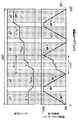
図5は第1実施形態の作動特性図で、アクチュエータ(サーボモータ)27の作動角の変化に対するエアミックスドア16の開度変化および吹出モードの変化を示す。この図5から分かるように、アクチュエータ27の作動角:360°(1回転)に対して、エアミックスドア16の開度を、0%(最大冷房位置)〜100%(最大暖房位置)との間で変化させる温度制御パターンを6回変化させるようになっている。但し、エアミックスドア16の開度:0%→100%→0%という山形の温度制御パターンを1つの単位として見れば、これを3回繰り返す制御パターンとなっている。
【0055】
このような温度制御パターンを実現するために、1つのループ状の溝形状からなる温度制御用係合溝30には、図4(b)に示すように分配リンク29の回転方向の3箇所に最大冷房位置MC1、MC2、MC3を設定し、この3箇所の最大冷房位置MC1、MC2、MC3の中間位置にそれぞれ(計3箇所の)最大暖房位置MH1、MH2、MH3を設定している。
【0056】
なお、本例では、最大冷房位置MC1、MC2、MC3は係合溝30のうち分配リンク29の回転中心Oから最も遠ざかる位置であり、逆に、最大暖房位置MH1、MH2、MH3は係合溝30のうち分配リンク29の回転中心Oに最も接近する位置である。これらの各位置は、図5下段の対応位置にも記入してある。
【0057】
図4(b)において、最大冷房位置MC2と最大暖房位置MH2との間が吹出モードを自動切替するオート領域Aである。係合溝30のオート領域Aにおいて、最大冷房位置MC2側から最大暖房位置MH2へ向かってフェイス用温度制御溝A1、アイドル溝A2、バイレベル用温度制御溝A3、アイドル溝A4、フット用温度制御溝A5が順次形成してある。
【0058】
アイドル溝A2、A4は、分配リンク29の回転中心Oを中心とする円弧状の溝部であって、分配リンク29の所定回転角の範囲にわたって形成してある。これにより、アイドル溝A2、A4の範囲ではエアミックスドア16の駆動を停止し、この間に吹出モードドア20、23、26を駆動することにより、オート領域Aにおいてエアミックスドア16と吹出モードドア20、23、26とを交互に駆動できるようにする。
【0059】
また、係合溝30の最大冷房位置MC3および最大暖房位置MH1、MH3も分配リンク29の回転中心Oを中心とする円弧状の溝部であって、分配リンク29の所定回転角の範囲にわたって形成してある。従って、これらの溝部範囲においてもエアミックスドア16の駆動を停止し、吹出モードドア20、23、26を駆動することにより、この両者の交互駆動が可能となる。
【0060】
なお、図5において、細点部はエアミックスドア16の駆動域(吹出モードドア20、23、26の停止域)を示し、白抜き部は、吹出モードドア20、23、26の駆動域(エアミックスドア16の停止域)を示す。
【0061】
一方、分配リンク29の吹出モード切替用係合溝31は、温度制御用係合溝30の温度制御パターンの変化に対応して溝形状が設定してある。但し、この2つの係合溝30、31に嵌合するピン33、38は、図3に例示するように、分配リンク29の回転中心Oに対して150°程度ずれた位置に配置してあるので、分配リンク29の回転方向において150°程度ずれた位置が表裏両面の係合溝30、31の対応位置となる。
【0062】
具体的には、吹出モード切替用係合溝31において、係合溝30の最大冷房位置MC1と最大暖房位置MH1との間に対応してバイレベル用溝部31aを設定し、係合溝30の最大暖房位置MH1と最大冷房位置MC2との間に対応してフェイス用溝部31bを設定し、係合溝30の最大冷房位置MC2と最大暖房位置MH2との間に対応してオート設定用溝部31cを設定している。
【0063】
更に、吹出モード切替用係合溝31において、係合溝30の最大暖房位置MH2と最大冷房位置MC3との間に対応してフット用溝部31dを設定し、係合溝30の最大冷房位置MC3と最大暖房位置MH3との間に対応してフットデフロスタ用溝部31eを設定し、係合溝30の最大暖房位置MH3と最大冷房位置MC1との間に対応してデフロスタ用溝部31fを設定している。
【0064】
上記オート設定用溝部31cでは、フェイス用溝部31bに連続してオート域フェイス用溝部31gを形成し、フット用溝部31dに連続してオート域フット用溝部31iを形成し、これらの中間部にオート域バイレベル用溝部31hを形成している。
【0065】
吹出モード切替用係合溝31において、上記各溝部31a〜31iは、すべて分配リンク29の回転中心Oを中心とする円弧形状になっているので、ピン38が上記各溝部31a〜31iの範囲に位置している間はピン38が変位しない。従って、この間は吹出モードリンク41が回転しないので、所定の吹出モードが保持、固定される。そして、上記各溝部31a〜31i相互の間にピン38を変位させる駆動溝部(符号の図示省略)を形成し、この駆動溝部の部位にて吹出モードリンク41を回転させて吹出モードの切替を行う。
【0066】
図5に例示するように、アクチュエータ27(分配リンク29)の360°の作動角のうち、マニュアル設定される各吹出モードのための作動角はそれぞれ40°で、合計200°であり、また、吹出モードのオート設定のための作動角は120°であり、残りの40°はマニュアル設定の吹出モード切替のための作動角である。
【0067】
図6は第1実施形態の空調操作パネル50の具体例であり、吹出モードノブ51は回転式の吹出モード操作部材であり、吹出モードをエアミックスドア16の開度変化に連動して自動切替するオート(Auto)位置の他に、フェイス(Face)モード位置、バイレベル(B/L)モード位置、フット(Foot)モード位置、フットデフロスタ(F/D)モード位置、及びデフロスタ(Def)モード位置に回転操作可能になっている。
【0068】
空調操作パネル50には、吹出モードノブ51の他に、回転式ノブを持つ温度設定器52、押しボタン式のエアコンスイッチ53、押しボタン式の内外気スイッチ54、回転式ノブを持つ送風スイッチ55等が設けられている。周知のごとく温度設定器52は温度設定信号、エアコンスイッチ53は空調用圧縮機(図示せず)の作動の断続信号、内外気スイッチ54は送風機ユニットの内気・外気の切替導入信号、送風スイッチ55は送風機ユニットの風量切替信号をそれぞれ発生する。
【0069】
なお、吹出モードノブ51は回転式操作部材に限らず、図7に示すように、案内溝56に沿ってスライド操作されるレバー状操作部材で構成してもよい。
【0070】
次に、第1実施形態における電気制御部の概要を図8により説明すると、空調用電子制御装置60には、空調制御のために、内気温TR、外気温TAM、日射量TS、蒸発器吹出温度(蒸発器冷却度合)TE、温水温度TW等を検出する周知のセンサ群61から検出信号が入力される。
【0071】
また、空調操作パネル50の吹出モードノブ51の操作位置信号、温度設定器52から車室内の設定温度信号Tset、エアコンスイッチ53から空調用冷凍サイクルの圧縮機作動の断続信号(ON,OFF信号)、内外気スイッチ54から内外気切替信号、および送風スイッチ55から送風機の風量切替信号が入力される。
【0072】
また、アクチュエータ27の回転位置センサ(ポテンショメータ)62からアクチュエータ27の作動角信号が入力される。
【0073】
空調用電子制御装置60はCPU、ROM、RAM等からなる周知のマイクロコンピュータと、その周辺回路にて構成されるもので、予め設定されたプログラムに従って所定の演算処理を行って、前述のアクチュエータ27、内外気切替ドア(図示せず)の駆動用アクチュエータ(サーボモータ)63、送風機(図示せず)の駆動用モータ64、圧縮機作動断続用の電磁クラッチ65等の通電制御を行うようになっている。
【0074】
次に、上記構成において本実施形態の作動を説明する。図9のフローチャートは空調用電子制御装置60のマイクロコンピュータにより実行される制御処理の概要を示し、図9の制御ルーチンは、車両エンジンのイグニッションスイッチがオンされて制御装置60に電源が供給された状態において、空調操作パネル50の送風スイッチ55が投入されるとスタートする。
【0075】
先ず、ステップS100ではフラグ、タイマー等の初期化がなされ、次のステップS110で、センサ群61からの検出信号、空調操作パネル50からの操作信号等を読み込む。
【0076】
続いて、ステップS120にて、下記数式1に基づいて、車室内へ吹き出される空調風の目標吹出温度(TAO)を算出する。この目標吹出温度(TAO)は車室内を温度設定器52の設定温度Tset に維持するために必要な吹出温度である。
【0077】
【数1】
TAO=Kset ×Tset −Kr ×TR−Kam×TAM−Ks ×TS+C
但し、TR:内気温、TAM:外気温、TS:日射量、Tset:設定温度信号
Kset 、Kr 、Kam、Ks :制御ゲイン
C :補正用の定数
次に、ステップS130に進み、エアミックスドア16の目標開度SWを次の数式2により算出する。
【0078】
【数2】
SW={(TAO−TE)/(TW−TE)}×100(%)
数式2によると、目標開度SWは、ヒータコア13の通風路を全閉する最大冷房位置を0%とし、冷風バイパス通路15を全閉する最大暖房位置を100%とする百分率で算出される。
【0079】
次に、ステップS140にてアクチュエータ27の目標作動角θを算出する。この目標作動角θは、図5の下段に示す特性を予めマップとしてROMに記憶しておくことにより、上記のエアミックスドア目標開度SWと吹出モードノブ51の操作位置信号とにより算出できる。すなわち、吹出モードノブ51の操作位置信号により乗員の選択した吹出モードが図5においてオート域を含む6つの吹出モードのどこに位置するかという情報と上記のエアミックスドア目標開度SWの情報とにより、図5横軸のアクチュエータ目標作動角θを決定できる。
【0080】
次に、ステップS150にて送風機ユニットの送風ファンにより送風される空気の目標送風量BLWを上記TAOに基づいて算出する。この目標送風量BLWの算出方法は周知であり、上記TAOの高温側(最大暖房側)および低温側(最大冷房側)で目標風量を大きくし、上記TAOの中間温度域で目標風量を小さくする。
【0081】
次に、ステップS160にて上記TAOに応じて内外気モードを決定する。この内外気モードは周知のごとくTAOが低温側から高温側へ上昇するにつれて、内気モード→外気モードと切替設定するか、あるいは全内気モード→内外気混入モード→全外気モードと切替設定する。
【0082】
次に、ステップS170にて圧縮機のON−OFFを決定する。具体的には、上記TAOと外気温TAMに基づいて目標蒸発器吹出温度TEOを算出し、実際の蒸発器吹出温度TEと目標蒸発器吹出温度TEOとを比較して、TE>TEOのときは圧縮機ONとし、TE≦TEOのときは圧縮機OFFとする。
【0083】
次に、ステップS180にて上記各ステップS140〜S170で演算された各種制御値をアクチュエータ27、63、送風機モータ64、および電磁クラッチ65に出力して空調制御を行う。
【0084】
すなわち、アクチュエータ27は、位置検出センサ62により検出される実際の作動角がステップS140の目標作動角θと一致するように制御される。より具体的には、アクチュエータ27の実際の作動角が目標作動角θと一致していないときは制御装置60によりアクチュエータ27へ電源が供給され、アクチュエータ27が作動する。
【0085】
ここで、アクチュエータ27のモータへの電源供給の正負の極性を切り替えることにより、アクチュエータ27を正逆両方向に回転させることができる。そして、アクチュエータ27の作動により実際の作動角が目標作動角θと一致すると、制御装置60によりアクチュエータ27への電源供給が停止され、アクチュエータ27が停止する。
【0086】
また、送風機モータ64はステップS150の目標風量BLWが得られるように印加電圧が制御されて回転数が制御される。また、内外気用モータ63はステップS160の内外気モードが得られるように内外気ドア(図示せず)の操作位置を制御する。電磁クラッチ65は実際の蒸発器吹出温度TEが目標蒸発器吹出温度TEOとなるように圧縮機作動をON−OFF制御する。
【0087】
次に、第1実施形態による特徴点について述べると、
▲1▼エアミックスドア16と吹出モードドア20、23、26を1つのアクチュエータ27により駆動するから、アクチュエータ数の低減とそれに伴う空調用電子制御装置60の回路構成の簡素化等により大幅なコスト低減を達成できる。しかも、アクチュエータの共用化を行うにもかかわらず、空調機能を次のように良好に発揮できる。
【0088】
▲2▼吹出モードノブ51の操作位置を選択することにより、図5に示すようにフェイスモード、バイレベルモード、フットモード、フットデフロスタモード、及びデフロスタモードの各吹出モードを乗員の意志に従って自由にマニュアル設定できる。
【0089】
▲3▼この各吹出モードをマニュアル設定する際に、温度設定器52を所望の設定温度Tsetに設定して目標作動角θを変更することにより、エアミックスドア16の開度を最大冷房位置(開度:0%)と最大暖房位置(開度:100%)の間で変化させることができる。従って、各吹出モードを固定したまま、各吹出モードでの吹出温度をエアミックスドア16により制御可能な全範囲にて制御することができる。
【0090】
▲4▼吹出モードノブ51をオート位置に操作すると、目標作動角θが図5の最大冷房位置MC2と最大暖房位置MH2との間となり、エアミックスドア16の開度変化に連動して、フェイスモードとバイレベルモードとフットモードを自動切替することができる。従って、乗員は吹出モード設定のためのマニュアル操作が不要となり、乗員の操作負担を軽減できる。なお、フットデフロスタモード及びデフロスタモードは窓ガラスの曇り除去のためにエアミックスドア開度と無関係に設定するものであるから、エアミックスドア開度変化に連動して自動設定することはしない。
【0091】
▲5▼エアミックスドア16の開度変化と吹出モードの自動切替とを連動させるオートモード域を図5のごとくマニュアル設定する他の複数の吹出モードの中間部に配置しているから、吹出モードノブ51をオート位置から別の吹出モード位置に操作して、吹出モードをオート設定のモードから別の吹出モードにマニュアル設定する際に、オートモード域からその特定の吹出モードに切り替えるに必要なアクチュエータ作動角を減少できる。
【0092】
つまり、オートモード域を図5上段の吹出モード部の左右の端部に配置した場合は、左右の一端部のオートモード域から他端部の特定の吹出モードに切り替える場合が生じると、アクチュエータ作動角を360°近傍の大きな角度変化させる必要があり、吹出モード切替の時間が長くなる。また、この間、アクチュエータ作動角の変化に連動してエアミックスドア開度が図5下段の特性に従って何回も増減して、車室内への吹出温度が上下動するので、乗員に違和感を与える。
【0093】
しかし、上記のようにオートモード域を他の複数の吹出モードの中間部に配置することにより、上記不具合を最小限に抑制できる。
【0094】
▲6▼アクチュエータ作動角の変化に対して、エアミックスドア16の開度変化の区間(図5の作動特性の細点部)と、吹出モード切替の区間(図5の作動特性の白抜き部)とを交互に設定して、エアミックスドア16と吹出モードドア20、23、26とを交互に駆動するようにしているから、アクチュエータ27の必要駆動トルクを減少でき、アクチュエータ27を小型化、低コスト化できる。
【0095】
(第2実施形態)
第1実施形態では、アクチュエータ27により回転駆動される1つの分配リンク29の表裏両面に、温度制御用係合溝30と吹出モード切替用係合溝31を設けて、エアミックスドア16と吹出モードドア20、23、26とを駆動する駆動システムとしているが、第2実施形態では、上記分配リンク29の役割を2つのリンクに分割する構成としている。
【0096】
第2実施形態では、図10に示すように、サーボモータからなるアクチュエータ27の出力軸28に減速用ギヤ70および温度制御用(エアミックス用)リンク71を一体に設けている。
【0097】
温度制御用リンク71は、図11に示すように概略円板状の部材であって、その裏面側に1つのループ状の温度制御用係合溝72が設けてある。この係合溝72には第1実施形態と同様に接続レバー32に一体に設けたピン33が摺動可能に嵌合している。従って、ピン33の変位により、接続レバー32、接続ロッド35およびエアミックスドアレバー36を介してエアミックスドア16が回転軸16aを中心として回転する。
【0098】
ループ状の温度制御用係合溝72には、図11に示すように溝形状パターンの異なる2つの係合溝72a、72aが設けてある。この2つの係合溝72a、72aは、リンク71の回転中心Oを通る中心線Lに対してそれぞれ片側の180°の区間に構成してある。
【0099】
そして、本例では、温度制御用係合溝72(係合溝72a、72a)のうち中心線Lの一端側に最大冷房位置MCを設定し、他端側に最大暖房位置MHを設定している。最大冷房位置MCは係合溝72のうちリンク71の回転中心Oから最も遠ざかる位置であり、逆に、最大暖房位置MHは係合溝72のうちリンク71の回転中心Oに最も接近する位置である。これらの各位置は、図12下段の対応位置にも記入してある。
【0100】
図11において、中心線Lの上方側に位置する一方の係合溝72aは第1実施形態の温度制御用係合溝30のオート域Aに対応する溝部であり、一方の係合溝72aにおいて、最大冷房位置MC側から最大暖房位置MH側へ向かってフェイス用温度制御溝A1、アイドル溝A2、バイレベル用温度制御溝A3、アイドル溝A4、フット用温度制御溝A5が順次形成してある。
【0101】
アイドル溝A2、A4は、リンク71の所定作動角の範囲にわたって回転中心Oを中心とする円弧状に形成することにより、アイドル溝A2、A4の範囲では係合溝72が回転変位してもピン33の位置が一定に維持される。これにより、エアミックスドア16の駆動を停止し、この間に吹出モードドア20、23、26を駆動することができる。従って、一方の係合溝72aによるオート領域においてエアミックスドア16と吹出モードドア20、23、26とを交互に駆動できる。
【0102】
他方の係合溝72bは温度制御用リンク71の180°の作動角変化に対してエアミックスドア16の開度を連続的に変化させるものであるため、最大暖房位置MH側から最大冷房位置MC側へ向かって、回転中心Oからの径方向寸法が連続的に増加するようになっている。このため、他方の係合溝72bはアイドル溝の区間を具備していない。
【0103】
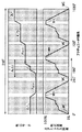
図12の下段に示す温度制御パターンにおいて、最大冷房位置MC側から最大暖房位置MH側へ向かう上向きの特性が一方の係合溝72aによるもので、最大暖房位置MH側から最大冷房位置MC側へ向かう下向きの特性が他方の係合溝72bによるものである。
【0104】
アクチュエータ27の出力軸28の減速用ギヤ70には、吹出モード切替リンク73をギヤ結合している。本例では、図13に示すように吹出モード切替リンク73の外周面に減速用ギヤ70とかみ合うギヤ部73aを直接形成している。ギヤ部73aの直径が減速用ギヤ70より十分大きいため、アクチュエータ27の回転が減速して吹出モード切替リンク73に伝達される。
【0105】
具体的一例として、アクチュエータ27(温度制御用リンク71)の作動角(1080°=3回転)に対して、吹出モード切替リンク73が360°回転するようにしてある。このような減速機構の介在により、吹出モード切替リンク73の作動角を必要作動角まで低減できる。
【0106】
吹出モード切替リンク73は回転軸75により空調ケース11に回転可能に支持されており、吹出モード切替リンク73には図13に示すように吹出モード切替用係合溝31が設けてある。この係合溝31は第1実施形態の係合溝31と同一形状であり、吹出モード切替用係合溝31の中間部にオート設定用溝部31cを設定し、このオート設定用溝部31cの前後両側にバイレベル用溝部31a、フェイス用溝部31b、フット用溝部31d、フットデフロスタ用溝部31e、およびデフロスタ用溝部31fを設定している。上記オート設定用溝部31cでは、オート域フェイス用溝部31g、オート域バイレベル用溝部31h、およびオート域フット用溝部31iを形成している。
【0107】
吹出モード切替用係合溝31には第1実施形態と同様に接続レバー37のピン38が摺動可能に嵌合し、接続レバー37は接続ロッド40を介して吹出モードリンク41に連結されている。そして、吹出モードリンク41の回転により吹出モードドア20、23、26を開閉駆動する。これらの部材は基本的には第1実施形態の図3と同じでよいので、詳細説明は省略する。
【0108】
なお、吹出モード切替用係合溝31において、上記各溝部31a〜31iは、第1実施形態と同様にすべて分配リンク73の回転中心Oを中心とする同心円の円弧形状になっているので、ピン38が上記各溝部31a〜31iの範囲に位置している間はピン38が変位しない。従って、この間は吹出モードリンク41が回転しないので、所定の吹出モードが保持、固定される。そして、上記各溝部31a〜31i相互の間にピン38を変位させる駆動溝部(符号の図示省略)を形成し、この駆動溝部の部位にて吹出モードリンク41を回転させて吹出モードの切替を行う。
【0109】
次に、第2実施形態の特徴を説明すると、第2実施形態では、アクチュエータ27の出力軸28に温度制御用リンク71を直結するとともに、アクチュエータ27の出力軸28に吹出モード切替リンク73をギヤ結合して、アクチュエータ27の回転を減速(本例では1/3に減速)してリンク73に伝達するように構成している。
【0110】
このため、第2実施形態では、図12に示すように、アクチュエータ27(温度制御用リンク71)が1080°回転(3回転)する間に吹出モード切替リンク73が1回転して、第1実施形態の図5と同じ作動特性(温度制御及び吹出モード切替)を発揮する。
【0111】
第2実施形態によると、温度制御用リンク71が多回転する構成であるため、図11に示すように、ループ状の温度制御用係合溝72において、最大冷房位置MCと最大暖房位置MHとの間に180°の区間を設けることができる。このことから、アクチュエータ27の作動角とエアミックス開度との比(エアミックス開度/アクチュエータ27の作動角)を小さくでき、アクチュエとータ27の作動角による温度制御の分解能を高めることができる。
【0112】
因みに、第1実施形態では図5に示すようにアクチュエータ27(分配リンク29)の作動角(360°)の範囲内に図5に示すように6つの温度制御パターンを設定するため、例えば、オート域で120°の作動角を割り当てると、他の5つの吹出モード域では割り当て可能な作動角が40°程度の小さな角度になってしまう。その結果、アクチュエータ27の作動角とエアミックス開度との比(エアミックス開度/アクチュエータ27の作動角)が大きくなり、温度制御の分解能が低下するので、温度制御性悪化の原因となる。しかし、第2実施形態によると、温度制御の分解能を高めて、吹出空気の温度制御性を第1実施形態より向上できる。
【0113】
但し、第2実施形態ではアクチュエータ27(温度制御用リンク71)の作動角の増加(360°→1080°)により、吹出モード切替時の切替時間が第1実施形態より長くなるという不利な点がある。従って、第2実施形態においても、前述の作用効果▲5▼を除く他の作用効果▲1▼〜▲4▼、▲6▼は第1実施形態と同様に発揮できる。
【0114】
(他の実施形態)
なお、上述の実施形態では、車室内への吹出空気温度を制御する温度制御手段として、冷風バイパス通路15を通過する冷風とヒータコア13を通過する温風との風量割合を調整するエアミックスドア16を用いているが、ヒータコア13を通過する温水流量を調整する温水弁等を温度制御手段として用いてもよい。
【0115】
また、上述の実施形態では、吹出モードドアとして3枚の板状のドア20、23、26を用いる場合について説明したが、公知の半円筒状のロータリドア、あるいは可撓性のある樹脂フィルム部材から構成されるフィルムドア等を吹出モードドアとして用いれば、吹出モードドアを1つの一体ドア部品で構成できる。
【図面の簡単な説明】
【図1】本発明の第1実施形態の車両用空調装置の要部の概略断面図である。
【図2】第1実施形態で用いるドア駆動システムのリンク機構の概略構成図である。
【図3】第1実施形態で用いるドア駆動システムの空調ユニット部への搭載図である。
【図4】第1実施形態で用いるドア駆動システムの分配リンクの説明図である。
【図5】第1実施形態の作動特性の説明図である。
【図6】第1実施形態で用いる空調操作パネルの一例の正面図である。
【図7】第1実施形態で用いる空調操作パネルの他の例の正面図である。
【図8】第1実施形態の電気制御ブロック図である。
【図9】第1実施形態の空調制御の概略を示すフローチャートである。
【図10】第2実施形態で用いるドア駆動システムのリンク機構の概略構成図である。
【図11】第2実施形態で用いるドア駆動システムの温度制御リンクの正面図である。
【図12】第2実施形態の作動特性の説明図である。
【図13】第2実施形態で用いるドア駆動システムの吹出モード切替リンクの正面図である。
【符号の説明】
16…エアミックスドア(温度制御手段)、19、22、24…開口部、
20、23、26…吹出モードドア、27…アクチュエータ、
29…分配リンク、30、72…温度制御用係合溝、
31…吹出モード切替用係合溝。[0001]
BACKGROUND OF THE INVENTION
The present invention relates to a drive system for a blowout mode door and temperature control means (air mix door, hot water valve, etc.) in a vehicle air conditioner.
[0002]
[Prior art]
Conventionally, a vehicle air conditioner is provided with an inside / outside air switching door, a temperature control means (air mix door, hot water valve, etc.), and a blow mode door, and these devices are operated by a manual operation mechanism or an actuator (servo motor). Each is operated independently.
[0003]
[Problems to be solved by the invention]
In recent years, an increasing number of vehicle air conditioners have been provided that allow the above-mentioned devices to be operated lightly by actuating an actuator by a switch operation in order to improve operability by passengers. In such a case, a dedicated actuator is required for each of the inside / outside air switching, temperature control, and blowing mode switching, resulting in an increase in cost.
[0004]
In view of this, the present inventors have studied to perform temperature control and blowing mode switching with a single actuator in order to reduce the number of actuators. That is, paying attention to the fact that the switching of the blowing mode has a correlation with the operation position of the temperature control means, the blowing mode is changed to the face mode and the bi-level mode as the operation position of the temperature control means shifts from the low temperature side to the high temperature side. Then, it was examined that the temperature control and the switching of the blowing mode are performed by one actuator by sequentially switching to the foot mode.
[0005]
However, if the temperature control and the switching of the blowing mode are simply performed by one actuator, the operation position of the temperature control means and the switching of the blowing mode are always fixed in a one-to-one relationship. As a result, the following problems occur.
[0006]
That is, the first is that the temperature control range in each blowing mode is always fixed to a predetermined temperature range. In other words, the face mode is fixed to the low temperature range, the bilevel mode is fixed to the intermediate temperature range, and the foot mode is fixed to the high temperature range. Cannot be set, and the selection range of the air conditioning state is narrowed.
[0007]
In addition, the defroster mode needs to be set as needed when the window glass is fogged regardless of the operation position of the temperature control means. However, as described above, the temperature control and the switching of the blowing mode are simply linked. And defroster mode cannot be set at any time.
[0008]
The present invention has been made in view of the above points. The temperature control means and the blow mode door can be driven by one actuator, and the temperature control in each blow mode is performed at the lowest level of the temperature control means. It aims at providing the vehicle air conditioner which can be performed over the whole range from the temperature side to the highest temperature side.
[0009]
Further, the present invention provides an auto air conditioner that automatically switches between a plurality of blowing modes in conjunction with the operation position of the temperature control means in a vehicle air conditioner that drives the temperature control means and the blow mode door with a single actuator. The purpose is to achieve both a mode function and a manual mode function in which a plurality of blowing modes can be manually set at any time by an occupant's operation.
[0010]
[Means for Solving the Problems]
The present invention has been devised in order to achieve the above object. In the invention according to claim 1, temperature control means (16) for controlling the temperature of the air blown into the passenger compartment and a plurality of parts in the passenger compartment are provided. A plurality of openings (19, 22, 24) for blowing air and a plurality of openings (19, 22, 24) are opened and closed, and a blowing mode door (20 for switching the blowing mode into the vehicle interior to a plurality of blowing modes) , 23, 26) and one actuator (27) for driving the temperature control means (16) and the blowing mode door (20, 23, 26),
For each predetermined operating angle range of the actuator (27), a temperature control pattern for changing the position of the temperature control means (16) between the lowest temperature position and the highest temperature position appears periodically a plurality of times. And
The blow mode door (20, 23, 26) is driven to a predetermined blow mode position corresponding to each temperature control pattern.And
Among the temperature control patterns of a plurality of times, in one temperature control pattern, as the position of the temperature control means (16) changes between the lowest temperature position and the highest temperature position, the blowing mode door (20, 23, 26). ) To open and close a plurality of openings (19, 22, 24) to automatically switch between a plurality of blowing modes,
Furthermore, even if the position of the temperature control means (16) changes between the lowest temperature position and the highest temperature position in the other plurality of temperature control patterns among the plurality of temperature control patterns, the blowing mode door (20, 23, 26) are fixed at different blowing mode positions.It is characterized by that.
[0011]
Thereby, switching of the blowing temperature control and blowing mode in a vehicle air conditioner can be performed by one actuator (27).
[0012]
In addition, a temperature control pattern for changing the position of the temperature control means (16) between the lowest temperature position and the highest temperature position for each of the plurality of blowing modes is applied to control the temperature control in each blowing mode. Can be performed over the entire range from the lowest temperature side to the highest temperature side.
[0013]
In addition, multiple blowing modesofFor example, by setting the defroster mode in advance, the defroster mode can be set as needed when the window glass is fogged.
[0015]
According to the first aspect of the present invention, as the position of the temperature control means (16) changes between the lowest temperature position and the highest temperature position in one temperature control pattern among a plurality of temperature control patterns. Since the plurality of openings (19, 22, 24) are opened and closed by the blowing mode door (20, 23, 26), the plurality of blowing modes are automatically switched.In the one temperature control pattern, an auto mode function of automatically switching a plurality of blowing modes in conjunction with the operation position of the temperature control means (16) can be exhibited, and the operation burden of the occupant's blowing mode switching can be reduced.
[0016]
Moreover,According to the first aspect of the present invention, even if the position of the temperature control means (16) changes between the lowest temperature position and the highest temperature position in a plurality of other temperature control patterns among the plurality of temperature control patterns. Because the blowout mode doors (20, 23, 26) are fixed at different blowout mode positions,In the other plural temperature control patterns, a manual mode function capable of manually setting a plurality of blowing modes at any time by an occupant's operation can be exhibited. Therefore, based on the occupant's will, the desired temperature mode is desired regardless of the blowing temperature range. The blowout mode can be set manually. Further, in the desired blowing mode set manually, the blowing air temperature can be controlled over the entire range of the lowest temperature position and the highest temperature position of the temperature control means (16).
[0017]
Claim2In the invention described inTemperature control means (16) for controlling the temperature of the air blown into the passenger compartment, a plurality of openings (19, 22, 24) for blowing air to a plurality of parts in the passenger compartment, and a plurality of openings (19, 22, 24) ) Is opened and closed, and the blow mode door (20, 23, 26) for switching the blow mode into the vehicle interior to a plurality of blow modes, the temperature control means (16), and the blow mode door (20, 23, 26) are driven. One actuator (27) toDistributing link (29) that rotates in response to operating force of actuator (27)WhenWith
For each predetermined operating angle range of the actuator (27), a temperature control pattern for changing the position of the temperature control means (16) between the lowest temperature position and the highest temperature position appears periodically a plurality of times. And
A temperature control engagement groove (30) for changing the position of the temperature control means (16) by causing the temperature control pattern to appear periodically a plurality of times on one side of the front and back surfaces of the distribution link (29). Providing a blowout mode switching engagement groove (31) on the other surface side of the distribution link (29),
According to the rotational displacement of the blowout mode switching engagement groove (31)In response to multiple temperature control patterns,Drive the blowout mode door (20, 23, 26) to the specified blowout mode positionAnd
Further, the blow mode switching engagement groove (31) has an automatic setting groove portion that automatically switches between a plurality of blow modes in accordance with a change in position of the temperature control means (16) in a predetermined operating angle range of the distribution link (29). Regardless of the change in position of the temperature control means (16) in the other predetermined operating angle range of (31c) and the distribution link (29), the blowing mode doors (20, 23, 26) are set to different blowing mode positions. Manual setting groove portions (31a, 31b, 31d to 31f) to be fixedIt is characterized by that.
[0018]
As a result, the temperature control engagement groove (30) and the blowing mode switching engagement groove (31) are provided on the front and back surfaces of one distribution link (29).The blow mode switching engagement groove (31) is provided with an auto setting groove (31c) and manual setting grooves (31a, 31b, 31d to 31f), so that a plurality of blow modes can be controlled by the temperature control means ( The automatic mode function that automatically switches in conjunction with the operation position of 16) and the manual mode function that allows manual setting of a plurality of blowing modes at any time by the occupant's operation can be exhibited.
Therefore, in the invention described in
[0021]
Claim3In the invention described inTemperature control means (16) for controlling the temperature of the air blown into the passenger compartment, a plurality of openings (19, 22, 24) for blowing air to a plurality of parts in the passenger compartment, and a plurality of openings (19, 22, 24) ) Is opened and closed, and the blow mode door (20, 23, 26) for switching the blow mode into the vehicle interior to a plurality of blow modes, the temperature control means (16), and the blow mode door (20, 23, 26) are driven. One actuator (27) for
Furthermore,A first position adjustment mechanism (71, 33, 32, 35, 36) for adjusting the position of the temperature control means (16) in response to the rotation of the actuator (27), and a blowout in response to the rotation of the actuator (27) A second position adjustment mechanism (73, 38, 37, 40, 41) for adjusting the position of the mode door (20, 23, 26) is provided in parallel.
For each predetermined operating angle range of the actuator (27),By the first position adjustment mechanismThe position of the temperature control means (16) is changed between the lowest temperature position and the highest temperature position.Make the temperature control pattern appear multiple times periodicallyIt is supposed to
While corresponding to multiple temperature control patterns respectivelyIn conjunction with the appearance of multiple temperature control patterns, the second position adjustment mechanism drives the blowing mode door (20, 23, 26) to a predetermined blowing mode position.And
The first position adjustment mechanism has a temperature control link (71) that rotates in response to the operation force of the actuator (27),
The temperature control link (71) is provided with a loop-shaped temperature control engagement groove (72) having a groove shape corresponding to the temperature control pattern.It is characterized by that.
[0022]
according to this,Similarly to the first and second aspects of the invention, the blowout temperature control and the blowout mode switching in the vehicle air conditioner can be performed by one actuator (27), and the temperature control in each blowout mode is performed at the temperature. It can be performed over the entire range from the lowest temperature side to the highest temperature side of the control means. Further, by setting the defroster mode in advance as one of the plurality of blowing modes, the defroster mode can be set as needed when the window glass is fogged.
Furthermore, in the invention according to claim 3,Since the first position adjustment mechanism for the temperature control means and the second position adjustment mechanism for the blow-out mode door operate in parallel in response to the rotation of the actuator (27), the temperature control means for the operating angle of the actuator (27) And the displacement amount of the blowing mode door (20, 23, 26) with respect to the operating angle of the actuator (27) can be set independently. Therefore, in the first position adjustment mechanism, by reducing the ratio of the displacement amount of the temperature control means to the operating angle of the actuator (27), it is possible to improve the temperature control resolution and improve the temperature controllability of the blowing temperature.
[0024]
Claim4Invention described inThen, temperature control means (16) for controlling the temperature of the air blown into the vehicle interior, a plurality of openings (19, 22, 24) for blowing air to a plurality of parts in the vehicle interior, and a plurality of openings (19, 22) , 24) to open and close the blow mode door (20, 23, 26) for switching the blow mode to the vehicle interior to a plurality of blow modes, the temperature control means (16) and the blow mode door (20, 23, 26) One actuator (27) for driving
Further, a first position adjusting mechanism (71, 33, 32, 35, 36) for adjusting the position of the temperature control means (16) in response to the rotation of the actuator (27), and a response to the rotation of the actuator (27). And a second position adjustment mechanism (73, 38, 37, 40, 41) for adjusting the position of the blowing mode door (20, 23, 26) in parallel,
For each predetermined operating angle range of the actuator (27), a temperature control pattern for changing the position of the temperature control means (16) between the minimum temperature position and the maximum temperature position by the first position adjustment mechanism is periodically multiple times. It is supposed to appear,
Corresponding to a plurality of temperature control patterns and interlocking with the appearance of the plurality of temperature control patterns, the second mode adjustment mechanism drives the blowing mode door (20, 23, 26) to a predetermined blowing mode position.
The second position adjustment mechanism has a blowing mode switching link (73) that rotates in response to the operation force of the actuator (27),
The blow mode switching link (73) is provided with a blow mode switching engagement groove (31).
In the blow mode switching engagement groove (31), an auto setting groove portion for automatically switching a plurality of blow modes in accordance with a change in position of the temperature control means (16) in a predetermined operating angle range of the blow mode switching link (73). (31c) and the blowing mode switching link (73) in another predetermined operating angle range, regardless of the position change of the temperature control means (16), the blowing mode doors (20, 23, 26) are set in different blowing modes. Manual setting groove portions (31a, 31b, 31d to 31f) to be fixed in positionIt is characterized by that.
According to this, similarly to the first to third aspects of the invention, the blowout temperature control and the blowout mode switching in the vehicle air conditioner can be performed by one actuator (27), and in each blowout mode. The temperature control can be performed over the entire range from the lowest temperature side to the highest temperature side of the temperature control means. Further, by setting the defroster mode in advance as one of the plurality of blowing modes, the defroster mode can be set as needed when the window glass is fogged.
In addition, in the invention according to
Furthermore, in the invention according to
[0025]
Claim5In the invention described inTemperature control means (16) for controlling the temperature of the air blown into the passenger compartment, a plurality of openings (19, 22, 24) for blowing air to a plurality of parts in the passenger compartment, and a plurality of openings (19, 22, 24) ) Is opened and closed, and the blow mode door (20, 23, 26) for switching the blow mode into the vehicle interior to a plurality of blow modes, the temperature control means (16), and the blow mode door (20, 23, 26) are driven. One actuator (27) for
For each predetermined operating angle range of the actuator (27), a temperature control pattern for changing the position of the temperature control means (16) between the lowest temperature position and the highest temperature position appears periodically a plurality of times. And
The blow mode doors (20, 23, 26) are driven to predetermined blow mode positions corresponding to the temperature control patterns of a plurality of times,
The temperature control means (16) and the blowing mode door (20, 23, 26) are driven alternately.
[0026]
Thus, similarly to the first to fourth aspects of the invention, the blowout temperature control and the blowout mode switching in the vehicle air conditioner can be performed by one actuator (27), and the temperature in each blowout mode. Control can be performed over the entire range from the lowest temperature side to the highest temperature side of the temperature control means. Further, by setting the defroster mode in advance as one of the plurality of blowing modes, the defroster mode can be set as needed when the window glass is fogged.
In addition, in the invention described in claim 5, since the temperature control means (16) and the blowing mode door (20, 23, 26) are driven alternately, the temperature control means and the blowing mode door are driven simultaneously. Compared to the above, the required drive torque of the actuator (27) can be reduced, and the actuator (27) can be reduced in size and cost.
Claim6As in the invention described in claim 1,Or 5The vehicle air conditioner according to claim 1, comprising a distribution link (29) that rotates in response to an operating force of the actuator (27),
A temperature control engagement groove (30) for changing the position of the temperature control means (16) by causing the temperature control pattern to appear periodically a plurality of times on one side of the front and back surfaces of the distribution link (29). Provided,
A blowout mode switching engagement groove (31) is provided on the other surface side of the distribution link (29),
The blowing mode door (20, 23, 26) may be driven to a predetermined blowing mode position according to the rotational displacement of the blowing mode switching engagement groove (31).
Claim7As in the invention described in claim 1,Or 51, a first position adjustment mechanism (71, 33, 32, 35, 36) for adjusting the position of the temperature control means (16) in response to the rotation of the actuator (27), and an actuator ( 27) in parallel with a second position adjustment mechanism (73, 38, 37, 40, 41) that adjusts the position of the blowing mode door (20, 23, 26) in response to the rotation of
The temperature control pattern appears periodically multiple times by the first position adjustment mechanism,
In conjunction with the appearance of a plurality of temperature control patterns, the blowing mode door (20, 23, 26) may be driven to a predetermined blowing mode position by the second position adjustment mechanism.
[0027]
Claim8The vehicle air conditioner according to
[0028]
Thereby, when manually setting the blowing mode from the auto setting mode to another mode, the operating angle of the actuator (27) can be reduced to shorten the mode switching time.
[0029]
Claim9In the invention described in claim 1, the claims 1 to8In any one of the above, as a plurality of openings, a face opening (22) that blows air to the passenger head side in the vehicle interior, and a foot opening (24) that blows air to the passenger feet side in the vehicle interior, A defroster opening (19) for blowing air to the vehicle window glass side,
As a plurality of blowing modes automatically switched in one temperature control pattern, a face mode for blowing air from the face opening (22), a bi-level for blowing air from both the face opening (22) and the foot opening (24) Set the mode and the foot mode that blows air out of the foot opening (24),
In addition to the face mode, the bi-level mode, and the foot mode, at least a defroster mode for blowing air from the defroster opening (19) is set as a plurality of blowing modes that are respectively fixed in a plurality of other temperature control patterns. Features.
[0030]
Thereby, the face mode, the bi-level mode, and the foot mode can be automatically switched in the auto setting state of the blowing mode. In addition, when manually setting the blowing mode, at least the defroster mode can be set in addition to the face mode, the bi-level mode, and the foot mode.
[0031]
In addition, the code | symbol in the bracket | parenthesis of each said means shows the correspondence with the specific means as described in embodiment mentioned later.
[0032]
DETAILED DESCRIPTION OF THE INVENTION
(First embodiment)
FIG. 1 is a cross-sectional view schematically showing an outline of an air conditioning unit portion of a vehicle air conditioner according to the first embodiment. The air conditioner of this embodiment has a so-called semi-center layout, The air-
[0033]
A blower unit (not shown) that blows conditioned air to the
[0034]
The
[0035]
In the air passage in the
[0036]
A cold
[0037]
A
[0038]
A plurality of blowout openings are formed on the downstream side of the air passage of the
[0039]
Next, the
[0040]
Next, the
[0041]
In the example of FIG. 1, each of the
[0042]
In the
[0043]
Here, as the
[0044]
Next, the drive system of the
[0045]
FIG. 2 is a schematic configuration diagram of the drive system (mechanical mechanism unit) according to the first embodiment, and FIG. 3 shows a specific mounting example of the drive system on the outer surface (side surface on the driver's seat side) of the
[0046]
As shown in FIGS. 2 and 3, an
[0047]
As shown in FIG. 4B, the temperature
[0048]
The air
[0049]
Here, the
[0050]
The blowout mode switching
[0051]
Further, the
[0052]
The
[0053]
A
[0054]
FIG. 5 is an operation characteristic diagram of the first embodiment, showing changes in the opening of the
[0055]
In order to realize such a temperature control pattern, the temperature
[0056]
In this example, the maximum cooling positions MC1, MC2, and MC3 are positions farthest from the rotation center O of the
[0057]
In FIG.4 (b), between the largest cooling position MC2 and the largest heating position MH2 is the auto area | region A which switches the blowing mode automatically. In the auto region A of the
[0058]
The idle grooves A <b> 2 and A <b> 4 are arc-shaped grooves centering on the rotation center O of the
[0059]
Further, the maximum cooling position MC3 and the maximum heating positions MH1 and MH3 of the
[0060]
In FIG. 5, the thin dot portion indicates the drive range of the air mix door 16 (stop region of the blowing
[0061]
On the other hand, the blowing mode switching
[0062]
Specifically, in the blowout mode switching
[0063]
Further, in the blowout mode switching
[0064]
In the auto setting
[0065]
In the blowout mode switching
[0066]
As illustrated in FIG. 5, among the 360 ° operating angles of the actuator 27 (distribution link 29), the operating angles for each manually set blowing mode are 40 °, which is a total of 200 °, The operating angle for auto setting of the blowing mode is 120 °, and the remaining 40 ° is the operating angle for switching the manually setting blowing mode.
[0067]
FIG. 6 is a specific example of the air
[0068]
In addition to the
[0069]
The blow-out
[0070]
Next, the outline of the electric control unit in the first embodiment will be described with reference to FIG. 8. The air conditioning
[0071]
Further, the operation position signal of the
[0072]
Further, an operating angle signal of the
[0073]
The air-conditioning
[0074]
Next, the operation of this embodiment in the above configuration will be described. The flowchart of FIG. 9 shows an outline of the control processing executed by the microcomputer of the air conditioning
[0075]
First, in step S100, flags, timers, and the like are initialized, and in the next step S110, detection signals from the
[0076]
Subsequently, in step S120, based on the following formula 1, a target blowing temperature (TAO) of the conditioned air blown into the passenger compartment is calculated. This target blowing temperature (TAO) is a blowing temperature necessary for maintaining the passenger compartment at the set temperature Tset of the
[0077]
[Expression 1]
TAO = Kset * Tset-Kr * TR-Kam * TAM-Ks * TS + C
However, TR: inside temperature, TAM: outside temperature, TS: solar radiation, Tset: set temperature signal
Kset, Kr, Kam, Ks: Control gain
C: Correction constant
Next, it progresses to step S130 and the target opening degree SW of the
[0078]
[Expression 2]
SW = {(TAO-TE) / (TW-TE)} × 100 (%)
According to
[0079]
Next, the target operating angle θ of the
[0080]
Next, in step S150, a target air blowing amount BLW of air blown by the blower fan of the blower unit is calculated based on the TAO. The calculation method of the target air flow amount BLW is well known. The target air volume is increased on the high temperature side (maximum heating side) and the low temperature side (maximum cooling side) of the TAO, and the target air volume is decreased in the intermediate temperature range of the TAO. .
[0081]
Next, in step S160, the inside / outside air mode is determined in accordance with the TAO. As is well known, the inside / outside air mode is switched from the inside air mode to the outside air mode or the whole inside air mode → the inside / outside air mixing mode → all the outside air mode as the TAO increases from the low temperature side to the high temperature side.
[0082]
Next, in step S170, ON / OFF of the compressor is determined. Specifically, the target evaporator outlet temperature TEO is calculated based on the TAO and the outside air temperature TAM, and the actual evaporator outlet temperature TE and the target evaporator outlet temperature TEO are compared. When TE> TEO, The compressor is turned on, and when TE ≦ TEO, the compressor is turned off.
[0083]
Next, in step S180, the various control values calculated in steps S140 to S170 are output to the
[0084]
That is, the
[0085]
Here, by switching the positive / negative polarity of the power supply to the motor of the
[0086]
Further, the rotation speed of the
[0087]
Next, the feature points according to the first embodiment will be described.
(1) Since the
[0088]
(2) By selecting the operation position of the
[0089]
(3) When manually setting each blowing mode, the
[0090]
(4) When the
[0091]
(5) Since the auto mode region that links the opening change of the
[0092]
In other words, when the auto mode area is arranged at the left and right ends of the blowing mode section in the upper part of FIG. 5, when the auto mode area at the left and right ends switches to the specific blowing mode at the other end, the actuator is activated. It is necessary to change the angle by a large angle in the vicinity of 360 °, which increases the time for switching the blowing mode. Further, during this time, the air mix door opening degree is increased and decreased several times according to the change in the actuator operating angle, and the temperature of the air blown into the passenger compartment moves up and down, giving the passenger a sense of incongruity.
[0093]
However, by disposing the auto mode region in the middle of the plurality of other blowing modes as described above, the above problems can be minimized.
[0094]
(6) For the change of the actuator operating angle, the section of change in the opening of the air mix door 16 (the fine point portion of the operating characteristics in FIG. 5) and the section of the blowing mode switching (the white section of the operating characteristics in FIG. 5) ) Are alternately set so that the
[0095]
(Second Embodiment)
In the first embodiment, the temperature
[0096]
In the second embodiment, as shown in FIG. 10, a reduction gear 70 and a temperature control (air mix) link 71 are integrally provided on an
[0097]
The
[0098]
As shown in FIG. 11, the loop-shaped engaging
[0099]
In this example, the maximum cooling position MC is set on one end side of the center line L and the maximum heating position MH is set on the other end side of the temperature control engagement grooves 72 (
[0100]
In FIG. 11, one
[0101]
The idle grooves A2 and A4 are formed in an arc shape centering on the rotation center O over the range of the predetermined operating angle of the
[0102]
The
[0103]
In the temperature control pattern shown in the lower part of FIG. 12, the upward characteristic from the maximum cooling position MC side to the maximum heating position MH side is due to one
[0104]
A blowing
[0105]
As a specific example, the blowing
[0106]
The blowing
[0107]
Similarly to the first embodiment, the
[0108]
In the blowing mode switching
[0109]
Next, features of the second embodiment will be described. In the second embodiment, the
[0110]
For this reason, in the second embodiment, as shown in FIG. 12, the blow-out
[0111]
According to the second embodiment, since the
[0112]
Incidentally, in the first embodiment, since six temperature control patterns are set as shown in FIG. 5 within the range of the operating angle (360 °) of the actuator 27 (distribution link 29) as shown in FIG. If the operating angle of 120 ° is assigned in the region, the assignable operating angle in the other five blowing mode regions becomes a small angle of about 40 °. As a result, the ratio between the operating angle of the
[0113]
However, in the second embodiment, there is a disadvantage that the switching time at the time of switching the blowing mode becomes longer than that in the first embodiment due to the increase of the operating angle of the actuator 27 (temperature control link 71) (360 ° → 1080 °). is there. Therefore, also in the second embodiment, the other operational effects (1) to (4) and (6) other than the aforementioned operational effect (5) can be exhibited in the same manner as in the first embodiment.
[0114]
(Other embodiments)
In the above-described embodiment, as the temperature control means for controlling the temperature of the air blown into the passenger compartment, the
[0115]
In the above-described embodiment, the case where three plate-
[Brief description of the drawings]
FIG. 1 is a schematic cross-sectional view of a main part of a vehicle air conditioner according to a first embodiment of the present invention.
FIG. 2 is a schematic configuration diagram of a link mechanism of the door drive system used in the first embodiment.
FIG. 3 is a view showing that the door drive system used in the first embodiment is mounted on an air conditioning unit.
FIG. 4 is an explanatory diagram of a distribution link of the door drive system used in the first embodiment.
FIG. 5 is an explanatory diagram of operation characteristics of the first embodiment.
FIG. 6 is a front view of an example of an air conditioning operation panel used in the first embodiment.
FIG. 7 is a front view of another example of the air conditioning operation panel used in the first embodiment.
FIG. 8 is an electric control block diagram of the first embodiment.
FIG. 9 is a flowchart illustrating an outline of air conditioning control according to the first embodiment;
FIG. 10 is a schematic configuration diagram of a link mechanism of a door drive system used in the second embodiment.
FIG. 11 is a front view of a temperature control link of the door drive system used in the second embodiment.
FIG. 12 is an explanatory diagram of operation characteristics of the second embodiment.
FIG. 13 is a front view of a blowing mode switching link of the door drive system used in the second embodiment.
[Explanation of symbols]
16 ... Air mix door (temperature control means), 19, 22, 24 ... Opening,
20, 23, 26 ... blowing mode door, 27 ... actuator,
29 ... distribution link, 30, 72 ... temperature control engagement groove,
31 ... The engagement groove | channel for blowing mode switching.
Claims (9)
車室内の複数の部位に空気を吹き出す複数の開口部(19、22、24)と、
前記複数の開口部(19、22、24)を開閉して、車室内への吹出モードを複数の吹出モードに切り替える吹出モードドア(20、23、26)と、
前記温度制御手段(16)及び前記吹出モードドア(20、23、26)を駆動するための1つのアクチュエータ(27)とを備え、
前記アクチュエータ(27)の所定の作動角範囲毎に、前記温度制御手段(16)の位置を最低温度位置と最高温度位置との間で変化させる温度制御パターンを周期的に複数回出現させるようになっており、
前記複数回の温度制御パターンにそれぞれ対応して、前記吹出モードドア(20、23、26)を所定の吹出モード位置に駆動し、
前記複数回の温度制御パターンのうち、1つの温度制御パターンでは前記温度制御手段(16)の位置が最低温度位置と最高温度位置との間で変化するに伴って、前記吹出モードドア(20、23、26)により前記複数の開口部(19、22、24)を開閉して、複数の吹出モードを自動切替するようになっており、
更に、前記複数回の温度制御パターンのうち、他の複数の温度制御パターンでは前記温度制御手段(16)の位置が最低温度位置と最高温度位置との間で変化しても、前記吹出モードドア(20、23、26)をそれぞれ異なる別の吹出モード位置に固定することを特徴とする車両用空調装置。Temperature control means (16) for controlling the temperature of air blown into the passenger compartment;
A plurality of openings (19, 22, 24) for blowing air to a plurality of parts in the passenger compartment;
A blowing mode door (20, 23, 26) that opens and closes the plurality of openings (19, 22, 24) and switches the blowing mode into the vehicle interior to a plurality of blowing modes;
One actuator (27) for driving the temperature control means (16) and the blowing mode door (20, 23, 26),
A temperature control pattern for changing the position of the temperature control means (16) between the lowest temperature position and the highest temperature position periodically appears a plurality of times for each predetermined operating angle range of the actuator (27). And
Corresponding to each of the plurality of temperature control patterns, the blowing mode door (20, 23, 26) is driven to a predetermined blowing mode position,
Among the plurality of temperature control patterns, in one temperature control pattern, as the position of the temperature control means (16) changes between the lowest temperature position and the highest temperature position, the blowing mode door (20, 23, 26), the plurality of openings (19, 22, 24) are opened and closed, and a plurality of blowing modes are automatically switched.
Furthermore, even if the position of the temperature control means (16) changes between the lowest temperature position and the highest temperature position in the plurality of other temperature control patterns among the plurality of temperature control patterns, the blowing mode door A vehicle air conditioner characterized in that (20, 23, 26) are fixed at different blowing mode positions.
車室内の複数の部位に空気を吹き出す複数の開口部(19、22、24)と、
前記複数の開口部(19、22、24)を開閉して、車室内への吹出モードを複数の吹出モードに切り替える吹出モードドア(20、23、26)と、
前記温度制御手段(16)及び前記吹出モードドア(20、23、26)を駆動するための1つのアクチュエータ(27)と、
前記アクチュエータ(27)の操作力を受けて回転する分配リンク(29)とを備え、
前記アクチュエータ(27)の所定の作動角範囲毎に、前記温度制御手段(16)の位置を最低温度位置と最高温度位置との間で変化させる温度制御パターンを周期的に複数回出現させるようになっており、
前記分配リンク(29)の表裏両面のうち、一方の面側に、前記温度制御パターンを周期的に複数回出現させて前記温度制御手段(16)の位置を変化させる温度制御用係合溝(30)を設け、
前記分配リンク(29)の他方の面側に吹出モード切替用係合溝(31)を設け、
前記吹出モード切替用係合溝(31)の回転変位に従って前記複数回の温度制御パターンにそれぞれ対応して、前記吹出モードドア(20、23、26)を所定の吹出モード位置に駆動し、
更に、前記吹出モード切替用係合溝(31)には、前記分配リンク(29)の所定作動角範囲において前記温度制御手段(16)の位置変化に伴って前記複数の吹出モードを自動切替するオート設定用溝部(31c)と、前記分配リンク(29)の他の所定作動角範囲において前記温度制御手段(16)の位置変化にかかわらず、前記吹出モードドア(20、23、26)をそれぞれ異なる別の吹出モード位置に固定するマニュアル設定用溝部(31a、31b、31d〜31f)とを備えることを特徴とする車両用空調装置。Temperature control means (16) for controlling the temperature of air blown into the passenger compartment;
A plurality of openings (19, 22, 24) for blowing air to a plurality of parts in the passenger compartment;
A blowing mode door (20, 23, 26) that opens and closes the plurality of openings (19, 22, 24) and switches the blowing mode into the vehicle interior to a plurality of blowing modes;
One actuator (27) for driving the temperature control means (16) and the blowing mode door (20, 23, 26);
A distribution link (29) that rotates in response to the operating force of the actuator (27),
A temperature control pattern for changing the position of the temperature control means (16) between the lowest temperature position and the highest temperature position periodically appears a plurality of times for each predetermined operating angle range of the actuator (27). And
A temperature control engagement groove for changing the position of the temperature control means (16) by causing the temperature control pattern to appear periodically a plurality of times on one of the front and back surfaces of the distribution link (29). 30)
A blowout mode switching engagement groove (31) is provided on the other surface side of the distribution link (29),
Driving the blowing mode door (20, 23, 26) to a predetermined blowing mode position corresponding to each of the plurality of temperature control patterns according to the rotational displacement of the blowing mode switching engagement groove (31);
Further, the plurality of blowing modes are automatically switched in the blowing mode switching engagement groove (31) in accordance with a change in the position of the temperature control means (16) within a predetermined operating angle range of the distribution link (29). Regardless of the position change of the temperature control means (16) in the other predetermined operating angle range of the automatic setting groove (31c) and the distribution link (29), the blowing mode doors (20, 23, 26) are respectively set. A vehicle air conditioner comprising manual setting grooves (31a, 31b, 31d to 31f) that are fixed at different different blowing mode positions.
車室内の複数の部位に空気を吹き出す複数の開口部(19、22、24)と、
前記複数の開口部(19、22、24)を開閉して、車室内への吹出モードを複数の吹出モードに切り替える吹出モードドア(20、23、26)と、
前記温度制御手段(16)及び前記吹出モードドア(20、23、26)を駆動するための1つのアクチュエータ(27)とを備え、
更に、前記アクチュエータ(27)の回転に応動して前記温度制御手段(16)の位置を調整する第1位置調整機構(71、33、32、35、36)と、前記アクチュエータ(27)の回転に応動して前記吹出モードドア(20、23、26)の位置を調整する第2位置調整機構(73、38、37、40、41)とを並列に備え、
前記アクチュエータ(27)の所定の作動角範囲毎に、前記第1位置調整機構により前記温度制御手段(16)の位置を最低温度位置と最高温度位置との間で変化させる温度制御パターンを周期的に複数回出現させるようになっており、
前記複数回の温度制御パターンにそれぞれ対応するとともに前記複数回の温度制御パターンの出現に連動して、前記第2位置調整機構により前記吹出モードドア(20、23、26)を所定の吹出モード位置に駆動し、
前記第1位置調整機構は、前記アクチュエータ(27)の操作力を受けて回転する温度制御用リンク(71)を有し、
前記温度制御用リンク(71)に、前記温度制御パターンに対応した溝形状を有するループ状の温度制御用係合溝(72)を設けることを特徴とする車両用空調装置。Temperature control means (16) for controlling the temperature of air blown into the passenger compartment;
A plurality of openings (19, 22, 24) for blowing air to a plurality of parts in the passenger compartment;
A blowing mode door (20, 23, 26) that opens and closes the plurality of openings (19, 22, 24) and switches the blowing mode into the vehicle interior to a plurality of blowing modes;
One actuator (27) for driving the temperature control means (16) and the blowing mode door (20, 23, 26),
Further, a first position adjusting mechanism (71, 33, 32, 35, 36) for adjusting the position of the temperature control means (16) in response to the rotation of the actuator (27), and the rotation of the actuator (27). And a second position adjustment mechanism (73, 38, 37, 40, 41) for adjusting the position of the blowing mode door (20, 23, 26) in response to the
A temperature control pattern for changing the position of the temperature control means (16) between the lowest temperature position and the highest temperature position by the first position adjusting mechanism periodically for each predetermined operating angle range of the actuator (27). To appear more than once,
Corresponding to each of the plurality of temperature control patterns and in conjunction with the appearance of the plurality of temperature control patterns, the second mode adjustment mechanism causes the blowing mode door (20, 23, 26) to be moved to a predetermined blowing mode position. Drive to
The first position adjustment mechanism has a temperature control link (71) that rotates in response to an operation force of the actuator (27),
A vehicle air conditioner, wherein the temperature control link (71) is provided with a loop-shaped temperature control engagement groove (72) having a groove shape corresponding to the temperature control pattern.
車室内の複数の部位に空気を吹き出す複数の開口部(19、22、24)と、
前記複数の開口部(19、22、24)を開閉して、車室内への吹出モードを複数の吹出モードに切り替える吹出モードドア(20、23、26)と、
前記温度制御手段(16)及び前記吹出モードドア(20、23、26)を駆動するための1つのアクチュエータ(27)とを備え、
更に、前記アクチュエータ(27)の回転に応動して前記温度制御手段(16)の位置を調整する第1位置調整機構(71、33、32、35、36)と、前記アクチュエータ(27)の回転に応動して前記吹出モードドア(20、23、26)の位置を調整する第2位置調整機構(73、38、37、40、41)とを並列に備え、
前記アクチュエータ(27)の所定の作動角範囲毎に、前記第1位置調整機構により前記温度制御手段(16)の位置を最低温度位置と最高温度位置との間で変化させる温度制御パターンを周期的に複数回出現させるようになっており、
前記複数回の温度制御パターンにそれぞれ対応するとともに前記複数回の温度制御パターンの出現に連動して、前記第2位置調整機構により前記吹出モードドア(20、23、26)を所定の吹出モード位置に駆動し、
前記第2位置調整機構は、前記アクチュエータ(27)の操作力を受けて回転する吹出モード切替リンク(73)を有し、
前記吹出モード切替リンク(73)に吹出モード切替用係合溝(31)を設け、
前記吹出モード切替用係合溝(31)には、前記吹出モード切替リンク(73)の所定作動角範囲において前記温度制御手段(16)の位置変化に伴って前記複数の吹出モードを自動切替するオート設定用溝部(31c)と、前記吹出モード切替リンク(73)の他の所定作動角範囲において前記温度制御手段(16)の位置変化にかかわらず、前記吹出モードドア(20、23、26)をそれぞれ異なる別の吹出モード位置に固定するマニュアル設定用溝部(31a、31b、31d〜31f)とを備えることを特徴とする車両用空調装置。Temperature control means (16) for controlling the temperature of air blown into the passenger compartment;
A plurality of openings (19, 22, 24) for blowing air to a plurality of parts in the passenger compartment;
A blowing mode door (20, 23, 26) that opens and closes the plurality of openings (19, 22, 24) and switches the blowing mode into the vehicle interior to a plurality of blowing modes;
One actuator (27) for driving the temperature control means (16) and the blowing mode door (20, 23, 26),
Further, a first position adjusting mechanism (71, 33, 32, 35, 36) for adjusting the position of the temperature control means (16) in response to the rotation of the actuator (27), and the rotation of the actuator (27). And a second position adjustment mechanism (73, 38, 37, 40, 41) for adjusting the position of the blowing mode door (20, 23, 26) in response to the
A temperature control pattern for changing the position of the temperature control means (16) between the lowest temperature position and the highest temperature position by the first position adjusting mechanism periodically for each predetermined operating angle range of the actuator (27). To appear more than once,
Corresponding to each of the plurality of temperature control patterns and in conjunction with the appearance of the plurality of temperature control patterns, the second mode adjustment mechanism causes the blowing mode door (20, 23, 26) to be moved to a predetermined blowing mode position. Drive to
The second position adjustment mechanism has a blowing mode switching link (73) that rotates in response to an operation force of the actuator (27),
The blowing mode switching link (73) is provided with a blowing mode switching engagement groove (31),
The plurality of blowing modes are automatically switched in the blowing mode switching engaging groove (31) in accordance with a change in position of the temperature control means (16) within a predetermined operating angle range of the blowing mode switching link (73). Regardless of the position change of the temperature control means (16) in the other predetermined operating angle range of the auto setting groove (31c) and the blow mode switching link (73), the blow mode door (20, 23, 26). And a manual setting groove (31a, 31b, 31d to 31f) for fixing the air outlets at different blowing mode positions.
車室内の複数の部位に空気を吹き出す複数の開口部(19、22、24)と、
前記複数の開口部(19、22、24)を開閉して、車室内への吹出モードを複数の吹出モードに切り替える吹出モードドア(20、23、26)と、
前記温度制御手段(16)及び前記吹出モードドア(20、23、26)を駆動するための1つのアクチュエータ(27)とを備え、
前記アクチュエータ(27)の所定の作動角範囲毎に、前記温度制御手段(16)の位置を最低温度位置と最高温度位置との間で変化させる温度制御パターンを周期的に複数回出現させるようになっており、
前記複数回の温度制御パターンにそれぞれ対応して、前記吹出モードドア(20、23、26)を所定の吹出モード位置に駆動し、
前記温度制御手段(16)と前記吹出モードドア(20、23、26)とを交互に駆動するようにしたことを特徴とする車両用空調装置。Temperature control means (16) for controlling the temperature of air blown into the passenger compartment;
A plurality of openings (19, 22, 24) for blowing air to a plurality of parts in the passenger compartment;
A blowing mode door (20, 23, 26) that opens and closes the plurality of openings (19, 22, 24) and switches the blowing mode into the vehicle interior to a plurality of blowing modes;
One actuator (27) for driving the temperature control means (16) and the blowing mode door (20, 23, 26),
A temperature control pattern for changing the position of the temperature control means (16) between the lowest temperature position and the highest temperature position periodically appears a plurality of times for each predetermined operating angle range of the actuator (27). And
Corresponding to each of the plurality of temperature control patterns, the blowing mode door (20, 23, 26) is driven to a predetermined blowing mode position,
The vehicle air conditioner characterized in that the temperature control means (16) and the blowing mode door (20, 23, 26) are driven alternately.
前記分配リンク(29)の表裏両面のうち、一方の面側に、前記温度制御パターンを周期的に複数回出現させて前記温度制御手段(16)の位置を変化させる温度制御用係合溝(30)を設け、
前記分配リンク(29)の他方の面側に吹出モード切替用係合溝(31)を設け、
前記吹出モード切替用係合溝(31)の回転変位に従って前記吹出モードドア(20、23、26)を所定の吹出モード位置に駆動することを特徴とする請求項1または5に記載の車両用空調装置。A distribution link (29) that rotates in response to the operating force of the actuator (27);
A temperature control engagement groove for changing the position of the temperature control means (16) by causing the temperature control pattern to appear periodically a plurality of times on one of the front and back surfaces of the distribution link (29). 30)
A blowout mode switching engagement groove (31) is provided on the other surface side of the distribution link (29),
The vehicle according to claim 1 or 5, characterized in that for driving the said air outlet mode door in accordance with the rotation displacement of the blow mode switching engagement groove (31) (20, 23, 26) to a predetermined air outlet mode position Air conditioner.
前記アクチュエータ(27)の回転に応動して前記吹出モードドア(20、23、26)の位置を調整する第2位置調整機構(73、38、37、40、41)とを並列に備え、
前記第1位置調整機構により前記温度制御パターンを周期的に複数回出現させ、
前記複数回の温度制御パターンの出現に連動して、前記第2位置調整機構により前記吹出モードドア(20、23、26)を所定の吹出モード位置に駆動することを特徴とする請求項1または5に記載の車両用空調装置。A first position adjusting mechanism (71, 33, 32, 35, 36) for adjusting the position of the temperature control means (16) in response to the rotation of the actuator (27);
A second position adjustment mechanism (73, 38, 37, 40, 41) that adjusts the position of the blowing mode door (20, 23, 26) in response to the rotation of the actuator (27) is provided in parallel.
The temperature control pattern is caused to appear periodically multiple times by the first position adjustment mechanism,
In conjunction with the occurrence of the multiple temperature control pattern, by said second position adjusting mechanism and drives the blow mode door (20, 23, 26) to a predetermined outlet mode position claim 1 or 5. The vehicle air conditioner according to 5 .
車室内の乗員頭部側へ空気を吹き出すフェイス開口部(22)と、
車室内の乗員足元側へ空気を吹き出すフット開口部(24)と、
車両窓ガラス側へ空気を吹き出すデフロスタ開口部(19)とを備え、
前記1つの温度制御パターンにおいて自動切替される前記複数の吹出モードとして、
前記フェイス開口部(22)から空気を吹き出すフェイスモード、前記フェイス開口部(22)と前記フット開口部(24)の両方から空気を吹き出すバイレベルモード、および前記フット開口部(24)から空気を吹き出すフットモードを設定し、
前記他の複数の温度制御パターンにおいてそれぞれ固定される前記複数の吹出モードとして、
前記フェイスモード、前記バイレベルモード、および前記フットモードの他に、前記デフロスタ開口部(19)から空気を吹き出すデフロスタモードを少なくとも設定することを特徴とする請求項1ないし8のいずれか1つに記載の車両用空調装置。As the plurality of openings,
A face opening (22) for blowing air to the passenger head side in the passenger compartment;
A foot opening (24) for blowing air toward the passenger's feet in the passenger compartment;
A defroster opening (19) for blowing air to the vehicle window glass side,
As the plurality of blowing modes automatically switched in the one temperature control pattern,
Face mode for blowing air from the face opening (22), bi-level mode for blowing air from both the face opening (22) and the foot opening (24), and air from the foot opening (24) Set the foot mode to blow out,
As the plurality of blowing modes fixed in the other plurality of temperature control patterns,
The defroster mode which blows out air from the defroster opening (19) in addition to the face mode, the bi-level mode, and the foot mode is set as at least one of claims 1 to 8. The vehicle air conditioner described.
Priority Applications (2)
| Application Number | Priority Date | Filing Date | Title |
|---|---|---|---|
| JP2000310866A JP4442015B2 (en) | 2000-10-11 | 2000-10-11 | Air conditioner for vehicles |
| US09/974,600 US6675886B2 (en) | 2000-10-11 | 2001-10-09 | Vehicular air conditioner with a single-actuator door drive system |
Applications Claiming Priority (1)
| Application Number | Priority Date | Filing Date | Title |
|---|---|---|---|
| JP2000310866A JP4442015B2 (en) | 2000-10-11 | 2000-10-11 | Air conditioner for vehicles |
Publications (2)
| Publication Number | Publication Date |
|---|---|
| JP2002120544A JP2002120544A (en) | 2002-04-23 |
| JP4442015B2 true JP4442015B2 (en) | 2010-03-31 |
Family
ID=18790736
Family Applications (1)
| Application Number | Title | Priority Date | Filing Date |
|---|---|---|---|
| JP2000310866A Expired - Fee Related JP4442015B2 (en) | 2000-10-11 | 2000-10-11 | Air conditioner for vehicles |
Country Status (2)
| Country | Link |
|---|---|
| US (1) | US6675886B2 (en) |
| JP (1) | JP4442015B2 (en) |
Families Citing this family (9)
| Publication number | Priority date | Publication date | Assignee | Title |
|---|---|---|---|---|
| JP4524968B2 (en) * | 2001-07-19 | 2010-08-18 | 株式会社デンソー | Air conditioner drive device and vehicle air conditioner using the same |
| JP2003054244A (en) * | 2001-08-09 | 2003-02-26 | Denso Corp | Vehicular air conditioner |
| JP5218914B2 (en) * | 2009-02-25 | 2013-06-26 | 株式会社ヴァレオジャパン | Link mechanism for vehicle air conditioner |
| ES2402974B2 (en) * | 2011-06-27 | 2014-04-03 | Valeo Climatización, S. A. | CAM DEVICE, ESPECIALLY FOR A HEATING, VENTILATION AND / OR AIR CONDITIONING DEVICE OF MOTOR VEHICLES |
| DE102015121713B4 (en) * | 2014-12-15 | 2022-08-11 | Hanon Systems | Air conditioning for a vehicle |
| JP6481595B2 (en) * | 2015-12-03 | 2019-03-13 | 株式会社デンソー | Air blowing device for vehicle |
| US11125310B2 (en) * | 2016-11-23 | 2021-09-21 | Hanon Systems | Supercircumrotational cam |
| JP2019014319A (en) * | 2017-07-04 | 2019-01-31 | 株式会社日本クライメイトシステムズ | Link mechanism of vehicle air conditioner |
| US11660930B2 (en) * | 2019-10-14 | 2023-05-30 | Denso International America, Inc. | Actuator assembly |
Family Cites Families (10)
| Publication number | Priority date | Publication date | Assignee | Title |
|---|---|---|---|---|
| US5025711A (en) * | 1990-05-23 | 1991-06-25 | General Motors Corporation | Simultaneous temperature and mode selector for heating and cooling |
| US5235866A (en) * | 1992-08-05 | 1993-08-17 | Handy And Harman Automotive Group, Inc. | Rotary temperature control device |
| US6009934A (en) * | 1996-10-31 | 2000-01-04 | Calsonic Corporation | Electronic climate control system for automotive vehicles |
| JPH10236137A (en) * | 1996-12-24 | 1998-09-08 | Denso Corp | Air conditioner for vehicle |
| JP3834959B2 (en) * | 1997-10-13 | 2006-10-18 | 株式会社デンソー | Air conditioner for vehicles |
| US6092592A (en) * | 1998-05-28 | 2000-07-25 | Denso Corporation | Air conditioner for vehicle |
| JP3269467B2 (en) * | 1998-10-28 | 2002-03-25 | 株式会社デンソー | Vehicle air conditioner |
| GB2346437B (en) * | 1999-02-04 | 2003-02-12 | Denso Corp | Vehicle air conditioner with attachment and detachment of evaporator |
| US6484755B1 (en) * | 1999-03-31 | 2002-11-26 | Valeo Climate Control Inc. | Blend door actuation for dual zone |
| US6273811B1 (en) * | 2000-01-21 | 2001-08-14 | Delphi Technologies, Inc. | Dual film belt vehicle air conditioning system |
-
2000
- 2000-10-11 JP JP2000310866A patent/JP4442015B2/en not_active Expired - Fee Related
-
2001
- 2001-10-09 US US09/974,600 patent/US6675886B2/en not_active Expired - Lifetime
Also Published As
| Publication number | Publication date |
|---|---|
| US6675886B2 (en) | 2004-01-13 |
| US20020195227A1 (en) | 2002-12-26 |
| JP2002120544A (en) | 2002-04-23 |
Similar Documents
| Publication | Publication Date | Title |
|---|---|---|
| JP2009292293A (en) | Air conditioning device for vehicle | |
| JP3991417B2 (en) | Air conditioner for vehicles | |
| EP1086839A1 (en) | Air mix damper device and vehicle air conditioner | |
| JP4442015B2 (en) | Air conditioner for vehicles | |
| JP4311480B2 (en) | Air conditioner for vehicles | |
| US20090098817A1 (en) | Air conditioner for vehicle | |
| EP1283118B1 (en) | Vehicle air conditioner with mode switching pattern | |
| JP4168583B2 (en) | Vehicle air conditioner and air conditioner drive device | |
| JP4306057B2 (en) | Air conditioner for vehicles | |
| JP4450145B2 (en) | Air conditioner for vehicles | |
| JP4474801B2 (en) | Air conditioner for vehicles | |
| JP4524968B2 (en) | Air conditioner drive device and vehicle air conditioner using the same | |
| JP4311152B2 (en) | Swing louver control device | |
| JP3799760B2 (en) | Air conditioner for vehicles | |
| JP2004243932A (en) | Air conditioner for vehicle | |
| JP3893742B2 (en) | Air conditioner for vehicles | |
| JP4186388B2 (en) | Air conditioner for vehicles | |
| JP4183304B2 (en) | Air conditioner for vehicles | |
| JP4285635B2 (en) | Air conditioner for vehicles | |
| JPH11105542A (en) | Air conditioner for vehicle | |
| JP4003279B2 (en) | Air conditioner for vehicles | |
| JP4442046B2 (en) | Air conditioner for vehicles | |
| JP3948256B2 (en) | Air conditioner for vehicles | |
| JPH05301515A (en) | Air-conditioning device for vehicle | |
| JP4415441B2 (en) | Air conditioner |
Legal Events
| Date | Code | Title | Description |
|---|---|---|---|
| A621 | Written request for application examination |
Free format text: JAPANESE INTERMEDIATE CODE: A621 Effective date: 20061212 |
|
| A977 | Report on retrieval |
Free format text: JAPANESE INTERMEDIATE CODE: A971007 Effective date: 20090403 |
|
| A131 | Notification of reasons for refusal |
Free format text: JAPANESE INTERMEDIATE CODE: A131 Effective date: 20090407 |
|
| A521 | Request for written amendment filed |
Free format text: JAPANESE INTERMEDIATE CODE: A523 Effective date: 20090527 |
|
| A131 | Notification of reasons for refusal |
Free format text: JAPANESE INTERMEDIATE CODE: A131 Effective date: 20090929 |
|
| A521 | Request for written amendment filed |
Free format text: JAPANESE INTERMEDIATE CODE: A523 Effective date: 20091112 |
|
| TRDD | Decision of grant or rejection written | ||
| A01 | Written decision to grant a patent or to grant a registration (utility model) |
Free format text: JAPANESE INTERMEDIATE CODE: A01 Effective date: 20091222 |
|
| A01 | Written decision to grant a patent or to grant a registration (utility model) |
Free format text: JAPANESE INTERMEDIATE CODE: A01 |
|
| A61 | First payment of annual fees (during grant procedure) |
Free format text: JAPANESE INTERMEDIATE CODE: A61 Effective date: 20100104 |
|
| FPAY | Renewal fee payment (event date is renewal date of database) |
Free format text: PAYMENT UNTIL: 20130122 Year of fee payment: 3 |
|
| FPAY | Renewal fee payment (event date is renewal date of database) |
Free format text: PAYMENT UNTIL: 20140122 Year of fee payment: 4 |
|
| R250 | Receipt of annual fees |
Free format text: JAPANESE INTERMEDIATE CODE: R250 |
|
| R250 | Receipt of annual fees |
Free format text: JAPANESE INTERMEDIATE CODE: R250 |
|
| LAPS | Cancellation because of no payment of annual fees |