JP4437784B2 - Elevator hoisting machine - Google Patents
Elevator hoisting machine Download PDFInfo
- Publication number
- JP4437784B2 JP4437784B2 JP2005507409A JP2005507409A JP4437784B2 JP 4437784 B2 JP4437784 B2 JP 4437784B2 JP 2005507409 A JP2005507409 A JP 2005507409A JP 2005507409 A JP2005507409 A JP 2005507409A JP 4437784 B2 JP4437784 B2 JP 4437784B2
- Authority
- JP
- Japan
- Prior art keywords
- fixed frame
- frame body
- brake
- elevator
- brake device
- Prior art date
- Legal status (The legal status is an assumption and is not a legal conclusion. Google has not performed a legal analysis and makes no representation as to the accuracy of the status listed.)
- Expired - Fee Related
Links
Images


Classifications
-
- B—PERFORMING OPERATIONS; TRANSPORTING
- B66—HOISTING; LIFTING; HAULING
- B66D—CAPSTANS; WINCHES; TACKLES, e.g. PULLEY BLOCKS; HOISTS
- B66D1/00—Rope, cable, or chain winding mechanisms; Capstans
- B66D1/02—Driving gear
- B66D1/12—Driving gear incorporating electric motors
-
- B—PERFORMING OPERATIONS; TRANSPORTING
- B66—HOISTING; LIFTING; HAULING
- B66D—CAPSTANS; WINCHES; TACKLES, e.g. PULLEY BLOCKS; HOISTS
- B66D5/00—Braking or detent devices characterised by application to lifting or hoisting gear, e.g. for controlling the lowering of loads
- B66D5/02—Crane, lift hoist, or winch brakes operating on drums, barrels, or ropes
- B66D5/06—Crane, lift hoist, or winch brakes operating on drums, barrels, or ropes with radial effect
- B66D5/08—Crane, lift hoist, or winch brakes operating on drums, barrels, or ropes with radial effect embodying blocks or shoes
-
- B—PERFORMING OPERATIONS; TRANSPORTING
- B66—HOISTING; LIFTING; HAULING
- B66D—CAPSTANS; WINCHES; TACKLES, e.g. PULLEY BLOCKS; HOISTS
- B66D5/00—Braking or detent devices characterised by application to lifting or hoisting gear, e.g. for controlling the lowering of loads
- B66D5/02—Crane, lift hoist, or winch brakes operating on drums, barrels, or ropes
- B66D5/24—Operating devices
- B66D5/30—Operating devices electrical
-
- H—ELECTRICITY
- H02—GENERATION; CONVERSION OR DISTRIBUTION OF ELECTRIC POWER
- H02K—DYNAMO-ELECTRIC MACHINES
- H02K7/00—Arrangements for handling mechanical energy structurally associated with dynamo-electric machines, e.g. structural association with mechanical driving motors or auxiliary dynamo-electric machines
- H02K7/10—Structural association with clutches, brakes, gears, pulleys or mechanical starters
- H02K7/1004—Structural association with clutches, brakes, gears, pulleys or mechanical starters with pulleys
- H02K7/1008—Structural association with clutches, brakes, gears, pulleys or mechanical starters with pulleys structurally associated with the machine rotor
-
- H—ELECTRICITY
- H02—GENERATION; CONVERSION OR DISTRIBUTION OF ELECTRIC POWER
- H02K—DYNAMO-ELECTRIC MACHINES
- H02K7/00—Arrangements for handling mechanical energy structurally associated with dynamo-electric machines, e.g. structural association with mechanical driving motors or auxiliary dynamo-electric machines
- H02K7/10—Structural association with clutches, brakes, gears, pulleys or mechanical starters
- H02K7/102—Structural association with clutches, brakes, gears, pulleys or mechanical starters with friction brakes
- H02K7/1021—Magnetically influenced friction brakes
- H02K7/1023—Magnetically influenced friction brakes using electromagnets
- H02K7/1025—Magnetically influenced friction brakes using electromagnets using axial electromagnets with generally annular air gap
Description
この発明は、主として機械室のないエレベータに用いられるエレベータ用巻上機に関するものである。 The present invention relates to an elevator hoist used mainly for an elevator without a machine room.
例えば特開2000−289954に記載されている従来の薄形のエレベータ用巻上機に於いては、一側に開口した椀状の基体と、基体内で椀状の底面中心から立設配置された主軸と、基体の内周面に設けられた固定子巻線と、椀状の基体内で主軸に枢支されて回転する椀状体と、椀状体の外周面に設けられて固定子巻線に対して対向配置されて電動機部分を構成する電機子とが設けられている。椀状体の外周面には駆動綱車が形成されている。また、基体と回転する椀状体との間には、椀状体の内周面の制動面に対向配置されて制動動作をする制動片を持つ制動機が設けられている。
回転する椀状体およびそこに設けた駆動綱車は、固定の椀状の基体と支持板とによって全体が覆われているため、基体に開口部を設けてこの開口部を通してエレベータ主索が出入りできるようにしてある。
また、回転する椀状体の円筒状の外周部には永久磁石電機子が装着されていて、電機子と対向する基体の内周面には、微少な隙間をもって固定子が設けられており、電機子と固定子とで、綱車を回転させる電動機を形成している。また、椀状の基体の外周部には、ブレーキフレームである支持板が締結固定されていて、この支持板には制動機が取り付けられている。制動機は支持板に枢支されたブレーキ腕が制動片を回転子の椀状体外周部の内周面(制動面)に押し付けられて綱車の回転を制動するものである。
また、制動機の径方向内側で主軸上には、円板付の軸からなるエンコーダ用主軸が取付けられており、固定の基体に取付けられたエンコーダに回転信号を伝えるようにしてある。
従来のエレベータ用巻上機は、上述のような構造で、それ以前のエレベータ用巻上機と比べ、厚さが小さくなっている。しかし、エレベータ用巻上機の所要トルクが大きくなるにつれ、このような薄形のエレベータ用巻上機といえども、絶対的な厚みが次第に増大してゆく。機械室の無いエレベータでは、昇降路内のかごと昇降路壁との隙間に薄形のエレベータ用巻上機を配置するのが通例であるが、エレベータ用巻上機の厚さが増大するにつれ、事実上使用されないにも拘わらず昇降路としては占有する空間、いわゆる昇降路内のかごと昇降路壁との間のデッドスペースが増大する。このため、エレベータ用巻上機に対しては、軸方向寸法(綱車回転中心線方向の厚さ)を更に小さくすることが要求されている。For example, in the conventional thin type elevator hoisting machine described in Japanese Patent Laid-Open No. 2000-289954, a saddle-like base body opened on one side and a base of the saddle-like bottom face are arranged upright in the base body. The main shaft, the stator winding provided on the inner peripheral surface of the base, the hook rotating on the main shaft within the bowl-shaped base, and the stator provided on the outer peripheral surface of the hook An armature that is disposed to face the winding and constitutes the motor portion is provided. A driving sheave is formed on the outer peripheral surface of the rod-shaped body. Further, between the base body and the rotating saddle-like body, there is provided a brake having a braking piece that is disposed to face the braking surface on the inner peripheral surface of the saddle-like body and performs a braking operation.
The rotating saddle member and the driving sheave provided there are entirely covered by a fixed saddle-like base and support plate. Therefore, an opening is provided in the base and the elevator main rope enters and exits through this opening. I can do it.
Further, a permanent magnet armature is mounted on the cylindrical outer peripheral portion of the rotating bowl-shaped body, and a stator is provided with a minute gap on the inner peripheral surface of the base body facing the armature. The armature and the stator form an electric motor that rotates the sheave. Further, a support plate, which is a brake frame, is fastened and fixed to the outer peripheral portion of the bowl-shaped base, and a brake is attached to the support plate. In the brake, a brake arm pivotally supported by a support plate presses a braking piece against the inner peripheral surface (braking surface) of the outer periphery of the rod-like body of the rotor to brake the rotation of the sheave.
Further, an encoder main shaft made of a shaft with a disk is mounted on the main shaft on the inner side in the radial direction of the brake, and a rotation signal is transmitted to an encoder mounted on a fixed base.
The conventional elevator hoisting machine has the above-described structure, and is thinner than the previous elevator hoisting machine. However, as the required torque of the elevator hoisting machine increases, the absolute thickness of such a thin elevator hoisting machine gradually increases. In an elevator without a machine room, it is customary to place a thin elevator hoist in the gap between the car in the hoistway and the hoistway wall, but as the thickness of the elevator hoist increases, In spite of the fact that it is not used, the space occupied as the hoistway, that is, the dead space between the so-called cage and hoistway wall in the hoistway increases. For this reason, the elevator hoisting machine is required to further reduce the axial dimension (thickness in the direction of the sheave rotation center line).
従って、この発明の目的はより薄く簡単な構造のエレベータ用巻上機を得ることである。
この目的に鑑み、この発明のエレベータ用巻上機は、固定枠体、この固定枠体と垂直方向に延在する主軸、上記固定枠体に設けられた固定子、上記主軸に支持されて上記固定枠体と軸方向に対向して径方向に延びた回転枠体、この回転枠体に上記固定子に対向して設けられた回転子、上記固定枠体の開口部を貫通する制動部を有するブレーキ装置、および上記回転枠体に設けられて共に回転する綱車とを備えている。Accordingly, an object of the present invention is to obtain an elevator hoist having a thinner and simpler structure.
In view of this object, an elevator hoist according to the present invention includes a fixed frame, a main shaft extending in a direction perpendicular to the fixed frame, a stator provided on the fixed frame, and the main shaft supported by the main shaft. A rotating frame body that extends in a radial direction facing the fixed frame body in the axial direction, a rotor that is provided on the rotating frame body so as to face the stator, and a braking portion that penetrates the opening of the fixed frame body And a sheave that is provided on the rotary frame and rotates together.
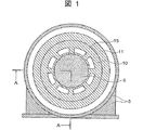
図1はこの発明の実施の形態1のエレベータ用巻上機の正面図である。
図2は図1のエレベータ用巻上機の回転軸心を通る線2−2に沿った断面図である。
図3は図2に示す実施の形態1のエレベータ用巻上機のブレーキ装置近傍の断面図である。
図4は図3に示すエレベータ用巻上機のブレーキ装置近傍の正面図である。
図5は図2のエレベータ用巻上機のモータ部近傍の断面図である。
図6は本発明の実施の形態2のエレベータ用巻上機の回転軸心に沿った断面図である。
図7は図6に示すエレベータ用巻上機のブレーキ装置近傍の断面図である。
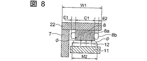
図8は図6のエレベータ用巻上機のモータ部近傍の断面図である。
図9は図6の同様のエレベータ用巻上機のモータ部近傍の断面図である。
図10は本発明の実施の形態3のエレベータ用巻上機の回転軸心に沿った断面図である。
図11は本発明の実施の形態4のエレベータ用巻上機の回転軸心に沿った断面図である。
図12は図11に示すエレベータ用巻上機のブレーキ装置近傍の断面図である。
図13は本発明の実施の形態5のエレベータ用巻上機の回転軸心に沿った断面図である。
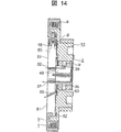
図14は本発明の実施の形態6のエレベータ用巻上機の回転軸心に沿った断面図である。
図15は本発明の実施の形態7のエレベータ用巻上機の回転軸心に沿った断面図である。
図16は本発明の実施の形態8のエレベータ用巻上機の回転軸心に沿った断面図である。
図17は本発明の実施の形態9のエレベータ用巻上機の回転軸心に沿った断面図である。
図18は本発明の実施の形態10のエレベータ用巻上機の回転軸心に沿った断面図である。
図19は本発明の実施の形態11のエレベータ用巻上機の回転軸心に沿った断面図である。1 is a front view of an elevator hoist according to
FIG. 2 is a sectional view taken along line 2-2 passing through the rotational axis of the elevator hoist of FIG.
FIG. 3 is a cross-sectional view of the vicinity of the brake device of the elevator hoist apparatus of the first embodiment shown in FIG.
FIG. 4 is a front view of the vicinity of the brake device of the elevator hoist shown in FIG.
FIG. 5 is a sectional view of the vicinity of the motor portion of the elevator hoisting machine shown in FIG.
FIG. 6 is a sectional view taken along the rotational axis of the elevator hoist according to the second embodiment of the present invention.
FIG. 7 is a cross-sectional view of the vicinity of the brake device of the elevator hoist shown in FIG.
FIG. 8 is a sectional view of the vicinity of the motor portion of the elevator hoisting machine shown in FIG.
FIG. 9 is a sectional view of the vicinity of the motor portion of the elevator hoisting machine similar to that of FIG.
FIG. 10 is a sectional view taken along the rotational axis of the elevator hoist apparatus according to the third embodiment of the present invention.
FIG. 11 is a sectional view taken along the rotational axis of the elevator hoist apparatus according to the fourth embodiment of the present invention.
12 is a sectional view of the vicinity of the brake device of the elevator hoist shown in FIG.
FIG. 13 is a sectional view taken along the rotational axis of the elevator hoist according to the fifth embodiment of the present invention.
FIG. 14 is a cross-sectional view taken along the rotational axis of the elevator hoist according to the sixth embodiment of the present invention.
FIG. 15 is a sectional view taken along the rotational axis of the elevator hoist apparatus according to the seventh embodiment of the present invention.
FIG. 16 is a sectional view taken along the rotational axis of the elevator hoist apparatus according to the eighth embodiment of the present invention.
FIG. 17 is a sectional view taken along the rotational axis of the elevator hoist apparatus according to the ninth embodiment of the present invention.
FIG. 18 is a sectional view taken along the rotational axis of the elevator hoist according to the tenth embodiment of the present invention.
FIG. 19 is a sectional view taken along the rotational axis of the elevator hoist according to the eleventh embodiment of the present invention.
実施の形態1.
図1はこの発明のエレベータ用巻上機の正面図、図2は図1の線A−Aに沿った概略断面図、図3は図2に示すブレーキ装置の拡大断面図、図4は図3のブレーキ装置の正面図、図5は図2に示すエレベータ用巻上機のモータ部の拡大断面図である。ここでは巻上機の軸方向(回転中心線方向)の寸法(厚さ)が、径方向の寸法(外径)より小さい薄形のエレベータ用巻上機の例を示している。
エレベータ用巻上機は図2に最も良く示されているように、固定体1と固定体1に回転可能に支持された回転体2とを備えている。
固定体1は、円板部分3および円板部分3の外周部に設けられた円筒部分4を持つ全体として浅い皿形の固定枠体5と、この固定枠体5の中央から直角に片持ち式に延びた主軸6と、固定枠体5の円筒部分4に支持された固定子取付部7と、この固定子取付部7に設けられてこの固定子取付部7を通る磁束を発生させる固定子8とを備えている。固定子8はコア8aとコイル8bとを備えている。
回転体2は、主軸6上で軸受9により回転可能に支持されて、固定枠体5に対して軸方向に隣接して、径方向に延びた回転枠体10と、この回転枠体10に支持されて固定子取付部7と共に磁気回路を形成する回転子取付部11と、固定子8に対向し得る位置で回転子取付部11に設けられた永久磁石である回転子12とを備えている。
エレベータ巻上機は更に、固定体1の固定枠体5及び回転体2の回転枠体10の内周に設けられた図3および図4に詳細を示すようなブレーキ装置14を備えている。ブレーキ装置14は、固定枠体5の円筒部分4に固着されたブレーキ取付板16に取付られていて、円筒部分4に対して径方向内側の位置に支持され、円筒部分4の開口部4aを貫通して回転体2の回転子取付部11の固定子が取付けられる側とは反対側の内周面に接触して制動力を与えるように設けられている。ブレーキ装置14は、ブレーキ取付板16に支持されたブレーキフレーム17と、ブレーキフレーム17によって支持された電磁コイル18と、電磁コイルによって吸引されて開放位置となり得るプランジャ19と、プランジャ19を制動位置に偏倚する圧縮バネ20と、プランジャ19に設けられ、固定枠体5の円筒部4の開口部4aを貫通して回転体2の回転子取付部11の内周面である制動面11aに向かって延びた制動部材である制動部21とを備えている。
エレベータ巻上機の回転体2は更に、回転枠体10に設けられて回転枠体10と共に回転する綱車15とを備えている。綱車15は、回転枠体10のハブ部の外周部に連続して同じ部品として一体に設けられた円筒形の部分であり、外周面にロープ溝15aを有している。綱車15はまた、回転枠体10を支持する軸受9に対して径方向外方で軸方向にほぼ対応した位置に設けられていて、軸受9に対してロープの荷重を径方向の力として作用させる。
固定枠体5の最外周部に設けられた固定子取付部7は、固定枠体5の外周部である円筒部4に設けられて、そこから径方向外側に延びた環状板部分22と、この環状板部分22から軸方向に延びた円筒部分23とを備えた断面L字型の環状の部材である。また、固定枠体5上の断面L字型の固定子取付部7は、枠体円筒部分4と協働して全体としてU字型断面部分を構成しており、このU字型断面部分内には固定子8が取り付けられている。また、回転体2の回転子取付部11は、U字型断面部分内で固定枠体円筒部分4と固定子8との間に磁石電機子である回転子12と共に配置され、回転子12は固定子8に対して径方向に対向配置されている。
エレベータ用巻上機は更に、主軸6の軸心上に取り付けられたエンコーダ24を備えており、エンコーダ用主軸25は回転枠体10に固着された支持円板26によって中心軸心上に支持されて主軸6の中心孔27内に挿入されている。
この発明のエレベータ用巻上機の構造を更に詳細に説明すると、回転枠体10の回転子取付部11は、固定枠体5の円筒部4と固定子取付部7の円筒部分23との間に入れ子状に入っており、回転子12と固定子8とが対向し、モータを構成している。固定枠体5の内側円筒部4の内周側には、ブレーキ装置14が設けられている。
ブレーキ装置14のブレーキフレーム17は、椀状の固定枠体5の円筒部4側の、回転体2と反対側の端部(即ち巻上機の外側面である図で左側)にボルト52によって固定されたブレーキ取付板16に支持され、円筒状の回転子取付部11の内周面を制動面として、固定枠体5の開口部4aを貫通する制動部21を回転子取付部11に押しつけて、綱車15の回転を制動する。すなわち、モータ停止時はブレーキ装置14の電磁コイル18は無通電状態で、ブレーキフレーム17内に収納された圧縮バネ20により制動部21が、ブレーキフレーム17から離れる方向に押されて、制動部21の先端が回転子取付部11の内周制動面に押しつけられて制動力を与える。モータ回転時は、回転を開始する前にブレーキ装置14の電磁コイル18に通電し、制動部21をブレーキフレーム17に吸引して回転子取付部11の内周制動面から制動部21を離してブレーキを解除する。ブレーキ装置14は、1台のモータに2個取りつけられている場合もあれば、1個または複数個の場合もある。
図3に示すように、ブレーキ装置14はブレーキ取付板16に取り付けられている。図3は電磁コイル18に通電したときの状態を示しており、このとき、その磁束はブレーキ装置14単体の中のみを流れ、制動部21をブレーキフレーム17に吸引する。いいかえれば、ブレーキ装置14は、ブレーキ装置14以外の他の部材の力を借りずに、単独でそのブレーキ性能を出すように設計されている。従って、回転枠体10のブレーキ装置14側の側面と、薄形巻上機のモータ回転中心線方向の綱車15と相反する外形端との厚さgOは、ブレーキ装置14のモータ回転中心線方向厚さdOと、ブレーキ取付板16の板厚と、ブレーキ取付板16にブレーキ装置14を取り付けるボルト16aの厚さと、ブレーキ装置14に隣接する固定枠体5の板厚と、ブレーキ装置14および固定枠体5間のすきまと、固定枠体5および回転枠体10間のすきまを合計した値となる。
図4にはブレーキ装置14に関連して固定枠体5の円筒部4に形成した開口部4a近傍を示してある。ブレーキ装置14からは、固定枠体5の内側円筒部4に設けた開口部4aを貫通して制動部21が回転子取付部11の制動面11aに延びており、ブレーキ作動命令により、制動部21が制動面11aに力F(図4)で押しつけられる構造となっている。固定枠体5の開口部4aが制動部21の移動を案内する機能を果たし、またブレーキ作動時に制動部21に作用する周方向の力N(図4)を支持するので、制動部21を案内するための部品や支え板を特別に設ける必要がない。
図5はエレベータ用巻上機のモータ部の固定子8(電磁石)近傍の拡大図であり、固定子(電磁石)8はコア8aと、コア8aに巻線したコイル8bとを備えている。PMモータでは、回転子側に永久磁石12が使用されるが、永久磁石12は高価なため、その材料の使用を効果の得られる最小限度に止めたいという要求もある。このため、図5に示す例では、回転体2の永久磁石12の幅MOをコアの幅COと同等にしてあり、エレベータ用巻上機のモータ部の幅WOは、固定子8のコア8aの幅COと、コイル8bの終端の寸法E1およびE2と、固定枠体5の板厚SOとの合計でほぼ決まっている。主として機械室のないエレベータに使われる従来の薄形のエレベータ用巻上機は、綱車15の回転中心線方向(軸方向)の厚さが薄くなっている。しかしエレベータ用巻上機の所要トルクが大きくなるにつれ、このような薄形のエレベータ用巻上機といえども絶対的な厚みが次第に増大していく。機械室のないエレベータでは、昇降路内のかごと昇降路壁との隙間に薄形のエレベータ用巻上機を配置するのが通例であるが、エレベータ用巻上機の厚さが増大するにつれ、事実上使用されないにもかかわらず昇降路としては占有する空間、いわゆる昇降路内のかごと昇降路壁との間のデッドスペースが増大する。このため薄形のエレベータ用巻上機に対しては、綱車回転中心線方向の厚さを更に薄くすることが要求されている。図1乃至図5に示されるエレベータ用巻上機の綱車回転中心線方向の厚さDOを薄くするには、回転枠体10のブレーキ装置側の側面と、モータ用巻上機のモータ回転中心線方向の綱車15と相対するエレベータ用巻上機の外形端との間の厚さ寸法gO(図3)を小さくし、かつモータ部の厚さWO(図5)も小さくする必要がある。
本発明の薄形のエレベータ用巻上機は、以上説明したように構成されており、従来の薄形のエレベータ用巻上機と比べると、次の点で優れている。
第1に回転部を支える構造体、すなわちハウジングが回転部の外側を覆うことが無いことである。このため、従来のものと比べると、軸方向の厚さはハウジングの板厚分だけ薄くなっている。
第2に、固定枠体5の開口部4aが、制動部21の移動時の案内機能およびブレーキ作動時に制動部21に作用する周方向の力の支持機能を果たしていることである。このため、別体の案内部品は不要であり、部品点数を削減できる。
第3に、綱車15がハウジングで覆われていない。従来の薄形のエレベータ用巻上機では、綱車がハウジングで覆われていて、エレベータ据付時のロープの張り回しや既設置エレベータのロープの定期交換のために、ロープを綱車に巻きつける作業の際には、ハウジングが邪魔となってこの作業がやりづらいという問題があったが、本発明の薄形のエレベータ用巻上機では、綱車15がハウジングで覆われていないので、このような問題は起こらない。
実施の形態2.
図6乃至図8は図3乃至図5に対応する図で、この発明の実施の形態2のエレベータ用巻上機を示す断面図である。このエレベータ用巻上機に於いては、図6に示すように、主軸6内に軸受け9に軸受潤滑油を循環供給するための流路31が設けられている。流路31は、主軸6の固定体側の端面に開口した給油口32を持ち軸方向に延びて軸受9を収容した軸受空間33内に開いた出口開口34を持つ給油路35と、主軸6の回転体側の端面に入口開口36を持ち、軸方向に延びて固定体側の端面に開いた排出口37を持つ戻り油路38とを備えている。軸受空間33は、一方は主軸6と回転枠体10との間を封止する環状のシール機構39により、また他方は回転枠体10に封止されて固着されたエンコーダ用主軸25の支持円板26によって封止されている。従って固定体1と回転体2との間の軸受9は、油漏れ防止機構によってシールされ潤滑油が循環して供給される軸受空間内に封入されている。
このように、少なくとも回転体2の回転中心線上の固定枠体5と相対する側でかつ回転体2の回転子取付部11のブレーキ制動面11aと軸受9との間には、軸受9に含まれる油の漏れを防ぐシール機構39が設けられているので、油を特に嫌う回転体2のブレーキ制動面11a側へ油が流れていって制動面11aに付着することを防止している。つまり固定枠本5の内側円筒部の制動面11aは制動力が安定するように、摩擦係数の値を安定維持することが重要であり、そのためには油が付着しない構造にする必要があるが、油漏れ防止のためのシール機構39を軸受9のモータ回転中心線方向の制動面に近い側に設けることより軸受9に含まれる潤滑油が漏れて制動面に流れていくことを防いでいる。
定期保守時には、潤滑油給油口32から流路31に新鮮な潤滑油を注入する。注入された潤滑油は軸受9を潤滑し、使用により劣化した排油は排出口37から排出される。エレベータ用巻上機の定期保守は軸受9への潤滑油注入とブレーキ装置41の調整、動作確認が主であるが、どちらもモータ回転中心線方向の固定体1側の同じ面からの作業となるので作業が容易である。またこれにより、保守作業を要しない反対側の面、即ち、綱車15がある面の間際まで、昇降路壁を寄せることが出来、昇降路スペースを極限まで縮減できる。
また、軸受け9として、無給油タイプの軸受けを用いることもできる。例えば、油が含芯されている様な無給油タイプの軸受けを用いれば、より一層油漏れの防止を図ることができる。そして、この場合には、定期保守時における潤滑油の注入の必要も無くなる。
図7にはこのエレベータ用巻上機のブレーキ装置41が示してある。ブレーキ装置41のブレーキフレーム17は、図3に示すブレーキ装置14と同様、椀状の固定枠体5に固定されたブレーキ取付板16に支持され、円筒状の回転子取付部11の内周面を制動面11aとして、制動面11aに制動部21を押しつけて、綱車15の回転を制動する。図7は、電磁コイルに通電した状態を示しているが、固定枠体5のブレーキフレーム17と近傍のブレーキフレーム以外の部材(ここでは固定枠体5およびブレーキ取付板16)をブレーキフレーム17と接触、あるいは微少すきまに設置することにより、ブレーキ装置41に通電したとき、固定枠体5のブレーキフレーム17と近傍の固定枠体5やブレーキ取付板16にも電磁コイル18からの磁束を流すことができるため、ブレーキフレーム17と近傍の固定枠体5およびブレーキ取付板16もブレーキフレーム17の一部即ち磁気回路の一部として活用できる。
つまり図3に示す例では、電磁コイル18の外側に磁束を飽和させずに通すための厚さsOの寸法を備えた板厚dOのブレーキフレーム17が必要であったが、このブレーキ装置41では図7に示すように磁性体のブレーキ取付板16の板厚をsO、固定枠体5の板厚をsOとすることで、ブレーキフレーム17の板厚をd1に小さくできる。これにより、ブレーキフレーム17をモータ回転中心線方向に薄形化でき、回転枠体10のブレーキ装置41側の側面と、エレベータ用巻上機のモータ回転中心線方向の綱車9と相対するエレベータ用巻上機外形端との厚さg1を、図3のgOより小さくできる。この結果、厚さD1(D1<実施例1図2のDO)の巻上機を実現できる。
図8は図6に示す実施の形態2のエレベータ用巻上機のモータ部の固定子8のコア8a近傍の拡大図である。モータ部の幅(軸方向寸法)を小さくするために、固定子8の総幅(コア8a+コイル8b)を必要なトルクを確保できる限界まで小さくするとともに、永久磁石12の幅M2をコアの幅C1より大きくしている。永久磁石の幅M2をコアの幅C1より大きくとると、永久磁石12の両端から出る磁束φも活用し得て、同一のトルクを得るのに必要なコア8aの幅を小さくし、モータ部の幅を小さくし、もってモータ部の厚さを薄くすることができる。尚、具体的には、永久磁石12の幅M2をコアの幅C1より数mm程度大きくすることによって、同一のトルクを得るのに必要なコア8aの幅を小さくできる。
すなわち図5と図9に示すように、モータの幅寸法は同じWOであっても、図9のモータは永久磁石12の両端からも磁束φが出てコア8aに回り込むため、図5のモータより大きなトルクが得られる。逆に、図8に示すように、コア8aの幅をCOより小さいC1とし、永久磁石12の幅を図9のM1より小さいM2にしても、図5に示したモータと同じトルクを得ることができる。このように、コア8aの幅を小さくすることにより、モータのトルクは同一で、モータ幅をWOより小さいW1にできるので、モータ部の綱車回転中心線方向の厚さを従来よりもさらに小さくできる。
このエレベータ用巻上機は、その他の点では実施の形態1のエレベータ用巻上機と同様の構造である。
実施の形態3.
図10に示すこの発明の実施の形態3の薄形のエレベータ用巻上機に於いては、ブレーキ装置43と回転枠体44との間には固定枠体がない薄形モータの例である。このエレベータ用巻上機に於いては、固定枠体5の円筒部分4に固着されてブレーキ装置43のブレーキフレーム17を支持するブレーキ取付板45が、主軸6をも片持ち式に支持している。このため、回転枠体10に対してモータ回転中心線方向に隣接する固定枠体の円板部分が省略されており、巻上機の厚さをD2にまで薄くすることができる。つまり、実施の形態1における、断面L字型の固定子取付部7が枠体円筒部分4と協働して全体としてU字型断面部分のみが固定枠体5を構成しており、このU字型断面部分内には固定子8が取り付けられている。また、回転体2の回転子取付部11は、U字型断面部分内で固定枠体円筒部分4と固定子8との間に磁石電機子である回転子12と共に配置され、回転子12は固定子8に対して径方向に対向配置されている。
すなわち、図1の実施形態1では回転枠体5の円板部分3の厚さだけ全体の厚さ寸法を小さくでき、ブレーキ装置側の側面とエレベータ用型巻上機のモータ回転中心線方向の綱車と相対するエレベータ用巻上機外形端との厚さgOをg2にすることができるため、実施形態1(図2)のエレベータ用巻上機のモータ回転中心線方向の厚さDOより小さい厚さD2の巻上機が実現できる(D2<実施形態1(図2)のDO)。ここでブレーキ取付板45は固定枠体5と結合されており、その機能は、ブレーキ装置を取りつける目的だけでなく、固定枠体5とともに主軸にかかる荷重を支える構造体の機能も兼ねている。見方を変えれば、固定枠体5の円筒部分4を支持する円板部分3がブレーキ装置14を支持していると言うこともできる。またブレーキ取付板45と固定枠体5との結合は、はめあい構造とすることもできる。その他の構造は実施形態2と同様である。また、ブレーキ取付体45は、主軸にかかる荷重を支えるための強度を確保するためにリブが設けられる構成にしても良い。
実施の形態4.
図11および図12に示す実施の形態4のエレベータ用巻上機に於いては、ブレーキ装置46のブレーキ取付板47がブレーキフレームと一体化された単一部品とされていて、ブレーキ取付板47(ブレーキフレーム)と回転枠体10との間のすきまが例えば2mm程度の微少すきまとされている。ブレーキ取付板47はブレーキフレームでもあり、固定枠体5の円筒部分4を支持する円板部分3がブレーキ装置14を支持していると言うこともできる。その他の構成は図10に示す実施の形態3と同様である。
この構成によれば、ブレーキ取付板47がブレーキフレームと一体化されているので、部品点数が減り、構造が簡素化される。図12に示すように、電磁コイル18からでる磁束の通過路である、綱車15の軸心方向の綱車15と相対する側のブレーキ装置26の外形面と電磁コイル18との間の寸法SOを、ブレーキを作動させるための磁束を通過させるのに必要最小の寸法とすることができるので、先の実施形態よりもさらに幅寸法を小さくできる。さらにブレーキ取付板47(ブレーキフレーム)と回転枠体10との間のすきまを微少とすることにより、ブレーキ装置46に通電したとき、ブレーキ装置46の電磁コイル18の磁束を回転枠体10に流すことができるため、ブレーキ取付板47に対して近傍の回転枠体10の部分もブレーキフレームの一部として活用できる。つまりブレーキフレームをモータ回転中心線方向に薄形化でき、回転枠体10のブレーキ装置46側の側面とエレベータ用巻上機のモータ回転中心線方向の綱車15と相反するエレベータ用巻上機外形端との間の厚さ寸法を、g3という小さい寸法にすることができ、ブレーキ装置46を薄形化できる。この結果、厚さD3の小さなエレベータ用の巻上機を実現できる。
実施の形態5.
図13にはこの発明の実施の形態5のエレベータ用巻上機を示す。このエレベータ用巻上機に於いては、主軸48が図11に示す実施形態4のブレーキ取付板47と同様のブレーキ取付板49と一体化された単一の部品であり、その他の点では図11に示す実施形態4のものと同様である。このエレベータ用巻上機に於いては、主軸48とブレーキ取付板49が一体化されているので、さらに部品点数が減り、構造をより簡素化できる。
実施の形態6.
図14に示す実施例6のエレベータ用巻上機の基本構造は実施例5のものと同じであるが、図に示すように、ブレーキ装置46のブレーキ取付板51は、モータの軸方向に見て回転体2の側から固定枠体5に組み込まれてボルト52で取り付けられる構造にしてある。このため、固定枠体5へのブレーキ装置46の組み付け方向と、主軸48への回転体2の組み付け方向とを同じにでき、エレベータ用巻上機の組立を一方向組立作業として組立性を向上できる。また、万一、軸受9に最も近い油漏れ防止機構である第1のシール機構39が破れて、この部分から油が漏れた場合でも、その油が回転枠体10のブレーキ制動面には行かないように、第2の油漏れ防止機構である第2のシール機構53を設けている。図示の例では第1および第2のシール機構39、52が設けられているが、必要に応じ、さらに複数の油漏れ防止機構を設けることもできる。また軸受部分から漏れた油をエレベータ用巻上機の外部に排出するための排出口55が設けられている。定期的なモータの保守点検時には、軸受油の漏れを点検する必要があるため、油の漏れ有無のための検査用穴として設けることもあるが、この油の漏れ有無の検査用穴と、排出口の両者を1つの穴で兼ねることもできる。
実施の形態7.
図15に示すこの発明の実施の形態7のエレベータ用巻上機の基本構造は図13に示す実施例5のものと同様であるが、固定枠体57がブレーキフレームおよびブレーキ取付板の作用をするように一体化して単一の部品として構成されている。従って、ブレーキフレームとブレーキ取付板とを省略でき、部品点数をさらに減らして構造をより簡素化できる。その他の点では図13のものと同様の構造である。
実施の形態8.
図16に示すエレベータ用巻上機は、モータ部がアキシャルギャップモータとされており、その他の点では図15に示す実施の形態7のものと同様の構造である。即ち、固定子60が固定子取付部7の円筒部分23でなく環状板部分22に取り付けられていて、固定子取付部7と固定枠体5の円筒部分4とで形成されたU字型断面部分内で、径方向および軸方向に延びた回転子取付部11によって囲まれた空間内に配置されている。また、回転子61が固定子60に対して軸方向に対向配置されている。
実施の形態9.
図17のエレベータ用巻上機に於いては、基本構造は図15に示す実施形態7のものと同じであるが、実施形態7のものと同様のブレーキ装置64が向きを径方向逆にして回転体の外周部に配置されている。即ち、ブレーキ装置64自体の構造は先に説明したものと同様であるが、径方向に延長された固定枠体65の外周部に設けた枠体円筒部分66の更に径方向外側に設けられていて、この円筒部分66の開口部67を通過した制動部21が回転子円筒部68の外周面である制動面68aに押しつけられる構造である。この構造によれば、ブレーキ制動面68aが回転体2の外周面となり、制動面68aの半径を大きくとれるので、小型のブレーキ装置64でも大きなブレーキトルクを得ることができる。
実施の形態10.
図18に示すエレベータ用巻上機の基本構造は図17の実施形態9と同じであるが、モータがアウタロータモータである点が相違している。実施形態9と同様、ブレーキ制動面68aが回転体2の外周面となり、制動面68aの半径を大きくとれるので、小型のブレーキ装置64でも大きなブレーキトルクを得ることができる。
実施の形態11.
図19に示すエレベータ用巻上機に於いては、主軸70が固定体1の側でなく回転体2の側に設けられている。即ち、固定体1の固定枠体5には固定枠体5から立ち上がった同心の円筒形の支持部71が設けられていて、この支持部71の内側に回転枠体10から延びた主軸70が挿入されている。支持部71の内周面と主軸70の外周面との間には軸受9が設けられていて、回転枠体10が固定枠体5に対して回転できるようにしてある。主軸70の端面からはエンコーダ用回転軸25が軸整列して延びていて、固定枠体5に取り付けられているエンコーダ24によって回転数を測定できるようにしてある。この実施の形態に於いても、軸受9用の潤滑油のための流入孔32および流出孔37が設けられており、また潤滑油の漏れ止めのためのシール39および53が設けられ、シール53から漏出した潤滑油の排出用の排出口55も設けられている。その他の構成は他の実施の形態と同じでよいが、図示の例では全体として図14の実施の形態と同様である。
尚、この発明の実施形態として以上に説明した例に於いては、回転子12として永久磁石を用いたPMモータの例で説明しているが、PMモータに限られるものではなく、この発明は例えばIPMモータやインダクションモータ等においても適用できる。
また、この発明の実施形態として以上に説明した例に於いては、軸の支持方法において、片持ち支持のもので説明しているが、この発明は軸を両持ちで支持するものにおいても適用できる。
1 is a front view of an elevator hoisting machine according to the present invention, FIG. 2 is a schematic cross-sectional view taken along line AA in FIG. 1, FIG. 3 is an enlarged cross-sectional view of the brake device shown in FIG. FIG. 5 is an enlarged cross-sectional view of the motor unit of the elevator hoisting machine shown in FIG. Here, an example of a thin type elevator hoisting machine in which the dimension (thickness) in the axial direction (rotation center line direction) of the hoisting machine is smaller than the dimension in the radial direction (outer diameter) is shown.
As best shown in FIG. 2, the elevator hoist includes a
The
The rotating
The elevator hoisting machine further includes a
The
The
The elevator hoisting machine further includes an
The structure of the elevator hoisting machine of the present invention will be described in more detail. The
The
As shown in FIG. 3, the
FIG. 4 shows the vicinity of the
FIG. 5 is an enlarged view of the vicinity of the stator 8 (electromagnet) of the motor unit of the elevator hoist. The stator (electromagnet) 8 includes a
The thin elevator hoisting machine of the present invention is configured as described above, and is excellent in the following points as compared with the conventional thin elevator hoisting machine.
First, the structure that supports the rotating part, that is, the housing does not cover the outside of the rotating part. For this reason, compared with the conventional one, the axial thickness is reduced by the thickness of the housing.
Second, the
Third, the
FIGS. 6 to 8 correspond to FIGS. 3 to 5 and are sectional views showing an elevator hoist according to
As described above, the
During regular maintenance, fresh lubricating oil is injected into the
Further, an oil-free bearing can be used as the
FIG. 7 shows a
That is, in the example shown in FIG. 3, the
FIG. 8 is an enlarged view of the vicinity of the core 8a of the
That is, as shown in FIG. 5 and FIG. 9, even if the motor has the same width dimension, the motor of FIG. 9 generates a magnetic flux φ from both ends of the
This elevator hoisting machine has the same structure as the elevator hoisting machine of the first embodiment in other points.
The thin elevator hoisting machine according to the third embodiment of the present invention shown in FIG. 10 is an example of a thin motor having no fixed frame body between the
That is, in the first embodiment of FIG. 1, the overall thickness dimension can be reduced by the thickness of the
In the elevator hoisting machine of the fourth embodiment shown in FIGS. 11 and 12, the
According to this configuration, since the
FIG. 13 shows an elevator hoist according to
The basic structure of the elevator hoist of the sixth embodiment shown in FIG. 14 is the same as that of the fifth embodiment. However, as shown in the figure, the
The basic structure of the elevator hoisting machine according to the seventh embodiment of the present invention shown in FIG. 15 is the same as that of the fifth embodiment shown in FIG. 13, but the fixed
In the elevator hoisting machine shown in FIG. 16, the motor part is an axial gap motor, and the other structure is the same as that of the seventh embodiment shown in FIG. That is, the
In the elevator hoisting machine of FIG. 17, the basic structure is the same as that of the seventh embodiment shown in FIG. 15, but the
The basic structure of the elevator hoist shown in FIG. 18 is the same as that of the ninth embodiment shown in FIG. 17, except that the motor is an outer rotor motor. As in the ninth embodiment, the
In the elevator hoist shown in FIG. 19, the
In the example described above as the embodiment of the present invention, the example of the PM motor using the permanent magnet as the
Further, in the example described above as the embodiment of the present invention, the shaft support method is described as being cantilevered, but the present invention is also applicable to the case where the shaft is supported by both ends. it can.
Claims (8)
主軸と、
上記固定枠体に設けられた固定子と、
上記主軸に支持されて上記固定枠体と軸方向に対向して径方向に延びた回転枠体と、
この回転枠体に上記固定子に対向して設けられた回転子と、
上記固定枠体の開口部を貫通して延びて、上記開口部によって径方向に案内される制動部を有するブレーキ装置と、
上記回転枠体に設けられて共に回転する綱車とを備えたエレベータ用巻上機。A fixed frame,
The spindle,
A stator provided on the fixed frame,
A rotating frame body supported by the main shaft and extending in the radial direction facing the fixed frame body in the axial direction;
A rotor provided on the rotating frame opposite to the stator;
A brake device having a braking portion extending through the opening of the fixed frame and guided in the radial direction by the opening ;
An elevator hoisting machine comprising a sheave provided on the rotating frame and rotating together.
Applications Claiming Priority (1)
| Application Number | Priority Date | Filing Date | Title |
|---|---|---|---|
| PCT/JP2003/009933 WO2005012154A1 (en) | 2003-08-05 | 2003-08-05 | Hoist for elevator |
Publications (2)
| Publication Number | Publication Date |
|---|---|
| JPWO2005012154A1 JPWO2005012154A1 (en) | 2006-09-14 |
| JP4437784B2 true JP4437784B2 (en) | 2010-03-24 |
Family
ID=34113497
Family Applications (1)
| Application Number | Title | Priority Date | Filing Date |
|---|---|---|---|
| JP2005507409A Expired - Fee Related JP4437784B2 (en) | 2003-08-05 | 2003-08-05 | Elevator hoisting machine |
Country Status (5)
| Country | Link |
|---|---|
| US (1) | US7850144B2 (en) |
| EP (1) | EP1655259B1 (en) |
| JP (1) | JP4437784B2 (en) |
| CN (1) | CN1812927A (en) |
| WO (1) | WO2005012154A1 (en) |
Families Citing this family (32)
| Publication number | Priority date | Publication date | Assignee | Title |
|---|---|---|---|---|
| CN100369798C (en) * | 2003-08-21 | 2008-02-20 | 三菱电机株式会社 | Thin hoist for elevator |
| JP2006219274A (en) * | 2005-02-14 | 2006-08-24 | Mitsubishi Electric Corp | Hoisting machine for elevator and bearing replacing method of hoisting machine for elevator |
| ATE514221T1 (en) * | 2006-04-24 | 2011-07-15 | Inventio Ag | ACCESS DRIVE FOR AN ELEVATOR |
| CN101214898B (en) * | 2007-01-04 | 2010-04-07 | 大银微系统股份有限公司 | Torque moment motor type elevator |
| KR101179773B1 (en) * | 2007-09-14 | 2012-09-04 | 미쓰비시덴키 가부시키가이샤 | Elevator hoist |
| US9016432B2 (en) | 2007-12-10 | 2015-04-28 | Rapid Egress Descent Systems Ltd. | Descent control device |
| CA2646073C (en) * | 2007-12-10 | 2011-02-01 | Rapid Egress Descent Systems Ltd. | Descent control device |
| WO2010102575A1 (en) * | 2009-03-11 | 2010-09-16 | The Chinese University Of Hong Kong | Magnetorheological actuator with multiple functions |
| CN101987711B (en) * | 2009-07-30 | 2013-02-13 | 包文丽 | Tractor used for elevator |
| CN102060224A (en) * | 2009-11-17 | 2011-05-18 | 包文丽 | Elevator driving device and supporting structure of driving rope pulley |
| JP5776163B2 (en) * | 2010-10-15 | 2015-09-09 | 株式会社明電舎 | Hoisting machine |
| JP5468028B2 (en) * | 2011-01-26 | 2014-04-09 | 株式会社日立製作所 | Thin hoisting machine for elevator |
| JP5604356B2 (en) * | 2011-04-07 | 2014-10-08 | 株式会社日立製作所 | Elevator hoisting machine and elevator device |
| CN102976187A (en) * | 2011-09-02 | 2013-03-20 | 上海三菱电梯有限公司 | Traction machine for elevator |
| JP5856908B2 (en) * | 2012-05-31 | 2016-02-10 | 株式会社日立製作所 | Elevator hoisting machine |
| JP5897455B2 (en) * | 2012-12-12 | 2016-03-30 | 株式会社日立製作所 | Elevator hoisting machine |
| JP6236143B2 (en) * | 2014-02-21 | 2017-11-22 | 株式会社日立製作所 | Elevator equipment |
| JP6344246B2 (en) * | 2015-01-15 | 2018-06-20 | 株式会社安川電機 | Rotating electric machine |
| JP6229617B2 (en) * | 2014-08-01 | 2017-11-15 | 株式会社安川電機 | robot |
| JP6340314B2 (en) * | 2014-12-26 | 2018-06-06 | 株式会社日立製作所 | Hoisting machine and elevator |
| CN105035918B (en) * | 2015-08-13 | 2017-07-18 | 於樱枝 | Elevator traction machine |
| WO2017040136A1 (en) | 2015-08-31 | 2017-03-09 | Otis Elevator Company | Optical encoder and motor assembly |
| JP6134952B1 (en) * | 2015-12-03 | 2017-05-31 | 株式会社明電舎 | Hoisting machine |
| JP6412089B2 (en) | 2016-12-01 | 2018-10-24 | ファナック株式会社 | motor |
| WO2019008761A1 (en) * | 2017-07-07 | 2019-01-10 | 三菱電機株式会社 | Elevator hoist |
| EP3444217A1 (en) * | 2017-08-17 | 2019-02-20 | KONE Corporation | Radial flux permanent magnet elevator motor |
| CN108361283B (en) * | 2018-01-16 | 2019-12-06 | 日立电梯(上海)有限公司 | Oil leakage prevention sealing device for bearing |
| JP6884262B2 (en) * | 2018-02-20 | 2021-06-09 | 三菱電機株式会社 | Hoisting machine assembly jig and hoisting machine assembly method using hoisting machine assembly jig |
| KR102656171B1 (en) * | 2019-01-25 | 2024-04-08 | 엘지전자 주식회사 | Brake device of inwheel motor and inwheel motor having the same |
| US11199049B2 (en) * | 2019-02-14 | 2021-12-14 | Tie Down, Inc. | Winch utility |
| EP4211780A1 (en) * | 2020-09-10 | 2023-07-19 | Siemens Schweiz AG | Servo drive having an electric motor and an electromagnet arranged movably on the rotor of the electric motor to apply a holding torque with contact via a remanent magnetic field |
| JP7010400B1 (en) * | 2021-03-05 | 2022-01-26 | 三菱電機株式会社 | Elevator brake device |
Family Cites Families (17)
| Publication number | Priority date | Publication date | Assignee | Title |
|---|---|---|---|---|
| JPS53140888U (en) * | 1977-04-13 | 1978-11-07 | ||
| JPS53140888A (en) | 1977-05-13 | 1978-12-08 | Senko Med Instr Mfg | Device for melting frozen blood |
| JPH0745315B2 (en) * | 1988-08-26 | 1995-05-17 | 三菱電機株式会社 | Hoisting machine |
| JPH0556618A (en) | 1991-08-23 | 1993-03-05 | Fuji Electric Co Ltd | Dc brushless spindle motor |
| JPH05186165A (en) * | 1992-01-16 | 1993-07-27 | Mitsubishi Electric Corp | Linear-motor-driven elevator device |
| JPH1179686A (en) | 1997-09-12 | 1999-03-23 | Meidensha Corp | Hoist |
| DE19832208C1 (en) | 1998-07-17 | 1999-11-04 | System Antriebstechnik Dresden | Transmission-less lift machine with synchronous external rotor motor has minimized external dimensions using construction of few and cost-effective components |
| JP4157631B2 (en) * | 1998-11-19 | 2008-10-01 | 日本エレベーター製造株式会社 | Elevator device |
| DE19906727C1 (en) * | 1999-02-18 | 2000-06-08 | System Antriebstechnik Dresden | Gearbox-less machine for lift system, has synchronous external rotor motor with rotor monitoring measurement system arranged inside axial brake and before rotor shaft end |
| JP3537348B2 (en) | 1999-04-05 | 2004-06-14 | 三菱電機株式会社 | Traction elevator hoist |
| JP2001072358A (en) * | 1999-07-02 | 2001-03-21 | Teijin Seiki Co Ltd | Elevator hoisting machine |
| JP2001151443A (en) | 1999-11-30 | 2001-06-05 | Toshiba Digital Media Engineering Corp | Winder and elevator device |
| JP4522619B2 (en) | 2000-08-09 | 2010-08-11 | 株式会社ダイヤメット | Sintered oil-impregnated bearing, manufacturing method thereof and motor |
| JP2002284486A (en) | 2001-03-22 | 2002-10-03 | Sanyo Kogyo Kk | Hoist gear |
| JP2003104666A (en) * | 2001-09-28 | 2003-04-09 | Meidensha Corp | Hoisting machine and elevator device |
| JP2003106348A (en) * | 2001-09-28 | 2003-04-09 | Meidensha Corp | Brake device and hoist |
| US7353913B2 (en) * | 2003-06-05 | 2008-04-08 | Mitsubishi Denki Kabushiki Kaisha | Elevator hoisting machine and motor |
-
2003
- 2003-08-05 CN CNA038268485A patent/CN1812927A/en active Pending
- 2003-08-05 US US10/567,343 patent/US7850144B2/en not_active Expired - Fee Related
- 2003-08-05 JP JP2005507409A patent/JP4437784B2/en not_active Expired - Fee Related
- 2003-08-05 WO PCT/JP2003/009933 patent/WO2005012154A1/en active Application Filing
- 2003-08-05 EP EP03817790A patent/EP1655259B1/en not_active Expired - Lifetime
Also Published As
| Publication number | Publication date |
|---|---|
| EP1655259A1 (en) | 2006-05-10 |
| US7850144B2 (en) | 2010-12-14 |
| JPWO2005012154A1 (en) | 2006-09-14 |
| EP1655259A4 (en) | 2009-08-12 |
| EP1655259B1 (en) | 2011-06-15 |
| US20080164102A1 (en) | 2008-07-10 |
| CN1812927A (en) | 2006-08-02 |
| WO2005012154A1 (en) | 2005-02-10 |
Similar Documents
| Publication | Publication Date | Title |
|---|---|---|
| JP4437784B2 (en) | Elevator hoisting machine | |
| EP1630120B1 (en) | Hoist and motor for elevator | |
| JP5710396B2 (en) | Elevator hoisting machine | |
| JP5263865B2 (en) | Electric motor for hoisting machine | |
| JP4178075B2 (en) | Elevator hoisting machine | |
| JP5809531B2 (en) | Elevator thin hoist | |
| JP2004299824A (en) | Elevator hoisting machine | |
| US20040074703A1 (en) | Elevating drive apparatus for elevator | |
| KR100817664B1 (en) | Hoist for elevator | |
| KR100764324B1 (en) | Hoist for elevator | |
| CA2217299A1 (en) | Compact drive for lifts | |
| JP2011026095A (en) | Electromagnetic brake device for motor and hoisting machine for elevator using the same | |
| JP5289318B2 (en) | Elevator hoisting machine | |
| JP4164067B2 (en) | Elevator hoisting machine | |
| KR100441043B1 (en) | Slimming type traction machine | |
| JP2010100373A (en) | Elevator hoisting machine and elevator device | |
| JP7261320B2 (en) | Hoist and elevator | |
| JP5223248B2 (en) | Elevator sheave equipment | |
| JP2004189395A (en) | Elevator hoisting machine and braking device for the same | |
| JP7274915B2 (en) | electric motor with brake | |
| WO2023238269A1 (en) | Hoist and elevator | |
| KR100621242B1 (en) | Hoist and motor for elevator | |
| WO2018142585A1 (en) | Inner rotor-type hoist | |
| JPH0219630Y2 (en) | ||
| JP2005314039A (en) | Hoist for elevator |
Legal Events
| Date | Code | Title | Description |
|---|---|---|---|
| A621 | Written request for application examination |
Free format text: JAPANESE INTERMEDIATE CODE: A621 Effective date: 20060704 |
|
| A131 | Notification of reasons for refusal |
Free format text: JAPANESE INTERMEDIATE CODE: A131 Effective date: 20090728 |
|
| A521 | Request for written amendment filed |
Free format text: JAPANESE INTERMEDIATE CODE: A523 Effective date: 20090924 |
|
| TRDD | Decision of grant or rejection written | ||
| A01 | Written decision to grant a patent or to grant a registration (utility model) |
Free format text: JAPANESE INTERMEDIATE CODE: A01 Effective date: 20091222 |
|
| A01 | Written decision to grant a patent or to grant a registration (utility model) |
Free format text: JAPANESE INTERMEDIATE CODE: A01 |
|
| A61 | First payment of annual fees (during grant procedure) |
Free format text: JAPANESE INTERMEDIATE CODE: A61 Effective date: 20091224 |
|
| FPAY | Renewal fee payment (event date is renewal date of database) |
Free format text: PAYMENT UNTIL: 20130115 Year of fee payment: 3 |
|
| R150 | Certificate of patent or registration of utility model |
Ref document number: 4437784 Country of ref document: JP Free format text: JAPANESE INTERMEDIATE CODE: R150 Free format text: JAPANESE INTERMEDIATE CODE: R150 |
|
| FPAY | Renewal fee payment (event date is renewal date of database) |
Free format text: PAYMENT UNTIL: 20130115 Year of fee payment: 3 |
|
| R250 | Receipt of annual fees |
Free format text: JAPANESE INTERMEDIATE CODE: R250 |
|
| R250 | Receipt of annual fees |
Free format text: JAPANESE INTERMEDIATE CODE: R250 |
|
| R250 | Receipt of annual fees |
Free format text: JAPANESE INTERMEDIATE CODE: R250 |
|
| R250 | Receipt of annual fees |
Free format text: JAPANESE INTERMEDIATE CODE: R250 |
|
| R250 | Receipt of annual fees |
Free format text: JAPANESE INTERMEDIATE CODE: R250 |
|
| R250 | Receipt of annual fees |
Free format text: JAPANESE INTERMEDIATE CODE: R250 |
|
| LAPS | Cancellation because of no payment of annual fees |