JP4437585B2 - Guide bush inside diameter adjuster for spindle moving type automatic lathe - Google Patents
Guide bush inside diameter adjuster for spindle moving type automatic lathe Download PDFInfo
- Publication number
- JP4437585B2 JP4437585B2 JP2000016540A JP2000016540A JP4437585B2 JP 4437585 B2 JP4437585 B2 JP 4437585B2 JP 2000016540 A JP2000016540 A JP 2000016540A JP 2000016540 A JP2000016540 A JP 2000016540A JP 4437585 B2 JP4437585 B2 JP 4437585B2
- Authority
- JP
- Japan
- Prior art keywords
- guide bush
- peripheral surface
- spindle
- piezoelectric actuator
- outer peripheral
- Prior art date
- Legal status (The legal status is an assumption and is not a legal conclusion. Google has not performed a legal analysis and makes no representation as to the accuracy of the status listed.)
- Expired - Fee Related
Links
Images


Description
【0001】
【発明の属する技術分野】
本発明は、主軸移動型自動旋盤のガイドブッシュ内径調整装置、特に、主軸移動型自動旋盤のガイドブッシュの内周面とガイドブッシュに挿通された棒材の外周面との間の間隔を精密に調整すると共に、棒材を把持することができるガイドブッシュ内径調整装置に関する。
【0002】
【従来の技術】
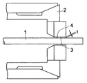
主軸移動型自動旋盤においては、棒材1は直径にバラツキがあること、ガイドブッシュ2が固定型の場合は、通常棒材1が高速で回転しているために、図1に示すように、ガイドブッシュ2の内周面3と棒材1の外周面4との間に或る程度の間隔tを設けなければならない。しかも、棒材1を精度良く加工し、しかも、焼き付きや食いつき(いわゆるカジリ)をなくするためには、この間隔tは、棒材1の直径、その材質、荒加工または仕上げ加工、加工内容、加工速度などの加工条件(切削条件)によって変わるので、その都度適切な大きさにすることが必要である。
【0003】
所で、特開平11−328804号は、主軸移動型自動旋盤のガイドブッシュの内径と棒材の外周面との間の間隔を調整する装置の一例を開示している。この間隔調整装置では、調整ねじをクランプしておき主軸を低速で回転させることによって調整ねじと螺合しているガイドブッシュを回転させて上記の間隔をつめ、主軸モータ又はガイドブッシュモータのトルクが設定値に達した時に主軸モータ又はガイドブッシュモータを所定角度逆転させ、ついでこのモータを所定角度正転させ、最後に調整ナットを解除することによって間隔調整を行っている。
【0004】
従って、この公知の間隔調整装置では、間隔調整を棒材の加工中に行うことができず、棒材の加工を停止して行わなければならず、調整時間は完全なロスタイムとなってしまうし、調整が複雑であるという問題があった。さらに、調整ねじとガイドブッシュのねじ部との間にいわゆるガタがあるために作動にヒステリシスが生じ、間隔調整は精密に行われないという問題もあった。
【0005】
【発明が解決しようとする課題】
本発明が解決しようとする課題は、棒材の加工段取りの場合は短時間で、加工中は加工を中断せずロス時間なくしかも短時間で、ガイドブッシュの内周面とこれに挿通された棒材の外周面との間の間隔を正確に、かつ、簡単に調整できる主軸移動型自動旋盤のガイドブッシュ内径調整装置を提供することにある。
【0006】
本発明が解決しようとする他の課題は、自己伸長手段を用いて主軸移動型自動旋盤の主軸のコレットチャックによる棒材の把持を行うように制御される主軸移動型自動旋盤のガイドブッシュ内径調整装置を提供することにある。
【0007】
【課題を解決するための手段】
本発明の課題を解決するために、主軸移動型自動旋盤のガイドブッシュ内径調整装置は、加工対象の棒材を把持する主軸移動型自動旋盤の主軸の前方に直列共軸に配置され、後端が該主軸の方に向いた筒状をなし、先端側には円錐台形の外周面が形成されて弾性的に拡径・縮径が可能なガイドブッシュと、後端が前記主軸の方に向いた筒状をなし、先端側には前記ガイドブッシュの前記外周面との係合が強まるほど該ガイドブッシュの該外周面を強く半径方向内側に押圧して該ガイドブッシュの内径を小さくするように該ガイドブッシュの該外周面と相補的形状の円錐台形の内周面が形成され、該ガイドブッシュを囲繞すると共に該ガイドブッシュと軸方向に相対運動を行うことができるガイドブッシュスリーブとを有する主軸移動型自動旋盤のガイドブッシュ内径調整装置において、入力電圧に応じて任意量伸びる圧電アクチュエータと、前記ガイドブッシュの前記外周面と前記ガイドブッシュスリーブの前記内周面とが相互から離間するように作用する付勢手段とから成り、前記入力電圧に応じて前記圧電アクチュエータの伸び量が多くなるにつれて前記ガイドブッシュの前記外周面と前記ガイドブッシュスリーブの前記内周面の係合が大きくなりこの係合の度合いに応じて該ガイドブッシュの内周面の縮径の大きさが定まるように構成され、前記圧電アクチュエータの伸長により、前記棒材の加工前或は加工中に前記ガイドブッシュの前記内周面と該ガイドブッシュを貫通する前記棒材の外周面との間の間隔を調整する間隔調整と、前記圧電アクチュエータの伸長により、前記棒材の加工前或は加工中に前記ガイドブッシュの前記内周面を該ガイドブッシュを貫通する前記棒材の外周面に圧接させて該ガイドブッシュに該棒材を固定把持させる棒材把持とが可能である、ことを特徴とする。
【0008】
又、前記ガイドブッシュスリーブの前記内周面は前記ガイドブッシュの前記外周面の外側から係合するように構成され、前記圧電アクチュエータは一端が前記ガイドブッシュスリーブの一部分に係合し、該圧電アクチュエータの他端は前記ガイドブッシュの後端側の一部分に係合すると共に該圧電アクチュエータの伸びが該ガイドブッシュの軸に平行に生じるように設けることができる。
【0009】
又、前記主軸を回転させる主軸回転電動機に該主軸回転電動機のトルクを検出するトルク検出装置を設け、該主軸回転電動機のトルクが所定値以上になった時に該トルク検出装置によって検出されたトルクに基づき前記ガイドブッシュを拡径するように前記圧電アクチュエータを縮ませることができる。
【0010】
又、前記主軸が該主軸及び前記ガイドブッシュに挿通されている前記棒材を開放して該棒材の加工開始位置に戻るまで前記ガイドブッシュが該棒材を把持するように前記圧電アクチュエータを伸長させることもできる。
又、前記棒材を該主軸と共に把持するように前記圧電アクチュエータを伸長させることができる。
又、前記主軸移動型自動旋盤は主軸移動・割出型多軸自動旋盤であってもよい。
【0011】
【発明の実施の形態】
以下、図面を参照して、本発明の主軸移動型自動旋盤のガイドブッシュ内径調整装置を実施の形態について説明する。
【0012】
図1はガイドブッシュ2の内周面3とこれに挿通される棒材1の外周面4との間に間隔tを形成した状態の縦断面を示す。図3は、本発明のガイドブッシュ内径調整装置の1実施形態をガイドブッシュ及びガイドブッシュスリーブと共に縦断面図で示したもの、図4はコレットチャックのクランプ・アンクランプ手段及び主軸移動手段の断面図である。
【0013】
以下の説明で、主軸移動・割出型多軸自動旋盤とは、後述の主軸割出ドラム内に複数の主軸を主軸割出ドラムの軸に平行にかつその円周方向に等配し、主軸割出ドラムの回転によって主軸を割り出すと共に主軸をその軸方向に往復動させる構造のものをいう。さらに、棒材1の加工側を前方、その反対側を後方と呼ぶ。
【0014】
先ず、本発明の第1の実施形態を説明する。図3及び4において、主軸移動・割出型多軸自動旋盤のコラム81内に主軸割出ドラム割出電動機85(図4に一部が示されている)により前側軸受82(図3)及び後側軸受83(図4)を介して回転割出可能に設けられた主軸割出ドラム84内にその軸と平行にかつ円周方向に等配された複数の主軸6を設けている。主軸割出ドラム84の前面に、該ドラムと共軸に該ドラムと共に回転するガイドブッシュハウジング受け5が設けられ、これの前面に固定されたガイドブッシュハウジング15内にガイドブッシュ2が主軸6と同軸に受けられている。
【0015】
ガイドブッシュ2は、ヘッド部9と、これから後方へ延びる実質的に筒状の胴部10と、胴部10に接続された後述の接続部材28とから成る。ヘッド部9は、後方へ向かって減径する円錐台形の外周面7と、円筒形の内周面3と、この内周面3で規定され棒材1を通過させる中心孔8とを有し、弾性的に拡径・縮径可能になっている。このガイドブッシュ2をガイドブッシュスリーブ11が共軸に囲繞している。ガイドブッシュスリーブ11は、ガイドブッシュ2のヘッド部9の円錐台形の外周面7と相補的な円錐台形の内周面12aを前端部に有する筒状胴部12と、これの後方に設けられた環状フランジ部13と、これから更に後方へ延びる円筒部14から成る。
【0016】
ガイドブッシュハウジング15は主軸割出ドラム84と共軸な環状部材で、ガイドブッシュハウジング受け5の円筒状内周面16に嵌合する筒状の胴部17とその前側に形成された環状フランジ部18とから成る。ガイドブッシュハウジング受け5は前側軸受82の内輪を保持する役目もしている。環状フランジ部18はボルト19によってガイドブッシュハウジング受け5の前面に固定されている。また、ガイドブッシュスリーブ11は、環状フランジ部13がねじ棒31Aによって環状のガイドブッシュハウジング15の環状フランジ部18に固定されている。部材20,21は組み合わさってガイドブッシュ2の蓋22になっている。
【0017】
接続部材28は、ガイドブッシュ2に共軸な環状フランジ部29とそれから前方へ延びる筒状部30とから成る。この環状フランジ部29の外周面はガイドブッシュハウジング受け5の内周面と僅かに離間して配置されている。筒状部30はその外周面がガイドブッシュスリーブ11の円筒部14の内周面に摺接している。この筒状部30の前端部はガイドブッシュ2の胴部10の後端部に螺合固定されており、ガイドブッシュ2の筒状胴部12と一体的になり、ガイドブッシュ2の一部を構成しており、接続部材28の往復動によりガイドブッシュ2が往復動するようになっている。
【0018】
ガイドブッシュハウジング15の胴部17に、この軸に平行にねじ棒31Bが螺合固定されている。接続部材28の環状フランジ部29の、各ねじ棒31Bに対応する部分に半径方向に延びるみぞ部32が形成されている。このみぞ部32内に、接続部材28の環状フランジ部29を遊嵌貫通したねじ棒31Bの後端部が延びている。ねじ棒31Bの後端にヘッド部33が形成され、これと接続部材28の環状フランジ部29のみぞ部32の底壁との間のねじ棒31Bの部分に付勢手段の一種である圧縮コイルばね34が巻回されている。そして、この圧縮コイルばね34で接続部材28が常時前方へ弾性付勢されている。接続部材28の前方への移動は接続部材28の前面がガイドブッシュハウジング15の胴部17の後面に当たって制限されるが、その移動分だけガイドブッシュ2が前進し、そのばね力によって最も開いた状態になる。
【0019】
35は、例えば、株式会社メガセラ製のピエゾポジショナーのようにピエゾ素子を用いた圧電アクチュエータであり、印加される入力電圧に応じて伸縮する。圧電アクチュエータ35は、例えば、円筒形のように細長く形成され、ガイドブッシュハウジング15内の、各ガイドブッシュ2から見て半径方向内側に軸方向に形成された取付孔36、ガイドブッシュスリーブ11の環状フランジ部13の後側面内に形成された盲孔状の取付孔37及び接続部材28の環状フランジ部29の前側面内に形成された盲孔状の取付孔38内に挿入されている。接続部材28の環状フランジ部29に形成された小径のねじ孔39にストッパねじ40が螺合されている。そして、圧電アクチュエータ35の後端面中央部に形成された突起41がストッパねじ40に、圧電アクチュエータ35の前端面がガイドブッシュスリーブ11の環状フランジ部13の取付孔37の底面に当接している。圧電アクチュエータ35から電線42が導出され、入力電圧を発生する可変電圧装置(入力手段88(図2)の一種を構成する)に接続されている。ここで、圧電アクチュエータ35と付勢手段を成す圧縮コイルばね34とは自己伸長手段61(図2)の一種を構成する。
【0020】
図2及び3を参照して、間隔tを変更する方法を説明する。変更すべき間隔tを操作盤64に入力すると、制御装置65はこの間隔tに対応して可変電圧装置を制御し、これからの入力電圧で圧電アクチュエータ35が所定量伸長する。圧電アクチュエータ35が伸長すると、接続部材28を介して圧縮コイルばね34の付勢力に抗してガイドブッシュスリーブ11を前進させ、その円錐台形内周面でガイドブッシュ2のヘッド部9の円錐台形外周面を押圧し前記間隔tを狭める。
【0021】
圧電アクチュエータ35は、印加電圧量と伸び量とが正確に対応し、印加電圧が増加するにつれて伸び量が多くなる。この伸び量はガイドブッシュ2の移動量に等しいので、ガイドブッシュ2の内径の調整量、ひいては間隔tは圧電アクチュエータ35の伸び量に正確に対応し、従って、圧電アクチュエータ35への印加電圧量に正確に対応する。それ故に、印加電圧を制御することによってガイドブッシュ2の内径の調整量、ひいては間隔tは正確に調整できることになる。そして、圧電アクチュエータ35の伸びを直接ガイドブッシュ2に伝達するために、調整精度は、5μm以下の高精度にも達する。
【0022】
この圧電アクチュエータ35による間隔tの調整は、自動旋盤を停止させる必要が全くなく、操作盤64から棒材1の加工中に行うことができるから、調整のために自動旋盤を停めてロス時間が発生することがない。また、棒材加工段取りで間隔tの調整を行う場合も、この調整はロス時間が少なく正確かつ容易である。
【0023】
次に、主軸6について述べる。主軸6は、案内主軸43と、これに軸方向に移動可能に設けられたクイル主軸86とから成る。図3及び4に示す通り、案内主軸43は、実質的に円筒状スリーブ状のもので、主軸割出ドラム84内に各ガイドブッシュ2の後端から後方へガイドブッシュ2と共軸に設けられている。そして、案内主軸43は主軸割出ドラム84にビルトインされた主軸回転電動機44によって自らの軸を中心にして所定の速度で回転するようになっている。案内主軸43の後端に雌スプライン部材87(図4)が固定されている。
【0024】
クイル主軸86は、スプライン軸46と、ドローチューブ50と、らせん皿ばね52、コレットチャック48、コレットチャックスリーブ47及び圧縮コイルばね23から成る。このスプライン軸46はその外周面に雌スプライン部材87の内周に形成された雌スプラインに係合するスプライン45を有し、案内主軸43にその軸方向に往復動可能に挿入されている。
【0025】
スプライン軸46の前端部内に円筒孔46aを形成し、この中に前端部に円錐台形内周面を有するコレットチャックスリーブ47を挿入している。コレットチャックスリーブ47の中にその円錐台形内周面の相補的な円錐台形外周面を有するコレットチャック48を挿入している。コレットチャック48は、スプライン軸46の前端部に固定された前面部にナット49が設けられている。スプライン軸46にドローチューブ50がスプライン軸46に対して共軸にそしてスプライン軸46の軸方向に往復動できるように挿入されている。ドローチューブ50の前端は円筒孔46aの内周面と摺接する増径部51になっている。
【0026】
円筒孔46a内のドローチューブ50の増径部51の後端面と円筒孔46aの内端面との間にらせん皿ばね52が設けられドローチューブ50を前方へ弾性付勢している。また、コレットチャック48の後端とコレットチャックスリーブ47の中央孔の内端壁との間に弱い圧縮コイルばね23が設けられ、コレットチャック48を常時コレットチャックスリーブ47から押し出す方向(即ち、前方向)へ弾性付勢している。
【0027】
ドローチューブ50が前進位置にある場合は、らせん皿ばね52により増径部51の前面がコレットチャックスリーブ47を前方へ押し、コレットチャックスリーブ47の先端部の円錐台形内周面がコレットチャック48のヘッド部の円錐台形外周面を押して、コレットチャック48を縮径させてこれに棒材1を把持させる。他方、ドローチューブ50がらせん皿ばね52の付勢力に抗して後退すると、増径部51も後退する。この後退によって増径部51の前面がコレットチャックスリーブ47から離れようとするが、圧縮コイルばね23によってコレットチャックスリーブ47は後方へ押され、その後端は増径部51の前面に押圧される。このため、コレットチャックスリーブ47はコレットチャック48から後退し、コレットチャック48は拡径して棒材1を離す。従って、ドローチューブ50の前進及び後退によってコレットチャック48の棒材1に対するクランプ及びアンクランプが行われる。このクランプ及びアンクランプのためのドローチューブ50の前進・後退はクランプ・アンクランプ手段63を成す後述のピストン−シリンダ・アセンブリ57で達成される。
【0028】
スプライン軸46の後端部にこのスプライン軸46をその軸方向に前進後退させる主軸移動手段62を設ける。図4の場合は、主軸移動手段62として、環状マグネット53とこれを囲繞しリニアモータコイルを内蔵したコイル54とを有する円筒形リニアモータ55を用いている。円筒形リニアモータ55はそのハウジング24が主軸割出ドラム84に固定され、コイル54はその中に筒状にかつスプライン軸46と共軸に形成されている。コイル54の円筒状孔内に、スプライン軸46と共軸なマグネットスリーブ25がコイル54に対して軸方向に往復動可能に挿入されている。マグネットスリーブ25の外周面にコイル54と対峙する複数個の環状マグネット53が形成されている。マグネットスリーブ25は次に述べるピストン−シリンダ・アセンブリ57を介してスプライン軸46に相対的に回転可能ではあるが軸方向に相互に不動に設けられている。
【0029】
円筒形リニアモータ55によって、スプライン軸46は、コレットチャック48、コレットチャックスリーブ47、ドローチューブ50と共に所定の速度で軸方向の所定の向きへ移動される。しかし、主軸移動手段62は、これに限定されず、例えば、サーボモータとボールねじ−ナット・アセンブリーとの組合せなどの他の適当なものでよい。
【0030】
図4に示すように、コレットチャック48のクランプ及びアンクランプを行うピストン−シリンダ・アセンブリ57は、シリンダ58と、ピストン59と、これらの間に形成されたオイルチャンバ60とから成る。シリンダ58は、スプライン軸46の後部分を取り巻く環状のもので、外周面でマグネットスリーブ25の内周面に保持され、内周面で軸受73を介してスプライン軸46に相対的に回転可能であるが軸方向には不動に接続されている。ピストン59もスプライン軸46後部分を囲繞する環状のもので、シリンダ58の後側にあって、外周面でマグネットスリーブ25の内周面に軸方向に往復動できるように摺接されている。スプライン軸46の後端から突出したドローチューブ50の後端部に連結スリーブ74が固定されており、ピストン59は、連結スリーブ74と軸受75とを介してドローチューブ50の後端に相対的に回転可能であるが軸方向には不動に接続されている。オイルチャンバ60がオイルパイプ76に接続されている。
【0031】
オイルチャンバ60に圧油の供給がない時又はオイルチャンバ60から圧油が排出されている時は、ドローチューブ50は前進位置にあり、上述の通り、コレットチャック48はクランプの状態になり、棒材1を把持する。他方、オイルチャンバ60に圧油が供給されると、ピストン59が後退し、これと共にドローチューブ50も後退して、上述の通り、コレットチャック48はアンクランプの状態になり、棒材1を開放する。
【0032】
主軸回転電動機44にトルク検出装置(トルク検出手段)67を設けることにより、所定以上のトルクが検出された時に、制御装置65を介して圧電アクチュエータ35(自己伸長手段61)を制御し、間隔tを広げて、ガイドブッシュ2と棒材1との間の食いつき(いわゆるカジリ)や焼きつきが生じることがなくなる(図2)。
【0033】
圧電アクチュエータ35は、ガイドブッシュ2の縮径量を大きくしてそれによって棒材1を把持固定するようにすることができる。そうすれば、棒材1を停止させてミリング加工やドリル加工を行うようにすることができるし、ガイドブッシュ2で棒材1を把持している間にコレットチャック48をアンクランプの状態にして、次の加工送りのために主軸6を後退させるのに使用することもできる。
【0034】
このように圧電アクチュエータ35を棒材1の把持に用いることができるようにすると、既に述べたクランプ・アンクランプ手段63及び主軸移動手段62と共に用いて、棒材1の加工送りを自動的に所定回数繰り返して行うことに適用することができる。この加工送りを繰り返す工程をムカデ工程と呼ぶことにし、それを図1のブロック図と図5のフローチャートを用いて図3及び図4を参照して以下に説明する。なお、圧電アクチュエータ35は自己伸長手段61に含められることはすでに述べたとおりである。
【0035】
ステップ 1:クランプ・アンクランプ手段63をクランプの状態にし、コレットチャック48で棒材1を把持させる。
ステップ 2: 自己伸長手段61に所望の低い電圧を印加してガイドブッシュ2を開放する。
ステップ 3: ステップ1及び2の状態を維持しながら主軸回転電動機44によって主軸6を所定の回転数で回転させる。
ステップ 4: ついで、コレットチャック48で棒材1を把持したまま、主軸移動手段62(円筒形リニアモータ55)によって主軸6を加工開始位置から加工終了位置まで所定の送り速度で加工送りさせる。即ち、棒材1は加工送りされ、工具66で加工される。この時に、ガイドブッシュ2の内周面3と棒材1の外周面4との間の間隔tを適正な値に調整することができる。
ステップ 5: ガイドブッシュ2の直前に配置されたバイトなどの工具66により所定の加工が終了すると、主軸移動手段62(円筒形リニアモータ55)及び主軸回転電動機44を停止して主軸6の送り及び棒材1の回転を停止させる。
ステップ 6: 自己伸長手段61に所望の高い電圧を印加してガイドブッシュ2を縮径して棒材1を把持させる。
ステップ 7: クランプ・アンクランプ手段63をアンクランプの状態にし、棒材1からコレットチャック48を開放する。
ステップ 8: 主軸6を加工開始位置へ戻す。
ステップ 9: 以上のステップ1から8までで加工の1工程が完了する。これで次の加工がなくNOであれば、全加工は終了(END)する。しかし、次の加工がありYESであれば、ステップ1へ戻り、ステップ1から8までの工程が自動的に必要回数繰り返えされる。以上は、操作盤64への入力により制御装置65によって行われる(図2)。
【0036】
図6は、本発明の自己伸長手段の他の実施形態の縦断面を示す。図3と同じ部分・要素には同じ参照番号を付して示し、それらの説明は省略する。この自己伸長手段61は油圧ピストン−シリンダ・アセンブリ68で、シリンダ69と、この中で往復動するピストン70と、これらによって規定されるオイルチャンバ71とから成り、オイルチャンバ71に対して油圧供給排出装置72により適宜な圧油を供給したり排出することによってガイドブッシュ2の内周面3と棒材1の外周面4との間の間隔tを所望の値に設定できるし、ガイドブッシュ2に棒材1を把持させたり開放させたりすることも可能である。従って、ムカデ工程にも適用できる。なお、油圧ピストン−シリンダ・アセンブリ68と最初の実施形態で説明した圧縮コイルばね34は自己伸長手段61を構成する。また、油圧ピストン−シリンダ・アセンプリ68は空圧ピストン−シリンダ・アセンブリーに換えることもでき、この場合油圧供給装置72を空圧供給装置に換える。ここでは、入力手段88は圧油であり、制御盤64によって制御される。
【0037】
以上に本発明を主軸移動・割出型多軸自動旋盤に用いた例で説明してきたが、主軸移動型単軸自動旋盤や主軸移動・非割出型多軸自動旋盤にも用いることができる。
【0038】
【発明の効果】
本発明に基づく主軸移動型自動旋盤のガイドブッシュ内径調整装置によれば、棒材の加工段取りの場合は短時間で、加工中は加工を中断せずロス時間なく、しかも、短時間で、ガイドブッシュの内周面とこれに挿通された棒材の外周面との間の間隔を正確に簡単に調整できるという効果がある。また、主軸移動型自動旋盤の棒材送り用主軸のコレットチャックによる把持と同時又は異時に棒材の把持を行う工程に適用でき、ムカデ工程を自動的に行うことに適用できるという効果もある。
【図面の簡単な説明】
【図1】主軸移動型自動旋盤において、ガイドブッシュの内周面とこれに挿通される棒材の外周面との間に間隔を形成した状態の縦断面図である。
【図2】図3、4及び図5に基づく本発明の主軸移動型自動旋盤の棒材加工制御のブロック図である。
【図3】本発明のガイドブッシュ内径調整装置の1実施形態を主軸移動型自動旋盤の前半に設けた場合の縦断面図である。
【図4】主軸、コレットチャックのクランプ・アンクランプ手段及び棒材送り手段回りの主軸自動旋盤の後半部の縦断面図である。
【図5】本発明のガイドブッシュ内径調整装置を主軸用のクランプ・アンクランプ手段及び棒材送り手段と共に用いて加工位置へ棒材を供給するフローチャートである。
【図6】本発明のガイドブッシュ内径調整装置の他の実施形態の主要部の縦断面図である。
【符号の説明】
1 棒材
2 ガイドブッシュ
3 内周面
4 外周面
6 主軸
7 外周面
8 中心孔
9 ヘッド部
11 ガイドブッシュスリーブ
34 圧縮コイルばね(付勢手段)
35 圧電アクチュエータ
43 案内主軸
44 主軸回転電動機
46 スプライン軸
47 コレットチャックスリーブ
48 コレットチャック
50 ドローチューブ
52 らせん皿ばね
55 円筒形リニアモータ
57 ピストン−シリンダ・アセンブリ
61 自己伸長手段
62 主軸移動手段
63 クランプ・アンクランプ手段
64 操作盤
65 制御装置
67 トルク検出装置
68 油圧ピストン−シリンダ・アセンブリ
69 シリンダ
70 ピストン
71 オイルチャンバ
72 油圧供給排出装置
73 軸受
81 コラム
84 主軸割出ドラム
85 主軸割出ドラム割出電動機
86 クイル主軸
87 雌スプライン部材
88 入力手段
t 間隔[0001]
BACKGROUND OF THE INVENTION
The present invention relates to a guide bush inner diameter adjusting device for a spindle moving type automatic lathe, and more particularly, to accurately adjust the distance between the inner peripheral surface of the guide bush of the spindle moving type automatic lathe and the outer peripheral surface of a bar inserted through the guide bush. The present invention relates to a guide bush inner diameter adjusting device capable of adjusting and holding a bar.
[0002]
[Prior art]
In the spindle moving type automatic lathe, the diameter of the
[0003]
Japanese Patent Laid-Open No. 11-328804 discloses an example of an apparatus for adjusting the distance between the inner diameter of the guide bush of the spindle moving automatic lathe and the outer peripheral surface of the bar. In this distance adjusting device, the adjusting screw is clamped and the main shaft is rotated at a low speed to rotate the guide bush screwed to the adjusting screw, and the above-mentioned distance is filled, so that the torque of the main shaft motor or the guide bush motor is increased. When the set value is reached, the spindle motor or the guide bush motor is reversely rotated by a predetermined angle, then the motor is rotated forward by a predetermined angle, and finally the adjustment nut is released to adjust the interval.
[0004]
Therefore, in this known spacing adjusting device, the spacing cannot be adjusted during the processing of the bar, and the processing of the bar must be stopped, and the adjustment time becomes a complete loss time. There was a problem that the adjustment was complicated. Furthermore, since there is a so-called play between the adjusting screw and the threaded portion of the guide bush, there is a problem that hysteresis occurs in the operation and the distance adjustment is not performed accurately.
[0005]
[Problems to be solved by the invention]
The problem to be solved by the present invention is that it is inserted in the guide bush inner peripheral surface in a short time in the case of processing of the rod material, without interrupting the processing and without a loss time during the processing. It is an object of the present invention to provide a guide bush inner diameter adjusting device for a spindle moving type automatic lathe capable of accurately and easily adjusting a distance between the outer peripheral surface of a bar material.
[0006]
Another problem to be solved by the present invention is to adjust the inner diameter of the guide bushing of the spindle moving type automatic lathe controlled so as to hold the bar by the collet chuck of the spindle of the spindle moving type automatic lathe using self-extending means. To provide an apparatus.
[0007]
[Means for Solving the Problems]
In order to solve the problems of the present invention, a guide bush inner diameter adjusting device for a spindle moving type automatic lathe is:In front of the spindle of the spindle moving type automatic lathe that holds the bar to be machinedArranged in series coaxial,The rear end has a cylindrical shape facing the main shaft,A frustoconical outer peripheral surface is formedTheA guide bush that can be elastically expanded and contracted;The rear end has a cylindrical shape facing the main shaft, and the tip side isGuide bushSaidAs the engagement with the outer peripheral surface becomes stronger, the outer peripheral surface of the guide bush is strongly pressed radially inward to reduce the inner diameter of the guide bush so that the frustoconical shape is complementary to the outer peripheral surface of the guide bush.The inner peripheral surface ofIn a guide bush inner diameter adjusting device for a spindle-moving automatic lathe that surrounds the guide bush and has a guide bush sleeve that can move relative to the guide bush in the axial direction.A piezoelectric actuator that extends an arbitrary amount according to the input voltage;The outer peripheral surface of the guide bush and the inner peripheral surface of the guide bush sleeve comprise urging means that act so as to be separated from each other,The piezoelectric actuator according to the input voltageAs the amount of elongation increases, the engagement between the outer peripheral surface of the guide bush and the inner peripheral surface of the guide bush sleeve increases.The guide bush is configured so that the diameter of the inner peripheral surface of the guide bush is reduced depending on the degree of engagement of the guide bush, and the guide bush before or during the processing of the bar by the extension of the piezoelectric actuator. The guide is adjusted before or during the processing of the bar by adjusting the distance between the inner peripheral surface of the bar and the outer peripheral surface of the bar passing through the guide bush, and by extending the piezoelectric actuator. The inner peripheral surface of the bush can be brought into pressure contact with the outer peripheral surface of the bar material penetrating the guide bush, and the bar material can be gripped by the guide bush.
[0008]
or,The inner peripheral surface of the guide bush sleeveIsIt is configured to engage from the outside of the outer peripheral surface of the guide bushIsThe abovePiezoelectric actuatorOne end engages a part of the guide bush sleeve,Piezoelectric actuatorThe other end ofSaidGuide bushRear endEngaging a portion and thePiezoelectric actuatorCan be provided in parallel to the axis of the guide bush.
[0009]
Also, the main shaft is rotatedA torque detecting device for detecting the torque of the main shaft rotating motor is provided in the main shaft rotating motor, and the guide bush is enlarged based on the torque detected by the torque detecting device when the torque of the main shaft rotating motor exceeds a predetermined value. As abovePiezoelectric actuatorTheShrinkbe able to.
[0010]
or,The guide bush until the main shaft opens the bar inserted through the main shaft and the guide bush and returns to the processing start position of the bar.ButSo as to grip the barPiezoelectric actuatorCan also be elongated.
Also, the aboveSo as to grip the bar together with the main shaft.Piezoelectric actuatorCan be stretched.
The spindle movement type automatic lathe may be a spindle movement / index type multi-axis automatic lathe.
[0011]
DETAILED DESCRIPTION OF THE INVENTION
DESCRIPTION OF THE PREFERRED EMBODIMENTS Embodiments of a guide bush inner diameter adjusting device for a spindle moving automatic lathe according to the present invention will be described below with reference to the drawings.
[0012]
FIG. 1 shows a longitudinal section in a state where a space t is formed between the inner
[0013]
In the following description, the spindle moving / indexing type multi-spindle automatic lathe means that a plurality of spindles are arranged in the spindle indexing drum, which will be described later, in parallel with the axis of the spindle indexing drum and in the circumferential direction thereof. A structure in which the main shaft is indexed by rotation of the indexing drum and the main shaft is reciprocated in the axial direction. Furthermore, the processing side of the
[0014]
First, a first embodiment of the present invention will be described. 3 and 4, the front bearing 82 (FIG. 3) and the spindle indexing drum indexing motor 85 (a part of which is shown in FIG. 4) are placed in the
[0015]
The
[0016]
The
[0017]
The
[0018]
A
[0019]
[0020]
A method for changing the interval t will be described with reference to FIGS. When the interval t to be changed is input to the
[0021]
The
[0022]
The adjustment of the interval t by the
[0023]
Next, the
[0024]
The quill
[0025]
A
[0026]
A
[0027]
When the
[0028]
A main shaft moving means 62 for moving the
[0029]
The cylindrical
[0030]
As shown in FIG. 4, a piston-
[0031]
When no pressure oil is supplied to the
[0032]
By providing a torque detecting device (torque detecting means) 67 in the main
[0033]
The
[0034]
When the
[0035]
Step 1: The clamp / unclamp means 63 is brought into a clamped state, and the
Step 2: A desired low voltage is applied to the self-extending
Step 3: The
Step 4: Next, while holding the
Step 5: When predetermined machining is completed by a
Step 6: A desired high voltage is applied to the self-extending
Step 7: The clamp / unclamp means 63 is brought into an unclamped state, and the
Step 8: Return the
Step 9: One process of processing is completed in the
[0036]
FIG. 6 shows a longitudinal section of another embodiment of the self-extending means of the present invention. The same parts and elements as those in FIG. 3 are denoted by the same reference numerals, and description thereof is omitted. The self-extending
[0037]
As described above, the present invention has been described with reference to an example using a spindle moving / indexing multi-axis automatic lathe, but it can also be used for a spindle moving single-axis automatic lathe and a spindle moving / non-indexing multi-axis automatic lathe. .
[0038]
【The invention's effect】
According to the guide bush inner diameter adjusting device of the spindle moving type automatic lathe according to the present invention, the guide is set in a short time in the case of machining the bar material, without interruption during the machining without a loss time, and in a short time. There is an effect that the distance between the inner peripheral surface of the bush and the outer peripheral surface of the bar inserted through the bush can be accurately and easily adjusted. Further, the present invention can be applied to a process of gripping a bar material simultaneously or differently with the collet chuck of the bar-feeding spindle of the spindle moving type automatic lathe, and there is an effect that it can be applied to automatically performing a centipede process.
[Brief description of the drawings]
FIG. 1 is a longitudinal sectional view showing a state where a space is formed between an inner peripheral surface of a guide bush and an outer peripheral surface of a bar inserted through the guide bushing automatic lathe.
FIG. 2 is a block diagram of the bar material processing control of the spindle moving type automatic lathe according to the present invention based on FIGS. 3, 4 and 5;
FIG. 3 is a longitudinal sectional view in the case where one embodiment of the guide bush inner diameter adjusting device of the present invention is provided in the first half of the spindle moving type automatic lathe.
FIG. 4 is a longitudinal sectional view of the latter half of the spindle automatic lathe around the spindle, the collet chuck clamping / unclamping means and the bar feeding means;
FIG. 5 is a flowchart for supplying a bar to a processing position using the guide bush inner diameter adjusting device of the present invention together with a clamp / unclamp means for a main shaft and a bar feed means.
FIG. 6 is a longitudinal sectional view of a main part of another embodiment of the guide bush inner diameter adjusting device of the present invention.
[Explanation of symbols]
1 Bar
2 Guide bush
3 Inner peripheral surface
4 outer peripheral surface
6 Spindle
7 Outer surface
8 Center hole
9 Head
11 Guide bush sleeve
34 Compression coil spring (biasing means)
35 Piezoelectric actuator
43 Guide spindle
44 Spindle motor
46 Spline shaft
47 Collet chuck sleeve
48 Collet chuck
50 draw tube
52 Spiral disc spring
55 Cylindrical linear motor
57 Piston-cylinder assembly
61 Self-extension means
62 Spindle moving means
63 Clamping / unclamping means
64 control panel
65 Control device
67 Torque detection device
68 Hydraulic piston-cylinder assembly
69 cylinders
70 piston
71 Oil chamber
72 Hydraulic supply and discharge device
73 Bearing
81 columns
84 Spindle indexing drum
85 Spindle indexing drum indexing motor
86 Quill spindle
87 Female spline member
88 Input means
t interval
Claims (6)
入力電圧に応じて任意量伸びる圧電アクチュエータと、
前記ガイドブッシュの前記外周面と前記ガイドブッシュスリーブの前記内周面とが相互から離間するように作用する付勢手段と
から成り、
前記入力電圧に応じて前記圧電アクチュエータの伸び量が多くなるにつれて前記ガイドブッシュの前記外周面と前記ガイドブッシュスリーブの前記内周面の係合が大きくなりこの係合の度合いに応じて該ガイドブッシュの内周面の縮径の大きさが定まるように構成され、
前記圧電アクチュエータの伸長により、前記棒材の加工前或は加工中に前記ガイドブッシュの前記内周面と該ガイドブッシュを貫通する前記棒材の外周面との間の間隔を調整する間隔調整と、前記圧電アクチュエータの伸長により、前記棒材の加工前或は加工中に前記ガイドブッシュの前記内周面を該ガイドブッシュを貫通する前記棒材の外周面に圧接させて該ガイドブッシュに該棒材を固定把持させる棒材把持とが可能である、ことを特徴とする主軸移動型自動旋盤のガイドブッシュ内径調整装置。 A spindle moving type automatic lathe that grips the workpiece to be machined is arranged in series in front of the main spindle , the rear end is in a cylindrical shape facing the main axis, and the frustoconical outer peripheral surface is on the front end side. a guide bush is formed which can be resiliently expanded-diameter, rear end a cylindrical shape facing towards the main shaft, the engagement between the outer peripheral surface of the guide bush is stronger at the tip end A frustoconical inner peripheral surface that is complementary to the outer peripheral surface of the guide bush is formed so as to reduce the inner diameter of the guide bush by strongly pressing the outer peripheral surface of the guide bush radially inward. In a guide bush inner diameter adjusting device for a spindle-moving automatic lathe that surrounds the guide bush and has a guide bush sleeve that can move relative to the guide bush in the axial direction.
A piezoelectric actuator that extends an arbitrary amount according to the input voltage;
The outer peripheral surface of the guide bush and the inner peripheral surface of the guide bush sleeve comprise urging means that act so as to be separated from each other,
As the amount of extension of the piezoelectric actuator increases in accordance with the input voltage, the engagement between the outer peripheral surface of the guide bush and the inner peripheral surface of the guide bush sleeve increases, and the guide bush depends on the degree of this engagement. Configured to determine the size of the reduced diameter of the inner peripheral surface of the
An interval adjustment for adjusting an interval between the inner peripheral surface of the guide bush and the outer peripheral surface of the bar penetrating the guide bush before or during the processing of the bar by the extension of the piezoelectric actuator; The extension of the piezoelectric actuator causes the inner peripheral surface of the guide bush to come into pressure contact with the outer peripheral surface of the bar passing through the guide bush before or during the processing of the bar. An apparatus for adjusting the inner diameter of a guide bush of a spindle moving type automatic lathe , which is capable of gripping a bar to fix and hold a material .
Priority Applications (1)
| Application Number | Priority Date | Filing Date | Title |
|---|---|---|---|
| JP2000016540A JP4437585B2 (en) | 2000-01-26 | 2000-01-26 | Guide bush inside diameter adjuster for spindle moving type automatic lathe |
Applications Claiming Priority (1)
| Application Number | Priority Date | Filing Date | Title |
|---|---|---|---|
| JP2000016540A JP4437585B2 (en) | 2000-01-26 | 2000-01-26 | Guide bush inside diameter adjuster for spindle moving type automatic lathe |
Publications (2)
| Publication Number | Publication Date |
|---|---|
| JP2001205502A JP2001205502A (en) | 2001-07-31 |
| JP4437585B2 true JP4437585B2 (en) | 2010-03-24 |
Family
ID=18543662
Family Applications (1)
| Application Number | Title | Priority Date | Filing Date |
|---|---|---|---|
| JP2000016540A Expired - Fee Related JP4437585B2 (en) | 2000-01-26 | 2000-01-26 | Guide bush inside diameter adjuster for spindle moving type automatic lathe |
Country Status (1)
| Country | Link |
|---|---|
| JP (1) | JP4437585B2 (en) |
-
2000
- 2000-01-26 JP JP2000016540A patent/JP4437585B2/en not_active Expired - Fee Related
Also Published As
| Publication number | Publication date |
|---|---|
| JP2001205502A (en) | 2001-07-31 |
Similar Documents
| Publication | Publication Date | Title |
|---|---|---|
| WO2006059739A1 (en) | Raw material holding device, raw material guide device, and automatic lathe | |
| CN111670087B (en) | Built-in electric drive system for machine tool and method for operating the same | |
| CN112024921A (en) | High-precision clamping tool for numerical control shaft parts | |
| US5615590A (en) | Guide collet adaptor for radial jaw chuck lathes | |
| US7137632B2 (en) | Force limiting workpiece holding device | |
| JPH04115804A (en) | Lathe | |
| JP5009838B2 (en) | Work support device and rotary indexer | |
| KR20160106416A (en) | Length adjustment structure of machine workpiece | |
| US4141263A (en) | Device for the centered clamping of annular workpieces | |
| JP4437585B2 (en) | Guide bush inside diameter adjuster for spindle moving type automatic lathe | |
| JP2006212746A (en) | Chuck device for lathe, and machining method using the chuck device | |
| JP7015149B2 (en) | Chuck device | |
| JP6832080B2 (en) | Face clamp chuck device | |
| CN212019425U (en) | Clamp for machining retainer | |
| CN111230147B (en) | Lathe for processing retainer | |
| JP3741408B2 (en) | NC automatic lathe guide bush adjusting device and NC automatic lathe guide bush adjusting method | |
| JP2001205501A (en) | Main spindle movable and index type multi-spindle automatic lathe | |
| JP7466068B2 (en) | Tool Clamping Device | |
| WO2023286418A1 (en) | Tool clamping device | |
| JP7074669B2 (en) | Output device | |
| WO2023037427A1 (en) | Collet chuck | |
| KR102496859B1 (en) | Collet chuck | |
| EP1325786B1 (en) | Mechanically driven chuck for a rotary spindle | |
| CN113560610B (en) | Machine tool spindle box device | |
| CN113245787B (en) | Processing technology of tube fork |
Legal Events
| Date | Code | Title | Description |
|---|---|---|---|
| A621 | Written request for application examination |
Free format text: JAPANESE INTERMEDIATE CODE: A621 Effective date: 20061116 |
|
| A977 | Report on retrieval |
Free format text: JAPANESE INTERMEDIATE CODE: A971007 Effective date: 20090902 |
|
| A131 | Notification of reasons for refusal |
Free format text: JAPANESE INTERMEDIATE CODE: A131 Effective date: 20090908 |
|
| A521 | Written amendment |
Free format text: JAPANESE INTERMEDIATE CODE: A523 Effective date: 20091106 |
|
| TRDD | Decision of grant or rejection written | ||
| A01 | Written decision to grant a patent or to grant a registration (utility model) |
Free format text: JAPANESE INTERMEDIATE CODE: A01 Effective date: 20091222 |
|
| A01 | Written decision to grant a patent or to grant a registration (utility model) |
Free format text: JAPANESE INTERMEDIATE CODE: A01 |
|
| A61 | First payment of annual fees (during grant procedure) |
Free format text: JAPANESE INTERMEDIATE CODE: A61 Effective date: 20091224 |
|
| FPAY | Renewal fee payment (event date is renewal date of database) |
Free format text: PAYMENT UNTIL: 20130115 Year of fee payment: 3 |
|
| R150 | Certificate of patent or registration of utility model |
Ref document number: 4437585 Country of ref document: JP Free format text: JAPANESE INTERMEDIATE CODE: R150 Free format text: JAPANESE INTERMEDIATE CODE: R150 |
|
| FPAY | Renewal fee payment (event date is renewal date of database) |
Free format text: PAYMENT UNTIL: 20130115 Year of fee payment: 3 |
|
| S531 | Written request for registration of change of domicile |
Free format text: JAPANESE INTERMEDIATE CODE: R313531 |
|
| FPAY | Renewal fee payment (event date is renewal date of database) |
Free format text: PAYMENT UNTIL: 20130115 Year of fee payment: 3 |
|
| R350 | Written notification of registration of transfer |
Free format text: JAPANESE INTERMEDIATE CODE: R350 |
|
| FPAY | Renewal fee payment (event date is renewal date of database) |
Free format text: PAYMENT UNTIL: 20130115 Year of fee payment: 3 |
|
| FPAY | Renewal fee payment (event date is renewal date of database) |
Free format text: PAYMENT UNTIL: 20140115 Year of fee payment: 4 |
|
| R250 | Receipt of annual fees |
Free format text: JAPANESE INTERMEDIATE CODE: R250 |
|
| R250 | Receipt of annual fees |
Free format text: JAPANESE INTERMEDIATE CODE: R250 |
|
| R250 | Receipt of annual fees |
Free format text: JAPANESE INTERMEDIATE CODE: R250 |
|
| R250 | Receipt of annual fees |
Free format text: JAPANESE INTERMEDIATE CODE: R250 |
|
| R250 | Receipt of annual fees |
Free format text: JAPANESE INTERMEDIATE CODE: R250 |
|
| R250 | Receipt of annual fees |
Free format text: JAPANESE INTERMEDIATE CODE: R250 |
|
| R250 | Receipt of annual fees |
Free format text: JAPANESE INTERMEDIATE CODE: R250 |
|
| LAPS | Cancellation because of no payment of annual fees |