JP4437086B2 - Fixed element - Google Patents
Fixed element Download PDFInfo
- Publication number
- JP4437086B2 JP4437086B2 JP2004542245A JP2004542245A JP4437086B2 JP 4437086 B2 JP4437086 B2 JP 4437086B2 JP 2004542245 A JP2004542245 A JP 2004542245A JP 2004542245 A JP2004542245 A JP 2004542245A JP 4437086 B2 JP4437086 B2 JP 4437086B2
- Authority
- JP
- Japan
- Prior art keywords
- screw
- shank
- head
- bone
- thread
- Prior art date
- Legal status (The legal status is an assumption and is not a legal conclusion. Google has not performed a legal analysis and makes no representation as to the accuracy of the status listed.)
- Expired - Lifetime
Links
Images


Classifications
-
- A—HUMAN NECESSITIES
- A61—MEDICAL OR VETERINARY SCIENCE; HYGIENE
- A61B—DIAGNOSIS; SURGERY; IDENTIFICATION
- A61B17/00—Surgical instruments, devices or methods, e.g. tourniquets
- A61B17/16—Bone cutting, breaking or removal means other than saws, e.g. Osteoclasts; Drills or chisels for bones; Trepans
- A61B17/1659—Surgical rasps, files, planes, or scrapers
-
- A—HUMAN NECESSITIES
- A61—MEDICAL OR VETERINARY SCIENCE; HYGIENE
- A61B—DIAGNOSIS; SURGERY; IDENTIFICATION
- A61B17/00—Surgical instruments, devices or methods, e.g. tourniquets
- A61B17/56—Surgical instruments or methods for treatment of bones or joints; Devices specially adapted therefor
- A61B17/58—Surgical instruments or methods for treatment of bones or joints; Devices specially adapted therefor for osteosynthesis, e.g. bone plates, screws, setting implements or the like
- A61B17/68—Internal fixation devices, including fasteners and spinal fixators, even if a part thereof projects from the skin
- A61B17/84—Fasteners therefor or fasteners being internal fixation devices
- A61B17/86—Pins or screws or threaded wires; nuts therefor
-
- A—HUMAN NECESSITIES
- A61—MEDICAL OR VETERINARY SCIENCE; HYGIENE
- A61B—DIAGNOSIS; SURGERY; IDENTIFICATION
- A61B17/00—Surgical instruments, devices or methods, e.g. tourniquets
- A61B17/16—Bone cutting, breaking or removal means other than saws, e.g. Osteoclasts; Drills or chisels for bones; Trepans
- A61B17/1662—Bone cutting, breaking or removal means other than saws, e.g. Osteoclasts; Drills or chisels for bones; Trepans for particular parts of the body
- A61B17/1671—Bone cutting, breaking or removal means other than saws, e.g. Osteoclasts; Drills or chisels for bones; Trepans for particular parts of the body for the spine
-
- A—HUMAN NECESSITIES
- A61—MEDICAL OR VETERINARY SCIENCE; HYGIENE
- A61B—DIAGNOSIS; SURGERY; IDENTIFICATION
- A61B17/00—Surgical instruments, devices or methods, e.g. tourniquets
- A61B17/16—Bone cutting, breaking or removal means other than saws, e.g. Osteoclasts; Drills or chisels for bones; Trepans
- A61B17/17—Guides or aligning means for drills, mills, pins or wires
- A61B17/1739—Guides or aligning means for drills, mills, pins or wires specially adapted for particular parts of the body
- A61B17/1757—Guides or aligning means for drills, mills, pins or wires specially adapted for particular parts of the body for the spine
-
- A—HUMAN NECESSITIES
- A61—MEDICAL OR VETERINARY SCIENCE; HYGIENE
- A61B—DIAGNOSIS; SURGERY; IDENTIFICATION
- A61B17/00—Surgical instruments, devices or methods, e.g. tourniquets
- A61B17/56—Surgical instruments or methods for treatment of bones or joints; Devices specially adapted therefor
- A61B17/58—Surgical instruments or methods for treatment of bones or joints; Devices specially adapted therefor for osteosynthesis, e.g. bone plates, screws, setting implements or the like
- A61B17/68—Internal fixation devices, including fasteners and spinal fixators, even if a part thereof projects from the skin
- A61B17/70—Spinal positioners or stabilisers ; Bone stabilisers comprising fluid filler in an implant
-
- A—HUMAN NECESSITIES
- A61—MEDICAL OR VETERINARY SCIENCE; HYGIENE
- A61B—DIAGNOSIS; SURGERY; IDENTIFICATION
- A61B17/00—Surgical instruments, devices or methods, e.g. tourniquets
- A61B17/56—Surgical instruments or methods for treatment of bones or joints; Devices specially adapted therefor
- A61B17/58—Surgical instruments or methods for treatment of bones or joints; Devices specially adapted therefor for osteosynthesis, e.g. bone plates, screws, setting implements or the like
- A61B17/68—Internal fixation devices, including fasteners and spinal fixators, even if a part thereof projects from the skin
- A61B17/84—Fasteners therefor or fasteners being internal fixation devices
- A61B17/86—Pins or screws or threaded wires; nuts therefor
- A61B17/864—Pins or screws or threaded wires; nuts therefor hollow, e.g. with socket or cannulated
-
- A—HUMAN NECESSITIES
- A61—MEDICAL OR VETERINARY SCIENCE; HYGIENE
- A61B—DIAGNOSIS; SURGERY; IDENTIFICATION
- A61B17/00—Surgical instruments, devices or methods, e.g. tourniquets
- A61B17/56—Surgical instruments or methods for treatment of bones or joints; Devices specially adapted therefor
- A61B17/58—Surgical instruments or methods for treatment of bones or joints; Devices specially adapted therefor for osteosynthesis, e.g. bone plates, screws, setting implements or the like
- A61B17/68—Internal fixation devices, including fasteners and spinal fixators, even if a part thereof projects from the skin
- A61B17/84—Fasteners therefor or fasteners being internal fixation devices
- A61B17/86—Pins or screws or threaded wires; nuts therefor
- A61B17/8685—Pins or screws or threaded wires; nuts therefor comprising multiple separate parts
-
- A—HUMAN NECESSITIES
- A61—MEDICAL OR VETERINARY SCIENCE; HYGIENE
- A61B—DIAGNOSIS; SURGERY; IDENTIFICATION
- A61B17/00—Surgical instruments, devices or methods, e.g. tourniquets
- A61B17/16—Bone cutting, breaking or removal means other than saws, e.g. Osteoclasts; Drills or chisels for bones; Trepans
- A61B17/1613—Component parts
- A61B17/1622—Drill handpieces
- A61B17/1624—Drive mechanisms therefor
-
- A—HUMAN NECESSITIES
- A61—MEDICAL OR VETERINARY SCIENCE; HYGIENE
- A61B—DIAGNOSIS; SURGERY; IDENTIFICATION
- A61B17/00—Surgical instruments, devices or methods, e.g. tourniquets
- A61B17/16—Bone cutting, breaking or removal means other than saws, e.g. Osteoclasts; Drills or chisels for bones; Trepans
- A61B17/1613—Component parts
- A61B17/1628—Motors; Power supplies
-
- A—HUMAN NECESSITIES
- A61—MEDICAL OR VETERINARY SCIENCE; HYGIENE
- A61B—DIAGNOSIS; SURGERY; IDENTIFICATION
- A61B17/00—Surgical instruments, devices or methods, e.g. tourniquets
- A61B17/16—Bone cutting, breaking or removal means other than saws, e.g. Osteoclasts; Drills or chisels for bones; Trepans
- A61B17/1662—Bone cutting, breaking or removal means other than saws, e.g. Osteoclasts; Drills or chisels for bones; Trepans for particular parts of the body
-
- A—HUMAN NECESSITIES
- A61—MEDICAL OR VETERINARY SCIENCE; HYGIENE
- A61B—DIAGNOSIS; SURGERY; IDENTIFICATION
- A61B17/00—Surgical instruments, devices or methods, e.g. tourniquets
- A61B17/32—Surgical cutting instruments
- A61B17/320068—Surgical cutting instruments using mechanical vibrations, e.g. ultrasonic
-
- A—HUMAN NECESSITIES
- A61—MEDICAL OR VETERINARY SCIENCE; HYGIENE
- A61B—DIAGNOSIS; SURGERY; IDENTIFICATION
- A61B17/00—Surgical instruments, devices or methods, e.g. tourniquets
- A61B17/56—Surgical instruments or methods for treatment of bones or joints; Devices specially adapted therefor
- A61B17/58—Surgical instruments or methods for treatment of bones or joints; Devices specially adapted therefor for osteosynthesis, e.g. bone plates, screws, setting implements or the like
- A61B17/68—Internal fixation devices, including fasteners and spinal fixators, even if a part thereof projects from the skin
- A61B17/70—Spinal positioners or stabilisers ; Bone stabilisers comprising fluid filler in an implant
- A61B17/7001—Screws or hooks combined with longitudinal elements which do not contact vertebrae
- A61B17/7041—Screws or hooks combined with longitudinal elements which do not contact vertebrae with single longitudinal rod offset laterally from single row of screws or hooks
-
- A—HUMAN NECESSITIES
- A61—MEDICAL OR VETERINARY SCIENCE; HYGIENE
- A61B—DIAGNOSIS; SURGERY; IDENTIFICATION
- A61B17/00—Surgical instruments, devices or methods, e.g. tourniquets
- A61B2017/0046—Surgical instruments, devices or methods, e.g. tourniquets with a releasable handle; with handle and operating part separable
-
- A—HUMAN NECESSITIES
- A61—MEDICAL OR VETERINARY SCIENCE; HYGIENE
- A61B—DIAGNOSIS; SURGERY; IDENTIFICATION
- A61B17/00—Surgical instruments, devices or methods, e.g. tourniquets
- A61B2017/00477—Coupling
-
- A—HUMAN NECESSITIES
- A61—MEDICAL OR VETERINARY SCIENCE; HYGIENE
- A61B—DIAGNOSIS; SURGERY; IDENTIFICATION
- A61B17/00—Surgical instruments, devices or methods, e.g. tourniquets
- A61B2017/00535—Surgical instruments, devices or methods, e.g. tourniquets pneumatically or hydraulically operated
- A61B2017/00544—Surgical instruments, devices or methods, e.g. tourniquets pneumatically or hydraulically operated pneumatically
-
- A—HUMAN NECESSITIES
- A61—MEDICAL OR VETERINARY SCIENCE; HYGIENE
- A61B—DIAGNOSIS; SURGERY; IDENTIFICATION
- A61B17/00—Surgical instruments, devices or methods, e.g. tourniquets
- A61B2017/00681—Aspects not otherwise provided for
- A61B2017/00734—Aspects not otherwise provided for battery operated
-
- A—HUMAN NECESSITIES
- A61—MEDICAL OR VETERINARY SCIENCE; HYGIENE
- A61B—DIAGNOSIS; SURGERY; IDENTIFICATION
- A61B17/00—Surgical instruments, devices or methods, e.g. tourniquets
- A61B17/02—Surgical instruments, devices or methods, e.g. tourniquets for holding wounds open; Tractors
- A61B17/025—Joint distractors
- A61B2017/0256—Joint distractors for the spine
-
- A—HUMAN NECESSITIES
- A61—MEDICAL OR VETERINARY SCIENCE; HYGIENE
- A61B—DIAGNOSIS; SURGERY; IDENTIFICATION
- A61B17/00—Surgical instruments, devices or methods, e.g. tourniquets
- A61B17/32—Surgical cutting instruments
- A61B2017/320004—Surgical cutting instruments abrasive
-
- A—HUMAN NECESSITIES
- A61—MEDICAL OR VETERINARY SCIENCE; HYGIENE
- A61B—DIAGNOSIS; SURGERY; IDENTIFICATION
- A61B17/00—Surgical instruments, devices or methods, e.g. tourniquets
- A61B17/32—Surgical cutting instruments
- A61B17/320068—Surgical cutting instruments using mechanical vibrations, e.g. ultrasonic
- A61B2017/320084—Irrigation sleeves
-
- A—HUMAN NECESSITIES
- A61—MEDICAL OR VETERINARY SCIENCE; HYGIENE
- A61B—DIAGNOSIS; SURGERY; IDENTIFICATION
- A61B90/00—Instruments, implements or accessories specially adapted for surgery or diagnosis and not covered by any of the groups A61B1/00 - A61B50/00, e.g. for luxation treatment or for protecting wound edges
- A61B90/03—Automatic limiting or abutting means, e.g. for safety
- A61B2090/033—Abutting means, stops, e.g. abutting on tissue or skin
-
- A—HUMAN NECESSITIES
- A61—MEDICAL OR VETERINARY SCIENCE; HYGIENE
- A61B—DIAGNOSIS; SURGERY; IDENTIFICATION
- A61B2217/00—General characteristics of surgical instruments
- A61B2217/002—Auxiliary appliance
- A61B2217/005—Auxiliary appliance with suction drainage system
-
- A—HUMAN NECESSITIES
- A61—MEDICAL OR VETERINARY SCIENCE; HYGIENE
- A61B—DIAGNOSIS; SURGERY; IDENTIFICATION
- A61B2217/00—General characteristics of surgical instruments
- A61B2217/002—Auxiliary appliance
- A61B2217/007—Auxiliary appliance with irrigation system
-
- A—HUMAN NECESSITIES
- A61—MEDICAL OR VETERINARY SCIENCE; HYGIENE
- A61F—FILTERS IMPLANTABLE INTO BLOOD VESSELS; PROSTHESES; DEVICES PROVIDING PATENCY TO, OR PREVENTING COLLAPSING OF, TUBULAR STRUCTURES OF THE BODY, e.g. STENTS; ORTHOPAEDIC, NURSING OR CONTRACEPTIVE DEVICES; FOMENTATION; TREATMENT OR PROTECTION OF EYES OR EARS; BANDAGES, DRESSINGS OR ABSORBENT PADS; FIRST-AID KITS
- A61F2/00—Filters implantable into blood vessels; Prostheses, i.e. artificial substitutes or replacements for parts of the body; Appliances for connecting them with the body; Devices providing patency to, or preventing collapsing of, tubular structures of the body, e.g. stents
- A61F2/02—Prostheses implantable into the body
- A61F2/30—Joints
- A61F2/44—Joints for the spine, e.g. vertebrae, spinal discs
- A61F2/442—Intervertebral or spinal discs, e.g. resilient
-
- A—HUMAN NECESSITIES
- A61—MEDICAL OR VETERINARY SCIENCE; HYGIENE
- A61F—FILTERS IMPLANTABLE INTO BLOOD VESSELS; PROSTHESES; DEVICES PROVIDING PATENCY TO, OR PREVENTING COLLAPSING OF, TUBULAR STRUCTURES OF THE BODY, e.g. STENTS; ORTHOPAEDIC, NURSING OR CONTRACEPTIVE DEVICES; FOMENTATION; TREATMENT OR PROTECTION OF EYES OR EARS; BANDAGES, DRESSINGS OR ABSORBENT PADS; FIRST-AID KITS
- A61F2/00—Filters implantable into blood vessels; Prostheses, i.e. artificial substitutes or replacements for parts of the body; Appliances for connecting them with the body; Devices providing patency to, or preventing collapsing of, tubular structures of the body, e.g. stents
- A61F2/02—Prostheses implantable into the body
- A61F2/30—Joints
- A61F2/46—Special tools or methods for implanting or extracting artificial joints, accessories, bone grafts or substitutes, or particular adaptations therefor
- A61F2/4603—Special tools or methods for implanting or extracting artificial joints, accessories, bone grafts or substitutes, or particular adaptations therefor for insertion or extraction of endoprosthetic joints or of accessories thereof
- A61F2/4611—Special tools or methods for implanting or extracting artificial joints, accessories, bone grafts or substitutes, or particular adaptations therefor for insertion or extraction of endoprosthetic joints or of accessories thereof of spinal prostheses
Description
この発明は、骨ねじ山部分を備えたシャンクおよび頭部を有するねじを含み、かつ請求項1のプリアンブルに従ってねじをロッドに接続するための受部を含む固定要素に関する。このような固定要素は特に脊柱の手術で用いられるが、外傷の手術でも用いられる。この発明はまた、先端部へ接続しかつ骨にねじ込むための管状シャンク要素に関する。 The invention relates to a fixing element comprising a shank with a bone thread portion and a screw having a head and comprising a receptacle for connecting the screw to a rod according to the preamble of claim 1. Such fixation elements are particularly used in spinal surgery, but are also used in trauma surgery. The invention also relates to a tubular shank element for connecting to the tip and screwing into the bone.
請求項1のプリアンブルに従った固定要素は、たとえばDE 43 07 576 C1から公知である。 A fixing element according to the preamble of claim 1 is known, for example, from DE 43 07 576 C1.
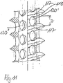
骨の欠損、特に骨粗鬆症による骨折を治療するための公知の治療法は、骨セメントおよび/または医用の活性物質、特に成長促進物質を骨に注入することを含む。これは、特に脊柱の領域においては、椎骨に注入すべき物質を正確に位置決めする必要がある。さらに多くの場合、その上、欠損のある椎骨を安定させ、これらを互いに対して固定する必要がある。 Known therapies for treating bone defects, in particular fractures due to osteoporosis, include injecting bone cement and / or medical active substances, in particular growth promoting substances, into the bone. This requires accurate positioning of the material to be injected into the vertebrae, especially in the spinal column region. More often, it is also necessary to stabilize the defective vertebrae and fix them relative to each other.
DE 100 55 891 A1は、骨ねじ山を有する管状ねじ山部分と、ねじ山部分の壁に設けられた複数の開口部とを備えた骨ねじを開示する。 DE 100 55 891 A1 discloses a bone screw comprising a tubular thread part having a bone thread and a plurality of openings provided in the wall of the thread part.
この発明の目的は、導入部分に記載される種類の固定要素を特に骨粗鬆症による骨折の治療で用いることができるように改善することである。 The object of the present invention is to improve a fixing element of the type described in the introduction part so that it can be used in particular in the treatment of fractures due to osteoporosis.
この目的は請求項1に特徴付けられる固定要素によって達成される。このようにして、骨ねじは周囲の骨物質と融合することが可能であり、同時に骨部分または椎骨を互いに対して位置決めしかつ固定することができる。さらに、骨に導入すべき物質を所望の部位に正確に導入することができる。さらに、このような固定要素のために、請求項15にクレームされるシャンク要素を用いることができる。
This object is achieved by a fixing element characterized in claim 1. In this way, the bone screw can be fused with the surrounding bone material and at the same time bone parts or vertebrae can be positioned and fixed relative to each other. Furthermore, the substance to be introduced into the bone can be accurately introduced at a desired site. Furthermore, a shank element as claimed in
この発明の展開例は従属請求項において特徴付けられる。 Developments of the invention are characterized in the dependent claims.
この発明のさらなる特徴および詳細は、添付の図面に関連して具体的な実施例の説明で述べられる。 Additional features and details of the present invention are set forth in the description of specific embodiments in connection with the accompanying drawings.
図1および図2に示される第1の実施例では、固定要素は、第1の端部2と反対側の第2の端部3とを備えた円筒形の受部1を有する。2つの端部は、対称軸または長手方向軸4に対して垂直に延在する。長手方向軸4に対して同軸に、第1の端部2から、第2の端部3からの予め定められた距離まで延在する第1の同軸ボア5が設けられる。第2の端部3に第2のボア6が設けられ、その直径は第1のボアの直径よりも小さい。図示される実施例では、第2のボアは開口部として設計され、その端縁は中空の球体セグメントとして形作られ、その中間点は第1の端部2の方に方向付けられる。
In the first embodiment shown in FIGS. 1 and 2, the fixing element has a cylindrical receiving part 1 with a
受部1は、第1の端部2から始まり、長手方向軸3に対して垂直に延在し、第1の端部2に向かって終端となる2つの自由脚8および9を備えた、U字型の窪み7を有する。第
1の端部2に隣接して、枝部が内面ねじ山10を有する。内面ねじ山は、たとえば、ねじ山フランクがいずれの場合も対称軸4に対して90°の角度で延在する平坦なねじ山として設計される。U字型の窪みの底部は、第2の端部3から予め定められた距離まで延在する。
The receiving part 1 comprises two
受部1と協働するねじ12は、ねじ山部分を備えたねじシャンク13を有し、図2に示される組立てられた状態でねじシャンクに接続される球体のセグメント状の頭部14を有し、また先端部15を有する。
The screw 12 cooperating with the receiving part 1 has a
ねじシャンク13は管状に設計され、頭部14の方に向けられた第1の端部16と、この端部16から遠い端部17とを有する。管状ねじシャンク13はその壁に複数の窪み18を有し、これら複数の窪み18は図示される実施例では菱型である。この菱型は、ここでは、いずれの場合も対称軸が管の対称軸と平行に延在するように方向付けられる。窪み18は、開口部が、円周方向に配置された前列の開口部の開口部間に存在するように、軸方向に互いにずらされる。外壁上には、ねじシャンク13の第2の端部17から、第1の端部16からの少なくとも予め定められた距離まで延在する領域においていわゆる骨ねじ山19があり、この骨ねじ山19の形状は従来の骨ねじの骨ねじ山に対応する。図示される実施例では、管状ねじシャンク13はまた、第1の端部16に隣接して部分20を有し、ここには骨ねじ山19が形成されず、その面は主として滑らかである。さらに、ねじを骨にねじ込むために、ねじ回しのためのスリット21が第1の端部16に設けられる。
The
先端部15は先端部分自体とさらにシャンク22とを含み、このシャンク22は図示される例示的な実施例ではメートル外面ねじ山を有する。第2の端部17に隣接して、管状ねじシャンク13は、その内壁上に、対応するメートル内面ねじ山を備えた部分を有し、組立てられた状態では、その先端部は管状ねじシャンクにしっかりとねじ込まれる。
The
図1から最もよく分かるように、頭部14は、受部1の第1の端部2の方に向けられるべき端部が平らにされた球体として設計され、長手方向軸4に対して同軸に延在する第1のボア23を有し、その直径は管状ねじシャンク13の直径よりも小さい。同軸の第2のボア24がまた設けられ、組立てられた状態で受部の第2の端部3の方に向けられた頭部14のその端部から予め定められた距離だけ頭部の中に延在し、その直径は管状ねじシャンク13の部分20における外径と等しく、このため、ねじシャンクの部分20を押込んで摩擦によってボア24に嵌合させることができる。図1から分かるように、こうして中空の球体のセグメントとして形作られた頭部14は、平らにされた端部から遠い側に切抜き部25を備える。切抜き部25は円周方向に互いから離れて配置され、長手方向軸4と平行に延在し、平らにされた側から遠い端部にまで延びる。このようにして、組立てられた状態の受部の第1の端部2から遠い方に向けられた端部26は、ねじシャンク13を挿入可能にするために弾力的に外側に曲がり得るように設計される。
As best seen in FIG. 1, the
円筒形に設計された圧力要素30がまた設けられ、その外径は、ちょうどこの圧力要素を第1のボア5に挿入しかつここで軸方向に往復して動かすことができるような大きさである。圧力要素30は、第2の端部3の方に向けられたその下側に中空の球体セグメントとして形作られた部分31を有し、この部分31は長手方向軸4と対称的であり、その半径は頭部14の半径に対応する。圧力要素はまた、長手方向軸4に対して横方向に延在するU字型の窪み32を有し、その自由脚は第1の端部2の方に延在し、ロッド40を受けるべきチャネルを形成する。U字型の窪みの深さは、挿入すべきロッド40の直径よりも大きいので、組立てられた状態では、圧力要素30の脚は挿入されたロッド40の上方に突き出る。U字型の窪み32の底部には、ねじ込み工具と係合するのに用いられる同軸ボア33がある。
A cylindrically designed
受部1に対して、挿入されたねじシャンク13とともに頭部14の位置を固定するために、ナット50を受部の脚8と脚9との間にねじ込むことができ、上述のナット50は脚の内面ねじ山11と協働する外面ねじ山51を備える。このナットは、一方端にねじ込み工具と係合するためのスリット52を有する。
In order to fix the position of the
ナット50にねじ込むための内面ねじ60をまた備え、この内面ねじ60はナット50の内面ねじ山と協働する外面ねじ山を有する。内面ねじ60はねじ込み工具と係合するための窪み61を有する。
An internal thread 60 for screwing into the nut 50 is also provided, and the internal thread 60 has an external thread that cooperates with the internal thread of the nut 50. The internal screw 60 has a
使用する際に、ねじ12は最初に骨または椎骨にねじ込まれる。次いで、骨セメントまたは別の充填剤および/もしくは活性物質が注射器を介して管状シャンクに注入される。次いで、受部1は第2のボア6をシャンク13の上にして配置され、頭部14は第1の端部2の方向からシャンク13上に案内され、このため、シャンク13は、骨がねじ切りされないその部分20を介してボア24に挿入され、頭部は図2に示される態様でシャンクを囲む。頭部14およびシャンク13は摩擦による嵌合で互いに接続される。次いで、圧力要素30が嵌め合わされ、ねじ込まれているナット50によってスリット25を備えた頭部14上に押込まれ、このため上述の頭部14はシャンク13にしっかりと接続されるかまたは締付けられ、同時に受部における中空の球体セグメントに押当てられ、こうしてその回転位置で固定される。ロッド40は依然として自由にずらすことが可能である。次いで上述のロッド40が、ねじ込まれている内面ねじ60によって固定される。こうして固定要素は、活性物質でもって、および/または周囲の骨物質との融合による安定化でもって、同時にロッドにより骨片または椎骨を位置決めしかつ固定して、欠損のある骨の治療を可能にする。
In use, the screw 12 is first screwed into the bone or vertebra. Bone cement or another filler and / or active substance is then injected into the tubular shank via a syringe. The receiving part 1 is then placed with the second bore 6 on the
図3に示される変形例は、頭部14のボア24の内壁が円周方向に波形27を備えるように設計され、かつシャンク13の部分20が対応する波形27′を備えるという点で、図1および図2に示される実施例とは異なる。
The variant shown in FIG. 3 is illustrated in that the inner wall of the
図4に示される変形例では、頭部14およびシャンク13は、シャンクを頭部にねじ込むことができるように、波形ではなく適合するねじ山28および28′を有する。
In the variant shown in FIG. 4,
ねじシャンク13はまた、これを骨にねじ込むための他の手段も有し得る。たとえば、ねじシャンク13はまたその第1の端部に隣接する内面ねじ山を有してもよく、または軸の全長にわたって延在する内面ねじ山を有してもよい。この場合、シャンクは、中にねじ込まれかつねじ込み後に再び取外される頭部または他の補助機器を介して所定の位置にねじ込まれ得る。代替的には、ねじシャンク13はその第1の端部に隣接して、アレンキー(Allen key)と係合するための内面の六角形を有することが可能である。
The
ねじ込む前にねじシャンク13に骨物質を充填することも可能であり、この骨物質は、ねじ込み後にねじを囲む骨物質と融合する。
It is also possible to fill the
図5および図6に示される実施例は、主としてねじ頭部140の設計およびねじシャンク13へのその接続の点で、図1および図2に示される実施例とは異なる。
The embodiment shown in FIGS. 5 and 6 differs from the embodiment shown in FIGS. 1 and 2 mainly in the design of the screw head 140 and its connection to the
ねじ頭部140は球体のセグメント状に設計され、その球体半径は、中空の球体セグメントとして形作られる受部の部分の半径と実質的に等しい。頭部はまた、受部1の第1の端部2の方に向けられるべきその平らな端部に、ねじ回しと係合するための窪み141を有する。その反対側の端部に、ねじ頭部140は、管状ねじシャンク13の外径に対応する外径を有する円筒形の首142を有する。この首から、外面ねじ山を備えた突起143が延在し、これによりねじ頭部を管状ねじシャンク13にねじ込むことができ、この目的
のために管状ねじシャンク13は、その第1の端部16に隣接してその内壁上に内面ねじ山131を有する。こうして、第1の実施例と対照的に、頭部はシャンクにおいて係合する頭部によってねじシャンクに接続されるが、第1の実施例では頭部はシャンクを囲んで係合する。
The screw head 140 is designed in the shape of a sphere segment, the sphere radius of which is substantially equal to the radius of the part of the receiving part which is shaped as a hollow sphere segment. The head also has a
この実施例では、ねじ頭部140は、その中を通りかつ活性物質の導入のためにチャネルとしての役割りを果たす同軸ボア(図示せず)を便宜上有し得る。 In this embodiment, the screw head 140 may conveniently have a coaxial bore (not shown) that passes through it and serves as a channel for the introduction of the active substance.
第1の実施例におけるように、管状ねじシャンク13の第2の端部17に隣接する内壁は、同様に、先端部15がねじ込まれる内面ねじ山を備える。また第1の実施例と同様に、内面ねじ山は管状ねじシャンクの全長に沿って形成されてもよく、これは製造技術の観点から好ましく、加えて、管状ねじシャンクを所望の長さにまで短くすることを可能にする。スリット132が、ねじ回しとの係合のためにねじシャンク13の第1の端部に設けられてもよい。
As in the first embodiment, the inner wall adjacent to the second end 17 of the
図示される例示的な実施例には、第1の実施例に示される頭部/ロッド固定の変形例が示される。第1の実施例の圧力要素50と対照的に、圧力要素150は、挿入されるロッド40の上方で横方向に突き出ない短い脚151および152しか有さない。そうでない場合、圧力要素は、第1の実施例と同様に、頭部の方に向けられた側に球体の凹部153と、同軸ボア154とを有する。
In the illustrated exemplary embodiment, a variation of the head / rod fixation shown in the first embodiment is shown. In contrast to the pressure element 50 of the first embodiment, the
頭部およびロッドを固定するために内面ねじ160が備えられ、この内面ねじ160は、受部の脚の内面ねじ山に対応する外面ねじ山161と、ねじ回しと係合するための窪みとを有する。確実に固定するために、受部1にねじ留めすることのできるロックナット170を備える。
An
使用する際に、先端部が最初にねじシャンク13にねじ留めされる。次いで、必要であれば骨物質が管状ねじシャンクに導入され、頭部140がねじ留めされる。すべて一緒にねじ込まれるシャンク13、先端部15および頭部140を含むねじが、次いで、公知の多軸ねじのように受部1に導入され、骨にねじ込まれる。カニューレ状の頭部140を用いる場合、活性物質または充填剤を注入することによって導入できる。最後に、圧力要素が嵌め合わされ、受部が、内面ねじ160およびロックナット170をねじ込むことによりロッドにしっかりと接続され、こうして受部における頭部の角度位置が固定される。
In use, the tip is first screwed onto the
代替的には、ねじシャンクがねじ回しとの係合のためのスリット132を有する場合、ねじ留め式の先端部15を備えたねじシャンク13を頭部140なしで最初にねじ込むことも可能である。次いで活性物質を導入し、受部を嵌め合せ、ねじ頭部をねじ留めすることができる。次いで、ロッドへの接続を上述のとおりに行なう。
Alternatively, if the screw shank has a slit 132 for engagement with a screwdriver, the
記載された実施例の変形が可能である。一方では、頭部およびロッドの固定は記載された変形例に限定されない。第2の実施例における頭部およびロッドの固定は第1の実施例でも用いることができ、逆の場合も同様である。さらに、たとえばロッドに作用する内面ねじだけを備える他の構成例も提供することができる。 Variations of the described embodiment are possible. On the other hand, the fixing of the head and the rod is not limited to the described variant. The fixing of the head and rod in the second embodiment can also be used in the first embodiment, and vice versa. In addition, other configuration examples can be provided, for example with only internal threads acting on the rod.
ねじシャンクにおける菱型の開口部ではなく、円形の開口部、楕円形の開口部または所望のいずれかの形状の他の開口部を設けることも可能である。開口部はまた、ねじシャンクの軸の全長にわたって延在し得る。 Instead of a diamond-shaped opening in the screw shank, it is also possible to provide a circular opening, an elliptical opening or any other opening of any desired shape. The opening may also extend over the entire length of the shaft of the screw shank.
第1の実施例における頭部14は、一箇所で軸方向に途切れなくスロットを付けられ得る。こうして得られる弾性は、頭部がわずかに加圧され得、このため受部の第2の端部3
の方から導入され得ることを意味する。
The
Means that it can be introduced from
先端部15はセルフタッピング設計であり得る。さらに、先端部は、活性物質が通過するための、同軸に延在する連続したチャネルを有し得る。
The
管状ねじシャンク13は特定の適用例に好適な長さであり得、上述の長さは、適切な場合、より長い管部分から所望の長さの管部分を切断することにより得られ、また直径は適用例に対応する。特に、ねじはまた茎状ねじとして設計されてもよい。
脊柱または骨を安定させるために、この発明に従った固定要素は一般的にロッドによって公知の固定要素と組合され得る。 In order to stabilize the spine or bone, the anchoring elements according to the invention can be combined with known anchoring elements generally by means of rods.
図7a)および図7b)に示される例示的な実施例では、ロッド40への多軸接続は、先述の例におけるようにねじ軸の方向には行なわれず、代わりに、ねじ軸に対して横方向にオフセットされる。
In the exemplary embodiment shown in FIGS. 7a) and 7b), the multiaxial connection to the
図7a)に従った固定要素は、管状ねじシャンク13、先端部、および球体のセグメントとして形作られる頭部140を含むねじ要素を含み、頭部140を受ける2つの部分からなるホルダ70をさらに含み、下方部分71はねじシャンクの方に向けられ、上方部分72はねじシャンクから遠い方に向けられ、これらの部分はともにロッド40を囲む。下方部分71および上方部分72は同一に設計され、互いに対して鏡面対称で配置される。これらは各々、内面ねじ山を備えた中心ボア73および74を有し、それぞれの他方部分71および72から遠い方に向けられる面上に皿穴ボアを有する。ボア73および74の側に、そこから離れて、円筒形セグメント状の窪み75および76を設け、これら窪み75および76はそれぞれの他方部分71および72に面し、ロッド40を把持するために用いられる。ボア73および74の他方側に対し、下方部分71および上方部分72は、それぞれの他方部分の方に向けられた側に、ねじ頭部40を把持するための球体のセグメントとして形作られる窪み77および78を有する。他方部分71および72から遠い方に向けられる面上で、窪み77および78は外側に広がる窪み79および80によって同軸に隣接する。
The fixing element according to FIG. 7 a) comprises a screw element comprising a
ホルダの下方部分71および上方部分72はねじ81によって互いに接続される。このねじ81は、上方部分の内面ねじ山に導入され得かつ下方部分の内面ねじ山にねじ込まれ得る。ねじ81は、上方部分72を通って案内される部分における直径が上方部分の内面ねじ山の直径よりも小さく、下方部分を通って案内される部分には下方部分の内面ねじ山と協働する外面ねじ山を有する。円筒形セグメントとして形作られた窪み75および76ならびに球体セグメントとして形作られた窪み77および78は、ロッド40および頭部140を把持する状態において下方部分71および上方部分72が互いに対して平行に方向付けられかつ互いから間隔を空けられるように、寸法決めされかつ互いに対して配置される。
The lower part 71 and the
使用する際に、ねじ要素は、最初に先端部および頭部140をシャンクにねじ留めすることにより組立てられる。ホルダの上方部分および下方部分はねじ81を緩めることにより互いに対して90°回転され、これによりねじ要素を下方部分に導入することができる。ねじ要素は、その頭部140が下方部分71の球体セグメント状の窪み77に位置するまで導入される。次いで、これが骨にねじ込まれる。次に、ロッド40が挿入され、上方部分72を90°回転させてロッドを把持する。ホルダにおけるねじ頭部140の角度位置およびロッドの位置を設定した後、この構成が、ねじ81を締めることにより固定される。
In use, the screw element is assembled by first screwing the tip and head 140 into the shank. The upper and lower parts of the holder are rotated 90 ° relative to each other by loosening the
インプラントは、骨盤および長骨の骨折を固定するのに特に好適である。 The implant is particularly suitable for fixing pelvic and long bone fractures.
図7b)に示される実施例は、ホルダ70′が2つのロッド40および40′を把持するために本質的に対称的に設計された下方部分71′および上方部分72′を有するという点で、図7a)に示される実施例とは異なる。下方部分71′および上方部分72′は、この場合、ロッド40および40′の中心線ならびにねじの球体セグメント状の頭部140の中心点によって規定される面に対して対称に設計され、これらは各々2つのボア73および73′ならびに74および74′をそれぞれ有し、かつ2つの円筒形セグメント状の窪み75および75′ならびに76および76′をそれぞれ有する。これらを固定するために、2つの固定ねじ81および81′を設ける。この動作は上述の例示的な実施例に類似しており、唯一の違いは2つのロッドが固定されるべきである点である。
The embodiment shown in FIG. 7b) is that the holder 70 'has a lower part 71' and an upper part 72 'designed essentially symmetrically for gripping the two
図8に示される実施例では、固定要素は、管状ねじシャンク13およびこれに接続される先端部によって形成されるねじ要素と、ねじ要素に単軸に接続することができかつロッド40を受ける受部90とを含む。受部90は実質的に円筒形であり、断面がU字型の窪み91を有し、この窪み91は、ちょうどロッド40が挿入され得かつ窪みの底部に嵌合するような寸法にされる。2つの自由脚92および93がU字型の窪み91によって形成される。自由端に隣接して、枝部92および93は内面ねじ山94を有し、この内面ねじ山94は、ロッド40を固定するためにこれらの脚の間にねじ込まれるべき内面ねじ95の対応する外面ねじ山と協働する。受部90は、自由端から遠い方に向けられたその端部に、管状シャンク13にねじ込むためのねじ切りされた軸96を有する。
In the embodiment shown in FIG. 8, the fixing element comprises a screw element formed by a
使用の際に、固定要素全体が好ましくは最初に組立てられ、必要な場合、管状シャンクに活性物質または骨物質が充填される。次いで、固定要素は公知の単軸ねじのように骨にねじ込まれる。次いで、ロッドによって1つ以上の他の固定要素への接続がなされる。正確な位置において、ロッドは次に内面ねじによって固定される。 In use, the entire fixation element is preferably assembled first, and if necessary, the tubular shank is filled with active or bone material. The fixation element is then screwed into the bone like a known uniaxial screw. The rod is then connected to one or more other fixing elements. In the correct position, the rod is then secured by internal threads.
図1から図8に示される実施例では、窪み18のうちいくつかは、骨ねじ山の螺旋状の頂部を中断するように配置される。こうして歯または鋭い端部が骨ねじ山上に形成される。この歯または鋭い端部は、上述の要素が骨にねじ込まれているとフライス削りの効果を及ぼす。しかしながら、あるいくつかの適用例に対しては、滑らかなねじ込みが所望されるかまたは必要とされる。
In the embodiment shown in FIGS. 1-8, some of the
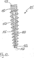
この種類の適用例に対しては、図9〜図11に示される管状ねじシャンクの変形例が有利である。管状ねじシャンク113は、第1の端部114と、これから遠い方の第2の端部115とを備えた円筒形の管を含む。図1〜図8の実施例において既に分かるように、管の外壁は、骨にねじ込むための骨ねじ山を備えた骨ねじ山部分116を有する。骨ねじ山はセルフタッピングねじ山として設計され、公知の態様では、ねじ山フランク117、螺旋状の頂部118、幅Bのねじ山谷底119およびねじ山ピッチPを有する。少なくとも骨ねじ山部分116においては、管状シャンクの壁は、断面が円形である複数の窪み120を有する。これら窪み120は各々の場合それらの中心がねじ山谷底119に位置するように構成され、各窪み120の直径Dはねじ山ピッチPより小さく、特にねじ山谷底の幅Bよりも大きくないので、図9および図10に示される例示的な実施例においては、窪み120は全体がねじ山谷底119に位置し、フランク117には延在しない。ねじのひと巻ごとのねじ山谷底119において、複数の窪み120が螺旋状の線上に均一に間隔を空けて設けられるので、軸方向にみると、ねじのひと巻きの窪みはその下方にあるねじのひと巻きの窪みの上方に位置する。
For this type of application, the modification of the tubular thread shank shown in FIGS. 9 to 11 is advantageous.
図9から特に分かるように、管状シャンク113は、第1の端部115に隣接して、骨ねじ山を有さず、かつ窪みが形成されない滑らかな外壁を有する、部分121を有する。
さらに、図示される例示的な実施例では、内面ねじ山部分122が第1の端部114および第2の端部115に隣接して形成され、上述の内面ねじ山部分122は、先端部、ならびにねじ頭部および受部にそれぞれ接続するのに役立ち、これは先述の実施例に関連して記載されている通りである。
As can be seen in particular from FIG. 9, the
Further, in the illustrated exemplary embodiment, an
図11に示される他の変形された実施例は、窪み120′の直径D′がねじ山谷底119の幅Bよりも大きいので、窪み120′が骨ねじ山のフランク117に延在するが螺旋状の頂部118を中断しないという点で、図9および図10に示される実施例とは異なる。このようにして、骨とより良好に融合させるために窪みをより大きくすることが可能であるが、ねじ込み中にフライス削り作用を有する刃を形成することが避けられる。というのも、ねじ山の頂部が損なわれないままにされるからである。
Another modified embodiment shown in FIG. 11 is that the
別の変形例(図示せず)では、窪み120および120′のすべてまたはこれらのうちいくつかが、面粗さを形成してより融合し易くする皿穴を備えて壁の外側に設けられる。しかしながら、ねじ軸方向のこの皿穴の直径がねじ山ピッチPよりも小さいので、螺旋状の頂部118は損なわれないままにされる。
In another variation (not shown), all or some of the
別の変形例では、窪みは楕円形または菱型である。重要なことは、これらがねじ山谷底に配置され、かつ骨ねじ山の頂部を損なわないような寸法であることである。さらに、ねじのひと巻きごとに窪みを設ける必要はない。 In another variation, the depression is oval or diamond shaped. What is important is that they are dimensioned so that they are located at the bottom of the thread valley and do not damage the top of the bone thread. Furthermore, it is not necessary to provide a recess for each turn of the screw.
別の変形例では、骨ねじ山部分116はシャンク113の全長に延在する。内面ねじ山122も同様にその全長に延在し得る。代替的には、内面ねじ山122はまた、一方端に一部分だけに設けられてもよいかまたはすべて省略されてもよい。内面ねじ山を設けない場合、固定要素の他の部分への接続は、たとえば滑り嵌めによって達成される。
In another variation, the bone thread portion 116 extends the entire length of the
図12に示されるシャンクの別の変形された実施例では、管状ねじシャンク125は全体が円筒形には設計されないが、先端部に接続されるべき端部127に向かってテーパ状をなす円錐形の骨ねじ山部分126を有する。円錐形の骨ねじ山部分126に隣接しかつ対向する端部127および128にまで延在して、内面ねじ山を備えた円筒形部分129および130がいずれの場合にもあり、一方端は先端部に接続され、他方端は頭部または受部に接続される。これは上述される通りである。
In another modified embodiment of the shank shown in FIG. 12, the
この変形例では、先端部に接続されるべき円筒形部分129が設けられず、代わりに、円錐形の骨ねじ山部分126自体の自由端が先端部としての役割を果たす。
In this variant, the
図12に示される実施例では、図9〜図11に示される実施例と同様に、ねじ山谷底上に窪み120が設けられる。別の変形例では、図1〜図8に示される管状シャンク13の少なくとも一部分が同様に円錐形にされる。
In the embodiment shown in FIG. 12, a
Claims (10)
前記ねじをロッド型の要素(40)に接続するための一体化された受部(1)を含み、
前記ねじおよび前記受部は互いに接続され、前記ねじの前記シャンク(13)は管状に設計され、その壁は複数の開口(18)を有し、
前記シャンク(13)および前記頭部(14;140)は別個の部分として設計され、
前記シャンク(13)の前記壁自体の、前記頭部の側の第1の端部(16)には、前記ねじを骨にねじ込むためのねじ回しが係合する手段(21)が形成され、
前記壁の前記第1の端部とは反対側の第2の端部(17)は、前記ねじの先端部となる、個別の要素からなる先端部材(15)を受け入れる構造を有し、
前記頭部(14)は、前記シャンクの方に向けられたその端部に、前記シャンク(13)が把持される窪み(24)を有するとともに、弾力的に曲がる端縁(25,26)を有し、
前記シャンク(13)は、前記頭部(14)の方に向けられるその端部に隣接して、骨ねじ山のない部分(20)を有し、
前記骨ねじ山のない部分(20)は滑らかな外面を有する、固定要素。A fixation element comprising a shank (13) with a bone thread portion and a screw (12) having a head (14; 140),
An integrated receiver (1) for connecting the screw to a rod-shaped element (40);
The screw and the receiving part are connected to each other, the shank (13) of the screw is designed to be tubular, its wall has a plurality of openings (18);
The shank (13) and the head (14; 140) are designed as separate parts;
On the first end (16) on the head side of the wall itself of the shank (13) is formed means (21) for engaging a screwdriver for screwing the screw into the bone,
A second end opposite to the first end portion of said wall (17) is a tip portion of the screw, have a structure to accept the tip member (15) consisting of individual elements,
The head (14) has a recess (24) in which the shank (13) is gripped at its end directed towards the shank and has elastically bent edges (25, 26). Have
The shank (13) has a bone screw free part (20) adjacent to its end directed towards the head (14),
The anchoring element, wherein said bone screw free part (20) has a smooth outer surface .
前記ねじをロッド型の要素(40)に接続するための一体化された受部(1)を含み、
前記ねじおよび前記受部は互いに接続され、前記ねじの前記シャンク(13)は管状に設計され、その壁は複数の開口(18)を有し、
前記シャンク(13)および前記頭部(14;140)は別個の部分として設計され、
前記シャンク(13)の前記壁自体の、前記頭部の側の第1の端部(16)には、前記ねじを骨にねじ込むためのねじ回しが係合する手段(21)が形成され、
前記壁の前記第1の端部とは反対側の第2の端部(17)は、前記ねじの先端部となる、個別の要素からなる先端部材(15)を受け入れる構造を有し、
前記頭部(14)は、前記シャンクの方に向けられたその端部に、前記シャンク(13
)が把持される窪み(24)を有するとともに、弾力的に曲がる端縁(25,26)を有し、
前記シャンク(13)は、前記頭部(14)の方に向けられるその端部に隣接して、骨ねじ山のない部分(20)を有し、
前記骨ねじ山のない部分(20)は前記窪み(24)の波形の壁(27)と協働する波形の外面(27′)を有する、固定要素。A fixation element comprising a shank (13) with a bone thread portion and a screw (12) having a head (14; 140),
An integrated receiver (1) for connecting the screw to a rod-shaped element (40);
The screw and the receiving part are connected to each other, the shank (13) of the screw is designed to be tubular, its wall has a plurality of openings (18);
The shank (13) and the head (14; 140) are designed as separate parts;
On the first end (16) on the head side of the wall itself of the shank (13) is formed means (21) for engaging a screwdriver for screwing the screw into the bone,
A second end opposite to the first end portion of said wall (17) is a tip portion of the screw, have a structure to accept the tip member (15) consisting of individual elements,
Said head (14) is at its end directed towards said shank, said shank (13).
) Has a recess (24) to be gripped, and has elastically bent edges (25, 26),
The shank (13) has a bone screw free part (20) adjacent to its end directed towards the head (14),
Fixing element, wherein said bone screw free part (20) has a corrugated outer surface (27 ') cooperating with a corrugated wall (27) of said recess (24) .
Applications Claiming Priority (2)
| Application Number | Priority Date | Filing Date | Title |
|---|---|---|---|
| DE10246177A DE10246177A1 (en) | 2002-10-02 | 2002-10-02 | Anchor element consists of screw with head, bone-thread section on shank and holder joining rod-shaped part to screw. with cavities in wall, and thread-free end of shank |
| PCT/EP2002/014676 WO2004032774A1 (en) | 2002-10-02 | 2002-12-20 | Bone anchoring element |
Related Child Applications (1)
| Application Number | Title | Priority Date | Filing Date |
|---|---|---|---|
| JP2009210882A Division JP5138648B2 (en) | 2002-10-02 | 2009-09-11 | Fixed element |
Publications (3)
| Publication Number | Publication Date |
|---|---|
| JP2006501908A JP2006501908A (en) | 2006-01-19 |
| JP2006501908A5 JP2006501908A5 (en) | 2006-03-02 |
| JP4437086B2 true JP4437086B2 (en) | 2010-03-24 |
Family
ID=37252235
Family Applications (2)
| Application Number | Title | Priority Date | Filing Date |
|---|---|---|---|
| JP2004542245A Expired - Lifetime JP4437086B2 (en) | 2002-10-02 | 2002-12-20 | Fixed element |
| JP2009210882A Expired - Lifetime JP5138648B2 (en) | 2002-10-02 | 2009-09-11 | Fixed element |
Family Applications After (1)
| Application Number | Title | Priority Date | Filing Date |
|---|---|---|---|
| JP2009210882A Expired - Lifetime JP5138648B2 (en) | 2002-10-02 | 2009-09-11 | Fixed element |
Country Status (7)
| Country | Link |
|---|---|
| US (1) | US9848892B2 (en) |
| EP (2) | EP1681024B1 (en) |
| JP (2) | JP4437086B2 (en) |
| KR (1) | KR100996240B1 (en) |
| AU (1) | AU2002360070A1 (en) |
| DE (3) | DE10246177A1 (en) |
| WO (1) | WO2004032774A1 (en) |
Families Citing this family (217)
| Publication number | Priority date | Publication date | Assignee | Title |
|---|---|---|---|---|
| US20060025771A1 (en) * | 2000-08-23 | 2006-02-02 | Jackson Roger P | Helical reverse angle guide and advancement structure with break-off extensions |
| US7837716B2 (en) * | 2000-08-23 | 2010-11-23 | Jackson Roger P | Threadform for medical implant closure |
| US20060083603A1 (en) * | 2000-08-23 | 2006-04-20 | Jackson Roger P | Reverse angled threadform with anti-splay clearance |
| US7833250B2 (en) | 2004-11-10 | 2010-11-16 | Jackson Roger P | Polyaxial bone screw with helically wound capture connection |
| US8377100B2 (en) * | 2000-12-08 | 2013-02-19 | Roger P. Jackson | Closure for open-headed medical implant |
| US6726689B2 (en) * | 2002-09-06 | 2004-04-27 | Roger P. Jackson | Helical interlocking mating guide and advancement structure |
| US8292926B2 (en) | 2005-09-30 | 2012-10-23 | Jackson Roger P | Dynamic stabilization connecting member with elastic core and outer sleeve |
| US10258382B2 (en) | 2007-01-18 | 2019-04-16 | Roger P. Jackson | Rod-cord dynamic connection assemblies with slidable bone anchor attachment members along the cord |
| US10729469B2 (en) | 2006-01-09 | 2020-08-04 | Roger P. Jackson | Flexible spinal stabilization assembly with spacer having off-axis core member |
| US7862587B2 (en) | 2004-02-27 | 2011-01-04 | Jackson Roger P | Dynamic stabilization assemblies, tool set and method |
| US8353932B2 (en) | 2005-09-30 | 2013-01-15 | Jackson Roger P | Polyaxial bone anchor assembly with one-piece closure, pressure insert and plastic elongate member |
| US6740086B2 (en) | 2002-04-18 | 2004-05-25 | Spinal Innovations, Llc | Screw and rod fixation assembly and device |
| US8282673B2 (en) * | 2002-09-06 | 2012-10-09 | Jackson Roger P | Anti-splay medical implant closure with multi-surface removal aperture |
| US8257402B2 (en) * | 2002-09-06 | 2012-09-04 | Jackson Roger P | Closure for rod receiving orthopedic implant having left handed thread removal |
| US8876868B2 (en) * | 2002-09-06 | 2014-11-04 | Roger P. Jackson | Helical guide and advancement flange with radially loaded lip |
| US20060009773A1 (en) * | 2002-09-06 | 2006-01-12 | Jackson Roger P | Helical interlocking mating guide and advancement structure |
| DE10260222B4 (en) * | 2002-12-20 | 2008-01-03 | Biedermann Motech Gmbh | Tubular element for an implant and implant to be used in spine or bone surgery with such an element |
| US8540753B2 (en) | 2003-04-09 | 2013-09-24 | Roger P. Jackson | Polyaxial bone screw with uploaded threaded shank and method of assembly and use |
| US7621918B2 (en) | 2004-11-23 | 2009-11-24 | Jackson Roger P | Spinal fixation tool set and method |
| US6716214B1 (en) * | 2003-06-18 | 2004-04-06 | Roger P. Jackson | Polyaxial bone screw with spline capture connection |
| US7354442B2 (en) * | 2003-05-05 | 2008-04-08 | Warsaw Orthopedic, Inc. | Bone anchor and methods of using the same |
| US7377923B2 (en) * | 2003-05-22 | 2008-05-27 | Alphatec Spine, Inc. | Variable angle spinal screw assembly |
| US8936623B2 (en) | 2003-06-18 | 2015-01-20 | Roger P. Jackson | Polyaxial bone screw assembly |
| US8257398B2 (en) | 2003-06-18 | 2012-09-04 | Jackson Roger P | Polyaxial bone screw with cam capture |
| US8814911B2 (en) | 2003-06-18 | 2014-08-26 | Roger P. Jackson | Polyaxial bone screw with cam connection and lock and release insert |
| US8092500B2 (en) | 2007-05-01 | 2012-01-10 | Jackson Roger P | Dynamic stabilization connecting member with floating core, compression spacer and over-mold |
| US8398682B2 (en) | 2003-06-18 | 2013-03-19 | Roger P. Jackson | Polyaxial bone screw assembly |
| US7967850B2 (en) * | 2003-06-18 | 2011-06-28 | Jackson Roger P | Polyaxial bone anchor with helical capture connection, insert and dual locking assembly |
| US8137386B2 (en) | 2003-08-28 | 2012-03-20 | Jackson Roger P | Polyaxial bone screw apparatus |
| US7776067B2 (en) | 2005-05-27 | 2010-08-17 | Jackson Roger P | Polyaxial bone screw with shank articulation pressure insert and method |
| US8366753B2 (en) * | 2003-06-18 | 2013-02-05 | Jackson Roger P | Polyaxial bone screw assembly with fixed retaining structure |
| US7766915B2 (en) | 2004-02-27 | 2010-08-03 | Jackson Roger P | Dynamic fixation assemblies with inner core and outer coil-like member |
| US8377102B2 (en) | 2003-06-18 | 2013-02-19 | Roger P. Jackson | Polyaxial bone anchor with spline capture connection and lower pressure insert |
| US11419642B2 (en) | 2003-12-16 | 2022-08-23 | Medos International Sarl | Percutaneous access devices and bone anchor assemblies |
| US7179261B2 (en) | 2003-12-16 | 2007-02-20 | Depuy Spine, Inc. | Percutaneous access devices and bone anchor assemblies |
| US7527638B2 (en) | 2003-12-16 | 2009-05-05 | Depuy Spine, Inc. | Methods and devices for minimally invasive spinal fixation element placement |
| US8152810B2 (en) | 2004-11-23 | 2012-04-10 | Jackson Roger P | Spinal fixation tool set and method |
| US11241261B2 (en) | 2005-09-30 | 2022-02-08 | Roger P Jackson | Apparatus and method for soft spinal stabilization using a tensionable cord and releasable end structure |
| AU2004317551B2 (en) | 2004-02-27 | 2008-12-04 | Roger P. Jackson | Orthopedic implant rod reduction tool set and method |
| US7160300B2 (en) | 2004-02-27 | 2007-01-09 | Jackson Roger P | Orthopedic implant rod reduction tool set and method |
| US9050148B2 (en) | 2004-02-27 | 2015-06-09 | Roger P. Jackson | Spinal fixation tool attachment structure |
| US7503924B2 (en) * | 2004-04-08 | 2009-03-17 | Globus Medical, Inc. | Polyaxial screw |
| US8475495B2 (en) | 2004-04-08 | 2013-07-02 | Globus Medical | Polyaxial screw |
| US8728132B2 (en) | 2004-04-20 | 2014-05-20 | James L. Chappuis | Internal pedicle insulator apparatus and method of use |
| US20180228621A1 (en) | 2004-08-09 | 2018-08-16 | Mark A. Reiley | Apparatus, systems, and methods for the fixation or fusion of bone |
| US7186255B2 (en) * | 2004-08-12 | 2007-03-06 | Atlas Spine, Inc. | Polyaxial screw |
| US7651502B2 (en) | 2004-09-24 | 2010-01-26 | Jackson Roger P | Spinal fixation tool set and method for rod reduction and fastener insertion |
| US7572279B2 (en) * | 2004-11-10 | 2009-08-11 | Jackson Roger P | Polyaxial bone screw with discontinuous helically wound capture connection |
| EP1811911A4 (en) | 2004-11-10 | 2012-01-11 | Roger P Jackson | Helical guide and advancement flange with break-off extensions |
| US8926672B2 (en) | 2004-11-10 | 2015-01-06 | Roger P. Jackson | Splay control closure for open bone anchor |
| US9168069B2 (en) | 2009-06-15 | 2015-10-27 | Roger P. Jackson | Polyaxial bone anchor with pop-on shank and winged insert with lower skirt for engaging a friction fit retainer |
| US8444681B2 (en) | 2009-06-15 | 2013-05-21 | Roger P. Jackson | Polyaxial bone anchor with pop-on shank, friction fit retainer and winged insert |
| US8308782B2 (en) | 2004-11-23 | 2012-11-13 | Jackson Roger P | Bone anchors with longitudinal connecting member engaging inserts and closures for fixation and optional angulation |
| US9216041B2 (en) | 2009-06-15 | 2015-12-22 | Roger P. Jackson | Spinal connecting members with tensioned cords and rigid sleeves for engaging compression inserts |
| US7875065B2 (en) * | 2004-11-23 | 2011-01-25 | Jackson Roger P | Polyaxial bone screw with multi-part shank retainer and pressure insert |
| US9980753B2 (en) | 2009-06-15 | 2018-05-29 | Roger P Jackson | pivotal anchor with snap-in-place insert having rotation blocking extensions |
| ATE524121T1 (en) | 2004-11-24 | 2011-09-15 | Abdou Samy | DEVICES FOR PLACING AN ORTHOPEDIC INTERVERTEBRAL IMPLANT |
| US7722620B2 (en) | 2004-12-06 | 2010-05-25 | Dfine, Inc. | Bone treatment systems and methods |
| US20060155286A1 (en) * | 2005-01-11 | 2006-07-13 | Chao-Jan Wang | Bone securing bolt |
| US10076361B2 (en) | 2005-02-22 | 2018-09-18 | Roger P. Jackson | Polyaxial bone screw with spherical capture, compression and alignment and retention structures |
| US7901437B2 (en) | 2007-01-26 | 2011-03-08 | Jackson Roger P | Dynamic stabilization member with molded connection |
| US8167913B2 (en) * | 2005-03-03 | 2012-05-01 | Altus Partners, Llc | Spinal stabilization using bone anchor and anchor seat with tangential locking feature |
| WO2006096381A2 (en) * | 2005-03-03 | 2006-09-14 | Accelerated Innovation Llc | Spinal stabilization using bone anchor seat and cross coupling with improved locking feature |
| US20060241593A1 (en) * | 2005-04-08 | 2006-10-26 | Sdgi Holdings, Inc. | Multi-piece vertebral attachment device |
| TWI375545B (en) * | 2005-04-25 | 2012-11-01 | Synthes Gmbh | Bone anchor with locking cap and method of spinal fixation |
| US7951198B2 (en) * | 2005-05-10 | 2011-05-31 | Acumed Llc | Bone connector with pivotable joint |
| US20070055257A1 (en) * | 2005-06-30 | 2007-03-08 | Alex Vaccaro | Cannulated screw access system |
| KR101145415B1 (en) | 2005-07-08 | 2012-05-15 | 비이더만 모테크 게엠베하 & 코. 카게 | Bone Anchoring Element |
| EP1741396B1 (en) * | 2005-07-08 | 2009-09-23 | BIEDERMANN MOTECH GmbH | Bone anchoring device |
| KR101147452B1 (en) * | 2005-07-08 | 2012-05-21 | 비이더만 모테크 게엠베하 & 코. 카게 | Bone anchoring device |
| EP1769761B1 (en) | 2005-07-12 | 2008-09-10 | BIEDERMANN MOTECH GmbH | Bone anchoring device |
| CN1907240B (en) | 2005-08-03 | 2011-03-16 | 比德曼莫泰赫有限公司 | Bone anchoring device |
| US8105368B2 (en) | 2005-09-30 | 2012-01-31 | Jackson Roger P | Dynamic stabilization connecting member with slitted core and outer sleeve |
| US8002806B2 (en) * | 2005-10-20 | 2011-08-23 | Warsaw Orthopedic, Inc. | Bottom loading multi-axial screw assembly |
| US8100946B2 (en) | 2005-11-21 | 2012-01-24 | Synthes Usa, Llc | Polyaxial bone anchors with increased angulation |
| US7704271B2 (en) | 2005-12-19 | 2010-04-27 | Abdou M Samy | Devices and methods for inter-vertebral orthopedic device placement |
| US20090204155A1 (en) * | 2005-12-19 | 2009-08-13 | Felix Aschmann | Polyaxial bone anchor with headless pedicle screw |
| US20080015576A1 (en) * | 2006-04-28 | 2008-01-17 | Whipple Dale E | Large diameter bone anchor assembly |
| US8361129B2 (en) | 2006-04-28 | 2013-01-29 | Depuy Spine, Inc. | Large diameter bone anchor assembly |
| US8133262B2 (en) * | 2006-04-28 | 2012-03-13 | Depuy Spine, Inc. | Large diameter bone anchor assembly |
| US20080015596A1 (en) * | 2006-04-28 | 2008-01-17 | Whipple Dale E | Large diameter multiple piece bone anchor assembly |
| US8821506B2 (en) | 2006-05-11 | 2014-09-02 | Michael David Mitchell | Bone screw |
| WO2007138659A1 (en) | 2006-05-26 | 2007-12-06 | National University Corporation Nagoya University | External fixator |
| US20070288014A1 (en) * | 2006-06-06 | 2007-12-13 | Shadduck John H | Spine treatment devices and methods |
| US20080021465A1 (en) * | 2006-07-20 | 2008-01-24 | Shadduck John H | Spine treatment devices and methods |
| US8894661B2 (en) * | 2007-08-16 | 2014-11-25 | Smith & Nephew, Inc. | Helicoil interference fixation system for attaching a graft ligament to a bone |
| ES2453196T3 (en) * | 2006-08-24 | 2014-04-04 | Biedermann Technologies Gmbh & Co. Kg | Bone anchoring device |
| US8167910B2 (en) | 2006-10-16 | 2012-05-01 | Innovative Delta Technology Llc | Bone screw and associated assembly and methods of use thereof |
| EP1920722B1 (en) | 2006-11-10 | 2009-06-24 | BIEDERMANN MOTECH GmbH | Bone anchoring nail |
| KR101538135B1 (en) * | 2006-11-10 | 2015-07-29 | 비이더만 테크놀로지스 게엠베하 & 코. 카게 | Bone Anchoring Nail |
| DE602006019616D1 (en) * | 2006-11-22 | 2011-02-24 | Biedermann Motech Gmbh | Bone anchoring device |
| CA2670988C (en) | 2006-12-08 | 2014-03-25 | Roger P. Jackson | Tool system for dynamic spinal implants |
| US9962194B2 (en) | 2007-01-15 | 2018-05-08 | Innovative Delta Technology, Llc | Polyaxial spinal stabilizer connector and methods of use thereof |
| US7794478B2 (en) * | 2007-01-15 | 2010-09-14 | Innovative Delta Technology, Llc | Polyaxial cross connector and methods of use thereof |
| US8475498B2 (en) | 2007-01-18 | 2013-07-02 | Roger P. Jackson | Dynamic stabilization connecting member with cord connection |
| US8366745B2 (en) | 2007-05-01 | 2013-02-05 | Jackson Roger P | Dynamic stabilization assembly having pre-compressed spacers with differential displacements |
| US8012177B2 (en) | 2007-02-12 | 2011-09-06 | Jackson Roger P | Dynamic stabilization assembly with frusto-conical connection |
| US20080208260A1 (en) * | 2007-02-22 | 2008-08-28 | Csaba Truckai | Spine treatment devices and methods |
| US8894685B2 (en) | 2007-04-13 | 2014-11-25 | DePuy Synthes Products, LLC | Facet fixation and fusion screw and washer assembly and method of use |
| US7922725B2 (en) * | 2007-04-19 | 2011-04-12 | Zimmer Spine, Inc. | Method and associated instrumentation for installation of spinal dynamic stabilization system |
| US10383660B2 (en) | 2007-05-01 | 2019-08-20 | Roger P. Jackson | Soft stabilization assemblies with pretensioned cords |
| US8197517B1 (en) | 2007-05-08 | 2012-06-12 | Theken Spine, Llc | Frictional polyaxial screw assembly |
| US7951173B2 (en) * | 2007-05-16 | 2011-05-31 | Ortho Innovations, Llc | Pedicle screw implant system |
| US7942909B2 (en) | 2009-08-13 | 2011-05-17 | Ortho Innovations, Llc | Thread-thru polyaxial pedicle screw system |
| US7942911B2 (en) | 2007-05-16 | 2011-05-17 | Ortho Innovations, Llc | Polyaxial bone screw |
| US8197518B2 (en) | 2007-05-16 | 2012-06-12 | Ortho Innovations, Llc | Thread-thru polyaxial pedicle screw system |
| US7942910B2 (en) | 2007-05-16 | 2011-05-17 | Ortho Innovations, Llc | Polyaxial bone screw |
| US7947065B2 (en) * | 2008-11-14 | 2011-05-24 | Ortho Innovations, Llc | Locking polyaxial ball and socket fastener |
| CA2690038C (en) | 2007-05-31 | 2012-11-27 | Roger P. Jackson | Dynamic stabilization connecting member with pre-tensioned solid core |
| US20090012572A1 (en) * | 2007-07-02 | 2009-01-08 | Ming-Chau Chang | Cannular Bolt |
| US9439681B2 (en) | 2007-07-20 | 2016-09-13 | DePuy Synthes Products, Inc. | Polyaxial bone fixation element |
| US9597118B2 (en) * | 2007-07-20 | 2017-03-21 | Dfine, Inc. | Bone anchor apparatus and method |
| ES2628055T3 (en) | 2007-07-27 | 2017-08-01 | R Tree Innovations, Llc | Intercorporeal Implantation System |
| US8894651B2 (en) * | 2007-09-11 | 2014-11-25 | Kamran Aflatoon | Method of lateral facet approach, decompression and fusion using screws and staples as well as arthroplasty |
| US8323322B2 (en) * | 2007-10-05 | 2012-12-04 | Zimmer Spine, Inc. | Medical implant formed from porous metal and method |
| US8911477B2 (en) | 2007-10-23 | 2014-12-16 | Roger P. Jackson | Dynamic stabilization member with end plate support and cable core extension |
| US9579126B2 (en) | 2008-02-02 | 2017-02-28 | Globus Medical, Inc. | Spinal rod link reducer |
| US8007522B2 (en) | 2008-02-04 | 2011-08-30 | Depuy Spine, Inc. | Methods for correction of spinal deformities |
| US9277940B2 (en) * | 2008-02-05 | 2016-03-08 | Zimmer Spine, Inc. | System and method for insertion of flexible spinal stabilization element |
| JP2012529969A (en) | 2008-08-01 | 2012-11-29 | ロジャー・ピー・ジャクソン | Longitudinal connecting member with tensioning cord with sleeve |
| ES2387512T3 (en) * | 2008-09-05 | 2012-09-25 | Biedermann Technologies Gmbh & Co. Kg | Bone stabilization device, in particular for the spine |
| PL2337512T3 (en) | 2008-09-12 | 2012-09-28 | Synthes Gmbh | Spinal stabilizing and guiding fixation system |
| JP2012504029A (en) * | 2008-09-29 | 2012-02-16 | ジンテス ゲゼルシャフト ミット ベシュレンクテル ハフツング | Multi-axis bottom loading screw and rod assembly |
| JP5804325B2 (en) | 2008-10-30 | 2015-11-04 | デピュイ・シンセス・プロダクツ・インコーポレイテッド | System and method for delivering bone cement to a bone anchor |
| KR20110081875A (en) | 2008-11-03 | 2011-07-14 | 신세스 게엠바하 | Uni-planar bone fixation assembly |
| JP4919120B2 (en) | 2009-03-03 | 2012-04-18 | 株式会社デンソー | Battery state detection device |
| CA2758590A1 (en) | 2009-04-15 | 2010-10-21 | Synthes Usa, Llc | Revision connector for spinal constructs |
| CA2759445A1 (en) * | 2009-04-20 | 2010-10-28 | Osteo Innovations Llc | System and method for self filling bone screws |
| US11229457B2 (en) | 2009-06-15 | 2022-01-25 | Roger P. Jackson | Pivotal bone anchor assembly with insert tool deployment |
| CN103917181A (en) | 2009-06-15 | 2014-07-09 | 罗杰.P.杰克逊 | Polyaxial bone anchor with pop-on shank and friction fit retainer with low profile edge lock |
| US8998959B2 (en) | 2009-06-15 | 2015-04-07 | Roger P Jackson | Polyaxial bone anchors with pop-on shank, fully constrained friction fit retainer and lock and release insert |
| EP2757988A4 (en) | 2009-06-15 | 2015-08-19 | Jackson Roger P | Polyaxial bone anchor with pop-on shank and winged insert with friction fit compressive collet |
| US9668771B2 (en) | 2009-06-15 | 2017-06-06 | Roger P Jackson | Soft stabilization assemblies with off-set connector |
| US8236035B1 (en) | 2009-06-16 | 2012-08-07 | Bedor Bernard M | Spinal fixation system and method |
| CN102458279B (en) | 2009-06-17 | 2014-10-15 | 斯恩蒂斯有限公司 | Revision connector for spinal constructs |
| ES2563172T3 (en) * | 2009-07-09 | 2016-03-11 | R Tree Innovations, Llc | Flexible intersomatic implant |
| US8574273B2 (en) * | 2009-09-09 | 2013-11-05 | Innovision, Inc. | Bone screws and methods of use thereof |
| WO2011043805A1 (en) | 2009-10-05 | 2011-04-14 | Roger Jackson P | Polyaxial bone anchor with non-pivotable retainer and pop-on shank, some with friction fit |
| US8361123B2 (en) * | 2009-10-16 | 2013-01-29 | Depuy Spine, Inc. | Bone anchor assemblies and methods of manufacturing and use thereof |
| ES2439870T3 (en) * | 2009-12-03 | 2014-01-27 | Biedermann Technologies Gmbh & Co. Kg | Bone screw |
| EP2612611A1 (en) | 2009-12-03 | 2013-07-10 | Biedermann Technologies GmbH & Co. KG | Bone screw |
| US8764806B2 (en) | 2009-12-07 | 2014-07-01 | Samy Abdou | Devices and methods for minimally invasive spinal stabilization and instrumentation |
| ES2456317T3 (en) | 2010-02-26 | 2014-04-22 | Biedermann Technologies Gmbh & Co. Kg | Bone screw |
| US9084634B1 (en) | 2010-07-09 | 2015-07-21 | Theken Spine, Llc | Uniplanar screw |
| US10603083B1 (en) | 2010-07-09 | 2020-03-31 | Theken Spine, Llc | Apparatus and method for limiting a range of angular positions of a screw |
| US9044277B2 (en) | 2010-07-12 | 2015-06-02 | DePuy Synthes Products, Inc. | Pedicular facet fusion screw with plate |
| WO2012030712A1 (en) | 2010-08-30 | 2012-03-08 | Zimmer Spine, Inc. | Polyaxial pedicle screw |
| EP2613719A1 (en) | 2010-09-08 | 2013-07-17 | Roger P. Jackson | Dynamic stabilization members with elastic and inelastic sections |
| DE112011103644T5 (en) * | 2010-11-02 | 2013-12-24 | Roger P. Jackson | Polyaxial bone anchor with quick-release shaft and rotatable holder |
| EP2460484A1 (en) * | 2010-12-01 | 2012-06-06 | FACET-LINK Inc. | Variable angle bone screw fixation assembly |
| US20120215263A1 (en) * | 2011-02-23 | 2012-08-23 | Choon Sung Lee | Extensible pedicle screw coupling device |
| WO2012128825A1 (en) | 2011-03-24 | 2012-09-27 | Jackson Roger P | Polyaxial bone anchor with compound articulation and pop-on shank |
| US9131962B2 (en) | 2011-05-24 | 2015-09-15 | Globus Medical, Inc. | Bone screw assembly |
| US8888827B2 (en) | 2011-07-15 | 2014-11-18 | Globus Medical, Inc. | Orthopedic fixation devices and methods of installation thereof |
| US9186187B2 (en) | 2011-07-15 | 2015-11-17 | Globus Medical, Inc. | Orthopedic fixation devices and methods of installation thereof |
| US9993269B2 (en) | 2011-07-15 | 2018-06-12 | Globus Medical, Inc. | Orthopedic fixation devices and methods of installation thereof |
| US9358047B2 (en) | 2011-07-15 | 2016-06-07 | Globus Medical, Inc. | Orthopedic fixation devices and methods of installation thereof |
| US9198694B2 (en) | 2011-07-15 | 2015-12-01 | Globus Medical, Inc. | Orthopedic fixation devices and methods of installation thereof |
| US9155580B2 (en) | 2011-08-25 | 2015-10-13 | Medos International Sarl | Multi-threaded cannulated bone anchors |
| US8845728B1 (en) | 2011-09-23 | 2014-09-30 | Samy Abdou | Spinal fixation devices and methods of use |
| US8911479B2 (en) | 2012-01-10 | 2014-12-16 | Roger P. Jackson | Multi-start closures for open implants |
| US20130226240A1 (en) | 2012-02-22 | 2013-08-29 | Samy Abdou | Spinous process fixation devices and methods of use |
| IN2014DN06946A (en) | 2012-03-09 | 2015-04-10 | Si Bone Inc | |
| US10363140B2 (en) | 2012-03-09 | 2019-07-30 | Si-Bone Inc. | Systems, device, and methods for joint fusion |
| JP6629068B2 (en) | 2012-05-04 | 2020-01-15 | エスアイ−ボーン・インコーポレイテッドSi−Bone, Inc. | Fenestrated implant |
| ES2539501T3 (en) | 2012-06-18 | 2015-07-01 | Biedermann Technologies Gmbh & Co. Kg | Bone anchor |
| US9198767B2 (en) | 2012-08-28 | 2015-12-01 | Samy Abdou | Devices and methods for spinal stabilization and instrumentation |
| US9782204B2 (en) | 2012-09-28 | 2017-10-10 | Medos International Sarl | Bone anchor assemblies |
| US9320617B2 (en) | 2012-10-22 | 2016-04-26 | Cogent Spine, LLC | Devices and methods for spinal stabilization and instrumentation |
| US8911478B2 (en) | 2012-11-21 | 2014-12-16 | Roger P. Jackson | Splay control closure for open bone anchor |
| US10058354B2 (en) | 2013-01-28 | 2018-08-28 | Roger P. Jackson | Pivotal bone anchor assembly with frictional shank head seating surfaces |
| US8852239B2 (en) | 2013-02-15 | 2014-10-07 | Roger P Jackson | Sagittal angle screw with integral shank and receiver |
| US9724145B2 (en) | 2013-03-14 | 2017-08-08 | Medos International Sarl | Bone anchor assemblies with multiple component bottom loading bone anchors |
| US9259247B2 (en) | 2013-03-14 | 2016-02-16 | Medos International Sarl | Locking compression members for use with bone anchor assemblies and methods |
| US20140277153A1 (en) | 2013-03-14 | 2014-09-18 | DePuy Synthes Products, LLC | Bone Anchor Assemblies and Methods With Improved Locking |
| US10342582B2 (en) | 2013-03-14 | 2019-07-09 | DePuy Synthes Products, Inc. | Bone anchor assemblies and methods with improved locking |
| US9775660B2 (en) * | 2013-03-14 | 2017-10-03 | DePuy Synthes Products, Inc. | Bottom-loading bone anchor assemblies and methods |
| DE102014219270A1 (en) | 2013-10-01 | 2015-04-16 | Silony Medical International AG | Polyaxial bone screw for surgical medical purposes and osteosynthesis device |
| EP2859856B1 (en) | 2013-10-11 | 2017-12-13 | Biedermann Technologies GmbH & Co. KG | Bone screw with self-constrained flexibility |
| US9566092B2 (en) | 2013-10-29 | 2017-02-14 | Roger P. Jackson | Cervical bone anchor with collet retainer and outer locking sleeve |
| US9717533B2 (en) | 2013-12-12 | 2017-08-01 | Roger P. Jackson | Bone anchor closure pivot-splay control flange form guide and advancement structure |
| US9451993B2 (en) | 2014-01-09 | 2016-09-27 | Roger P. Jackson | Bi-radial pop-on cervical bone anchor |
| US9597119B2 (en) | 2014-06-04 | 2017-03-21 | Roger P. Jackson | Polyaxial bone anchor with polymer sleeve |
| US10064658B2 (en) | 2014-06-04 | 2018-09-04 | Roger P. Jackson | Polyaxial bone anchor with insert guides |
| WO2016044731A1 (en) | 2014-09-18 | 2016-03-24 | Si-Bone Inc. | Implants for bone fixation or fusion |
| US9579123B2 (en) * | 2014-09-19 | 2017-02-28 | Globus Medical, Inc. | Orthopedic stabilization devices and methods for installation thereof |
| DE102015008036A1 (en) | 2015-06-09 | 2016-12-15 | Signus Medizintechnik Gmbh | Pedicle screw with tulip |
| EP3115008B1 (en) | 2015-07-09 | 2019-06-19 | Silony Medical International AG | Bone anchoring element |
| US9895169B2 (en) * | 2015-08-21 | 2018-02-20 | Globus Medical, Inc. | Self in-fusing pedicle screw implant |
| RU2018116877A (en) * | 2015-10-09 | 2019-11-07 | Линкспайн, Инк. | SPINAL MULTI-LEVEL SYSTEM OF STABILIZATION OF A FACE-TYPE JOINT |
| US10857003B1 (en) | 2015-10-14 | 2020-12-08 | Samy Abdou | Devices and methods for vertebral stabilization |
| AU2016247221B2 (en) * | 2015-10-23 | 2021-03-11 | K2M, Inc. | Semi-constrained bone screw and insertion instrument |
| US9980755B2 (en) | 2016-03-29 | 2018-05-29 | Globus Medical, Inc. | Revision connectors, systems, and methods thereof |
| US10624679B2 (en) | 2016-03-29 | 2020-04-21 | Globus Medical, Inc. | Revision connectors, systems and methods thereof |
| US10383663B2 (en) | 2016-03-29 | 2019-08-20 | Globus Medical, Inc. | Revision connectors, systems and methods thereof |
| US10307185B2 (en) | 2016-03-29 | 2019-06-04 | Globus Medical, Inc. | Revision connectors, systems, and methods thereof |
| EP3503827A4 (en) * | 2016-08-24 | 2020-08-05 | Integrity Implants Inc. | Adjustable bone fixation systems |
| US10973648B1 (en) | 2016-10-25 | 2021-04-13 | Samy Abdou | Devices and methods for vertebral bone realignment |
| US10744000B1 (en) | 2016-10-25 | 2020-08-18 | Samy Abdou | Devices and methods for vertebral bone realignment |
| KR101911081B1 (en) * | 2016-12-07 | 2018-10-23 | 박지훈 | Dental Implant |
| US11116519B2 (en) | 2017-09-26 | 2021-09-14 | Si-Bone Inc. | Systems and methods for decorticating the sacroiliac joint |
| US10507043B1 (en) | 2017-10-11 | 2019-12-17 | Seaspine Orthopedics Corporation | Collet for a polyaxial screw assembly |
| US10631905B2 (en) | 2017-10-31 | 2020-04-28 | Sicage Llc | Bone cage with helically arranged fenestrations |
| EP3563784B1 (en) * | 2018-05-03 | 2022-02-16 | K2M, Inc. | Head to head transverse connector |
| WO2020008309A1 (en) * | 2018-07-01 | 2020-01-09 | Petric Zoran Lee | A bone implant |
| EP4008283A1 (en) | 2018-08-24 | 2022-06-08 | Blue Sky Technologies, LLC | Surgical fastener |
| JP6979051B2 (en) * | 2018-08-27 | 2021-12-08 | グローバス メディカル インコーポレイティッド | Screw implants for bone fixation |
| US11179248B2 (en) | 2018-10-02 | 2021-11-23 | Samy Abdou | Devices and methods for spinal implantation |
| EP3923829A4 (en) | 2019-02-14 | 2022-12-14 | SI-Bone, Inc. | Implants for spinal fixation and or fusion |
| US11369419B2 (en) | 2019-02-14 | 2022-06-28 | Si-Bone Inc. | Implants for spinal fixation and or fusion |
| WO2020183337A1 (en) * | 2019-03-12 | 2020-09-17 | Carbofix In Orthopedics Llc | Composite material spinal implant |
| WO2021108590A1 (en) | 2019-11-27 | 2021-06-03 | Si-Bone, Inc. | Bone stabilizing implants and methods of placement across si joints |
| WO2021127251A1 (en) * | 2019-12-17 | 2021-06-24 | Jackson Roger P | Bone anchor assembly with closed ring retainer and internal snap ring |
| WO2022084917A1 (en) * | 2020-10-23 | 2022-04-28 | Carbofix Spine Inc | Composite material devices for connecting an orthopedic rod to a pedicle screw and supplemental tools |
| AU2021397743A1 (en) | 2020-12-09 | 2023-06-22 | Si-Bone Inc. | Sacro-iliac joint stabilizing implants and methods of implantation |
| CN113768603A (en) * | 2021-09-16 | 2021-12-10 | 右江民族医学院附属医院 | Universal pedicle screw fixing device and mounting tool thereof |
| US11690652B1 (en) | 2022-08-17 | 2023-07-04 | Zavation Medical Products Llc | Modular screw assembly |
Family Cites Families (67)
| Publication number | Priority date | Publication date | Assignee | Title |
|---|---|---|---|---|
| US1394608A (en) * | 1920-04-29 | 1921-10-25 | Frederick E Buchser | Tool |
| US2293950A (en) * | 1939-07-13 | 1942-08-25 | Westinghouse Electric & Mfg Co | Electric protective device |
| US2292102A (en) * | 1940-09-30 | 1942-08-04 | John P Cluett | Insulating bushing |
| US2993950A (en) * | 1959-06-17 | 1961-07-25 | Formar Ind Inc | Self-tapping non-conductive fastener |
| US3057285A (en) * | 1960-06-13 | 1962-10-09 | Everett T Wheeler | Ventilating fastener for fastening weather-protecting boards to walls |
| CH648197A5 (en) * | 1980-05-28 | 1985-03-15 | Synthes Ag | IMPLANT AND SCREW FASTENING ON ITS BONE. |
| CH672058A5 (en) * | 1986-08-05 | 1989-10-31 | Synthes Ag | |
| US5330536A (en) * | 1987-09-18 | 1994-07-19 | Howmedica Gmbh | Femur portion of a hip |
| US5015247A (en) * | 1988-06-13 | 1991-05-14 | Michelson Gary K | Threaded spinal implant |
| US6120502A (en) * | 1988-06-13 | 2000-09-19 | Michelson; Gary Karlin | Apparatus and method for the delivery of electrical current for interbody spinal arthrodesis |
| CA1333209C (en) * | 1988-06-28 | 1994-11-29 | Gary Karlin Michelson | Artificial spinal fusion implants |
| US4961740B1 (en) * | 1988-10-17 | 1997-01-14 | Surgical Dynamics Inc | V-thread fusion cage and method of fusing a bone joint |
| US5458638A (en) * | 1989-07-06 | 1995-10-17 | Spine-Tech, Inc. | Non-threaded spinal implant |
| DE3936703A1 (en) * | 1989-11-03 | 1991-05-08 | Lutz Biedermann | BONE SCREW |
| SE9001521D0 (en) | 1990-04-26 | 1990-04-26 | Per Ingvar Branemark | SYSTEM AND METHOD FOR RECONSTRUCTION OF LEADERS, SPECIFICALLY GUIDELINES |
| US5246458A (en) * | 1992-10-07 | 1993-09-21 | Graham Donald V | Artificial disk |
| DE4307576C1 (en) * | 1993-03-10 | 1994-04-21 | Biedermann Motech Gmbh | Bone screw esp. for spinal column correction - has U=shaped holder section for receiving straight or bent rod |
| CA2093900C (en) * | 1993-04-13 | 1996-12-10 | Norman H. K. Kwan | Dental implant having cutting means |
| US5584831A (en) * | 1993-07-09 | 1996-12-17 | September 28, Inc. | Spinal fixation device and method |
| JPH0751292A (en) | 1993-08-16 | 1995-02-28 | Yoshihiro Kishigami | Bone screw left in bone |
| US5507817A (en) * | 1994-02-22 | 1996-04-16 | Kirschner Medical Corporation | Modular humeral prosthesis for reconstruction of the humerus |
| AU696997B2 (en) * | 1994-09-15 | 1998-09-24 | Howmedica Osteonics Corp. | Conically-shaped anterior fusion cage and method of implantation |
| US5885299A (en) * | 1994-09-15 | 1999-03-23 | Surgical Dynamics, Inc. | Apparatus and method for implant insertion |
| FR2726171B1 (en) | 1994-10-28 | 1997-01-24 | Jbs Sa | REHABITABLE CONNECTING SCREW DEVICE FOR BONE JOINT, IN PARTICULAR FOR STABILIZING AT LEAST TWO VERTEBRES |
| CA2164922C (en) | 1994-12-12 | 2006-05-23 | Paul W. Pavlov | Conically-shaped fusion cage and method of implantation |
| EP0727188B1 (en) * | 1995-02-17 | 1998-11-11 | Sulzer Orthopädie AG | Connection system for pedicle screws |
| US6758849B1 (en) * | 1995-02-17 | 2004-07-06 | Sdgi Holdings, Inc. | Interbody spinal fusion implants |
| DE19507141B4 (en) * | 1995-03-01 | 2004-12-23 | Harms, Jürgen, Prof. Dr.med. | Locking |
| DE19509332C1 (en) * | 1995-03-15 | 1996-08-14 | Harms Juergen | Anchoring element |
| US5520690A (en) * | 1995-04-13 | 1996-05-28 | Errico; Joseph P. | Anterior spinal polyaxial locking screw plate assembly |
| US5683391A (en) | 1995-06-07 | 1997-11-04 | Danek Medical, Inc. | Anterior spinal instrumentation and method for implantation and revision |
| FR2737968B1 (en) * | 1995-08-23 | 1997-12-05 | Biomat | IMPLANT FOR OSTEOSYNTHESIS OF SUPERIOR FEMALE EPIPHYSIS |
| DE29600879U1 (en) * | 1996-01-19 | 1996-03-28 | Howmedica Gmbh | Spinal implant |
| US5868749A (en) * | 1996-04-05 | 1999-02-09 | Reed; Thomas M. | Fixation devices |
| US5667508A (en) * | 1996-05-01 | 1997-09-16 | Fastenetix, Llc | Unitary locking cap for use with a pedicle screw |
| US5800435A (en) * | 1996-10-09 | 1998-09-01 | Techsys, Llc | Modular spinal plate for use with modular polyaxial locking pedicle screws |
| US5968098A (en) * | 1996-10-22 | 1999-10-19 | Surgical Dynamics, Inc. | Apparatus for fusing adjacent bone structures |
| US5871548A (en) * | 1996-12-07 | 1999-02-16 | Johnson & Johnson Professional, Inc. | Modular acetabular reinforcement system |
| AU732351B2 (en) * | 1996-12-12 | 2001-04-26 | Synthes Gmbh | Device for the connection of a longitudinal support with a pedicle screw |
| US6485494B1 (en) * | 1996-12-20 | 2002-11-26 | Thomas T. Haider | Pedicle screw system for osteosynthesis |
| JP3575208B2 (en) | 1997-01-31 | 2004-10-13 | 三菱マテリアル株式会社 | Bone screw |
| CA2287523C (en) | 1997-04-25 | 2006-04-18 | Stryker France S.A. | Two-part intersomatic implant |
| US6248105B1 (en) * | 1997-05-17 | 2001-06-19 | Synthes (U.S.A.) | Device for connecting a longitudinal support with a pedicle screw |
| EP0884032B1 (en) * | 1997-06-12 | 2002-09-25 | Sulzer Orthopädie AG | Fastening system for shell-like supports |
| US5964767A (en) * | 1997-09-12 | 1999-10-12 | Tapia; Eduardo Armando | Hollow sealable device for temporary or permanent surgical placement through a bone to provide a passageway into a cavity or internal anatomic site in a mammal |
| EP0933065A1 (en) | 1998-02-02 | 1999-08-04 | Sulzer Orthopädie AG | Pivotable attachment system for a bone screw |
| HU220232B (en) * | 1998-03-11 | 2001-11-28 | METRIMED Orvosi Műszergyártó Kft. | Implant for fixing of bones |
| EP1109502B1 (en) * | 1998-09-11 | 2006-03-15 | Synthes AG Chur | Variable angle spinal fixation system |
| US6214012B1 (en) * | 1998-11-13 | 2001-04-10 | Harrington Arthritis Research Center | Method and apparatus for delivering material to a desired location |
| JP2000223915A (en) | 1999-02-02 | 2000-08-11 | Taira Denki Kk | Portable telephone set |
| US6053916A (en) * | 1999-02-17 | 2000-04-25 | Moore; Michael R. | Sacroiliac implant |
| US6048343A (en) * | 1999-06-02 | 2000-04-11 | Mathis; John M. | Bone screw system |
| US6517542B1 (en) | 1999-08-04 | 2003-02-11 | The Cleveland Clinic Foundation | Bone anchoring system |
| EP1204382B2 (en) * | 1999-08-14 | 2006-09-27 | Aesculap AG & Co. KG | Bone screw |
| AUPQ246799A0 (en) * | 1999-08-26 | 1999-09-16 | Australian Surgical Design And Manufacture Pty Limited | Surgical screw and guidewire |
| US6280442B1 (en) * | 1999-09-01 | 2001-08-28 | Sdgi Holdings, Inc. | Multi-axial bone screw assembly |
| DE19949285C2 (en) | 1999-10-12 | 2002-08-14 | Impag Gmbh Medizintechnik | bone screw |
| US6500205B1 (en) * | 2000-04-19 | 2002-12-31 | Gary K. Michelson | Expandable threaded arcuate interbody spinal fusion implant with cylindrical configuration during insertion |
| US6899716B2 (en) * | 2000-02-16 | 2005-05-31 | Trans1, Inc. | Method and apparatus for spinal augmentation |
| AR027685A1 (en) * | 2000-03-22 | 2003-04-09 | Synthes Ag | METHOD AND METHOD FOR CARRYING OUT |
| US6565572B2 (en) * | 2000-04-10 | 2003-05-20 | Sdgi Holdings, Inc. | Fenestrated surgical screw and method |
| DE10055891A1 (en) * | 2000-11-10 | 2002-06-06 | Biedermann Motech Gmbh | bone screw |
| US6869433B2 (en) | 2001-01-12 | 2005-03-22 | Depuy Acromed, Inc. | Polyaxial screw with improved locking |
| FR2820630A1 (en) | 2001-02-15 | 2002-08-16 | Karim Benazzouz | Bone cement feed for surgery has screw fitting into bone and with connections to cement feed injector |
| DE10115014A1 (en) * | 2001-03-27 | 2002-10-24 | Biedermann Motech Gmbh | anchoring element |
| US7166109B2 (en) * | 2001-10-23 | 2007-01-23 | Biedermann Motech Gmbh | Bone fixation device and screw therefor |
| DE10260222B4 (en) * | 2002-12-20 | 2008-01-03 | Biedermann Motech Gmbh | Tubular element for an implant and implant to be used in spine or bone surgery with such an element |
-
2002
- 2002-10-02 DE DE10246177A patent/DE10246177A1/en not_active Withdrawn
- 2002-12-20 EP EP06005740A patent/EP1681024B1/en not_active Expired - Lifetime
- 2002-12-20 EP EP02795258A patent/EP1443866B1/en not_active Expired - Lifetime
- 2002-12-20 DE DE50212417T patent/DE50212417D1/en not_active Expired - Lifetime
- 2002-12-20 JP JP2004542245A patent/JP4437086B2/en not_active Expired - Lifetime
- 2002-12-20 US US10/494,456 patent/US9848892B2/en active Active
- 2002-12-20 DE DE50206171T patent/DE50206171D1/en not_active Expired - Lifetime
- 2002-12-20 KR KR1020047006260A patent/KR100996240B1/en active IP Right Grant
- 2002-12-20 WO PCT/EP2002/014676 patent/WO2004032774A1/en active IP Right Grant
- 2002-12-20 AU AU2002360070A patent/AU2002360070A1/en not_active Abandoned
-
2009
- 2009-09-11 JP JP2009210882A patent/JP5138648B2/en not_active Expired - Lifetime
Also Published As
| Publication number | Publication date |
|---|---|
| JP2006501908A (en) | 2006-01-19 |
| US20050055026A1 (en) | 2005-03-10 |
| JP2010012292A (en) | 2010-01-21 |
| JP5138648B2 (en) | 2013-02-06 |
| EP1443866B1 (en) | 2006-03-22 |
| DE50212417D1 (en) | 2008-08-07 |
| US9848892B2 (en) | 2017-12-26 |
| KR100996240B1 (en) | 2010-11-23 |
| EP1443866A1 (en) | 2004-08-11 |
| WO2004032774A1 (en) | 2004-04-22 |
| EP1681024B1 (en) | 2008-06-25 |
| EP1681024A1 (en) | 2006-07-19 |
| KR20050058992A (en) | 2005-06-17 |
| DE10246177A1 (en) | 2004-04-22 |
| AU2002360070A1 (en) | 2004-05-04 |
| DE50206171D1 (en) | 2006-05-11 |
Similar Documents
| Publication | Publication Date | Title |
|---|---|---|
| JP4437086B2 (en) | Fixed element | |
| JP4514444B2 (en) | Bone screw used in spine or bone surgery | |
| US10285744B2 (en) | Bone anchoring element with thread that can be unscrewed | |
| JP4503259B2 (en) | Bone fixation device | |
| US7972364B2 (en) | Locking assembly for securing a rod member in a receiver part for use in spinal or trauma surgery, bone anchoring device with such a locking assembly and tool therefor | |
| EP2085040B1 (en) | Tool for holding or guiding a receiving part for connecting a shank of a bone anchoring element to a rod | |
| US7276070B2 (en) | Osteosynthesis plate or comparable implant plus ball socket | |
| JP2015027474A (en) | Highly-versatile variable-angle bone plate system | |
| AU2002347177A1 (en) | Device for osteosynthesis | |
| KR20120084663A (en) | Triple lead bone screw | |
| KR20130047611A (en) | A locking assembly for a polyaxial bone anchoring device | |
| US20090254087A1 (en) | Apparatus for stabilizing long bone fractures | |
| CN108135640B (en) | Device for fixing a rod to a bone | |
| US9763718B2 (en) | Bone screw | |
| EP3730078B1 (en) | Closure assembly for securing a stabilization element in a receiving part of a bone anchoring device | |
| JPH09313502A (en) | Fixing device for bone |
Legal Events
| Date | Code | Title | Description |
|---|---|---|---|
| A521 | Request for written amendment filed |
Free format text: JAPANESE INTERMEDIATE CODE: A523 Effective date: 20051129 |
|
| A621 | Written request for application examination |
Free format text: JAPANESE INTERMEDIATE CODE: A621 Effective date: 20051129 |
|
| A131 | Notification of reasons for refusal |
Free format text: JAPANESE INTERMEDIATE CODE: A131 Effective date: 20080909 |
|
| A601 | Written request for extension of time |
Free format text: JAPANESE INTERMEDIATE CODE: A601 Effective date: 20081208 |
|
| A602 | Written permission of extension of time |
Free format text: JAPANESE INTERMEDIATE CODE: A602 Effective date: 20081215 |
|
| A601 | Written request for extension of time |
Free format text: JAPANESE INTERMEDIATE CODE: A601 Effective date: 20090108 |
|
| A602 | Written permission of extension of time |
Free format text: JAPANESE INTERMEDIATE CODE: A602 Effective date: 20090116 |
|
| A601 | Written request for extension of time |
Free format text: JAPANESE INTERMEDIATE CODE: A601 Effective date: 20090206 |
|
| A602 | Written permission of extension of time |
Free format text: JAPANESE INTERMEDIATE CODE: A602 Effective date: 20090216 |
|
| A521 | Request for written amendment filed |
Free format text: JAPANESE INTERMEDIATE CODE: A523 Effective date: 20090302 |
|
| A02 | Decision of refusal |
Free format text: JAPANESE INTERMEDIATE CODE: A02 Effective date: 20090512 |
|
| A521 | Request for written amendment filed |
Free format text: JAPANESE INTERMEDIATE CODE: A523 Effective date: 20090911 |
|
| A911 | Transfer to examiner for re-examination before appeal (zenchi) |
Free format text: JAPANESE INTERMEDIATE CODE: A911 Effective date: 20091027 |
|
| TRDD | Decision of grant or rejection written | ||
| A01 | Written decision to grant a patent or to grant a registration (utility model) |
Free format text: JAPANESE INTERMEDIATE CODE: A01 Effective date: 20091208 |
|
| A01 | Written decision to grant a patent or to grant a registration (utility model) |
Free format text: JAPANESE INTERMEDIATE CODE: A01 |
|
| A61 | First payment of annual fees (during grant procedure) |
Free format text: JAPANESE INTERMEDIATE CODE: A61 Effective date: 20100104 |
|
| R150 | Certificate of patent or registration of utility model |
Ref document number: 4437086 Country of ref document: JP Free format text: JAPANESE INTERMEDIATE CODE: R150 Free format text: JAPANESE INTERMEDIATE CODE: R150 |
|
| FPAY | Renewal fee payment (event date is renewal date of database) |
Free format text: PAYMENT UNTIL: 20130108 Year of fee payment: 3 |
|
| FPAY | Renewal fee payment (event date is renewal date of database) |
Free format text: PAYMENT UNTIL: 20130108 Year of fee payment: 3 |
|
| S111 | Request for change of ownership or part of ownership |
Free format text: JAPANESE INTERMEDIATE CODE: R313113 |
|
| S533 | Written request for registration of change of name |
Free format text: JAPANESE INTERMEDIATE CODE: R313533 |
|
| R250 | Receipt of annual fees |
Free format text: JAPANESE INTERMEDIATE CODE: R250 |
|
| FPAY | Renewal fee payment (event date is renewal date of database) |
Free format text: PAYMENT UNTIL: 20140108 Year of fee payment: 4 |
|
| R350 | Written notification of registration of transfer |
Free format text: JAPANESE INTERMEDIATE CODE: R350 |
|
| R250 | Receipt of annual fees |
Free format text: JAPANESE INTERMEDIATE CODE: R250 |
|
| R250 | Receipt of annual fees |
Free format text: JAPANESE INTERMEDIATE CODE: R250 |
|
| R250 | Receipt of annual fees |
Free format text: JAPANESE INTERMEDIATE CODE: R250 |
|
| R250 | Receipt of annual fees |
Free format text: JAPANESE INTERMEDIATE CODE: R250 |
|
| R250 | Receipt of annual fees |
Free format text: JAPANESE INTERMEDIATE CODE: R250 |
|
| R250 | Receipt of annual fees |
Free format text: JAPANESE INTERMEDIATE CODE: R250 |
|
| R250 | Receipt of annual fees |
Free format text: JAPANESE INTERMEDIATE CODE: R250 |
|
| R250 | Receipt of annual fees |
Free format text: JAPANESE INTERMEDIATE CODE: R250 |
|
| R250 | Receipt of annual fees |
Free format text: JAPANESE INTERMEDIATE CODE: R250 |
|
| EXPY | Cancellation because of completion of term |