JP4436684B2 - Wave energy conversion system with improved efficiency and durability - Google Patents
Wave energy conversion system with improved efficiency and durability Download PDFInfo
- Publication number
- JP4436684B2 JP4436684B2 JP2003570002A JP2003570002A JP4436684B2 JP 4436684 B2 JP4436684 B2 JP 4436684B2 JP 2003570002 A JP2003570002 A JP 2003570002A JP 2003570002 A JP2003570002 A JP 2003570002A JP 4436684 B2 JP4436684 B2 JP 4436684B2
- Authority
- JP
- Japan
- Prior art keywords
- tube
- wave
- water
- energy
- amplitude
- Prior art date
- Legal status (The legal status is an assumption and is not a legal conclusion. Google has not performed a legal analysis and makes no representation as to the accuracy of the status listed.)
- Expired - Fee Related
Links
Images


Classifications
-
- F—MECHANICAL ENGINEERING; LIGHTING; HEATING; WEAPONS; BLASTING
- F03—MACHINES OR ENGINES FOR LIQUIDS; WIND, SPRING, OR WEIGHT MOTORS; PRODUCING MECHANICAL POWER OR A REACTIVE PROPULSIVE THRUST, NOT OTHERWISE PROVIDED FOR
- F03B—MACHINES OR ENGINES FOR LIQUIDS
- F03B13/00—Adaptations of machines or engines for special use; Combinations of machines or engines with driving or driven apparatus; Power stations or aggregates
- F03B13/12—Adaptations of machines or engines for special use; Combinations of machines or engines with driving or driven apparatus; Power stations or aggregates characterised by using wave or tide energy
- F03B13/14—Adaptations of machines or engines for special use; Combinations of machines or engines with driving or driven apparatus; Power stations or aggregates characterised by using wave or tide energy using wave energy
- F03B13/148—Adaptations of machines or engines for special use; Combinations of machines or engines with driving or driven apparatus; Power stations or aggregates characterised by using wave or tide energy using wave energy using the static pressure increase due to the wave
-
- F—MECHANICAL ENGINEERING; LIGHTING; HEATING; WEAPONS; BLASTING
- F03—MACHINES OR ENGINES FOR LIQUIDS; WIND, SPRING, OR WEIGHT MOTORS; PRODUCING MECHANICAL POWER OR A REACTIVE PROPULSIVE THRUST, NOT OTHERWISE PROVIDED FOR
- F03B—MACHINES OR ENGINES FOR LIQUIDS
- F03B13/00—Adaptations of machines or engines for special use; Combinations of machines or engines with driving or driven apparatus; Power stations or aggregates
- F03B13/12—Adaptations of machines or engines for special use; Combinations of machines or engines with driving or driven apparatus; Power stations or aggregates characterised by using wave or tide energy
- F03B13/14—Adaptations of machines or engines for special use; Combinations of machines or engines with driving or driven apparatus; Power stations or aggregates characterised by using wave or tide energy using wave energy
- F03B13/16—Adaptations of machines or engines for special use; Combinations of machines or engines with driving or driven apparatus; Power stations or aggregates characterised by using wave or tide energy using wave energy using the relative movement between a wave-operated member, i.e. a "wom" and another member, i.e. a reaction member or "rem"
- F03B13/18—Adaptations of machines or engines for special use; Combinations of machines or engines with driving or driven apparatus; Power stations or aggregates characterised by using wave or tide energy using wave energy using the relative movement between a wave-operated member, i.e. a "wom" and another member, i.e. a reaction member or "rem" where the other member, i.e. rem is fixed, at least at one point, with respect to the sea bed or shore
- F03B13/1845—Adaptations of machines or engines for special use; Combinations of machines or engines with driving or driven apparatus; Power stations or aggregates characterised by using wave or tide energy using wave energy using the relative movement between a wave-operated member, i.e. a "wom" and another member, i.e. a reaction member or "rem" where the other member, i.e. rem is fixed, at least at one point, with respect to the sea bed or shore and the wom slides relative to the rem
- F03B13/1855—Adaptations of machines or engines for special use; Combinations of machines or engines with driving or driven apparatus; Power stations or aggregates characterised by using wave or tide energy using wave energy using the relative movement between a wave-operated member, i.e. a "wom" and another member, i.e. a reaction member or "rem" where the other member, i.e. rem is fixed, at least at one point, with respect to the sea bed or shore and the wom slides relative to the rem where the connection between wom and conversion system takes tension and compression
-
- Y—GENERAL TAGGING OF NEW TECHNOLOGICAL DEVELOPMENTS; GENERAL TAGGING OF CROSS-SECTIONAL TECHNOLOGIES SPANNING OVER SEVERAL SECTIONS OF THE IPC; TECHNICAL SUBJECTS COVERED BY FORMER USPC CROSS-REFERENCE ART COLLECTIONS [XRACs] AND DIGESTS
- Y02—TECHNOLOGIES OR APPLICATIONS FOR MITIGATION OR ADAPTATION AGAINST CLIMATE CHANGE
- Y02E—REDUCTION OF GREENHOUSE GAS [GHG] EMISSIONS, RELATED TO ENERGY GENERATION, TRANSMISSION OR DISTRIBUTION
- Y02E10/00—Energy generation through renewable energy sources
- Y02E10/30—Energy from the sea, e.g. using wave energy or salinity gradient
Description
[発明の背景]
本発明は、水塊上の表面の波に存在する機械的エネルギを有用なエネルギに変換すること、特にそのような機能を実施する最近開発された装置の改良に関する。
[Background of the invention]
The present invention relates to the conversion of mechanical energy present in surface waves on water bodies into useful energy, and in particular to improvements in recently developed devices that perform such functions.
共にCarrollによって1999年8月21に出願された米国特許出願第09/379421号及び2001年2月20日に出願された米国特許出願第09/763247号であって、共に本出願の譲受人に譲渡されている同時係属中の米国特許出願(これらの出願の主題は参照により本明細書に援用される)には、細長く一般的に(必ずしもそうでなくてもよいが)中空の管状部材であって、好ましくはほぼ規則的に大きい表面波を受ける水塊(たとえば,海洋)の海面下に好ましくは完全に水没して垂直向き配置された中空の管状部材を有する波動エネルギ変換装置(WEC)が開示されている。 US Patent Application No. 09/379421 filed August 21, 1999 by Carroll and US Patent Application No. 09/762477 filed February 20, 2001, both of which are assigned to the assignee of the present application. Assigned co-pending US patent applications (the subject matter of these applications are hereby incorporated by reference) are generally elongated (though not necessarily) with hollow tubular members. Preferably, a wave energy conversion device (WEC) having a hollow tubular member disposed vertically oriented, preferably completely submerged below the surface of a body of water (eg, ocean) subject to substantially regular large surface waves Is disclosed.
作動中、通過表面波によって生じる垂直に細長い水没部材の上端部及び底端部間の圧力変化が、エネルギ変換トランスジューサを駆動するためのピストン(たとえば、部材そのものか、またはその部材内の中空の空間内に配置されたピストン)の相対移動を発生させる。 In operation, the pressure change between the top and bottom ends of a vertically elongated submerged member caused by a passing surface wave causes a piston (e.g., the member itself or a hollow space within the member to drive the energy conversion transducer). The relative movement of the piston disposed inside is generated.
そのようなWECでの経験で、それらが汚染がなくコスト効率が高いエネルギ源の新しい誕生の基礎になり得ることが明らかになった。特に大きい水塊内でそのようなWECを使用することに伴う問題は、表面波の振幅及び形状が大きく変化することである。そのようなWECの使用における所望の目標は、広範囲の表面波状態にわたって効率的な作動を得ることができると共に、最悪の嵐の状態にもWECが耐えることができることである。これらの目標は、本発明に従って達成される。 Such WEC experience has revealed that they can be the basis for a new birth of energy sources that are clean and cost effective. A problem with using such WECs, especially in large water masses, is that the amplitude and shape of the surface waves vary greatly. The desired goal in using such a WEC is to be able to obtain efficient operation over a wide range of surface wave conditions and to withstand the worst storm conditions. These goals are achieved in accordance with the present invention.
[発明の概要]
本発明の好適な実施形態では、細長く中立的またはわずかな浮力を示す部材が、水塊の平均水位の下方の選択深さにほぼ直立向きに配置される。細長い部材は中空であり、閉鎖上端部及び開放底端部を有する。その部材は、中空部材内に配置されたフロートに、それに対して垂直方向に移動可能な関係に取り付けられている。部材は、機械的エネルギトランスジューサ、たとえば、油圧シリンダにも固定されて、それにより、通過表面波に応じた部材の垂直移動を有用なエネルギに変換することができる。
[Summary of Invention]
In a preferred embodiment of the present invention, an elongated, neutral or slightly buoyant member is placed approximately upright at a selected depth below the average water level of the body of water. The elongate member is hollow and has a closed top end and an open bottom end. The member is attached to a float disposed within the hollow member in a vertically movable relationship thereto. The member is also secured to a mechanical energy transducer, such as a hydraulic cylinder, so that the vertical movement of the member in response to the passing surface wave can be converted into useful energy.
本発明のWECの主たる特徴は、装置を破損させたり、またはきわめて大きい機械的エネルギトランスジューサを必要とすることなく、それらが可動部材の運動の大きい振幅を生じる広範囲に異なる大きさの表面波に対応することができることである。この目的のため、a)可動部材の過大な垂直移動には、緩衝部材を用いたストローク終端緩衝によって対応し、b)システム全体を水塊底面に重力係留し、それにより、可動部材の過大な上昇移動に応じて装置全体が水底から浮き上がることができるようにし、c)ストローク減少リンク機構、たとえば、クランクまたはレバーによって可動部材を機械的エネルギトランスジューサに接続して、可動部材の移動を長くしながら、エネルギトランスジューサの可動部分、たとえば、油圧シリンダのピストンの移動をはるかに短くできるようにし、d)過大な通過波によって発生する過大な圧力差を減少させるために圧力逃がし弁(たとえば、ばね式ドア)を設け、(e)垂直に延在する部材をベース支持体に自在継手で取り付けて、水の円運動に応じて部材が傾動できるようにする。(1つの実施形態では、垂直に延在する部材を1つまたは複数のトランスジューサに接続して、垂直に延在する部材の傾動を有用なエネルギに変換できるようにする。) The main features of the WEC of the present invention are to accommodate a wide range of differently sized surface waves that cause large amplitudes of motion of the movable member without damaging the device or requiring very large mechanical energy transducers. Is what you can do. For this purpose, a) the excessive vertical movement of the movable member is accommodated by end-of-stroke buffering using a buffer member, and b) the entire system is gravitationally moored at the bottom of the water body, thereby causing excessive movement of the movable member. Allowing the entire device to lift from the bottom in response to ascending movement, and c) connecting the movable member to the mechanical energy transducer by a stroke reduction link mechanism, eg, a crank or lever, while lengthening the movement of the movable member Allowing the movement of the moving parts of the energy transducer, for example the piston of the hydraulic cylinder, to be much shorter and d) a pressure relief valve (for example a spring-loaded door) to reduce the excessive pressure difference caused by excessive passing waves ), And (e) a circular motion of water by attaching a vertically extending member to the base support with a universal joint Depending member to be able tilted. (In one embodiment, the vertically extending member is connected to one or more transducers so that the tilt of the vertically extending member can be converted into useful energy.)
悪い表面状態に備える本質的な保護は、装置の垂直水没位置によって行われる。さらなる保護は、装置を水底に向けて、または水底までさらに沈めるために装置に選択的にバラスト水を注入することによって行われる。選択的バラスト水注入機構はさらに、変化する状態、たとえば、海洋の成長によって装置に生じるシステム浮力の変化に応じて可動部材の浮力を変化させるのにも役立つ。 Intrinsic protection for bad surface conditions is provided by the vertical submersion position of the device. Further protection is provided by selectively injecting the ballast water into the device to direct the device to the bottom of the water or further sink to the bottom of the water. The selective ballast water injection mechanism also helps to change the buoyancy of the movable member in response to changing conditions, such as changes in system buoyancy that occur in the device due to ocean growth.
破損を引き起こす恐れがある表面状態からさらに隔離するために、さまざまな制御及びトランスジューサ機構などが、可動部材の底部の下方に、好ましくは水底上に上記重力アンカーを提供するベース部材上に配置された液密箱内に配置される。 To further isolate from surface conditions that could cause breakage, various control and transducer mechanisms, etc. are located below the bottom of the movable member, preferably on the base member that provides the gravity anchor above the water bottom. It is placed in a liquid tight box.
[発明の好適な実施形態の説明]
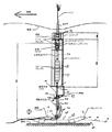
本発明に従った装置の全体図が図1に示されている。装置の一定の詳細が、図2及び図3により明白に示されている。図1及び図2は、閉鎖上端部12(図2)及び開放底端部14を有する細長い中空管10が示されている。使用の際、管10は、風で生じる表面波を有する水塊、たとえば海洋内に直立向きに(後述するように)完全に水没する。
[Description of Preferred Embodiment of the Invention]
A general view of the device according to the invention is shown in FIG. Certain details of the device are clearly shown in FIGS. FIGS. 1 and 2 show an elongated
本発明の装置の作動原理は、波の峰及び谷の通過による圧力変化として表すことができる水エネルギレベルの変化が水面付近で最大であり、これらの圧力変化が水面からの深さに伴って指数関数的に減少するということである。このため、完全に水没している長い管の上部は比較的大きい圧力変化を受けるが、管の底部は通過表面波にほとんど影響されないで、ほぼ一定の圧力を受ける。そのような一定圧力は、管底部と平均水位との間の水の重量にほぼ等しい。管の上端部及び底端部間の圧力変化により、(上記の同時係属中の特許出願第09/379,421号に開示されているように、開放端部を有する管で)波の峰が上端部を越える時、水が管の内部を流れ落ち、また、波の谷が管の上部にある時、水が管の内部を上向きに流れる。この加圧された水の流れにより、波動エネルギから機械力を取り出す可能性が生じる。閉鎖上端部を有する本明細書に示された管10では、表面波が誘発した圧力変化により、管10が垂直方向に振動する。この垂直振動がいかにして有用なエネルギに変換されるかを次に説明する。
The working principle of the device of the present invention is that the change in water energy level, which can be expressed as the pressure change due to the passage of wave peaks and troughs, is maximum near the water surface, and these pressure changes are accompanied by the depth from the water surface. It means that it decreases exponentially. For this reason, the upper part of a long tube that is completely submerged is subjected to a relatively large pressure change, but the bottom of the tube is almost unaffected by the passing surface wave and receives a substantially constant pressure. Such constant pressure is approximately equal to the weight of water between the tube bottom and the average water level. Due to the pressure change between the top and bottom ends of the tube, the peak of the wave (with a tube having an open end, as disclosed in the above-mentioned co-pending application 09 / 379,421). When the upper end is crossed, water flows down inside the tube, and when the wave valley is at the top of the tube, water flows upward inside the tube. This pressurized flow of water creates the possibility of extracting mechanical power from wave energy. In the
前述したように、管10は、ほぼ直立して、好ましくは完全に水没した向きに配置されている。(上記の同時係属中の特許出願第09/763247号に示されている構造と同様に)本明細書に示されている好適な実施形態では、管10が固定支持体に対して移動可能である。そのような支持体は、海底に取り付けられた剛直な構造体にすることができるが、後述するように、アンカーベース20の重量にアンカーチェーン21の重量を加えたものによって海底に係留されたアンカーベース20に固定されたフロート16であることが好ましい。
As previously mentioned, the
最も好都合には、管10(図2)がフロート16を包囲しており、管が垂直方向に細長いので、フロート16も同様に細長い。
Most conveniently, because the tube 10 (FIG. 2) surrounds the
フロート16は好ましくは、大きい浮力を示し、海底に固定的に取り付けられた固定構造体に対応するが、水平方向の水の動きに応じてフロートに多少の水平変位が生じる可能性がある点で異なる。フロートのそのような水平変位は通常低速で発生し、実質的にフロート16の機能は、管10用の固定位置にある支持体を提供することである。水塊の平均水位に対する管10及びフロートの位置の選択は、上記特許出願に記載されている。
The
アンカーベース20へのフロート16の好適な固定は、既知の形式の自在継手26によってアンカーベースに固定された鋼製の(船舶用塗料を塗布した)管状支柱24によるものである。このため、支柱24がアンカーベース20にしっかり取り付けられていながら、支柱は垂直向きから90度まで任意のコンパス方位に回動することができる。後述するように、そのように傾動できることは、システム及びそれからのパワー出力部の両方の耐久性を高める。図3に最もわかりやすく示されているアンカーベース20は、鋼ビームから作製されて、ベースの両側で末端が1対の鋼製浮きになっている。図1に示された水没位置では、浮きに水が充填されて、ベース20の重量を増加させている。浮きに空気を吹き込んで空気が満ちている時、浮きの浮力は、フロート16の浮力と合わせて、図1に示されている装置全体を浮動させるのに十分になる。そして、装置を水平浮動向きで水上船で牽引して搬送し、選択海洋場所に配備することができる。そのような場所で、浮きに水を徐々に注入して、ベース20を海底にゆっくり沈めることができ、装置は自動的に所望の垂直向きになる。
The preferred fixation of the
システムのさまざまな構成部品、たとえば、パワー変換器、センサなどはアンカーベース20上に好都合に取り付けられ、したがって、波の作用をまったく受けないが、保守点検または交換などのために、たとえばダイバーによるか、または海面からのワイヤスリングによってアクセスすることができる。
Various components of the system, such as power converters, sensors, etc. are conveniently mounted on the
アンカーベース20はそれのアンカーチェーン21と合わせて、通常の使用中に、すなわち、システムが安全に作動するように設計されている最大振幅までの表面波では(in connection with)、システムを所定位置にしっかり重力係留するのに十分な質量を有する。そのような最大振幅を超えて、一般的にシステムの可動部分に損傷を引き起こす可能性があるような巨大な力の波の場合、アンカーベースの質量は、別の方法で過大な垂直力を吸収するために海底から完全に浮き上がらせることができる程度に小さい。したがって、過大な高波状態では、アンカーベースは、海底から浮き上げられて再び海底に沈下する動作を繰り返し、システムが破損しない。また、ベースの移動中もフロート16に対する管10のストローク運動は継続することができ、それにより、他の点では(中程度の)危険な海面の嵐状態においても、発電が継続する。
The
上述したように、フロート16は、管状支柱24によってアンカーベース20にしっかり固定されている。管10は支柱24にも取り付けられているが、フロート16の上下に配置されて支柱24を取り囲む支承部34によって支柱に沿って摺動可能である。図2では、下側支承部34が、管10の内側にしっかり固定されたリング38に半径方向スポーク35によって連結された状態に示されている。図2では、管10の上端部に位置する固定リング38及び支承部34が破断して示され、1つのスポーク36だけが図示されている。作動中、管10はフロート16に対して支柱24に沿って往復動する。
As described above, the
固定フロートに対する管の移動が、波動エネルギ(管を駆動する力)を有用なエネルギに変換するメカニズムである。本明細書では、管10が、支柱24にしっかり取り付けられた油圧シリンダ46のピストン44に(図3に示すようにリング38を介して)固定的に接続されている。(往復動する管の運動エネルギを有用なエネルギに変換するための他の既知の機構、たとえば、発電機を使用することができる。)
The movement of the tube relative to the fixed float is a mechanism that converts wave energy (force that drives the tube) into useful energy. Here, the
本発明の1つの特徴は、管10がストローク減少リンク機構によって油圧シリンダピストン44に接続されていることである。これは、シリンダピストン44のより短い移動範囲を必要とするだけでありながら、管の移動が比較的広い範囲で変化することができる典型的な海洋状態によりうまく対応する。これの1つの利点は、より短く、従って一般的により低価格の油圧シリンダを使用することができることである。
One feature of the present invention is that the
本明細書では、ストローク減少リンク機構はレバー50(図3)を有し、その一端部52aが、管10の底端部14に位置するリング38に回動式に留め付けられた1対のロッド54(図1)に回動式に留め付けられている。レバー50の別の端部52bは、支柱24にポスト58でしっかり固定されたアクスル56(図1)の端部に回動式に留め付けられている。油圧ピストン44は、レバーの2端部52a及び52b間の長さの中程でレバー50に回動式に留め付けられており、したがって、ストロークの減少率は約1:2である。約1:2であるそのようなストローク減少率に対応して、レバー50によって伝達される力の大きさが約2:1になる。これの利点については後述する。
As used herein, the stroke reduction linkage has a lever 50 (FIG. 3), one end 52a of which is pivotally fastened to a ring 38 located at the
上述したように、支柱24は、自在継手によってアンカーベース20に取り付けられており、通過表面波によって発生する水の円運動に応じて支柱が回動または傾動することができる。支柱24(及びそれに取り付けられた機構)の前後方向の傾動内に存在する運動エネルギを捕捉するために、エネルギトランスジューサ、たとえば、垂直に配置された油圧シリンダ46と同様な油圧シリンダ46a(図4)が、シリンダの傾動に応じて往復動するように配置される。支柱の傾動はいずれの方向にも発生することができるので、シリンダ46aはその運動に対応するように取り付けられる。したがって、シリンダ46aはブラケット46b上にほぼ水平向きに取り付けられるが、ブラケット46bは、アンカーベース20に固定された垂直アクスル46eを中心にして水平方向に回転するように取り付けられたブラケット46dに取り付けられた水平アクスル46cを中心にして垂直方向に回転するように取り付けられる。
As described above, the
油圧シリンダ46aのピストン44bの端部44aを支柱24の回動点付近に、すなわち、自在継手26の少しだけ上方に取り付けることによって、ピストン44bの比較的少ない軸方向移動だけで、支柱の比較的大きい傾斜に対応することができる。
By attaching the end 44a of the piston 44b of the hydraulic cylinder 46a in the vicinity of the pivot point of the
支柱24の周囲に円周方向に配置された幾つかのトランスジューサを使用することができる。
Several transducers arranged circumferentially around the
過大な振幅の波に応じてシステムが吸収する過大な運動エネルギを消散させるために、緩衝すなわちストロークバッファ機構も設けられる。エネルギ吸収バッファ機構は既知であり、さまざまなそのような機構、たとえば、コイルばねを使用することができる。本明細書では、図2に示されているように、ストロークバッファ機構は、支柱24の上部分にしっかり固定された剛直なストライカバー60、たとえば、金属バーを有する。管10には、ストライカバー60の上方及び下方にそれぞれ配置された2つの緩衝アセンブリ62a及び62bが、固定ストライカバー60に対して管10と共に移動するように取り付けられている。2つのアセンブリ62a及び62bは、管10の内側にしっかり固定された剛直な筐体を形成する多数の相互連結ストラット部材を有する支持フレームアセンブリ64内にしっかり取り付けられている。アセンブリ62a及び62bの緩衝すなわちストロークバッファ部材は、既知の応力−歪み特性を有して衝撃エネルギに対して既知の弾性抵抗を与える弾性材料からなる2対の矩形ブロック68である。各対のブロックは、ストライカフレーム72及び向き合わせて配置された支持フレーム74間に取り付けられる。
A buffer or stroke buffer mechanism is also provided to dissipate the excessive kinetic energy that the system absorbs in response to excessive amplitude waves. Energy absorbing buffer mechanisms are known and various such mechanisms can be used, for example, coil springs. Herein, as shown in FIG. 2, the stroke buffer mechanism has a
作用を説明すると、上述したように、管10は、通過波に応じて、固定位置にある支柱24に対して上下に移動する。予想される振幅の最も一般的な波では、管10の移動は、緩衝アセンブリ62a及び62bを固定ストライカバー60に接触させるのに不十分であり、移動中の管10の運動エネルギのすべてが、有用なエネルギを発生するための油圧シリンダ46の往復運動に利用可能である。システムの安全作動範囲を超える増大振幅の通過波の場合、緩衝アセンブリ62a及び62bがストライカバー60に接触する位置へ駆動され、それにより、フロートのさらなる移動の制動及び停止が行われる。制動プロセスで、緩衝アセンブリ62a及び62bの弾性ブロック66が弾性的に降伏して、管10の運動エネルギを吸収し、それにより、支柱24に対する管の上昇または下降運動のいずれかを徐々に停止させる。
The operation will be described. As described above, the
上述したように、他の緩衝手段を使用することができる。本明細書で使用するシステムの利点は、広範囲の寸法かつ既知の応力−歪み特性で市販され、同様なエネルギ吸収機能用に個別に開発されたバッファ部材、たとえば、弾性ブロック66の使用に基づくことである。図2のフレーム72及び74として示すようなフレーム対の間に適当に組み合わされた弾性ブロック66は市販されている。
As mentioned above, other buffering means can be used. The advantages of the system used herein are based on the use of buffer members, such as
アンカーベース20は嵐の状態で移動すると予想されるが、それは一般的に所定位置に留まっていなければならない。この目的のため、海底にしっかり取り付けられているが、比較的長いチェーンによってベースに接続されている従来型アンカー60によってベース20が係留されていることが好ましい。長いチェーンは、システムがそれの係留場所から逃げることができないようにしながら、ベースの上記浮き上がり移動の自由を与える。ベース20の重量を増すために、比較的重いチェーンが使用される。
Although the
管10の上端部12及びフロート16の両方の内部に浮力タンクが配置されている。図2において、タンク80が管10の上部に(説明のために半分を切り落として)示され、また、直列型に並んだ個別タンク82が、管10の内側で支柱24を取り囲むように示されている。浮力タンク80及び82の目的は、海面の嵐が極めて激しい時、浮力タンクに水を注入して、管及びフロートを水没させることである。管及びフロートを支持している支柱24は自在継手によってスキッドベース20に固定されているので、支柱を傾斜させてシステムの上端部を表面波の高エネルギ帯より十分に下方の安全な深さまで移動させることによって、そのような「水没」を行うことができる。
Buoyancy tanks are disposed within both the
管10の上端部12の浮力タンク82のさらなる目的は、海洋生物の成長(marine growth)によるシステムの質量の変化に応じて、システムの浮力を調節することである。たとえば、海洋生物の成長が管またはフロートの重量を増加させ、それによって浮力の損失及び支柱の傾動を生じる場合、タンクからバラスト水を抜くことができる。
A further purpose of the buoyancy tank 82 at the
上述し、また上記引用の特許出願により十分に記載されているように、通過表面波は、管10の上端部及び底端部間に圧力変化を誘発する。そのような圧力変化は、管の閉鎖端部の両端で管内の水と周囲の水との間に現れ、そのような圧力変化に応じて、管10が上下に駆動される。過大な高波の場合、圧力差は、システムを破損させるほど非常に大きい力で管10を駆動する可能性がある。本発明に従ったさらなる安全特徴は、管10の上端部12に圧力逃がし手段を使用することである。最も簡単には、圧力逃がし手段は、管10の上端部12の上壁12a内にばね式フラップ84及び86を有することができる(図5)。フラップ84を比較的高い内部圧力に逆らって閉鎖位置にバイアスするために、また、フラップ86を比較的高い外部圧力に逆らって閉鎖位置にバイアスするためにコイルばね88が設けられている。管10内の水と周囲の水との間の正または負のいずれかの圧力差が、管10の閉鎖上端部の両端で所定レベルを超えると、ばねバイアスを掛けられているそれぞれのばね式フラップが押し開かれて圧力差を直ちに減少させ、したがって、そうでなければ管10に加わる過大な加速力を直ちに減少させる。圧力逃がし手段、たとえば、ばねポペット弁などが既知である。
As described above and more fully described in the above-cited patent application, passing surface waves induce pressure changes between the top and bottom ends of the
次に、システムの作用を要約する。 Next, the operation of the system is summarized.
通常の作動中、すなわち、予想される水位及び波振幅の場合、システムは海底にほぼ固定の垂直向きに載って、管20の閉鎖上端部12が、その時に最も一般的な波からエネルギを収集するのに最適な平均水位下の所定深さにある。表面波が管10を越えて通過する時、管がフロート16に対して上下に移動し、それによって油圧シリンダ46を往復動させて、その内部の作動油を加圧する。加圧された作動油は、(シリンダ内のピストンヘッドの上方及び下方に位置するシリンダの両端部から)圧力ホース72によって既知のトランスジューサ76、たとえば、発電機を駆動する油圧モータに送られる。(たとえば、水及び風から引き出される運動エネルギを変換する技術は既知であり、さまざまなそのようなエネルギ変換システムを使用することができることに留意されたい。)油圧シリンダに伝達される力の振幅を増大させるためにレバー50機構を使用するさらなる利点は、より大きい油圧を発生できることである。たとえば、1000〜2500psiの範囲内のそのような高圧は、油圧モータ、及び油圧モータによって駆動される発電機の作動効率を高めるのに有効である(と一般的に知られている)。
During normal operation, i.e. for the expected water level and wave amplitude, the system rests in a generally fixed vertical orientation on the seabed and the closed
海洋環境内に永久的に設置しようとするシステムすべてが直面する重大な問題は、海の嵐に備えた保護及び耐久性である。本明細書では、波の振幅が大きくなるほど、波によって生じる管の上端部及び底端部間の水圧変化が(上述した表面波効果に従って)増加し、それにより、フロート16に対する管10のストローク長さが大きくなりやすい。最初に、管10を増大力で駆動すると、管の過大なエネルギが上述のストロークバッファシステムによって吸収される。これにより、エネルギがバッファシステム内で失われるが、システムの破損が回避され、最も重要なことに、エネルギが依然としてシステムによって供給されている。
A serious problem faced by all systems that attempt to be permanently installed in the marine environment is protection and durability against sea storms. As used herein, the greater the amplitude of the wave, the greater the change in water pressure caused by the wave between the top and bottom ends of the tube (according to the surface wave effect described above) and thereby the stroke length of the
波の振幅がさらに増加し、管10にさらに大きい力が加わると、上部バッファシステムを設けた管上端部12の激しい衝撃がアンカーベース20の重量に打ち勝って、それにより、アンカーベースを海底から浮き上がらせる(しかし、それはアンカー60から解放されない)。アンカーベース20の浮き上がりも、エネルギ吸収手段であり、それにより、システムがさらに保護される。各波に対して、ベース20が最初に浮き上がり、次に押し下げられて海底80に当たるが、何らかの破損が生じるほどに激しくないことに留意されたい。やはり、アンカーベースのそのような移動中にも、エネルギがシステムによって発生している。
As the wave amplitude further increases and a greater force is applied to the
さらに大きい波の場合、圧力逃がし弁が開放して、管10を駆動する圧力差を減少させる。最終的に、波エネルギが非常に大きくなって、エネルギ消散手段ではもはやシステムを保護できなくなると、バラスト水が浮力タンクに取り込まれて、表面波の下方の十分な深さまで管を水没させる。
For larger waves, the pressure relief valve opens to reduce the pressure differential driving the
作動中、システム制御装置は、海面から十分に下方にあるアンカーベース20上に安全に配置されている。スキッドベースの移動が上述したように発生する可能性はあるが、アンカーベースの上方及び下方の水がそれの動きを緩衝する傾向があり、過大な加速及び衝撃を部分的に減少させる。
In operation, the system controller is safely located on the
上述したように、性能を最適化すると共にシステムを破損から保護するために、浮力タンクが使用される。反復動作には、パワー及び空気源の両方が必要である。 As mentioned above, buoyancy tanks are used to optimize performance and protect the system from damage. Repetitive motion requires both power and air source.
システムは、(作動油を長距離にわたって往復動させることを避けるために)好ましくは現場で発電し、一部の電力は、バラストタンクを作動させるためにアンカーベース上のバッテリに蓄電される。 The system preferably generates power on-site (to avoid reciprocating hydraulic oil over long distances) and some power is stored in a battery on the anchor base to activate the ballast tank.
図1に示されている(図2では省略されている)ように、管10の上端部にマスト90が取り付けられて、海面及びその波の上方に延出しており、それにより、(一般的にWEC海域内の)WECの位置を目視及び電子的に決定することができる。また、WECの状態を詳細に示す無線信号を放送することができ、また、システムの作動、たとえば、バラストタンク80及び82の注水及び吹き出しのために、無線信号を電線で水没中の制御システムに対して送受信することができる。マストは好ましくは空気管を有して、マストを通してバラストタンク用の保管タンク内へ空気を注入できるようにする。
As shown in FIG. 1 (omitted in FIG. 2), a mast 90 is attached to the upper end of the
Claims (2)
該装置を前記水塊の底面に係留するためのベース部材と、
を備えており、前記第2部材は、該ベース部材に固定的に取り付けられており、前記ベース部材は、前記所定振幅までの表面波の存在中、前記ベース部材を前記底面に接触させておくだけの十分な重量を有しながら、前記所定振幅を超える所定の第2振幅を有する表面波の通過中、前記ベース部材を前記底面から浮き上がらせることができる装置。A device for capturing energy from a surface wave having an amplitude within a certain range up to a predetermined maximum amplitude on the water mass, wherein the device captures energy from the second member in response to a passing wave. A first member capable of reciprocating along a path having a length that is a function of the instantaneous amplitude of the passing wave;
A base member for mooring the device to the bottom surface of the water mass;
The second member is fixedly attached to the base member, and the base member keeps the base member in contact with the bottom surface in the presence of surface waves up to the predetermined amplitude. An apparatus capable of floating the base member from the bottom surface while passing a surface wave having a predetermined second amplitude exceeding the predetermined amplitude while having a sufficient weight.
Applications Claiming Priority (2)
| Application Number | Priority Date | Filing Date | Title |
|---|---|---|---|
| US10/080,181 US6768217B2 (en) | 2002-02-20 | 2002-02-20 | Wave energy converter system of improved efficiency and survivability |
| PCT/US2003/004574 WO2003071128A2 (en) | 2002-02-20 | 2003-02-14 | Wave energy converter system of improved efficiency and survivability |
Publications (3)
| Publication Number | Publication Date |
|---|---|
| JP2005530075A JP2005530075A (en) | 2005-10-06 |
| JP2005530075A5 JP2005530075A5 (en) | 2006-02-23 |
| JP4436684B2 true JP4436684B2 (en) | 2010-03-24 |
Family
ID=27733163
Family Applications (1)
| Application Number | Title | Priority Date | Filing Date |
|---|---|---|---|
| JP2003570002A Expired - Fee Related JP4436684B2 (en) | 2002-02-20 | 2003-02-14 | Wave energy conversion system with improved efficiency and durability |
Country Status (10)
| Country | Link |
|---|---|
| US (1) | US6768217B2 (en) |
| EP (1) | EP1516118B1 (en) |
| JP (1) | JP4436684B2 (en) |
| AU (1) | AU2003213077B2 (en) |
| CA (1) | CA2476627C (en) |
| ES (1) | ES2383678T3 (en) |
| NO (1) | NO20050496L (en) |
| NZ (1) | NZ534725A (en) |
| PT (1) | PT1516118E (en) |
| WO (1) | WO2003071128A2 (en) |
Families Citing this family (47)
| Publication number | Priority date | Publication date | Assignee | Title |
|---|---|---|---|---|
| US20040201222A1 (en) * | 2002-12-10 | 2004-10-14 | Leonid Eylman | Power station utilizing potential energy of sea water pressure |
| SE0300869L (en) * | 2003-03-27 | 2004-03-23 | Swedish Seabased Energy Ab | Wave power units |
| US20050127678A1 (en) * | 2003-12-11 | 2005-06-16 | Kenneth Rea | System for generating power through the capture of gas bubbles and method therefor |
| US7042112B2 (en) * | 2004-02-03 | 2006-05-09 | Seawood Designs Inc. | Wave energy conversion system |
| GB0505906D0 (en) * | 2005-03-23 | 2005-04-27 | Aquamarine Power Ltd | Apparatus and control system for generating power from wave energy |
| ES2547954T3 (en) * | 2005-08-12 | 2015-10-09 | Biopower Systems Pty. Ltd. | A wave energy capture device |
| US7322189B2 (en) * | 2005-12-19 | 2008-01-29 | General Electric Company | Wide bandwidth farms for capturing wave energy |
| US7762776B2 (en) * | 2006-03-14 | 2010-07-27 | Siegel Aerodynamics, Inc. | Vortex shedding cyclical propeller |
| US7686583B2 (en) * | 2006-07-10 | 2010-03-30 | Siegel Aerodynamics, Inc. | Cyclical wave energy converter |
| AU2007272290B2 (en) * | 2006-07-11 | 2011-06-16 | Protean Energy Australia Pty Ltd | Wave energy converter |
| US20080217919A1 (en) * | 2006-11-22 | 2008-09-11 | Shamil Sami Ayntrazi | Renewable energy wave air pump |
| DK176417B1 (en) * | 2006-11-28 | 2008-01-14 | Bjoern Rothausen | Method of optimizing drift of power machinery mounted on ship or float by using gravitation force, involves loosely placing valve on bottom of sea, placed partly movable sidewards on bottom of sea |
| EP2162617B1 (en) * | 2006-11-28 | 2012-08-22 | 40South Energy Limited | A completely submerged wave energy converter |
| NO326269B1 (en) * | 2007-01-30 | 2008-10-27 | Ernst Johnny Svelund | Facility for utilization of ocean energy. |
| CA2693782A1 (en) * | 2007-07-11 | 2009-01-15 | Ryan Steelberg | A deep water power generation system and apparatus |
| GB2457423A (en) * | 2007-11-02 | 2009-08-19 | Univ Manchester | Wave energy float shaped to control water washing over top surface |
| BRPI0819527A2 (en) | 2007-12-17 | 2015-05-26 | Carnegie Wave Energy Ltd | "floating actuator and system for converting waves to energy" |
| CN102027229A (en) * | 2008-04-11 | 2011-04-20 | 澳大利亚持续能源有限公司 | System and method for deploying and retrieving a wave energy converter |
| US20110155039A1 (en) * | 2008-04-11 | 2011-06-30 | Sean Derek Moore | System and method for deploying and retrieving a wave energy converter |
| US8901766B2 (en) * | 2008-06-12 | 2014-12-02 | Alexander K. Werjefelt | Wave action electric generating system including a boom on a floating platform |
| GB2461792A (en) * | 2008-07-14 | 2010-01-20 | Marine Power Systems Ltd | Wave generator with optional floating configuration |
| US8464527B2 (en) * | 2008-11-21 | 2013-06-18 | Ocean Power Technologies, Inc. | Float for wave energy converter (WEC) |
| US7948108B2 (en) * | 2009-02-06 | 2011-05-24 | Ignacio Peralta | Systems and methods for converting marine currents into electrical energy |
| US20110248503A1 (en) * | 2009-07-15 | 2011-10-13 | Ventz George A | Wave driven pump and power generation system |
| BR112012003813B1 (en) * | 2009-08-19 | 2021-02-23 | Werjefelt Alexander | electrical generation system by wave action |
| US20110057448A1 (en) * | 2009-09-08 | 2011-03-10 | Joseph Page | Wave energy converters |
| EP2320068A1 (en) * | 2009-11-09 | 2011-05-11 | New Ecology V.O.F. | Device for converting wave energy into electrical energy |
| NO331603B1 (en) * | 2009-11-24 | 2012-02-06 | Asbjorn Skotte | Procedure for operation of bulb converter and bulb power plant |
| BR112012014103B1 (en) * | 2009-12-04 | 2017-02-14 | Henry Terry | ocean powered power plant |
| CN101858299B (en) * | 2010-05-14 | 2013-08-21 | 河海大学 | Wave power generation capsule |
| US20120032444A1 (en) * | 2010-08-06 | 2012-02-09 | John Alan Burton | Wave Catcher |
| US9175664B2 (en) * | 2010-08-16 | 2015-11-03 | Ceto Ip Pty Ltd. | Wave energy conversion |
| CN102606376B (en) * | 2012-04-01 | 2016-06-01 | 海南省蓝波新能源科技有限公司 | A kind of based on hydraulicdriven wave energy voltage stabilizing constant frequency generation device |
| US8937395B2 (en) * | 2012-08-08 | 2015-01-20 | Atargis Energy Corporation | Ocean floor mounting of wave energy converters |
| US8629572B1 (en) | 2012-10-29 | 2014-01-14 | Reed E. Phillips | Linear faraday induction generator for the generation of electrical power from ocean wave kinetic energy and arrangements thereof |
| US9624900B2 (en) | 2012-10-29 | 2017-04-18 | Energystics, Ltd. | Linear faraday induction generator for the generation of electrical power from ocean wave kinetic energy and arrangements thereof |
| US10011910B2 (en) | 2012-10-29 | 2018-07-03 | Energystics, Ltd. | Linear faraday induction generator for the generation of electrical power from ocean wave kinetic energy and arrangements thereof |
| CL2013000260A1 (en) * | 2013-01-25 | 2013-08-09 | Echeverria Ivan Dib | Mechanism for the capture of energy from waves, consisting of a platform that supports at least one means of flotation, composed of at least one motive pond, where one or more motive ponds are encased in a structural cage, where a central column passes through the center of said motive tank and is articulated by means of a pivot connected to a supporting structure, a vertical capture hydraulic cylinder, with a vertical plunger connected to the motive pond. |
| EP3097306A1 (en) * | 2014-01-08 | 2016-11-30 | AW-Energy Oy | Surface level follow-up arrangement for a wave energy recovery system |
| CN104314736B (en) * | 2014-10-21 | 2017-01-18 | 华南理工大学 | Totally-enclosed power generation device simultaneously utilizing wave energy and wind energy |
| CN205632946U (en) * | 2015-07-06 | 2016-10-12 | 周剑辉 | General offshore platform |
| US10767618B2 (en) * | 2016-04-24 | 2020-09-08 | The Regents Of The University Of California | Submerged wave energy converter for shallow and deep water operations |
| US11002243B2 (en) | 2017-04-24 | 2021-05-11 | The Regents Of The University Of California | Submerged wave energy converter for deep water operations |
| US10047717B1 (en) | 2018-02-05 | 2018-08-14 | Energystics, Ltd. | Linear faraday induction generator for the generation of electrical power from ocean wave kinetic energy and arrangements thereof |
| US10526056B1 (en) * | 2019-04-29 | 2020-01-07 | Physician Electronic Network, LLC | Generation of electric power using wave motion, wind energy and solar energy |
| US11946463B2 (en) * | 2021-11-08 | 2024-04-02 | BlueDesal Inc. | Wave driven variable leverage pump for water desalination |
| CN114109929B (en) * | 2021-11-23 | 2023-02-28 | 山东大学 | Integrated hydraulic conversion oil cylinder applied to wave power generation device and using method thereof |
Family Cites Families (20)
| Publication number | Priority date | Publication date | Assignee | Title |
|---|---|---|---|---|
| FR892537A (en) * | 1942-12-04 | 1944-04-11 | Device using the movements of the sea and more particularly of the swell for the production of energy | |
| US4076463A (en) * | 1976-10-26 | 1978-02-28 | Mordechai Welczer | Wave motor |
| NO771013L (en) * | 1977-03-22 | 1978-09-25 | Kjell Budal | BOELGEKRAFTVERK. |
| FR2423651A1 (en) * | 1978-04-20 | 1979-11-16 | Emh | Generator utilising sea and wind energy - has float in hollow tube pivoted at base to react to all movements |
| GB2033488B (en) * | 1978-07-19 | 1982-09-15 | Sea Energy Associates Ltd | Wave powered energy generator |
| US4455824A (en) * | 1981-06-01 | 1984-06-26 | Gustav Dabringhaus Revocable Trust | Wave motor |
| AU2335884A (en) * | 1982-11-29 | 1984-06-18 | P. Wood | Wave power converter |
| US4754157A (en) * | 1985-10-01 | 1988-06-28 | Windle Tom J | Float type wave energy extraction apparatus and method |
| US4742241A (en) * | 1986-04-01 | 1988-05-03 | Melvin Kenneth P | Wave energy engine |
| US4851704A (en) * | 1988-10-17 | 1989-07-25 | Rubi Ernest P | Wave action electricity generation system and method |
| DK166969B1 (en) * | 1990-10-03 | 1993-08-09 | Danish Wave Power | HUMAN POWER PLANT |
| US5324988A (en) * | 1993-07-23 | 1994-06-28 | Edwin Newman | System for undersea wave generation of electric power |
| SE508307C2 (en) * | 1996-04-29 | 1998-09-21 | Ips Interproject Service Ab | wave energy converters |
| US5842838A (en) * | 1996-11-04 | 1998-12-01 | Berg; John L. | Stable wave motor |
| US6229225B1 (en) * | 1997-05-08 | 2001-05-08 | Ocean Power Technologies, Inc. | Surface wave energy capture system |
| US6020653A (en) * | 1997-11-18 | 2000-02-01 | Aqua Magnetics, Inc. | Submerged reciprocating electric generator |
| NZ505410A (en) * | 1997-12-03 | 2002-02-01 | Dick William | A wave energy converter |
| US5955790A (en) * | 1998-03-13 | 1999-09-21 | North; Vaughn W. | Apparatus for converting tide/wave motion to electricity |
| IL124902A0 (en) * | 1998-06-14 | 1999-01-26 | Feldman Yosef | Hydrostatic wave energy conversion system |
| GB9916779D0 (en) * | 1999-07-16 | 1999-09-15 | Kelly H P G | Sea wave to electrical energy conversion plant |
-
2002
- 2002-02-20 US US10/080,181 patent/US6768217B2/en not_active Expired - Lifetime
-
2003
- 2003-02-14 WO PCT/US2003/004574 patent/WO2003071128A2/en active Application Filing
- 2003-02-14 NZ NZ534725A patent/NZ534725A/en not_active IP Right Cessation
- 2003-02-14 JP JP2003570002A patent/JP4436684B2/en not_active Expired - Fee Related
- 2003-02-14 PT PT03709120T patent/PT1516118E/en unknown
- 2003-02-14 EP EP03709120A patent/EP1516118B1/en not_active Expired - Lifetime
- 2003-02-14 ES ES03709120T patent/ES2383678T3/en not_active Expired - Lifetime
- 2003-02-14 AU AU2003213077A patent/AU2003213077B2/en not_active Ceased
- 2003-02-14 CA CA2476627A patent/CA2476627C/en not_active Expired - Lifetime
-
2005
- 2005-01-28 NO NO20050496A patent/NO20050496L/en not_active Application Discontinuation
Also Published As
| Publication number | Publication date |
|---|---|
| CA2476627A1 (en) | 2003-08-28 |
| EP1516118A2 (en) | 2005-03-23 |
| JP2005530075A (en) | 2005-10-06 |
| NO20050496L (en) | 2005-01-31 |
| NZ534725A (en) | 2007-01-26 |
| AU2003213077A1 (en) | 2003-09-09 |
| EP1516118A4 (en) | 2007-01-10 |
| US20030155774A1 (en) | 2003-08-21 |
| US6768217B2 (en) | 2004-07-27 |
| EP1516118B1 (en) | 2012-04-18 |
| WO2003071128A2 (en) | 2003-08-28 |
| ES2383678T3 (en) | 2012-06-25 |
| WO2003071128A3 (en) | 2003-12-31 |
| AU2003213077B2 (en) | 2008-10-23 |
| PT1516118E (en) | 2012-07-16 |
| CA2476627C (en) | 2011-10-04 |
Similar Documents
| Publication | Publication Date | Title |
|---|---|---|
| JP4436684B2 (en) | Wave energy conversion system with improved efficiency and durability | |
| CA2729927C (en) | Wave actuated pump and means of connecting same to the seabed | |
| AU2009272416B2 (en) | Wave powered generator | |
| CA2683644C (en) | Wave power generator systems | |
| KR102373405B1 (en) | A device for converting wave energy into electrical energy and a process for placing such a device at a deployment location | |
| US11279452B2 (en) | Motion absorbing system and method for a structure | |
| US8604631B2 (en) | Ocean wave energy converter with multiple capture modes | |
| US8581432B2 (en) | Ocean wave energy converter capturing heave, surge and pitch motion | |
| US9657710B2 (en) | Dynamic tuning for wave energy conversion | |
| JP2009542964A (en) | Wave energy converter | |
| JP2010521613A (en) | Wave power plant | |
| CA2666259A1 (en) | Wave energy converter | |
| WO2009109701A1 (en) | Wave power plant | |
| CN115743444A (en) | Flexible wave-resistant stable structure based on floating type offshore monitoring platform | |
| WO2008048050A1 (en) | Wave energy converter | |
| KR20090124351A (en) | Sinkable vertical membrane breakwater | |
| EP2713042A2 (en) | Dynamic tuning for wave energy conversion | |
| CN111335250A (en) | Pile-guiding type floating breakwater and wave energy conversion integrated system and working method thereof | |
| EP4086159A2 (en) | Motion absorbing system and method for a structure | |
| KR20240024896A (en) | wave energy capture device |
Legal Events
| Date | Code | Title | Description |
|---|---|---|---|
| A521 | Request for written amendment filed |
Free format text: JAPANESE INTERMEDIATE CODE: A523 Effective date: 20051228 |
|
| A621 | Written request for application examination |
Free format text: JAPANESE INTERMEDIATE CODE: A621 Effective date: 20051228 |
|
| A131 | Notification of reasons for refusal |
Free format text: JAPANESE INTERMEDIATE CODE: A131 Effective date: 20080602 |
|
| A601 | Written request for extension of time |
Free format text: JAPANESE INTERMEDIATE CODE: A601 Effective date: 20080902 |
|
| A602 | Written permission of extension of time |
Free format text: JAPANESE INTERMEDIATE CODE: A602 Effective date: 20080909 |
|
| A521 | Request for written amendment filed |
Free format text: JAPANESE INTERMEDIATE CODE: A523 Effective date: 20081127 |
|
| A131 | Notification of reasons for refusal |
Free format text: JAPANESE INTERMEDIATE CODE: A131 Effective date: 20090803 |
|
| A521 | Request for written amendment filed |
Free format text: JAPANESE INTERMEDIATE CODE: A523 Effective date: 20091008 |
|
| TRDD | Decision of grant or rejection written | ||
| A01 | Written decision to grant a patent or to grant a registration (utility model) |
Free format text: JAPANESE INTERMEDIATE CODE: A01 Effective date: 20091202 |
|
| A01 | Written decision to grant a patent or to grant a registration (utility model) |
Free format text: JAPANESE INTERMEDIATE CODE: A01 |
|
| A61 | First payment of annual fees (during grant procedure) |
Free format text: JAPANESE INTERMEDIATE CODE: A61 Effective date: 20091228 |
|
| R150 | Certificate of patent or registration of utility model |
Ref document number: 4436684 Country of ref document: JP Free format text: JAPANESE INTERMEDIATE CODE: R150 Free format text: JAPANESE INTERMEDIATE CODE: R150 |
|
| FPAY | Renewal fee payment (event date is renewal date of database) |
Free format text: PAYMENT UNTIL: 20130108 Year of fee payment: 3 |
|
| FPAY | Renewal fee payment (event date is renewal date of database) |
Free format text: PAYMENT UNTIL: 20140108 Year of fee payment: 4 |
|
| R250 | Receipt of annual fees |
Free format text: JAPANESE INTERMEDIATE CODE: R250 |
|
| R250 | Receipt of annual fees |
Free format text: JAPANESE INTERMEDIATE CODE: R250 |
|
| R250 | Receipt of annual fees |
Free format text: JAPANESE INTERMEDIATE CODE: R250 |
|
| R250 | Receipt of annual fees |
Free format text: JAPANESE INTERMEDIATE CODE: R250 |
|
| R250 | Receipt of annual fees |
Free format text: JAPANESE INTERMEDIATE CODE: R250 |
|
| R250 | Receipt of annual fees |
Free format text: JAPANESE INTERMEDIATE CODE: R250 |
|
| R250 | Receipt of annual fees |
Free format text: JAPANESE INTERMEDIATE CODE: R250 |
|
| LAPS | Cancellation because of no payment of annual fees |