JP4435522B2 - Door fixing device - Google Patents
Door fixing device Download PDFInfo
- Publication number
- JP4435522B2 JP4435522B2 JP2003316930A JP2003316930A JP4435522B2 JP 4435522 B2 JP4435522 B2 JP 4435522B2 JP 2003316930 A JP2003316930 A JP 2003316930A JP 2003316930 A JP2003316930 A JP 2003316930A JP 4435522 B2 JP4435522 B2 JP 4435522B2
- Authority
- JP
- Japan
- Prior art keywords
- lever
- open lever
- opener
- open
- piece
- Prior art date
- Legal status (The legal status is an assumption and is not a legal conclusion. Google has not performed a legal analysis and makes no representation as to the accuracy of the status listed.)
- Expired - Fee Related
Links
Images


Landscapes
- Lock And Its Accessories (AREA)
Description
自動車のバックドア、トランクリッド等を固定するのに好適なドア固定装置に関する。 The present invention relates to a door fixing device suitable for fixing a back door, a trunk lid and the like of an automobile.
自動車のバックドア、トランクリッド等を固定する装置として、ドア及びドア支持体の一方に固定されたストライカと、他方に装着されたラッチ、ディテントレバー及びオープンレバーを有する本体機構とから成るドアロック装置が知られている。
このようなドアロック装置では、ドアを閉じてストライカがオープン状態のラッチに衝突すると、その衝撃でラッチがストライカと係合したままクローズ状態へ回動し、ドアとドア支持体とが互いに引き寄せられる。そして、クローズ状態のラッチにディテントレバーが係合してラッチの逆転を規制し、ドアが閉じた状態で固定される。
A door lock device comprising a striker fixed to one of a door and a door support and a main body mechanism having a latch, a detent lever and an open lever mounted on the other as a device for fixing a back door, a trunk lid, etc. of an automobile It has been known.
In such a door lock device, when the door is closed and the striker collides with the latch in the open state, the latch rotates with the impact engaged with the striker, and the door and the door support are attracted to each other. . Then, the detent lever engages with the latch in the closed state to restrict the reverse rotation of the latch, and the door is fixed in the closed state.
一方、オープンレバーを回動操作すると、ディテントレバーがラッチから引き離され、この結果、ラッチが逆転してオープン状態となり、ラッチとストライカとの係合が解除されるため、ドアを開けることができる。
ドアが開いた後は、ディテントレバーはバネに付勢されて、ラッチと接近する方向へ復帰し、オープンレバーはリターンスプリングの付勢力によって、ディテントレバーに作用しない元の位置へ復帰する(例えば、特許文献1参照)。
ところが、上記従来のオープンレバーでは、回転中心が重心から離れた作用点に近い位置に設けられているので、ドアを閉じたときの衝撃或いは衝突時の衝撃でオープンレバーが大きく振れ、慣性力がオープンレバーの復帰を妨げる方向に働くため、リターンスプリングに大きな負荷が加わると共に、ディテントレバーの復帰が阻害され、この結果、ラッチの逆転が規制されず、ラッチとストライカとの係合が解除されてドアが開いてしまう虞がある。
On the other hand, when the open lever is turned, the detent lever is pulled away from the latch. As a result, the latch is reversely rotated to be in the open state, and the engagement between the latch and the striker is released, so that the door can be opened.
After the door is opened, the detent lever is biased by the spring and returns to the direction approaching the latch, and the open lever is returned to the original position where it does not act on the detent lever by the biasing force of the return spring (for example, Patent Document 1).
However, in the conventional open lever, the center of rotation is provided at a position close to the point of action away from the center of gravity, so the open lever swings greatly due to the impact when the door is closed or the impact at the time of collision, and the inertial force is reduced. Since it works in a direction that hinders the return of the open lever, a large load is applied to the return spring and the return of the detent lever is inhibited. As a result, the reverse rotation of the latch is not regulated and the engagement between the latch and the striker is released. There is a risk of the door opening.
本発明が解決しようとする課題は、オープンレバーをロック解除位置から元の位置へ復帰させるリターンスプリングの出力を軽減でき、オープンレバーに働く慣性によってラッチとストライカとの係合が解除されるのを防ぐことができるドア固定装置を提供することにある。 The problem to be solved by the present invention is that the output of the return spring that returns the open lever from the unlocked position to the original position can be reduced, and the engagement between the latch and the striker is released by the inertia acting on the open lever. It is in providing the door fixing device which can be prevented.
本発明のドア固定装置は、ドア及びドア支持体の一方に固定されたストライカと、他方に装着されたラッチ、ディテントレバー、オープンレバーとを備え、前記ラッチはクローズ位置へ回動して前記ストライカと係合し、前記ディテントレバーを解除位置へ回動することにより、前記ラッチは前記ストライカとの係合が解除されるオープン位置へ回動するものであって、上記課題を解決するために、
前記オープンレバーは、棒状部材で形成され、
前記オープンレバーの長手方向の中央部分が回転中心として回動自在に支持され、
前記オープンレバーの一端部に、前記オープンレバーの長手方向に沿ってロック位置と非ロック位置との間を摺動可能かつ前記オープンレバーと共に回動するオープナが設けられ、前記オープンレバーの他端部に操作ケーブルが連結され、
さらに、
前記ディテントレバーの一端に当接片が形成され、
前記オープンレバーの一端部に前記当接片を挟んで前後部に配置される前片及び後片が設けられ、前記前片及び後片に前記オープンレバーの長手方向に長い長孔が対向して設けられ、
前記オープナに、該オープナの摺動方向及び前記オープンレバーの回動方向に交差し、前記オープンレバーの前片及び後片に形成された前記長孔に摺動自在に係合する押圧軸が設けられ、
前記オープナが前記ディテントレバーから遠ざかる方向に前記オープンレバーを付勢するリターンスプリングが設けられ、
前記オープナがロック位置にある時に、前記操作ケーブルを操作して前記オープンレバーを回動させた場合、前記オープナの前記押圧軸は前記当接片に作用せず、
前記オープナが非ロック位置にある時に、前記操作ケーブルを操作して前記オープンレバーを回動させた場合、前記オープナの前記押圧軸が前記当接片にぶつかり、前記ディテントレバーを解除位置へ回動させる、ことを特徴とする。
Door securing device of the present invention comprises a striker that is fixed to one of the door and the door support, the other to the loaded latched, the detent lever, the open levers, the latch is pivoted to the closed position To engage the striker and rotate the detent lever to the release position, the latch rotates to the open position where the engagement with the striker is released. In addition,
The open lever is formed of a rod-shaped member,
A central portion in the longitudinal direction of the open lever is supported rotatably about a rotation center,
One end of the open lever is provided with an opener that is slidable between a lock position and a non-lock position along the longitudinal direction of the open lever and that rotates with the open lever, and the other end of the open lever The operation cable is connected to
further,
A contact piece is formed at one end of the detent lever,
A front piece and a rear piece arranged at the front and rear portions with the contact piece sandwiched between one end portion of the open lever are provided, and a long hole in the longitudinal direction of the open lever is opposed to the front piece and the rear piece. Provided,
The opener is provided with a pressing shaft that intersects the sliding direction of the opener and the rotation direction of the open lever and slidably engages with the long holes formed in the front piece and the rear piece of the open lever. And
A return spring that biases the open lever in a direction in which the opener moves away from the detent lever;
When the open lever is rotated by operating the operation cable when the opener is in the locked position, the pressing shaft of the opener does not act on the contact piece,
When the opener is in the unlocked position, when rotated the opening lever by operating the operation cable, the said pressing axis of the opener hit the contact piece, times the detent lever to the release position Ru is dynamic, and wherein the.
本発明によれば、オープンレバーがその中心部近傍を回転中心として回動自在に支持されているので、ドアを閉じた時の衝撃或いは衝突時の衝撃によって生ずるオープンレバーの振れが小さくて済み、オープンレバーを元の位置に復帰させるリターンスプリングに加わる負荷が軽減され、このため、リターンスプリングを小さくできて、ハンドルの操作力を軽減できると共に、オープンレバーによりディテントレバーの復帰が阻害されて、ラッチとストライカとの係合が解除されるのを防ぐことができる。 According to the present invention, since the open lever is supported so as to be rotatable around its center portion as a rotation center, the swing of the open lever caused by the impact when the door is closed or the impact at the time of the collision is small. The load applied to the return spring that returns the open lever to the original position is reduced, which makes it possible to reduce the return spring and reduce the operating force of the handle, and the open lever prevents the detent lever from returning and latches. And the striker can be prevented from being disengaged.
以下、自動車のバックドア固定装置である実施例について、図面に基づき詳細に説明する。
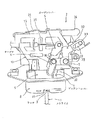
本発明のドア固定装置は、図1及び図2に示すように、ドア支持体である開口部下縁に固定されたストライカ1と、バックドアに装着されたラッチ3、ディテントレバー4、オープンレバー5及びロックレバー7を有する本体機構2とから成る。
ストライカ1は、金属棒を略コ字状に折り曲げて成り、上方に突出するよう設置されている。
Hereinafter, an embodiment which is an automobile back door fixing device will be described in detail with reference to the drawings.
As shown in FIGS. 1 and 2, the door fixing device of the present invention includes a
The
本体機構2は、バックドアの下面に露出して固定される箱状のカバー8と、カバー8内に収納・固定されたラッチベース9と、ラッチベース9の上面に取り付けられたアッパープレート10とを備える。
カバー8は金属製であり、その下面にはストライカ進入口11が形成されている。
ラッチベース9は、合成樹脂を素材とし、図7に示すように、その上面には複数の突起12が互いに間隔をおいて突出されている。また、図2に示すように、ラッチベース9の下面において、カバー8のストライカ進入口11と一致する位置には、ストライカ受入れ凹部13が形成されている。
アッパープレート10は、金属板を折り曲げて成り、図7及び図8に示すように、ラッチベース9の上面に固定された固定片14と、固定片の一端を上方へ屈曲した起立片15とを有する。
The
The
The
The
ラッチ3は、ラッチベース9の下面において、ストライカ受入れ凹部13を挟んだ一側に、ラッチベース9を上下に貫通する第1のシャフト16によって回動自在に取り付けられる。
また、ラッチ3には、ストライカ1と係合する切欠が形成される。ラッチ3がオープン状態にある時は、この切欠がストライカ進入口11の開口側に向かって開口している。
ところが、バックドアを閉じてストライカ進入口11へ進入したストライカ1がラッチ3に衝突し、その衝撃でラッチ3が回動すると、切欠がストライカ1を受け入れたまま回転してストライカ進入口11を横切り、ストライカ1がストライカ進入口11から脱出できなくなり、バックドアは閉じた状態で固定される。なお、ラッチ3は、第1のシャフト16の外周に装着された第1のバネ17により、オープン方向へ付勢されている。
The
Further, the
However, when the back door is closed and the
ディテントレバー4は、ラッチベース9の下面において、ストライカ受入れ凹部13を挟んだ他側に、図8に示すように、ラッチベース9を上下に貫通する第2のシャフト18によって回動自在に取り付けられる。
また、ディテントレバー4は第2のシャフト18の外周に装着された第2のバネ19により、ラッチ3の外周面に接近する方向へ付勢され、クローズ状態のラッチ3に係合して、ラッチ3がオープン状態へ回動するのを規制するようになっている。
As shown in FIG. 8, the
Further, the
クローズ状態のラッチ3と係合しているディテントレバー4を、第2のバネ19の付勢力に抗して解除方向へ回動させると、第1のバネ17に付勢されているラッチ3は一挙にオープン位置へ戻り、ラッチ3とストライカ1との係合を解除して、バックドアを開けることができる。
さらに、ディテントレバー4の一端は上方へ起立して、ラッチベース9の前方に露出する当接片20が形成されている。
なお、このようなストライカ1、ラッチ3及びディテントレバー4の関連構造は従来公知なので、作動順序は図示しない。
When the
Further, one end of the
Since the related structure of the
アッパープレート10の固定片14はラッチベース9の突起12上に載置され、第1のシャフト16及び第2のシャフト18によりラッチベース9の上面に固定される。図2に示すように、アッパープレート10の起立片15の後面にはモータケース21が装着される。
図1及び図6に示すように、起立片15の前面他側寄り(ディテントレバー4寄り)にはオープンレバー5が回動可能に取り付けられる。
オープンレバー5は、断面略コ字状の真っ直ぐな棒状に形成され、その上端部に操作ケーブル27の先端が連結される。また、オープンレバー5の下端部は、ディテントレバー4の当接片20の一側に臨んでおり、この部分にディテントレバー4に作用するオープナ6が設けられる。
The
As shown in FIGS. 1 and 6, the
The
図3及び図5に示すように、オープンレバー5の中心部近傍(長手方向中央部近傍)において、起立片15に接する側片を、回動中心となる第1の支軸22が貫通している。また、オープンレバー5は、第1の支軸22の外周に巻回したリターンスプリング23によって、オープナ6がディテントレバー4の当接片20から遠ざかる方向に付勢されている。
さらに、オープンレバー5の下端部には、当接片20を挟んでその前後部に配置される前片24及び後片25が設けられ、前片24及び後片25には軸方向に長い長孔26がそれぞれ対向するよう形成される(図6)。なお、長孔26の上端部は、ディテントレバー4の当接片20よりも上方に位置し、長孔26の下端部は、当接片20の上端よりも下方に達している。
そして、操作ケーブル27を操作してオープンレバー5の上端部を一側へ引っ張ると、オープンレバー5が回動して、その前片24及び後片25が当接片20の前後側を通過するようになっている。
As shown in FIGS. 3 and 5, in the vicinity of the center part of the open lever 5 (near the center part in the longitudinal direction), the
Further, the lower end portion of the
Then, when the
起立片15の前面には、第1の支軸22の側方に設けられた第2の支軸28によって、ロックレバー7が回動自在に取り付けられる(図1、図3)。
ロックレバー7は、上方及びオープンレバー5方向に延びるよう略直角に折れ曲がった基部を有し、基部の中央を第2の支軸28で貫通してある。
ロックレバー7のオープンレバー5に向かう一端は、前方に直角に屈曲すると共に、さらにその先端を直角に屈曲して、オープンレバー5の中央部前方に達する位置まで延ばしてある。
また、ロックレバー7の基部の他端は他方上向きに傾斜させてあり、この部分に軸方向に長いガイド孔29が形成される。
The
The
One end of the
The other end of the base portion of the
ロックレバー7の一端部には、オープナ6の上端部が第3の支軸30によって軸着される。
オープナ6は、合成樹脂を素材として細幅の板状に形成され、オープンレバー5の同軸上に配置されてその前面一端寄りに重なるよう、且つ、オープンレバー5に沿って摺動自在に配置される(図4)。
オープナ6の下端部後面には、オープナ6の摺動方向及びオープンレバー5の回動方向と交差する方向に突出し、且つ、オープンレバー5の長孔26に摺動自在に係合する押圧軸31が一体に設けられる(図6)。
The upper end portion of the
The
On the rear surface of the lower end of the
図1及び図2に示すように、モータケース21の他側部には、ロックレバー7の他端部後方に位置するよう、回動部材32が突出される。回動部材32の基部は、前後方向に沿う軸を中心として回動するようモータケース21に取り付けられる。
また、回動部材32の先端部には、前後方向に延びる係止軸33が形成され、係止軸33の前端部は、ロックレバー7のガイド孔29と摺動可能に係合されている。
この回動部材32は、アクチュエータ34によって回動され、先端部が上昇した上部位置と、先端部が下降した下部位置とに切り換えることができる。
As shown in FIGS. 1 and 2, a rotating
Further, a locking
The rotating
回動部材32を下部位置まで下降させると、その係止軸33とガイド孔29を介して接続されたロックレバー7の他端部が押し下げられ、ロックレバー7の一端部が上方へ回動する。
すると、ロックレバー7の一端部に枢着されたオープナ6がオープンレバー5に沿ってロック位置へ上昇し、オープナ6の押圧軸31がオープンレバー5の長孔26上端に達する。
この状態で、操作ケーブル27を操作してオープンレバー5の上端を一側へ引っ張ると、オープンレバー5及びオープナ6が図1の反時計回りに回動し、オープンレバー5の下端部に設けられた前片24及び後片25がディテントレバー4の当接片20の前後を通過するが、ロック位置にあるオープナ6の押圧軸31は当接片20よりも上方に位置するので、当接片20に対して何ら作用することはない。
When the rotating
Then, the
In this state, when the
一方、回動部材32を上部位置へ回動させると、ロックレバー7の他端部は押し上げられて、ロックレバー7の一端部が下降し、オープナ6がオープンレバー5の下端に向かって摺動する。
オープナ6が非ロック位置へ移動すると、オープナ6の押圧軸31がオープンレバー5の長孔26下端に達する。
On the other hand, when the
When the
この状態で操作ケーブル27を引き、オープンレバー5及びこれに連動するオープナ6を回動操作すると、オープンレバー5の長孔26下端に位置する押圧軸31がディテントレバー4の当接片20にぶつかってこれを他側へ押圧する。
この結果、ディテントレバー4がラッチ3から引き離されて解除位置へ回動し、ラッチ3は第1のバネ17の力でオープン状態へ戻り、ストライカ1とラッチ3との係合が解除される。
なお、ストライカ1をドアに固定し、本体機構2をドア支持体に装着しても良い。
また、本発明のドア固定装置は、自動車のドア以外のドアに応用することもできる。
When the
As a result, the
The
The door fixing device of the present invention can also be applied to doors other than automobile doors.
1 ストライカ
2 本体機構
3 ラッチ
4 ディテントレバー
5 オープンレバー
6 オープナ
7 ロックレバー
8 カバー
9 ラッチベース
10 アッパープレート
11 ストライカ進入口
12 突起
13 ストライカ受入れ凹部
14 固定片
15 起立片
16 第1のシャフト
17 第1のバネ
18 第2のシャフト
19 第2のバネ
20 当接片
21 モータケース
22 第1の支軸
23 リターンスプリング
24 前片
25 後片
26 長孔
27 操作ケーブル
28 第2の支軸
29 ガイド孔
30 第3の支軸
31 押圧軸
32 回動部材
33 係止軸
34 アクチュエータ
35 モータ
DESCRIPTION OF
Claims (1)
前記オープンレバーは、棒状部材で形成され、
前記オープンレバーの長手方向の中央部分が回転中心として回動自在に支持され、
前記オープンレバーの一端部に、前記オープンレバーの長手方向に沿ってロック位置と非ロック位置との間を摺動可能かつ前記オープンレバーと共に回動するオープナが設けられ、前記オープンレバーの他端部に操作ケーブルが連結され、
さらに、
前記ディテントレバーの一端に当接片が形成され、
前記オープンレバーの一端部に前記当接片を挟んで前後部に配置される前片及び後片が設けられ、前記前片及び後片に前記オープンレバーの長手方向に長い長孔が対向して設けられ、
前記オープナに、該オープナの摺動方向及び前記オープンレバーの回動方向に交差し、前記オープンレバーの前片及び後片に形成された前記長孔に摺動自在に係合する押圧軸が設けられ、
前記オープナが前記ディテントレバーから遠ざかる方向に前記オープンレバーを付勢するリターンスプリングが設けられ、
前記オープナがロック位置にある時に、前記操作ケーブルを操作して前記オープンレバーを回動させた場合、前記オープナの前記押圧軸は前記当接片に作用せず、
前記オープナが非ロック位置にある時に、前記操作ケーブルを操作して前記オープンレバーを回動させた場合、前記オープナの前記押圧軸が前記当接片にぶつかり、前記ディテントレバーを解除位置へ回動させる、
ことを特徴としたドア固定装置。 A striker that is fixed to one of the door and door support, while the loaded latched, with the detent lever, the open levers, said latch engaging said striker pivots to the closed position, the detent In the door fixing device in which the latch is rotated to the open position where the engagement with the striker is released by rotating the lever to the release position .
The open lever is formed of a rod-shaped member,
The center part of the longitudinal direction of the open lever is supported rotatably about the rotation center,
One end of the open lever is provided with an opener that is slidable between a lock position and a non-lock position along the longitudinal direction of the open lever and that rotates with the open lever, and the other end of the open lever The operation cable is connected to
further,
A contact piece is formed at one end of the detent lever,
A front piece and a rear piece arranged at the front and rear portions with the contact piece sandwiched between one end portion of the open lever are provided, and a long hole in the longitudinal direction of the open lever is opposed to the front piece and the rear piece. Provided,
The opener is provided with a pressing shaft that crosses the sliding direction of the opener and the rotation direction of the open lever and slidably engages with the long holes formed in the front piece and the rear piece of the open lever. And
A return spring that biases the open lever in a direction in which the opener moves away from the detent lever;
When the open lever is rotated by operating the operation cable when the opener is in the locked position, the pressing shaft of the opener does not act on the contact piece,
When the opener is in the unlocked position, when rotated the opening lever by operating the operation cable, the said pressing axis of the opener hit the contact piece, times the detent lever to the release position Ru is dynamic,
A door fixing device characterized by that.
Priority Applications (1)
| Application Number | Priority Date | Filing Date | Title |
|---|---|---|---|
| JP2003316930A JP4435522B2 (en) | 2003-09-09 | 2003-09-09 | Door fixing device |
Applications Claiming Priority (1)
| Application Number | Priority Date | Filing Date | Title |
|---|---|---|---|
| JP2003316930A JP4435522B2 (en) | 2003-09-09 | 2003-09-09 | Door fixing device |
Publications (2)
| Publication Number | Publication Date |
|---|---|
| JP2005083081A JP2005083081A (en) | 2005-03-31 |
| JP4435522B2 true JP4435522B2 (en) | 2010-03-17 |
Family
ID=34416676
Family Applications (1)
| Application Number | Title | Priority Date | Filing Date |
|---|---|---|---|
| JP2003316930A Expired - Fee Related JP4435522B2 (en) | 2003-09-09 | 2003-09-09 | Door fixing device |
Country Status (1)
| Country | Link |
|---|---|
| JP (1) | JP4435522B2 (en) |
-
2003
- 2003-09-09 JP JP2003316930A patent/JP4435522B2/en not_active Expired - Fee Related
Also Published As
| Publication number | Publication date |
|---|---|
| JP2005083081A (en) | 2005-03-31 |
Similar Documents
| Publication | Publication Date | Title |
|---|---|---|
| JP4659602B2 (en) | Control device for vehicle door latch | |
| JP4368910B2 (en) | Door latch device for automobile | |
| US20130098124A1 (en) | Rotary latch | |
| US7269984B2 (en) | Ratcheting pawl latch | |
| KR100957101B1 (en) | Door latch structure for vehicle | |
| JPH0223670B2 (en) | ||
| JP4345432B2 (en) | Vehicle door latch mechanism | |
| JP5108691B2 (en) | Food lock device | |
| JP4435522B2 (en) | Door fixing device | |
| JP5150526B2 (en) | Door latch device | |
| KR100767969B1 (en) | The Latch Structure Which Is Established In The Trunk or Tail Gate | |
| JP2007045264A (en) | Engine hood lock device | |
| JP5395730B2 (en) | Release mechanism of door lock device | |
| JP4340110B2 (en) | Door fixing device | |
| JP4917919B2 (en) | Locking device for automobile opening and closing body | |
| JP4530870B2 (en) | Locking device in the back door | |
| JP4448672B2 (en) | Door fixing device | |
| JP4402918B2 (en) | Door fixing device | |
| JP2007205056A (en) | Door opening/closing device | |
| JP4354603B2 (en) | Door lock device | |
| JP3589989B2 (en) | Latching device for door opening / closing handle | |
| JP7384338B2 (en) | hood lock device | |
| JP2002059953A (en) | Box device | |
| JP4559603B2 (en) | Car trunk lid lock device | |
| KR102420615B1 (en) | Opening and closing device of console sliding armrest for vehicle |
Legal Events
| Date | Code | Title | Description |
|---|---|---|---|
| A621 | Written request for application examination |
Free format text: JAPANESE INTERMEDIATE CODE: A621 Effective date: 20060801 |
|
| A977 | Report on retrieval |
Free format text: JAPANESE INTERMEDIATE CODE: A971007 Effective date: 20090203 |
|
| A131 | Notification of reasons for refusal |
Free format text: JAPANESE INTERMEDIATE CODE: A131 Effective date: 20090616 |
|
| A521 | Written amendment |
Free format text: JAPANESE INTERMEDIATE CODE: A523 Effective date: 20090715 |
|
| TRDD | Decision of grant or rejection written | ||
| A01 | Written decision to grant a patent or to grant a registration (utility model) |
Free format text: JAPANESE INTERMEDIATE CODE: A01 Effective date: 20091215 |
|
| A01 | Written decision to grant a patent or to grant a registration (utility model) |
Free format text: JAPANESE INTERMEDIATE CODE: A01 |
|
| A61 | First payment of annual fees (during grant procedure) |
Free format text: JAPANESE INTERMEDIATE CODE: A61 Effective date: 20091224 |
|
| R150 | Certificate of patent or registration of utility model |
Ref document number: 4435522 Country of ref document: JP Free format text: JAPANESE INTERMEDIATE CODE: R150 Free format text: JAPANESE INTERMEDIATE CODE: R150 |
|
| FPAY | Renewal fee payment (event date is renewal date of database) |
Free format text: PAYMENT UNTIL: 20130108 Year of fee payment: 3 |
|
| FPAY | Renewal fee payment (event date is renewal date of database) |
Free format text: PAYMENT UNTIL: 20130108 Year of fee payment: 3 |
|
| LAPS | Cancellation because of no payment of annual fees |