JP4429643B2 - Method and system for processing digital data rates and directed playback changes - Google Patents
Method and system for processing digital data rates and directed playback changes Download PDFInfo
- Publication number
- JP4429643B2 JP4429643B2 JP2003183599A JP2003183599A JP4429643B2 JP 4429643 B2 JP4429643 B2 JP 4429643B2 JP 2003183599 A JP2003183599 A JP 2003183599A JP 2003183599 A JP2003183599 A JP 2003183599A JP 4429643 B2 JP4429643 B2 JP 4429643B2
- Authority
- JP
- Japan
- Prior art keywords
- data
- component
- rate change
- data blocks
- downstream
- Prior art date
- Legal status (The legal status is an assumption and is not a legal conclusion. Google has not performed a legal analysis and makes no representation as to the accuracy of the status listed.)
- Expired - Fee Related
Links
Images


Classifications
-
- G—PHYSICS
- G11—INFORMATION STORAGE
- G11B—INFORMATION STORAGE BASED ON RELATIVE MOVEMENT BETWEEN RECORD CARRIER AND TRANSDUCER
- G11B20/00—Signal processing not specific to the method of recording or reproducing; Circuits therefor
- G11B20/10—Digital recording or reproducing
- G11B20/10527—Audio or video recording; Data buffering arrangements
-
- G—PHYSICS
- G11—INFORMATION STORAGE
- G11B—INFORMATION STORAGE BASED ON RELATIVE MOVEMENT BETWEEN RECORD CARRIER AND TRANSDUCER
- G11B27/00—Editing; Indexing; Addressing; Timing or synchronising; Monitoring; Measuring tape travel
- G11B27/02—Editing, e.g. varying the order of information signals recorded on, or reproduced from, record carriers
- G11B27/031—Electronic editing of digitised analogue information signals, e.g. audio or video signals
- G11B27/034—Electronic editing of digitised analogue information signals, e.g. audio or video signals on discs
-
- G—PHYSICS
- G11—INFORMATION STORAGE
- G11B—INFORMATION STORAGE BASED ON RELATIVE MOVEMENT BETWEEN RECORD CARRIER AND TRANSDUCER
- G11B27/00—Editing; Indexing; Addressing; Timing or synchronising; Monitoring; Measuring tape travel
- G11B27/005—Reproducing at a different information rate from the information rate of recording
-
- H—ELECTRICITY
- H04—ELECTRIC COMMUNICATION TECHNIQUE
- H04N—PICTORIAL COMMUNICATION, e.g. TELEVISION
- H04N5/00—Details of television systems
- H04N5/76—Television signal recording
- H04N5/78—Television signal recording using magnetic recording
- H04N5/782—Television signal recording using magnetic recording on tape
- H04N5/783—Adaptations for reproducing at a rate different from the recording rate
-
- G—PHYSICS
- G11—INFORMATION STORAGE
- G11B—INFORMATION STORAGE BASED ON RELATIVE MOVEMENT BETWEEN RECORD CARRIER AND TRANSDUCER
- G11B20/00—Signal processing not specific to the method of recording or reproducing; Circuits therefor
- G11B20/10—Digital recording or reproducing
- G11B20/10527—Audio or video recording; Data buffering arrangements
- G11B2020/10537—Audio or video recording
-
- G—PHYSICS
- G11—INFORMATION STORAGE
- G11B—INFORMATION STORAGE BASED ON RELATIVE MOVEMENT BETWEEN RECORD CARRIER AND TRANSDUCER
- G11B20/00—Signal processing not specific to the method of recording or reproducing; Circuits therefor
- G11B20/10—Digital recording or reproducing
- G11B20/10527—Audio or video recording; Data buffering arrangements
- G11B2020/1062—Data buffering arrangements, e.g. recording or playback buffers
- G11B2020/10675—Data buffering arrangements, e.g. recording or playback buffers aspects of buffer control
- G11B2020/10694—Data buffering arrangements, e.g. recording or playback buffers aspects of buffer control output interface, i.e. the way data leave the buffer, e.g. by adjusting the clock rate
-
- H—ELECTRICITY
- H04—ELECTRIC COMMUNICATION TECHNIQUE
- H04N—PICTORIAL COMMUNICATION, e.g. TELEVISION
- H04N5/00—Details of television systems
- H04N5/76—Television signal recording
- H04N5/765—Interface circuits between an apparatus for recording and another apparatus
-
- H—ELECTRICITY
- H04—ELECTRIC COMMUNICATION TECHNIQUE
- H04N—PICTORIAL COMMUNICATION, e.g. TELEVISION
- H04N5/00—Details of television systems
- H04N5/76—Television signal recording
- H04N5/765—Interface circuits between an apparatus for recording and another apparatus
- H04N5/775—Interface circuits between an apparatus for recording and another apparatus between a recording apparatus and a television receiver
-
- H—ELECTRICITY
- H04—ELECTRIC COMMUNICATION TECHNIQUE
- H04N—PICTORIAL COMMUNICATION, e.g. TELEVISION
- H04N5/00—Details of television systems
- H04N5/76—Television signal recording
- H04N5/84—Television signal recording using optical recording
- H04N5/85—Television signal recording using optical recording on discs or drums
-
- H—ELECTRICITY
- H04—ELECTRIC COMMUNICATION TECHNIQUE
- H04N—PICTORIAL COMMUNICATION, e.g. TELEVISION
- H04N9/00—Details of colour television systems
- H04N9/79—Processing of colour television signals in connection with recording
- H04N9/80—Transformation of the television signal for recording, e.g. modulation, frequency changing; Inverse transformation for playback
- H04N9/804—Transformation of the television signal for recording, e.g. modulation, frequency changing; Inverse transformation for playback involving pulse code modulation of the colour picture signal components
- H04N9/8042—Transformation of the television signal for recording, e.g. modulation, frequency changing; Inverse transformation for playback involving pulse code modulation of the colour picture signal components involving data reduction
-
- H—ELECTRICITY
- H04—ELECTRIC COMMUNICATION TECHNIQUE
- H04N—PICTORIAL COMMUNICATION, e.g. TELEVISION
- H04N9/00—Details of colour television systems
- H04N9/79—Processing of colour television signals in connection with recording
- H04N9/80—Transformation of the television signal for recording, e.g. modulation, frequency changing; Inverse transformation for playback
- H04N9/804—Transformation of the television signal for recording, e.g. modulation, frequency changing; Inverse transformation for playback involving pulse code modulation of the colour picture signal components
- H04N9/806—Transformation of the television signal for recording, e.g. modulation, frequency changing; Inverse transformation for playback involving pulse code modulation of the colour picture signal components with processing of the sound signal
- H04N9/8063—Transformation of the television signal for recording, e.g. modulation, frequency changing; Inverse transformation for playback involving pulse code modulation of the colour picture signal components with processing of the sound signal using time division multiplex of the PCM audio and PCM video signals
-
- H—ELECTRICITY
- H04—ELECTRIC COMMUNICATION TECHNIQUE
- H04N—PICTORIAL COMMUNICATION, e.g. TELEVISION
- H04N9/00—Details of colour television systems
- H04N9/79—Processing of colour television signals in connection with recording
- H04N9/80—Transformation of the television signal for recording, e.g. modulation, frequency changing; Inverse transformation for playback
- H04N9/82—Transformation of the television signal for recording, e.g. modulation, frequency changing; Inverse transformation for playback the individual colour picture signal components being recorded simultaneously only
- H04N9/8205—Transformation of the television signal for recording, e.g. modulation, frequency changing; Inverse transformation for playback the individual colour picture signal components being recorded simultaneously only involving the multiplexing of an additional signal and the colour video signal
- H04N9/8227—Transformation of the television signal for recording, e.g. modulation, frequency changing; Inverse transformation for playback the individual colour picture signal components being recorded simultaneously only involving the multiplexing of an additional signal and the colour video signal the additional signal being at least another television signal
Description
【0001】
【発明の属する技術分野】
本発明は、ビデオデータ、オーディオ/ビデオデータ、および類似物などのレンダリング可能なディジタルデータを処理する方法およびシステムに関する。具体的に言うと、本発明は、再生速度変更または再生レート変更および方向変更(すなわち、順方向データ再生および逆方向データ再生)を処理する方法およびシステムに関する。
【0002】
【従来の技術】
プロセッサ、アクセラレーションハードウェア、およびストレージデバイスの性能が向上を続けるので、通常(すなわち1.0)を超える再生速度が可能である。しかし、バッファリングおよびストリーム位置合わせの問題によって、アプリケーションとユーザが知覚する実際の再生速度の変化の間の対話性の度合が制限される。モノリシックな閉じた環境でこの問題を解くことが可能であるが、この場合に、解決策のすべてのコンポーネントが絡み合う。しかし、オープンでコンポーネント化された解決策の場合には、これははるかに困難な問題である。この問題を解決する複数の試みが行われたが、そのそれぞれが、その有用性を制限する基礎的な欠点および手落ちを有する。
【0003】
再生レート(再生速度とも称する)によって、データの各フレームが表示される時間の長さが決定される。高い再生レートでは、通常は、低い再生レートより短い時間の期間だけフレームが表示される。高い再生レートは、ほとんどのプロセッサストレージ検索機能およびハードウェア機能を超える可能性がある高い帯域幅要件を有する。通常、高い再生レートは、いわゆる「スキャンモード」を使用して近似され、スキャンモードでは、ストリームのデータの一部を破棄することによって、データストリームの(小さい)部分だけが選択的に提示される。これは、すばやく進行するスライドショーに多少似ている。
【0004】
コンピュータで実行されるものまたは対話型テレビジョンセットに関して実行されるものなどの多くのビデオアプリケーションが、ソース(またはソースフィルタ)を制御するユーザインターフェースからなる。ソース(またはソースフィルタ)は、最終的にユーザのためにデータをレンダリングできるようにデータを処理するデータ処理パイプラインの一部である。ソースは、メディアファイルを読み取り、通常は、データサンプルまたはバッファ(通常はたとえばMPEGを使用して圧縮される)を、処理のために他のタイプのデコーダに渡す。デコーダは、データを圧縮解除し、ユーザのためにデータをレンダリングするように構成され、それを行うことができるなんらかのタイプのレンダラに渡す。レンダラは、通常は、内部(または外部)クロックおよびデータサンプル自体に含まれるさまざまなタイミング情報を使用して、サンプルを正しい時刻に提示またはレンダリングする。レンダラが処理を開始する時に、初期レンダリングクロック時刻が、ソースおよびデコーダに渡される。ソースは、初期レンダラ時刻の多少後に開始されるタイムスタンプを有するサンプルを作り始めることができる。タイムスタンプは、プレゼンテーションの作成された時刻に基づいてさまざまなデータサンプルをスケジューリングし、レンダリングするために、レンダラによって使用される。データ処理パイプラインの各ステージの間でサンプルがバッファリングされるので、パイプラインおよび/または処理コンポーネント(フィルタなど)の間の小さい遅延が発生する可能性がある。(グラフまたは)パイプラインの待ち時間は、ソース(フィルタ)からのサンプルの、それが提示されるかレンダリングされる時刻までの累積的伝搬遅延である。システムが、ビデオコンテンツなどのデータを、異なる再生レートで(順方向と逆方向の両方で)スムーズに再生できるようにすることが、開発者の目標である。しかし、データ処理パイプラインの性質およびさまざまなデータフォーマットによって、開発者に課題が提示され続ける。
【0005】
たとえば、異なるデータフォーマットすなわち、MPEG−2フォーマット、DVDフォーマット、およびHDTVフォーマットを検討されたい。
【0006】
MPEG−2
MPEG−2フォーマットは、「順方向デコーディング(forward decoding)」フォーマットと称するフォーマットである。MPEG−2フォーマットの例の表現を、図1で、全般的に10に示す。各ビデオシーケンスは、一連のGroup of Pictures(または「GOPs」)からなる。GOPは、ピクチャまたはフレームのシーケンスからなる。フレームは、3つのタイプすなわち、イントラフレーム(Iフレーム)、順方向予測フレーム(Pフレーム)、および両方向予測フレーム(Bフレーム)にエンコードすることができる。
【0007】
Iフレームまたは「キーフレーム」(Iフレーム12)などは、過去または未来のフレームを参照せずに、単一のイメージとしてエンコードされる。使用されるエンコード方式は、JPEG圧縮に似る。Pフレーム(Pフレーム18など)は、過去の基準フレームに関してエンコードされる。Pフレームは、基準フレームに対する変更が含まれるという点で、「デルタフレーム」とみなすこともできる。基準フレームは、PフレームまたはIフレームである。過去の基準フレームは、最も近い前の基準フレームである。Bフレーム(または両方向フレーム、フレーム14および16など)は、過去の基準フレーム、将来の基準フレーム、または両方のフレームに関してエンコードされる。将来の基準フレームは、最も近い次の基準フレーム(IまたはP)である。Bフレームは、隣接する基準フレームだけの関数である。
【0008】
GOP構造は、シーケンスへのランダムアクセスを支援することを意図されたものである。GOPは、通常は、Iフレームから始まる限り任意のサイズとすることができる、独立のデコード可能な単位である。
【0009】
MPEG−2フォーマットに関連する問題の1つが、逆方向でデータを再生できるようにすることである。順方向でのデータの再生は、フォーマット自体が順方向デコーディングであり、これは、まずIフレームをデコードし、その後GOP内の他のフレームに移らなければならないことを意味するので、通常は問題でない。しかし、逆方向でのデータの再生は、GOPを逆方向にデコードできないので、多少はより困難である。
【0010】
DVD
通常は、イメージが、DVDなどのディスクに記録される時に、ビデオは、実際には所定の時間期間(通常は1/2秒単位またはビデオオブジェクトベーシックユニット(video object basic units)(VOBU)を含む小さい単位に分解される。このフォーマットの利点は、ビデオを再生する時に、ビデオユニットを1つずつ進むことができることである。ビデオの任意の部分にジャンプしたい場合には、当のビデオユニットに単純にジャンプすることができ、オーディオとビデオが同期化される。すべてのストリームが同期化される位置を、「クリーンポイント(clean point)」と称する。したがって、ビデオユニットおよびオーディオユニットが圧縮される時に、これらは、正確に同時にレンダリングされるユニットに圧縮される、すなわち、オーディオとビデオの間のスキューがない。
【0011】
MPEG2の文脈で説明する時のIフレームへのすべての言及を、他のデータフォーマットでキーフレームに拡張することができる。用語Iフレームは、MPEG2の文脈の外で説明する時に、キーフレームと同義である。
【0012】
HDTV:ATSC(American Television Standards Committee)およびDVB(欧州フォーマット)
高品位テレビジョンまたはHDTVでは、MEPG−2フォーマットも使用される。しかし、ビデオブロックとオーディオブロックが、わずかなスキューを伴って位置合せされる。この場合に、ストリーム内のある点に単純に早送りまたはジャンプすることはできない。というのは、その点にビデオサンプルがある可能性があるが、関連するオーディオサンプルが、ストリーム内の別の位置から開始されるからである。さらに、オーディオサンプルは、ブロックとして順方向にデコードすることだけができる。これは、ストリーム内でバックアップし、関連するオーディオサンプルを探さなければならないことを意味する。特定のフォーマットに依存して、対応するオーディオブロックまたはオーディオサンプルの先頭がどこにあるかを実際に知ることはできない。したがって、当のビデオサンプルおよびオーディオサンプルの両方の前のある点についてストリーム内で後を見続ける必要がある。
【0013】
オープンでコンポーネント化された解決策について異なる再生レートおよび再正方向を使用可能にすることを試みる時に、これらの異なるタイプのフォーマットに伴って課題が生じる。
【0014】
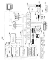
DVDからデータをレンダリングすることができる例示的なシステム200を示す図2を検討されたい。システム200には、DVD206からデータを読み取るソースコンポーネント204と通信するアプリケーション202が含まれる。DVDから読み取られるデータには、エンコードされ、一緒に多重化されたオーディオデータおよびビデオデータが含まれる。ソースは、DVDからデータを読み取る時に、データパケットにタイムスタンプを適用し、このタイムスタンプは、レンダリングのためにパケットを同期化し、スケジューリングするのに使用される。パケットは、デマルチプレクサ208に供給され、デマルチプレクサ208は、パケットを異なる構成部分すなわち、オーディオパケット、ビデオパケット、および存在する場合にサブピクチャ(subpicture)パケットに分割する。パケットは、その後、デマルチプレクサによって、ビデオデコーダ210(ビデオパケットのデコード用)、オーディオデコーダ212(オーディオパケットのデコード用)、およびサブピクチャデコーダ214(サブピクチャパケットのデコード用)などの関連するデコーダに供給される。パケットのそれぞれが、関連するタイミング情報を有し、このタイミング情報によって、パケットがレンダリングされると思われる時が定義される。さまざまなデコーダは、関連するパケットを圧縮解除し、個々のデータサンプルまたはデータパケット(パケットのタイムスタンプを含む)を、ビデオレンダラ216およびオーディオレンダラ218などの適当なレンダラに送る。
【0015】
システム200には、通常は、グローバルクロック220も含まれ、グローバルクロック220は、そのタイムスタンプがグローバルクロックによって示される時刻と一致するデータサンプルをレンダリングする時を確認するために、さまざまなレンダラによって使用される。
【0016】
ユーザが、アプリケーション202を介して、異なる、おそらくはより速いレートでデータサンプルをレンダリングさせることを望むことを示すと仮定する。
【0017】
順方向レート変更を調整する過去の手法は、グローバルクロック220を操作することである。すなわち、データを通常のレートの2倍の速度で再生したい場合には、グローバルクロックの速度を操作することによって、望みのレート変更を実施することができる。この手法に関する問題は、オーディオレンダラが、周波数シフトおよびひずんだオーディオ出力(ユーザの経験の質が下がる)に関連する問題を経験する可能性があることである。さらに、ビデオレンダラが、クロック変更に従うことを試みる時に、ビデオレンダラの処理が遅れ、これによって、レンダラが、追い付こうとしてサンプルを捨てる結果になる可能性がある。この全体的な結果は、オーディオの周波数シフトと、ビデオのタグアンドプル(tug−and−pull)である。サブピクチャ成分(ビデオレンダラに送られるデータがそれから生じる可能性がある)も、グローバルクロック変更に関連する問題を有する可能性があり、したがって、たとえばサブピクチャが不適切な時刻にまたは不適切なビデオに関連してレンダリングされることになる可能性がある。したがって、出力の品質が、大きく劣化する可能性がある。
【0018】
順方向レート変更に対処することを試みるもう1つの手法は、ソース204に、デマルチプレクサ208に通知させ、デマルチプレクサ208に、ビデオデコーダ210に通知させて、適当なレート変更を行うことである。デコーダ210は、サンプルのタイムスタンプに対するスケーリング動作を行って、異なるレートでビデオ再生を行うことができる。この手法に関する問題は、ビデオデコーダ210、オーディオデコーダ212、およびサブピクチャデコーダ214が、同一の技法およびアルゴリズムを使用してサンプルを処理することの保証がないことであり、これは、異なるデコーダが異なるベンダ製である場合に特にそうである。したがって、レート変更が、わずかに異なる速度で行われる可能性があり、これによって、ビデオとオーディオがずれ始めることになる可能性がある。さらに悪いことに、サブピクチャが、同期化されなくなる可能性があり、これによって、誤った時にサブピクチャが表示される可能性がある。
【0019】
さらに、この2つの手法は、順方向再生されるビデオに関してのみ実際に使用され、逆方向再生されるビデオには使用されなかった。これらの過去の手法を使用すると、実際には、ビデオを逆方向に再生するようにビデオレンダラに伝える方法がなかった(かつ、現在もない)。ビデオレンダラは、通常は、ビデオをディスクから読み取る方法を制御できず、それに関する知識を有しない。
【0020】
【発明が解決しようとする課題】
本発明の目的は、レンダリング可能なディジタルデータを処理する改善された方法およびシステムを提供することである。
【0021】
【課題を解決するための手段】
さまざまな方法およびシステムによって、ビデオデータ、オーディオ/ビデオデータ、オーディオ/ビデオ/サブピクチャデータ、および類似物などのディジタルデータを、順方向と逆方向の両方での再生を可能にする形で処理できるようにする。さまざまな実施形態は、ユーザの経験を強化できる形での再生レート変更の処理にも対処する。
【0022】
【発明の実施の形態】
概要
下で説明するさまざまな方法およびシステムによって、ビデオデータ、オーディオ/ビデオデータ、およびオーディオ/ビデオ/サブピクチャデータなどのディジタルデータを、順方向と逆方向の両方でのスムーズな再生を可能にする形で処理できるようになる。さらに、再生レート変更を、ユーザの経験を強化する形で処理することができる。
【0023】
例示的なコンピューティングシステム
図3に、下で説明するシステムおよび関連する方法を実施することができる適切なコンピューティング環境300の例を示す。
【0024】
コンピューティング環境300は、適切なコンピューティング環境の1つの例にすぎず、メディア処理システムの使用の範囲または機能性に関する制限を暗示することを意図されたものではない。また、コンピューティング環境300を、例示的なコンピューティング環境300に示された任意のコンポーネントまたはその組合せに対する依存性または要件を有するものと解釈してもならない。
【0025】
説明されるさまざまな実施形態は、多数の他の汎用または特殊目的のコンピューティングシステム環境またはコンピューティングシステム構成と共に動作することができる。メディア処理システムと共に使用するのに適する可能性がある周知のコンピューティングシステム、コンピューティング環境、および/またはコンピューティング構成の例に、パーソナルコンピュータ、サーバコンピュータ、シンクライアント、シッククライアント、ハンドヘルドデバイス、ラップトップデバイス、マルチプロセッサシステム、マイクロプロセッサベースのシステム、セットトップボックス、プログラマブル民生用電子機器、ネットワークPC、ミニコンピュータ、メインフレームコンピュータ、上記のシステムまたはデバイスのいずれかを含む分散コンピューティング環境、および類似物が含まれるが、これに制限はされない。
【0026】
いくつかの実施形態で、このシステムおよび関連する方法を、コンピュータによって実行されるプログラムモジュールなどのコンピュータ実行可能命令の全般的な文脈で説明することができる。一般に、プログラムモジュールには、特定のタスクを実行するか特定の抽象データ型を実施する、ルーチン、プログラム、オブジェクト、コンポーネント、データ構造などが含まれる。これらの実施形態は、通信ネットワークを介してリンクされたリモート処理デバイスによってタスクが実行される分散コンピューティング環境でも実践することができる。分散コンピューティング環境では、プログラムモジュールを、メモリストレージデバイスを含むローカルおよびリモートの両方のコンピュータ記憶媒体に配置することができる。
【0027】
図3に示された例の実施形態によれば、コンピューティングシステム300は、1つまたは複数のプロセッサまたは処理ユニット302、システムメモリ304、およびシステムメモリ304を含むさまざまなシステムコンポーネントをプロセッサ302に結合するバス306を含むものとして図示されている。
【0028】
バス306は、メモリバスまたはメモリコントローラ、周辺バス、accelerated graphics port、およびさまざまなバスアーキテクチャのいずれかを使用するプロセッサバスまたはローカルバスを含む、複数のタイプのバス構造のいずれかの1つまたは複数を表すことを意図されている。制限ではなく例として、そのようなアーキテクチャに、Industry Standard Architecture(ISA)バス、マイクロチャネルアーキテクチャ(MCA)バス、Enhanced ISA(EISA)バス、Video Electronics Standards Association(VESA)ローカルバス、およびメザニンバスとも称するPeripheral Component Interconnect(PCI)バスが含まれる。
【0029】
コンピュータ300には、通常はさまざまなコンピュータ可読媒体が含まれる。そのような媒体は、コンピュータ300によってローカルにおよび/またはリモートからアクセス可能なすべての使用可能媒体とすることができ、これには、揮発性および不揮発性の両方の媒体、取外し可能および取外し不能の両方の媒体が含まれる。
【0030】
図3では、システムメモリ304に、ランダムアクセスメモリ(RAM)310などの揮発性の形のコンピュータ可読媒体および/または読取専用メモリ(ROM)308などの不揮発性メモリの形のコンピュータ可読媒体が含まれる。起動中などにコンピュータ300内の要素の間で情報を転送するのを助ける基本ルーチンを含む基本入出力システム(BIOS)312が、通常はROM308に保管される。RAM310には、通常は、処理ユニット302から即座にアクセス可能かつ/または処理ユニット302によって現在操作されるデータおよび/またはプログラムモジュールが含まれる。
【0031】
コンピュータ300に、さらに、他の取外し可能/取外し不能の揮発性/不揮発性のコンピュータ記憶媒体を含めることができる。例としてのみ、図3に、取外し不能不揮発性磁気媒体(図示せず、通常は「ハードドライブ」と称する)から読み取り、それに書き込むハードディスクドライブ328、取外し可能不揮発性磁気ディスク332(たとえば、「フロッピー(登録商標)ディスク」)から読み取り、それに書き込む磁気ディスクドライブ330、およびCD−ROM、DVD−ROM、または他の光学媒体などの取外し可能不揮発性光ディスク336から読み取り、それに書き込む光ディスクドライブ334を示す。ハードディスクドライブ328、磁気ディスクドライブ330、および光ディスクドライブ334は、それぞれ、1つまたは複数のインターフェース326によってバス306に接続される。
【0032】
ドライブおよびそれに関連するコンピュータ可読媒体は、コンピュータ300の、コンピュータ可読命令、データ構造、プログラムモジュール、および他のデータのストレージを提供する。本明細書で説明する例示的実施形態では、ハードディスク328、取外し可能磁気ディスク332、および取外し可能光ディスク336が使用されるが、当業者は、磁気カセット、フラッシュメモリカード、ディジタルビデオディスク、ランダムアクセスメモリ(RAM)、読取専用メモリ(ROM)、および類似物など、コンピュータによってアクセス可能なデータを保管することができる他のタイプのコンピュータ可読媒体も、例示的オペレーティング環境で使用できることを諒解されたい。
【0033】
制限ではなく例としてオペレーティングシステム314、1つまたは複数のアプリケーションプログラム316(たとえば、マルチメディアアプリケーションプログラム324)、他のプログラムモジュール318、およびプログラムデータ320を含む複数のプログラムモジュールを、ハードディスク328、磁気ディスク332、光ディスク336、ROM308、またはRAM310に保管することができる。ユーザは、キーボード338およびポインティングデバイス340(「マウス」など)などの入力デバイスを介してコンピュータ300にコマンドおよび情報を入力することができる。他の入力デバイスに、オーディオ/ビデオ入力デバイス353、マイクロホン、ジョイスティック、ゲームパッド、衛星放送用パラボラアンテナ、シリアルポート、スキャナ、または類似物(図示せず)を含めることができる。これらおよび他の入力デバイスは、バス306に結合される入力インターフェース342を介して処理ユニット302に接続されるが、パラレルポート、ゲームポート、またはuniversal serialbus(USB)などの他のインターフェースおよびバス構造によって接続することができる。
【0034】
モニタ356または他のタイプのディスプレイデバイスも、ビデオアダプタまたはビデオ/グラフィックスカード344などのインターフェースを介してバス306に接続される。モニタのほかに、パーソナルコンピュータには、通常は、スピーカおよびプリンタなどの他の周辺出力デバイス(図示せず)が含まれ、これらの周辺出力デバイスを、出力周辺インターフェース346を介して接続することができる。
【0035】
コンピュータ300は、リモートコンピュータ350などの1つまたは複数のリモートコンピュータへの論理接続を使用して、ネットワーク化された環境で動作することができる。リモートコンピュータ350には、通常は、コンピュータに関して本明細書で説明する要素および特徴の多数またはすべてを含めることができる。
【0036】
図3からわかるように、コンピューティングシステム300は、ローカルエリアネットワーク(LAN)351および一般的な広域ネットワーク(WAN)352を介して、リモートデバイス(たとえば、リモートコンピュータ350)に通信的に結合される。そのようなネットワーキング環境は、オフィス、企業全体のコンピュータネットワーク、イントラネット、およびインターネットでありふれたものである。
【0037】
LANネットワーキング環境で使用される時には、コンピュータ300は、ネットワークインターフェースまたはネットワークアダプタ348を介してLAN351に接続される。WANネットワーキング環境で使用される時には、コンピュータ300に、通常はモデム354または、WAN352を介する通信を確立する他の手段が含まれる。モデム354は、内蔵または外付けとすることができるが、ユーザ入力インターフェース342または他の適当な機構を介してシステムバス306に接続することができる。
【0038】
ネットワーク化された環境では、パーソナルコンピュータ300に関して図示されたプログラムモジュール、またはその一部を、リモートメモリストレージデバイスに保管することができる。制限ではなく例として、図3に、リモートコンピュータ350のメモリデバイスに常駐するものとしてリモートアプリケーションプログラム316を示す。図示のネットワーク接続が、例示的であり、コンピュータの間で通信リンクを確立する他の手段を使用することができることを諒解されたい。
【0039】
第1の例示的実施形態−逆方向再生/レート変更
図4に、あるタイプのメディアで実施されるディジタルデータを処理し、その結果、そのデータを逆方向にレンダリングできるようにする第1の実施形態を概略的に示す。この例では、システムに、ユーザが、処理されレンダリングされる特定のディジタルメディアと対話できるインターフェースを提供するアプリケーション400が含まれる。このシステムには、レンダリングされるデータを読み取るための1つまたは複数のソース402、レンダリングされるデータをデコードまたは圧縮解除する1つまたは複数のデコーダ406、およびデータをレンダリングする1つまたは複数のレンダラ408も含まれる(各タイプのコンポーネントは1つだけ図示)。レンダラ408によってレンダリングされるディジタルメディアは、メディア410で提供され、メディア410には、この例では、DVDなどのディスクが含まれる。しかし、どのタイプのメディアでも、ディジタルメディアを保管するのに使用することができる。ソース、デコーダ、およびレンダラが、別々の個々のコンポーネントとして図示されているが、それぞれの機能性をより集積された形で提供できることを諒解されたい。
【0040】
メディア410は、通常は、レンダリングすることができる大量のデータを保持する。データは、通常は、論理ユニットに編成される。論理ユニットは、ブロックとして表される。用語「ブロック」は、特定のタイプのデータまたはメディアを指定することを意図されたものではない。そうではなく、この用語は、この実施形態がその下で動作する原理を示すために使用される。したがって、図示されるブロックは、通常はキーフレームから始まるセクションにデータを分割する異なるタイプまたは異なるフォーマットのデータを表すことができる。たとえば、ブロックに、MPEG−1フォーマットまたはMPEG−2フォーマットでデータをフォーマットするのに使用されるGOPを含めることができる。ブロックは、DVDでデータをフォーマットするのに使用されるものなどのVOBUを表すこともできる。
【0041】
そのようなブロックの特性の1つが、個々のブロックが、ブロックの副コンポーネントを表す副部分からなることである。したがって、ブロックがGOPを表す場合には、個々の副部分に、1つのIフレームおよび1つまたは複数のPフレームまたはBフレームを含めることができる。各ブロックの副部分は、各ブロック内で数字によって示される。たとえば、ブロック1は、副部分1、2、3、および4からなり、これらの副部分のそれぞれが、ビデオフレームを表す。
【0042】
ブロックは、ブロックとして処理されるために下流コンポーネントに渡される、より小さい独立の副ブロックに分解することもできる。たとえば、DVDでは、VOBUに、複数のGOPを含めることができる。VOBUブロックを、それぞれが1つのGOPを含む複数の副ブロックに分解することができる。これは、コンテンツを逆方向に再生する時に有用である。というのは、より大きいブロックを、より小さいブロックに分解でき、これらの小さいブロックの順序が、下流に送られる時に逆転されるからである。新しい副ブロックのそれぞれについて新しいタイムスタンプを計算する必要がある(図14参照)。
【0043】
ユーザが、アプリケーション400を介して、特定のデータ(ビデオデータなど)を逆方向に再生することを望むことを示す時に、アプリケーション400は、逆方向再生が意図されていることをソース402に通知する。アプリケーションは、通常は、逆方向再生が行われる時間範囲またはソース時間も示すことができる。ソース402が、逆方向再生が行われる時間期間に入った時に、ソースは、相対ソース時間内のデータのブロックを逆に読み取る。
【0044】
たとえば、図4を検討されたい。メディア410に、3つの個々のブロック(ブロック1、ブロック2、およびブロック3として示されている)がグループAとして含まれることが図示されていることに留意されたい。実際には、メディア410に、図示されたものより多数のブロックが含まれる。しかし、この例では、ユーザが、グループAのブロックを逆方向に再生することを望むことを、アプリケーション400を介してソース402に示したと仮定する。
【0045】
ソースは、メディア410からデータを読み取る際に、ソース時間を記憶し、ソース時間がブロック1から3と一致する時に、ブロック1から3を逆の順序で読み取る。具体的に言うと、ブロック3が最初に読み取られ、その後、ブロック2、その後、ブロック1が読み取られる。したがって、ソース402の左で、グループBを定義するために、読み取られるブロックの順序付けがブロック3/ブロック2/ブロック1であることに留意されたい。その後、ソース402は、1つまたは複数のフラグをブロックに追加して、それらが逆方向再生を意図されていることを示す。具体的に言うと、スタートフラグが、ブロック3に追加され、エンドフラグが、ブロック1に追加されることに留意されたい。フラグの任意の適切な配置を使用して、逆方向再生に関してブロックを指定することができる。たとえば、フラグを、各ブロックの終りに追加することができる。ソース402は、ブロックにタイムスタンプを追加することによってブロックを処理することもできる。これは、各ブロックのソース時間を、レンダリングアクティビティをスケジューリングするのにレンダラによって使用される単調増加するタイムスタンプにマッピングすることによって行うことができる。
【0046】
その後、各ブロックが、ソース402によってデコーダ406に供給される。デマルチプレクサまたはスプリッタをソースとデコーダの間に入れることができるが、図を簡単にするために図示されていないことを諒解されたい。したがって、たとえば、ブロック3をデコーダ406に供給し、その後、ブロック2を、最後にブロック1を供給することができる。その代わりに、ソースが、ブロックを事前に解析し、処理またはデコード/圧縮解除のためにデコーダに逆の順序で一時にブロックのより小さい副ブロックを送ることができる。これによって、デコーダに伝搬されるブロックのサイズが減る。
【0047】
デコーダ406は、ブロックを受け取る時に、左から右へとデコードする。しかし、ブロックのフラグによって、デコーダに、ブロックをデコードし、レンダラ408に発行されるブロックの副部分(フレーム)の順序を逆転しなければならないことが示される。具体的に言うと、デコーダ406は、ブロック3を受け取り、普通にそのブロックをデコードし、他のブロックを処理している間、デコードされたブロック部分をバッファリングすることができる。デコーダ406は、ブロック2および1を同様に処理する。デコーダが、エンドフラグに達した時に、デコーダは、逆方向再生が行われる特定のブロックシーケンスが定義済みであることを知る。デコーダは、ブロック副部分のタイムスタンプを逆転することができ、そのブロック副部分をレンダラ408に逆の順序で発行することができる。発行されたブロック副部分は、グループCとして表される。
【0048】
上記からわかるように、レンダラは、ストリームが順方向再生される場合に有する順序に対して逆転されたデータのストリームを受け取る。レンダラは、レンダリングのためにストリームをスケジューリングすることができる。レンダラは、ここで、ストリームが逆方向で再生されることを知らない。というのは、その詳細が、ソースコンポーネントおよびデコーダコンポーネントの中に閉じこめられているからである。
【0049】
ユーザが、再生レートを変更するためにレート変更を実施することを望むと仮定する。この実施形態では、レート変更を下記のように実施することができる。ユーザが、通常すなわち1倍速より高速または低速のレートでデータをレンダリングさせることを望むと仮定する。レート変更を、アプリケーション400を介してソース402に通信することができる。レート変更情報を、ソースからデコーダ406に供給することができ、その結果、レート変更処理を、デコーダによって実行することができる。この実施形態では、デコーダが、それが処理するサンプルまたはブロック副部分のタイムスタンプを操作することによって、レート変更処理を実行することができる。たとえば、サンプルのグループが、1倍速でレンダリングされ、t1からt4まで伸びるタイムスタンプを有する場合に、タイムスタンプをt1−t4からt1−t2(ただし、t2−t1=(t4−t1)/2)に変更することによって、そのようなサンプルを2倍速でレンダリングすることができる。
【0050】
図5は、一実施形態による方法のステップを説明する流れ図である。この方法は、適切なハードウェア、ソフトウェア、ファームウェア、またはその組合せで実施することができる。図示の例では、この方法を、図4に図示されそれに関して説明されたシステムに関連して実施することができる。
【0051】
ステップ500で、逆方向再生が望まれることの指示を受け取る。このステップは、逆方向再生が望まれることの通信または呼出しをソフトウェアから受け取ることによって実施することができる。この通信に、逆方向再生が望まれるソース時間の範囲を含めることができる。ステップ502で、1つまたは複数のデータブロックを配置して、再生順序を定義する。このステップは、指示されたソース時間範囲に対応するブロックを逆方向で読み取ることによって実施することができる。これを行うことができる方法の1つの例を、上で示した。ステップ504で、1つまたは複数のフラグをデータブロックに関連付ける。このフラグは、当の1つまたは複数のブロックが、逆方向再生の対象であることを示すことを意図されたものである。逆方向再生スタートフラグおよび逆方向再生エンドフラグを、当のブロックに関連付けることができる。
【0052】
ステップ506で、ブロックを個々のブロック副部分にデコードし、さらに、所望の逆方向再生に従ってブロック副部分を処理することができる。これには、たとえば、所定の時間期間の間のブロック副部分のバッファリングを含めることができる。たとえば、ブロック副部分を、逆方向再生を意図されたブロック副部分のすべてがデコードされるまでバッファリングすることができる。その代わりにまたはそれに追加して、ブロック副部分を、所定の数または量の副部分がバッファリングされるまでバッファリングすることができる。バッファリングされたデコードされたデータを、圧縮ソースデータと共に使用して、逆方向再生ストリームを完全に再生成することもできる。さらに、ブロック副部分を処理して、それに関連するタイムスタンプを操作することもできる。これには、個々の副部分のタイムスタンプの有効な順序を逆転することを含めることができる。これには、要求される可能性があるレート変更に起因するすべてのタイムスタンプ処理を含めることもできる。そのようなタイムスタンプ処理に、タイムスタンプの値の変更を含めることができる。
【0053】
ステップ508で、逆の順序でブロック副部分を発行する。このステップでは、ステップ504のフラグを使用して、ブロック副部分を逆の順序で発行しなければならないことを示すことができる。したがって、たとえば、デコーダ406(図4)が、ブロック副部分を処理する時に、フラグの存在によって、デコーダがブロック副部分を逆の順序で発行しなければならないことを示すことができる。デコーダは、ブロック副部分を逆の順序で発行することができる。これを行う方法の1つの例を、上で示す。ステップ510で、副部分が発行されたのと逆の順序で、発行されたブロック副部分をレンダリングする。
【0054】
同一のアルゴリズムを適用して、ブロックを副ブロックに分割することができ、この副ブロックは、ソースまたはデコーダなどの上位コンポーネントが使用することができる。効果的に、ソースは、ビデオ全体を副ブロック(DVDの場合にはVOBU)に分割し、それらを、逆転されたタイムスタンプと共に逆の順序で発行する。デコーダは、VOBUを読み取り、キャッシングし、その後、キャッシングされたデータを逆の順序で発行することによって、VOBUをGOPブロックに分割してレンダラに渡すことができる。
【0055】
上で説明した処理およびシステムは、デコードされたブロック副部分をバッファリングするために、より多くのメモリの要件を有する。しかし、この手法の長所に、下記が含まれる。第1に、いくつかのシステムは、効果的に位置において後ろにジャンプし、複数のフレームを順方向に再生し、その後、もう一度位置において後ろにジャンプし、複数のフレームを順方向に再生する処理を繰り返すことによって、逆方向再生の達成を試みる。この処理は、作業が反復されるので計算的に極度に非効率的になる可能性があり、通常はユーザの経験の質が低下する。他の手法では、一時に1データブロックだけが操作される。
【0056】
上のシステムおよび方法では、実際に、逆方向再生が望まれる時に複数のブロックの順序を変更することができる。さらに、フラグを使用することによって、システムが、個々のブロック副部分またはフレームを逆の順序で実際にレンダリングできるようになる。また、ブロック副部分のタイムスタンプを操作することによって、レート変更をスムーズに提供することができる。他の長所は、当業者に明白であろう。
【0057】
性能の利点として、上で説明した方法およびシステムは、グラフィックスプロセッサ内のさまざまなパイプライン化されたビデオアクセラレーション技法を利用することができる。これは、デコーダについて特にそうである。これによって、データパイプラインが、継続的に効率的に動作できるようなり、初期化スタートアップコストを防ぐことができる。さまざまなパイプライン化されたビデオアクセラレーション技法が、米国特許出願第09/839682号(発明の名称:拡張可能なマルチメディアアプリケーションプログラムインターフェイスおよび関連する方法、出願日:2001年4月20日、その開示内容は参照されることによってこの明細書に組み込まれる)。
【0058】
第2の例示的実施形態−逆方向再生/レート変更
上で説明した実施形態では、デコーダが、アプリケーションからのすべてのレート変更要求ならびにすべての逆方向再生要求を処理するように構成された。しかし、レンダリング可能なデータを処理するシステムのチェーンまたは処理パイプラインに、より多くのコンポーネントが含まれる可能性がある。たとえば、処理パイプラインの1タイプを、フィルタグラフ(filter graph)と称する。フィルタグラフは、フィルタ(または処理ユニット)の有向ネットワーク(directed network)である。フィルタグラフには、最終的にレンダリングされるデータを処理するように構成された多数の異なるタイプのフィルタを含めることができる。ソースフィルタおよびデコーダフィルタのほかに、そのようなフィルタグラフに、変換フィルタ、効果フィルタ、ネットワークリンク、分析フィルタ、および類似物を含めることができる。
【0059】
再生およびレート変更処理を、システム、パイプライン、またはフィルタグラフにまたがって分散させることが有利になる可能性がある。この理由の1つが、実装の柔軟性が高まること、ならびに、オープンで拡張可能なアーキテクチャである。たとえば、ユーザが、既にデコーダによって処理されたが、レート変更を行うことができない下流コンポーネントでキューイングされているサンプルのレート変更を要求する場合に、すべてではないにしてもほとんどの現在のシステムが、通常は、そのレート変更を無視する。
【0060】
通常、レート変更は、2つの形の1つで行うことができる。第1に、ユーザは、レート変更を現在または今、行うことを要求することができる。おそらく、ユーザは、再生レートに影響する、UI内のスライダを操作する。第2に、レート変更を、ソースコンテンツ内の所与の位置でスケジューリングすることができる。たとえば、おそらく、ユーザは、ソース時間00:00:05から開始される2倍速へのレート変更が望ましいことを示す。この2つのシナリオは、根本的に異なる。第1のシナリオは、要求のタイミングおよびその瞬間の処理パイプラインの状態のゆえに、より困難なシナリオである。ソースコンテンツが、既にソースによって読み取られ、パイプラインの次のコンポーネントに転送されている可能性がある。第2のシナリオは、レート変更が行われる場所がわかっており、したがって、レート変更を前もってスケジューリングすることができるので、より容易な問題である。
【0061】
上で注記したように、ソースは、データを処理する時に、特定のメディアからデータを読み取り、データに関連するソース時間を、レンダリングのスケジューリングに使用されるタイムスタンプにマッピングする。たとえば、次の表に、1倍速での順方向再生についてソースによって実行されるマッピング動作の表現を示す。
【0062】
【表1】

上の表では、00:00:01から00:00:05に対応するソース時間が、レンダリングされる特定のフレームと一致するタイムスタンプにマッピングされる。たとえば、00:00:01は、フレーム1に対応するタイムスタンプにマッピングされ、00:00:02は、フレーム2に対応するタイムスタンプにマッピングされるなどである。したがって、1倍速での順方向再生に関して、1対1マッピング関係がある。
【0064】
逆方向再生の要求がある時に、マッピング動作が、多少変更される。この例では、ソースで、まだソース時間がタイムスタンプにマッピングされる。しかし、ソースは、タイムスタンプの連続的な単調増加するストリームを提供するだけではなく、逆方向再生要求も考慮に入れた形でそれを行う。たとえば、下の表に、ソース時間範囲00:00:01から00:00:05までの、1倍速での逆方向再生に関するマッピング動作を示す。
【0065】
【表2】
ソース時間が、逆方向再生を反映して再割り当てされているが、対応するタイムスタンプが、単調増加し続けることに留意されたい。したがって、レンダラは、このデータサンプルを受け取る時に、逆方向再生に影響するようにレンダリングをスケジューリングする。
【0067】
ソースコンテンツの別の部分へのジャンプがあると仮定する。おそらく、ソースコンテンツは、ソース時間範囲00:00:01から00:00:05までについてレンダリングされ、その後、ソース時間範囲00:00:20から00:00:24までへのジャンプがある。この場合に、マッピング動作によって、下記の単調増加するタイムスタンプのストリームが作られる。
【0068】
【表3】
したがって、この実施形態で、ソースの責任は、アプリケーションから要求を受け取り、ソースデータの位置(すなわちソース時間)に基づくコンテキストを単調増加する出力タイムスタンプにマッピングすることである。それを行う際に、データの連続的なストリームを、レンダリングのためにレンダラに供給することができる。これは、他のコンポーネントが、タイムスタンプおよび特定のプロセスのどこにいるかを記憶する必要がないという点で、他のコンポーネント、特にレンダラの観点から、有利である。そうではなく、他のコンポーネントは、単純に、タイムスタンプの線形ストリームを有するサンプルを受け取り、処理することができる。
【0070】
ソースでの処理を容易にするために、ソースが、レート変更を行った時およびそのレート変更が将来に発生するイベントのリストのどこにマッピングされたかのヒストリを維持することができる。その場合に、アプリケーションが、特定の時でのレート変更の要求を始める場合に、ソースは、過去にレート変更をどのように編成したかを知っている。ソースは、レート変更に関連するソースコンテンツが、既に処理のために下流コンポーネントに渡されたかどうかも知っている。すでに渡されている場合に、ソースは、たとえばレート変更要求を下流コンポーネントに渡し、これらのコンポーネントにレート変更実施の関連処理を行わせることによって、レート変更を実施させることを試みるステップを行うことができる。他の手法では、既にソースから出たソースコンテンツに関するそのようなレート変更要求は、単純に削除されていた。
【0071】
コンポーネント能力を確かめるためのパイプラインへの照会
上および下で説明する実施形態のいくつかの有利な特徴の1つが、ソースが、コンポーネントの機能を確かめるために処理パイプライン内のコンポーネントに照会する能力を有することである。たとえば、ソースは、デコーダなどのコンポーネントに照会して、そのコンポーネントが逆再生をサポートするかどうか、サポートされる再生レート、最大再生レート、最小再生レート、および類似物を確かめることができる。それを行うことによって、ソースは、ソースデータを読み取る方法と、いくつかの場合に、他のコンポーネントに送るソースデータのフォーマットを、知的に判断できるようになる。
【0072】
一例として、下記を検討されたい。レート変更を実施し、それを知的に行うために、ソースが、パイプライン全体またはフィルタグラフによってサポートされる最大レートを知ることが有利になる可能性がある。これは、順方向再生と逆方向再生の両方にあてはまる可能性がある。この実施形態では、1つまたは複数のパイプラインコンポーネントに、ソースが照会することのできるインターフェース(単に呼出し可能なメソッドの集合である)が与えられる。パイプラインを構成するかインスタンス化する時に、ソースは、1つまたは複数のインターフェースに照会して、コンポーネントの機能を確かめることができる。たとえば、ソースは、コンポーネントに照会して、それらのどれかが逆方向再生をサポートするかどうかを確かめることができる。そうでない場合には、これによって、ソースが、逆方向再生をサポートしない、より単純なモードに入り、それをアプリケーションに示すようにすることができ、これによって、アプリケーションが、よりスマートなUIをユーザに提示するようになる。これには、たとえば、ブロック全体を逆に読み取り、適当なフラグを用いてタグを付けるのではなく(いずれにせよデコーダが操作することはできない)、逆の順序でブロックのキーフレームを読み取ることを含めることができる。さらに、ソースは、サポートされる再生レートを確かめるために照会することができる。これを知ることによって、ソースは、その処理を適応させて、パイプラインを圧倒しないことを保証することができる。たとえば、特定の再生速度が、パイプラインによってサポートされない場合に、ソースは、パイプラインによるさらなる処理のために、あるブロック部分だけ(たとえばIフレームだけ)を送ることができる。これは、パイプラインが、効率的に処理できないデータの重荷を過度に負わされないことを保証すると同時に、できる限り要求された再生レートに近いレンダリングされたディスプレイを提供するのを試みるのに役立つ。
【0073】
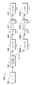
照会処理を実施する方法の1つは、次の通りである。ソースは、最初に始動されるかインスタンス化される時に、直接にまたは間接的に、パイプラインのすべてのコンポーネントに、その機能、たとえば最大順方向レートおよび最大逆方向レートを照会する。これを行う方法の1つが、ソースが、最初の下流コンポーネントに照会し、最初の下流コンポーネントが、その最初の下流コンポーネントに照会し、以下同様に繰り返すことである。一例として、図6を検討されたい。図6には、ソース602、デマルチプレクサ604、デコーダ606および606a、コンポーネント608、608a、610、および610a(任意の適当なコンポーネントとすることができる)、およびレンダラ612および612aを含む例示的なパイプライン600が示されている。この場合に、ソース602が、デマルチプレクサ604に照会し、デマルチプレクサ604が、デコーダ606および606aに照会し、以下同様である。その後、照会結果を、パイプラインの上流に返すことができる。
【0074】
この例では、ソースが、さまざまなコンポーネントの最大順方向再生レートに関心を持つと仮定する。この例では、コンポーネントの最大レートのそれぞれが、そのコンポーネントの真下に示されている。したがって、たとえば、レンダラ612の最大レートは、2倍速であり、レンダラ612aの最大レートは、3倍速である。ソースがパイプラインの最大レート全般に関して判断を行える形は、2つある。まず、ソースは、保守的な形で、さまざまなコンポーネントのすべてのレートの最小値を単純にとることができる。したがって、この特定の例では、すべてのレートの最小値は2倍速である。したがって、この知識から、ソースは、2倍速未満の要求されたレートのすべてを、有意な量のデータを除去する必要なしにスムーズにレンダリングできると仮定することができる。第2の、より積極的な手法は、さまざまなコンポーネントの間に乗法的効果があると仮定することである。たとえば、第1のコンポーネントが2倍速をサポートでき、その下流のコンポーネントが3倍速をサポートできる場合に、これらのコンポーネントが一緒になって提供できる最大レート変更は、6倍速である。したがって、この図で、レンダラ612は、コンポーネント610によって照会される時に、2倍速(コンポーネントの間の括弧内に示されている)の再生レートを報告する。したがって、コンポーネント610は、乗法的効果のゆえに、4倍速の再生レートをコンポーネント608に報告することができる。同様に、コンポーネント608は、8倍速の再生レートをコンポーネント606に報告することができ、以下同様である。この例では、デマルチプレクサ604が、1倍速再生レートだけをサポートすると仮定する。デマルチプレクサ604は、ソース602に、2つの再生レートすなわち16倍速および32倍速を報告することができる。この手法によれば、ソースは、2つの再生レートうちの低い方すなわち16倍速を、全般的にスムーズな再生レートを達成するためにパイプラインによってサポートされる最大再生レートとして選択することができる。
【0075】
ソースが、パイプラインのレート能力(たとえば16倍速)を知ったならば、ソースは、要求されたレートが16倍速以下である時にデータブロック全体をパイプラインに供給できることを知り、そのデータが、このレートでレンダリングされる。ソースは、16倍速を超える要求されたレート変更について、より高いレートを提供することを試みるためになんらかの追加処理を行わなければならないことを知ることができる。これには、パイプラインによる処理のために切り捨てられたおよび/または選択的なブロックだけを送ることを含めることができる。このモードを、「スキャンモード」と称し、このモードでは、たとえば、キーフレームだけを、処理のためにソースによってパイプラインに送ることができる。
【0076】
図7は、一実施形態による方法のステップを説明する流れ図である。この方法は、適切なハードウェア、ソフトウェア、ファームウェア、またはその組合せで実施することができる。図示の例では、この方法を、図6に図示されそれに関して説明されたシステムに関連して実施することができる。
【0077】
ステップ700で、データ処理パイプラインを設ける。任意の適切なデータ処理パイプラインを設けることができる。適切なパイプラインには、通常は、なんらかのタイプのメディア(ディスクなど)からソースデータを読み取るか、データを個々のデータストリームに多重化解除するか、なんらかの形でデータをデコードし、処理するか、ユーザが楽しむためにデータをレンダリングする、1つまたは複数のコンポーネントが含まれる。これらの異なる機能性は、異なるコンポーネントによって実行される傾向があるが、そうである必要ない。
【0078】
ステップ702で、再生サポート機能の提供に関してコンポーネントに照会する。再生サポート機能の例には、再生レート(最大、最小、および/またはレートの範囲)、再正方向(順方向、逆方向)、および類似物が、制限なしに含まれる。ステップ704で、照会されたコンポーネントの下流にコンポーネントがあるかどうかを判定する。ある場合には、ステップ706で、次のコンポーネントに進み、ステップ702に戻って、そのコンポーネントに照会して、その再生サポート機能を提供する。追加の下流コンポーネントがない場合には、ステップ708で、再生サポート機能をデータ処理パイプラインの上へ報告する。
【0079】
このステップは、2つの異なる形で実施することができる。まず、上で注記したように、各コンポーネントの機能を、ソースに報告することができ、ソースは、その後、知的なデータ処理判断を行うことができる。たとえば、コンポーネントのそれぞれの再生レートをソースに報告することができ、その結果、ソースが、最小再生レートを選択できるようになる。第2に、コンポーネントのそれぞれの機能を、他のすべてのコンポーネントの機能に関して検討することができる。たとえば、特定のパイプラインまたは副パイプライン内のすべてのコンポーネントの再生レートを乗算することができ、その結果、パイプラインまたは副パイプラインによってサポートされる全体的な有効再生レートを確かめることができる。確かめられたならば、ソースは、上で注記したようにデータを処理する方法について知的な判断を行うことができる。
【0080】
上で説明した例では、すべての適切に構成されたコンポーネント(フィルタ)を、データマニピュレータ(data manipulator)と見なすことができる。すなわち、個々のコンポーネントが、データを部分的に処理し、データをどのように操作したかに関する適当なヒントを渡すことができる。次のコンポーネントは、さらに、所望の再生レートまたは方向の達成に向かってデータを処理することができる。
【0081】
必要であれば、たとえば、ソースが、デコーダに供給するデータの量を減らすと同時に、データに関するタイミング情報(レート変更など)を維持することができる。これによって、デコーダに、レート変更が望まれることのヒントが与えられる。デコーダは、ソースからデータを受け取ることができ、デコードのほかに、レート変更の達成を試みる形でそのデータを処理することができる。チェーン内のコンポーネントは、所望の再生の達成に対処する形でデータを処理するという選択肢を有することができ、あるいは、コンポーネントは、レート変更に関する情報と共にデータを次のコンポーネントに渡すことができる。そのような処理には、データブロック部分の逆転、逆方向再生要求を受け取った場合のタイムスタンプの再割り当て、およびデータからの関連するフラグの除去を含めることができる。
【0082】
したがって、この例では、ソースが、ブロックレベルでストリームを逆にし、逆方向再生が意図されていることを示すフラグを追加することができる。ブロックは、その後、下流の他のコンポーネントに伝搬される。コンポーネントは、逆方向フラグを有するデータに出会った時に、ブロックを別の下流のコンポーネントに渡すこと、または、データを処理して、たとえばフレームの順序を逆にし、フラグを除去し、データを次のコンポーネントにプッシュすることという選択肢を有する。最終的に、レンダラが、適当に増加するタイムスタンプを有する順方向ストリームに見えるものを受け取る。
【0083】
ソースから出たブロックのレート変更
上で説明した実施形態は、レート変更が所与の時刻に行われ、レート変更が実施されるデータブロックをソースがまだ読み取っていない時に良好に動作する。もう1つの状況があり、この場合には、上で簡単に述べたように、ソースがデータブロックを読み取り、かつ/または処理のために下流コンポーネントにブロックを渡した後に、レート変更要求が受け取られる。
【0084】
これから説明する実施形態では、処理をコンポーネントパイプラインまたはフィルタグラフにまたがって分散させることによって、柔軟性が強化される。具体的に言うと、アプリケーションは、特定の時刻またはソース時間にレート変更を実行するようにソースコンポーネントに要求することができる。その後、レート変更情報が、レート変更に関連するソース時間を有するデータサンプルがそのキューに含まれるコンポーネントに出会うまで、パイプラインに沿って伝搬される。そのコンポーネントは、レート変更要求をキューに入れることができ、その結果、レート変更が、そのサンプルについて処理されるようになる。対応するサンプルが、コンポーネントによって処理される時に、コンポーネントは、出力データ(たとえばサンプルのタイムスタンプ)の変更などの必要な処理をすべて実行することができる。さらなる処理が必要な場合には、コンポーネントは、レート変更要求(ならびにすべての他の有用な情報)を、各出力サンプルと共に渡すことができる。最終的に、レンダラが、サンプルを受け取り、レンダリングをスケジューリングすることができる。分散処理の一部として再生またはレート変更の処理を実施するようにレンダラを構成することもできることを諒解されたい。
【0085】
もう1つの重要な利点は、ソースのレート変更キューが、まだ送っていないか読み取っていないデータだけに制限されることである。キューの残りは、パイプラインに沿って分散され、このパイプラインは、ほとんどの場合に比較的短い。
【0086】
例として、下記を検討されたい。アプリケーションが、レート変更要求をソースに送る時に、ソースは、そのバッファを調べ、レート変更がそれに関して行われるデータが、バッファに置かれているかどうかを確かめる。ソースは、通常は、レート変更が行われるソース時間を記録することによってこれを行うことができる。ソースのバッファ内のデータが、レート変更が行われるソース時間より後の対応するソース時間を有する場合に、データサンプルは、既に下流コンポーネントに渡されている。ソースは、レート変更の対象になるデータを含むバッファを突き止めた場合に、レート変更情報をそのサンプルに関連付けることができる。
【0087】
すなわち、この実施形態によれば、すべてのデータサンプルに、(1)すべてのレート変更、(2)サンプルを再生しなければならない時間範囲、および(3)サンプルを順方向または逆方向のどちらで再生するかを定義するプロパティを含むリストが含まれる。このリストは、データサンプルと共に伝搬され、その結果、パイプライン内のコンポーネントが、過去に行われたすべてのレート変更のリストを維持する必要がなくなる。
【0088】
ソースが、そのバッファを検査し、レート変更が行われるサンプルが見つからない場合には、ソースは、レート変更要求を次の下流コンポーネントに送る。次のコンポーネントは、そのバッファを検査して、そのバッファにレート変更が行われるサンプルが含まれるかどうかを確かめることによって、同様の処理を実行する。コンポーネントが、適当なデータサンプルを見つけた場合には、そのコンポーネントは、サンプルを処理する時にレート変更情報をサンプルに追加するか、バッファを調べ、バッファ内のサンプルにレート変更情報をアタッチするのいずれかを行うことができる。この処理は、データパイプライン内の適切に構成されたコンポーネントによって実行することができる。
【0089】
図8は、一実施形態による方法のステップを説明する流れ図である。この方法は、適切なハードウェア、ソフトウェア、ファームウェア、またはその組合せで実施することができる。図示の例では、この方法を、図6に図示されそれに関して説明されたシステムに関連して実施することができる。
【0090】
ステップ800で、特定のソース時間に関するレート変更要求を受け取る。通常、レート変更要求は、アプリケーションから発し、ソースに渡される。レート変更要求の受け取りに応答して、ステップ802で、1つまたは複数のバッファを検査して、レート変更が行われる対応するデータサンプルが存在するかどうかを確かめる。検査されるバッファは、レート変更要求を受け取ったコンポーネントに関連するバッファである。サンプルが見つかる場合に(ステップ804)、ステップ806で、レート変更情報をサンプルにアタッチする。このステップは、2つの形で実施することができる。たとえば、レート変更情報を、サンプルがバッファにある間にサンプルにアタッチすることができる。これは、バッファが読取/書込キューである時に実施することができる。その代わりに、レート変更情報を、キャッシングし、サンプルがコンポーネントによって処理される時にサンプルにアタッチすることができる。このステップは、バッファが読取専用キューである時に実施することができる。
【0091】
その一方で、サンプルが、コンポーネントのバッファ内で見つからない場合には、ステップ808で、レート変更要求を次の下流コンポーネントに送る。ステップ810で、下流コンポーネントに関連するバッファを検査する。このステップは、レート変更要求を受け取ったコンポーネントによって実施することができる。サンプルが見つかる場合に(ステップ812)、この方法は、ステップ806に分岐することができる。その一方で、サンプルが見つからない場合には、ステップ814で、別の下流コンポーネントがあるかどうかを判定する。そうである場合には、この方法は、ステップ808に分岐し、レート変更要求を次のコンポーネントに送る。その一方で、追加の下流コンポーネントがない場合には、ステップ816で、レート変更要求を破棄する。おそらく、このステップは、レンダラによって実施される。レート変更要求の破棄は、レンダリングの出力レートに対する一時的な影響だけを有する。
【0092】
クリーンポイントがないデータのレート変更
多重化されたデータストリーム(ATSC MPEG2など)は、ビデオのキーフレームで位置合せされる二次ストリーム(secondary stream)を必ずしも有しない場合がある。これによって、コンテンツを、キーフレームによって区切られた別個のブロックに分割することを試みる時に問題が生じる。
【0093】
主ストリーム(primary stream)データのブロックに対応する任意の時間間隔の二次ストリームのデータを生成するには、下記の2つの解決策がある。
【0094】
1)トリミング
ソースは、すべてのストリームがその間隔に存在し、各ストリームがその間隔の開始タイムスタンプにスキップするように指示されるように、コンテンツを後ろ向きに検索する。
【0095】
2)フラグメント(fragment)の破棄
ソースは、主ストリームの先頭を探し、二次ストリームは、次のフレームの先頭までブロックフラグメントを破棄する。ストリームは、この間隔の間のデータがなく、不連続性を、間隔の先頭で送らなければならない。
【0096】
この時間間隔の後のデータを終了するために、切捨マーカー(truncation marker)を各ストリームに挿入する必要がある。図16に、二次ストリームについて余分なデータを読み取る方法と、ビデオストリーム間隔と一致するように二次ストリームを修正できる方法を示す。順方向再生について、フルフレームモード中の同一方向のレート変更は、クリーンポイントによって影響されない。
【0097】
順方向および逆方向のキーフレームスキャンモードについて、二次ストリームは、トリミングまたはフラグメント化を必要としない。大量のデータが、スキップされつつあるので、フラグメント化によってソースの設計が単純になるのでフラグメント化が好ましい場合がある。より複雑なシークを、機能強化として追加することができるが、これによって、シークおよびリーダとの対話に起因する性能コストが生じる場合がある。
【0098】
スムーズ逆方向再生について、トリミングされた二次ストリームが、連続的な逆方向オーディオのために必要である。しかし、ソースでのバッファリング要件(バッファ空間の2倍)および余分な高速デコード/破棄が、実現可能でない場合がある。しかし、オーディオデコードは、ビデオデコードと比較して比較的高速である。
ソースは、トリミング範囲の外のサンプルを破棄する責任を負う。
【0099】
実施例
上で説明した実施形態の諸態様を、具体的な実施例に関して説明する。下で説明する例が、例示を目的とし、請求される主題の応用分野を制限するものと解釈されてはならないことを理解されたい。
【0100】
これから説明する例では、下記のアーキテクチャ的態様が使用される。IRateChangeDataインターフェースは、各サンプルに対して設けられ、レート変更情報、フラグ、およびレート変更位置を維持するのに使用される。サンプルアロケータが、IRateChangeDataインターフェースをサポートするサンプルを作成する。インターフェースIRateChangeControl(通常は、フィルタの入力ピンまたはコンポーネントへの入力ピンにある)は、レート変更挿入を要求する::ScheduleRateChangeメソッドを提供する。このインターフェースは、順方向および逆方向の最大デコードレートを照会するメソッド::GetMaxRateもサポートする。メソッド::GetFurthestPositionは、まだ処理されていない最も遠いストリーム時間を照会し、その後でレート変更をスケジューリングできる時間間隔を判定するために提供される。
【0101】
もう1つのメソッド::ScheduleRateChangeNowでは、次の使用可能な時間位置でレート変更をスケジューリングすることと、実際の位置を返すことを要求する。このメソッドは、失敗したレート変更から回復することが最も少なく可能であるストリームに対して呼び出すことができる。::ScheduleRateChangeメソッドは、::ScheduleRateChangeNowによって返される位置を使用する他のストリームに対して呼び出すことができる。
【0102】
さらに、この例では、データフォーマットに関する下記の仮定にそって描かれる。スムーズな逆転、逆方向および順方向のスキャン再生(用語「スキャン」は、パイプラインまたはグラフによってサポートされる最大レートを超える再生速度に起因する切り捨てられた再生を表すのに使用される)について、通常は、ソースが、ストリームをクリーンポイントによって区切られるばらばらのブロックに分解できなければならない。クリーンポイントは、圧縮データ内で、すべてのストリームが同期化される位置である(すなわち、各ストリームが、新しいサンプルで同一のプレゼンテーションタイムスタンプで開始される)。たとえば、DVDソースでは、ソースブロックとしてVOBUが使用される。他のコンテンツフォーマットについて、ソースは、ストリームをGOPに分解する。というのは、ビデオおよびオーディオのストリームで、キーフレーム境界で新しいフレームが開始されるからである。一般的なMPEG−2コンテンツなどのクリーンポイントがないコンテンツについては、前の節の「クリーンポイントがないデータのレート変更」を参照されたい。
【0103】
レート変更要求のスケジューリングおよび処理に関して:
・フィルタは、IRateChangeControl::ScheduleRateChange要求をデコーダに送って、特定のソースタイムスタンプにミッドサンプル(mid−sample)レート変更を挿入する。デコーダは、レート変更位置を含むサンプルに出会うかどうかを判定する。そのタイムスタンプを既に処理したか、レート変更を処理しない場合に、デコーダは、入力ピンに対応させることによって制御される出力ピンのそれぞれにレート変更要求を渡す。
【0104】
・その代わりに、即時レート変更をスケジューリングするために、フィルタは、IRateChangeControl::ScheduleRateChangeNow要求をデコーダ(通常は、たとえば顕著な「音飛び」を引き起こすオーディオなど、データ消失から簡単には回復できないストリームのデコーダ)に送って、次の使用可能なソースタイムスタンプにミッドサンプルレート変更を挿入する。この要求は、あるコンポーネントが、このレート変更挿入要求を処理しなければならないと判断するまで、再帰的に下流に渡される。実際の位置が、ストリームを介して最初のフィルタまで返される。フィルタは、ScheduleRateChangeNow要求によって返されるタイムスタンプを使用して、他のストリームにレート変更要求を伝搬させる。
【0105】
・デコーダが要求を処理する時に、デコーダは、レート変更タイムスタンプを含むサンプルを受け取る時に、処理されるレート変更情報を内部的にキューイングする。サンプルに出会った時に、デコーダは、すべてのレート変更補間を実行し、レート変更情報を、出力サンプルのIRateChangeDataインターフェースにコピーする。
【0106】
・データストリーム内のタイムスタンプ情報は、ソースまたは中間フィルタによって直接には変更されない。各フィルタが、単純に、ストリームの内容を修正する。
【0107】
レート変更の計算に関して:
・ソースフィルタは、IRateChangeControl::GetMaxRateメソッドを使用して、デコーダの順方向および逆方向の最大再生ビットレートを照会する。グローバルフラグに真がセットされている場合には、フィルタは、対応する出力ピンおよびその最大内部レートの両方の最大レートを計算し、返さなければならない。
【0108】
IRateChangeDataインターフェースに関して:
・IRateChangeDataインターフェースは、レート変更の存在を示すことと、サンプルに関連するレート変更情報を保管することの両方に使用される。
【0109】
・IRateChangeDataインターフェースは、下記の情報を維持する:
○LONG Rate−符号付き固定小数点スケール値(×10000)。負の値は、逆方向再生を示す。0の値は、レート変更イベントがこのサンプルに存在しないことを示す(フラグフィールドにまだサンプル情報が含まれる場合があるが)。
○REFERENCETIME Location−レート変更のソースタイムスタンプ位置。
○DWORD Flags−下記のフラグのビット単位のOR。
★Flag_ReverseStart−サンプルの「逆方向再生」グループの最初のサンプル。
★Flag_ReverseEnd−サンプルの「逆方向再生」グループの最後のサンプル。
★Flag_ScanMode−順方向または逆方向のスキャンモードでのビデオセクションの部分。
★Flag_TruncationPoint−サンプルをこの点で切り捨てなければならないことの位置指定。「Rate」フィールドは使用されない。
★Flag_SkipPoint−サンプルの先頭からこの点までを切り捨てなければならないことの位置指定。「Rate」フィールドは使用されない。
【0110】
異なる再生レートでのタイムスタンプおよびデータの解釈に関して:
・ソースフィルタは、タイムスタンプが連続し、単調増加することを保証する責任を負う。タイムスタンプは、連続的な線形のビデオに見えるように修正される。不連続は、ソースデータに途切れがあることを示す。
【0111】
・再正方向の変更は、サンプル境界でのみ発生することができ、サンプルの「逆方向再生」グループの中途では発生しない(下を参照されたい)。
【0112】
・スムーズ順方向再生で(最大順方向レート未満)、サンプルは、図9に示されているように普通に送られる。
【0113】
・スムーズ逆方向再生に関して、デコーダが、サンプルのブロックを順方向にデコードし、その後、フレームを逆の順序で送達すると仮定する。Flag_ReverseStartフラグ(IRateChangeData::Flagsデータフィールド内の)によって、このサンプルが、逆方向に再生されることを意図されたサンプルのグループの最初のサンプルであることが示される。Flag_ReverseEndフラグによって、サンプルが、サンプルの「逆方向再生」グループの最後のサンプルであることが示される。サンプルが再生される間隔の最初と最後のタイムスタンプは、変更されない。データの表示順序は、図10に示されているように逆転される。
【0114】
・最初の間隔のフレームの表示タイムスタンプは、下記のように計算される:
Rframe=IntervalStart + IntervalLength - Offset
=Rs3 + (Re3 - Rs3) - (Rold - Rs3)
=(Re3 - Rold) + Rs3
【0115】
・最大レートを超える順方向(または逆方向)スキャン再生中には、キーフレーム(Iフレーム)だけが、時間間隔に表示されるビデオの近似としてデコーダに送られる(不連続性なしに)。出力タイムスタンプは、図11に示されているように、元の間隔の終了タイムスタンプと同一である。タイムスタンプは、1倍速で再生される線形のビデオとして見えるように修正される。開始タイムスタンプおよび終了タイムスタンプによって、サンプルが再生される期間が示される。
【0116】
・スキャン(キーフレームだけを送る)とスムーズモード(すべてのビデオを送る)の間の推移によって、本来的に実際のデータが変更される。最大レート未満のレートでのレート変更によって、サンプルがスムーズモードで送られることが指示され、そうでない場合には、サンプルがスキャンモードで送られる。各サンプルのIRateChangeDataフラグに、デコーダがサンプルのモード(スムーズまたはスキャン、逆方向または順方向)を決定するのを助けるヒントが含まれる。
【0117】
・方向変更は、レートの符号の変化によって示される。方向変更は、サンプル境界でのみ行うことができ、サンプルの「逆方向再生」グループの途中で行うことはできない。
【0118】
・図12に示されているように、複数の同一方向のレート変更を、1つのサンプル内で、およびスキャンモードと非スキャンモードの混合されたサンプルにまたがって、行うことができる。
【0119】
・この例のレート変更機構では、ビデオフォーマットを、キーフレームによって分離されたブロックに分割できることだけが仮定される。タイムスタンプが単調増加することを保証するために、各ブロック(キーフレームの間)の長さは、終了タイムスタンプと後続キーフレームの次のタイムスタンプを計算するために、ソースフィルタが計算可能でなければならない。
【0120】
・タイムスタンプは、通常は、パイプラインを介して伝搬する際に、フィルタによって修正されない。レンダラが、タイムスタンプを修正して(レート変更コマンドストリームを使用して)、出力タイムスタンプを作る。コンポーネントは、タイムスタンプを修正しない場合に、位置について照会された時またはレート変更情報を下流に伝搬する時に、すべての出力タイムスタンプ情報を入力タイムスタンプにマッピングしなければならない(逆も同様)。
【0121】
・ソースフィルタが、タイムスタンプをサンプルに付加せずに、それらが逆方向再生ブロックの一部であることを示すことが可能である。この状況では、インバンドタイムスタンプを読み取る最初のフィルタが、ブロック全体に属するサンプルに対して単調に増加するタイムスタンプを生成する責任を負う。
【0122】
・中間フィルタは、図13に示されているように、逆方向サンプルを、受け取られた順序と逆の順序で送られる、より小さい逆方向サンプルに分割することを許可される。
【0123】
上で説明した例によって、複数の長所が実施される。第1に、レート変更が、同一方向かつ同一モードである場合に、レート変更をリアルタイムの対話的変更として提供することができる。さらに、スキャンモードで最大個数のフレームが表示される時に、デコーダのビットレートを超えない。さらに、タイムスタンプは、レンダラのみによって修正され、タイムスタンプマッピングコードを、集中化し、隠すことができる。
【0124】
インターフェース
この特定の実施例では、下記のインターフェースを使用することができる:
メソッドScheduleRateChange()によって、レート変更挿入を要求する。
・SourcePositionパラメータによって、レート変更を実行するタイムスタンプを、ソースタイムスタンプに関して指定する。
【0126】
・Rateによって、レート×10000を指定する。このレートは、逆方向再生の場合に負になる。
【0127】
メソッドScheduleRateChangeNow()によって、最も早い使用可能な時にレート変更挿入が要求され、このメソッドは、そのレート変更が行われる時刻を返す。
・pActualSourcePositionパラメータによって、レート変更がスケジューリングされた実際のタイムスタンプが返される。
【0128】
・Rateによって、レート×10000を指定する。このレートは、逆方向再生の場合に負になる。
【0129】
メソッドScheduleTruncation()によって、データ切捨を要求する。
・SourcePositionパラメータによって、サンプルを切り捨てるタイムスタンプを指定する。
【0130】
・メソッドScheduleSkip()によって、サンプルの先頭からのデータスキップを要求する。
【0131】
・SourcePositionパラメータによって、サンプルの先頭からの、スキップされるタイムスタンプを指定する。
【0132】
メソッドGetMaxRate()によって、最大順方向デコードレートおよび最大逆方向デコードレートを照会する。
・pForwardRateパラメータおよびpBackwardRateパラメータによって、最大相対順方向再生レートおよび最大相対逆方向再生レートを示す正の値が返される。
【0133】
・IncludeDownstreamフラグによって、コンポーネントがその計算に下流依存性を含めなければならないことが示される。
メソッドGetFurthestPosition()によって、まだ処理されていないもっとも遠いストリーム時刻を照会する。
【0134】
・pSourcePositionは、出力の現在のタイムスタンプ(ソースタイムスタンプに関する)を示す戻りパラメータである。
【0135】
・pValidPeriodは、レート変更をスケジューリングできるソース位置の後の持続時間(すなわち、このソース位置の次の使用可能なソース位置までの時間)を示す戻りパラメータである。
【0136】
コンポーネントの責任
この特定の実施例では、さまざまなコンポーネントが、下で概要を示す責任を有する。これらの責任が、読者に責任の1つの可能な割振りを示すために説明されることを諒解されたい。下の説明は、請求される主題の応用分野を特定の実施形態に制限することを意図されたものではない。
【0137】
一般に、ソースは、連続するデータストリームを生成する責任を負い、デコーダは、ストリームを修正する責任を負い、レンダラは、最終的にレート変更コンポーネントである。レンダラが、レート変更機構をサポートしない場合には、前のフィルタが、レート変更を実行するためにタイムスタンプを変更することによって、レンダラの代わりに動作する責任を負う。
【0138】
ソース
ソースは、タイムスタンプ情報を生成し、管理する責任を負う。ソースは、タイムスタンプ不連続性を置き換え、逆方向再生ブロックを順方向ストリームブロックに反転し、それぞれに逆方向で再生するタグを付けることによって、単調に増加するストリームを生成しなければならない。
【0139】
ソースは、特定の位置でのレート変更に関するユーザ要求を実施する方法を見つける責任も負う。また、ソースは、「今」実行しなければならないレート変更をスケジューリングする方法を、下記のいずれかによって見つける。
【0140】
・下流フィルタの位置を照会し、使用可能な位置および使用可能な時間間隔に基づいて実際の変更をスケジューリングする場所を判断することによって。ソースは、使用可能な位置からの最短距離を実施して、コンポーネントを介する伝搬遅延を考慮に入れることができる。
【0141】
・ストリームに対してScheduleRateChangeNowメソッドを実行し、要求の(返された)位置をScheduleRateChangeを使用して他のストリームに伝搬することによって。
【0142】
サンプルは、変化するフォーマット(たとえば、順方向サンプル対逆方向サンプル)で送られるので、ソースは、最も最近の方向変更のブロック(たとえば、GOPまたはVOBU)ヒストリを維持する。異なる方向でのレート変更は、最も最近の方向変更の後でのみ行われる可能性がある。
【0143】
デコーダおよび中間コンポーネント
デコーダは、主に、レンダラを助けるストリームプリプロセッサとして働く(例えば、ビットレートの切捨、スローモーション用のデータの追加、および類似物によって)。レート変更を受け取る時に、デコーダは、できる限り補間を実行する。デコーダは、後続処理のために次のフィルタにレート変更を渡すこともできる。
【0144】
デコーダは、逆方向再生ブロックを、レンダラによる処理のためにより小さい逆方向ブロックに分解することがもできる。たとえば、DVDデータの場合に、元のVOBUブロックを、複数のより小さいサブブロック(この例ではGOP)に分解することができる。サブブロックの順序は、逆転され、そのタイムスタンプも、逆転される(図14を参照されたい)。レンダラは、新しいブロックを受け取り、受け取る時に各ブロックを逆転することができる。これは、レンダラが維持を必要とするバッファリングされる未圧縮データの量を減らすという長所を有する。
【0145】
次のフィルタ(通常はレンダラ)が、レート変更をサポートしない場合には、デコーダが、出力タイムスタンプを修正して、レート変更を実行しなければならない。
【0146】
レンダラ
レンダラは、最終的にレート変更を実施する。レンダラは、レート変更後の有効プレゼンテーションタイムスタンプを計算する。レンダラは、レート変更ヒストリも維持し、その結果、たとえばレート変更を行えない時、またはレンダラが過去に発生したレート変更要求を受け取る時に、サルベージ/障害状況を処理できるようにする。
【0147】
さらに、レンダラは、出力フレームのバッファリングを実行できる場合に、アクセラレーション技法を使用して、実際に逆方向再生を実行することができる。レンダラは、デコーダから逆の順序のサンプルを受け取り、デコードされたフレームの記録またはキャッシングを開始する。逆ブロックの終りに達したならば、キャッシングされたフレームを、逆の順序でレンダリングすることができる。
【0148】
レンダラのタイムスタンプマネージャ
タイムスタンプマネージャコードを、上で注記したように、レンダラが入力タイムスタンプ(およびレート変更要求とおそらくは現在のクロック位置)をサンプルの出力タイムスタンプにマッピングするのに使用することができるレート変更管理機能に抽象化することができる。
【0149】
一例として、図14および以下の説明を検討されたい。図14に、指定された場所でユーザによって行われるレート変更要求を示す。12フレームのコンテンツが、さまざまなブロックサイズでレンダラに送られたと仮定する。ユーザは、時刻00:00:15に2倍速のレート変更を要求した。
【0150】
ソースは、コンテンツ固有の位置を、対応する出力サンプル7のタイムスタンプにマッピングする。レート変更要求を、各出力ピンに送って、次のフィルタがレート変更を挿入することを要求する。この例では、ビデオデコーダが、バッファリングされたサンプル7を有し、しがって、ビデオデコーダは、レート変更情報をサンプル7に付加する。オーディオデコーダは、既にサンプル7を処理しており、したがって、要求をオーディオレンダラに渡す。レンダラは、次のバッファを、異なるレートで再生される2つのセクションに分割する。各レンダラは、タイムスタンプマネージャに問い合わせて、各入力タイムスタンプを出力タイムスタンプにマッピングする。
【0151】
ユーザが即座にレートを変更することを望む時に、第2の状況が発生する。ソースは、次に使用可能なタイムスタンプおよびそれが発生するまでの使用可能な時間の長さを照会する。このタイムスタンプを使用して、ソースが、パイプラインまたはフィルタグラフを介してレート変更を伝搬させる。
【0152】
次に使用可能なタイムスタンプは、タイムスタンプマネージャによって、または分散された再帰的な形で計算することができる。タイムスタンプマネージャは、チェーンに沿った各フィルタがストリームに対するレート変更を考慮に入れる(レート変更について各キューイングされたサンプルを照会することによって)必要がないという長所を有する。例として、図15を検討されたい。
【0153】
この図では、タイムスタンプマネージャにレジストリが含まれる。各レンダラは、その現在の進行状況をタイムスタンプマネージャに登録し、更新する。タイムスタンプマネージャは、次の使用可能な時刻を計算して、レート変更をスケジューリングし、その時刻をソースに渡すことができる(たとえば、フレーム5で、レート変更を伝搬させるのに2フレーム)。ソースは、レンダラが(ソースタイムスタンプで)どこにあるかを見つけることもでき、アプリケーションに対するソース位置を計算することができる。タイムスタンプマネージャは、各レンダラの位置を外挿し、ソースに返す。
【0154】
タイムスタンプマッピング機能およびレジストリ機能を中央位置で行わせることによって、これらの機能を他のパイプライン内のコンポーネントから除去できるという点で、標準化および均一性が強化される。さらに、タイムスタンプマッピングの集中化された位置を提供することによって、エラーを減らすことができる。
【0155】
結論
上で説明した方法およびシステムは、レンダリング可能なディジタルデータを処理する改良された方法およびシステムを提供することができる。さまざまな方法およびシステムによって、ビデオデータ、オーディオ/ビデオデータ、オーディオ/ビデオ/サブピクチャデータ、および類似物などのディジタルデータを、ユーザの経験を強化する形での順方向と逆方向の両方での再生を可能にする形で処理できるようにする。さまざまな実施形態は、ユーザの経験を強化できる形での再生レート変更も処理することができる。
【0156】
構造的特徴および/または方法論的ステップに固有の言語で本発明を説明したが、請求項で定義される発明が、説明した特定の特徴またはステップに必ずしも制限されないことを理解されたい。そうではなく、特定の特徴およびステップは、請求される発明を実施する好ましい形として開示されたものである。
【図面の簡単な説明】
【図1】1つまたは複数の実施形態に従って処理することができるデータの例示的ブロックを示す図である。
【図2】データブロックを処理するシステムのブロック図である。
【図3】説明される実施形態の原理をその中で実施することができる例示的コンピューティング環境のブロック図である。
【図4】一実施形態によるデータブロックを処理するシステムのブロック図である。
【図5】一実施形態による方法のステップを説明する流れ図である。
【図6】1つまたは複数の説明される実施形態のデータブロックを処理するシステムおよびある態様を示すブロック図である。
【図7】一実施形態による方法のステップを説明する流れ図である。
【図8】一実施形態による方法のステップを説明する流れ図である。
【図9】1つまたは複数の説明される実施形態を理解するのに有用な形で例示的なデータブロックを示す図である。
【図10】1つまたは複数の説明される実施形態を理解するのに有用な形で例示的なデータブロックを示す図である。
【図11】1つまたは複数の説明される実施形態を理解するのに有用な形で例示的なデータブロックを示す図である。
【図12】1つまたは複数の説明される実施形態を理解するのに有用な形で例示的なデータブロックを示す図である。
【図13】1つまたは複数の説明される実施形態を理解するのに有用な形で例示的なデータブロックを示す図である。
【図14】一実施形態によるデータブロックを処理する例示的システムのブロック図である。
【図15】一実施形態によるデータブロックを処理する例示的システムのブロック図である。
【図16】一実施形態による複雑なデータを処理する技法を示す図である。
【符号の説明】
200 システム
202 アプリケーション
204 ソースコンポーネント
206 DVD
208 デマルチプレクサ
210 ビデオデコーダ
212 オーディオデコーダ
214 サブピクチャデコーダ
216 ビデオレンダラ
218 オーディオレンダラ
220 グローバルクロック[0001]
BACKGROUND OF THE INVENTION
The present invention relates to a method and system for processing renderable digital data such as video data, audio / video data, and the like. Specifically, the present invention relates to a method and system for processing playback speed changes or playback rate changes and direction changes (ie, forward data playback and reverse data playback).
[0002]
[Prior art]
As performance of processors, acceleration hardware, and storage devices continues to improve, playback speeds above normal (ie, 1.0) are possible. However, buffering and stream alignment issues limit the degree of interactivity between the application and the actual playback speed change perceived by the user. It is possible to solve this problem in a monolithic closed environment, but in this case all the components of the solution are intertwined. But in the case of open and componentized solutions, this is a much more difficult problem. Several attempts have been made to solve this problem, each with fundamental drawbacks and omissions that limit its usefulness.
[0003]
The length of time for which each frame of data is displayed is determined by the playback rate (also referred to as playback speed). At high playback rates, frames are usually displayed for a shorter period of time than at low playback rates. High playback rates have high bandwidth requirements that can exceed most processor storage search and hardware capabilities. Usually, a high playback rate is approximated using a so-called “scan mode”, in which only a (small) portion of the data stream is selectively presented by discarding some of the data in the stream. . This is somewhat similar to a quick-running slideshow.
[0004]
Many video applications, such as those that run on a computer or that run on an interactive television set, consist of a user interface that controls a source (or source filter). The source (or source filter) is the part of the data processing pipeline that processes the data so that it can ultimately be rendered for the user. The source reads the media file and typically passes data samples or buffers (usually compressed using eg MPEG) to other types of decoders for processing. The decoder is configured to decompress the data and render the data for the user and pass it to some type of renderer that can do it. The renderer typically uses various timing information contained in the internal (or external) clock and the data sample itself to present or render the sample at the correct time. When the renderer begins processing, the initial rendering clock time is passed to the source and decoder. The source can begin making samples with timestamps that start sometime after the initial renderer time. The timestamp is used by the renderer to schedule and render various data samples based on the time the presentation was created. As samples are buffered between each stage of the data processing pipeline, small delays between the pipeline and / or processing components (such as filters) can occur. The (graph or) pipeline latency is the cumulative propagation delay of a sample from the source (filter) until the time it is presented or rendered. It is the developer's goal to allow the system to play data such as video content smoothly at different playback rates (both forward and backward). However, the nature of the data processing pipeline and the various data formats continue to present challenges to developers.
[0005]
For example, consider different data formats: MPEG-2 format, DVD format, and HDTV format.
[0006]
MPEG-2
The MPEG-2 format is a format referred to as a “forward decoding” format. An example representation of the MPEG-2 format is shown generally at 10 in FIG. Each video sequence consists of a series of Group of Pictures (or “GOPs”). A GOP consists of a sequence of pictures or frames. Frames can be encoded into three types: intra frames (I frames), forward prediction frames (P frames), and bidirectional prediction frames (B frames).
[0007]
An I frame or “key frame” (I frame 12) or the like is encoded as a single image without reference to past or future frames. The encoding scheme used is similar to JPEG compression. P frames (such as P frame 18) are encoded with respect to past reference frames. P frames can also be considered “delta frames” in that they include changes to the reference frame. The reference frame is a P frame or an I frame. The past reference frame is the closest previous reference frame. B frames (or bi-directional frames, such as
[0008]
The GOP structure is intended to support random access to sequences. A GOP is usually an independent decodable unit that can be of any size as long as it begins with an I frame.
[0009]
One of the problems associated with the MPEG-2 format is that it allows data to be played in the reverse direction. Playback of data in the forward direction is usually a problem because the format itself is forward decoding, which means that the I frame must first be decoded and then moved to another frame in the GOP. Not. However, data reproduction in the reverse direction is somewhat more difficult because the GOP cannot be decoded in the reverse direction.
[0010]
DVD
Normally, when an image is recorded on a disc, such as a DVD, the video actually includes a predetermined time period (usually 1/2 second or video object basic units (VOBU)). The advantage of this format is that when you play a video, you can step through the video units one by one, if you want to jump to any part of the video, The position where all the streams are synchronized is called the “clean point.” Therefore, when the video unit and audio unit are compressed, the audio and video are synchronized. These are exactly the same time render Is compressed to a unit that is grayed, i.e., there is no skew between the audio and video.
[0011]
All references to I frames when described in the context of MPEG2 can be extended to key frames in other data formats. The term I frame is synonymous with key frame when described outside the context of MPEG2.
[0012]
HDTV: ATSC (American Television Standards Committee) and DVB (European format)
In high definition television or HDTV, the MPEG-2 format is also used. However, the video block and audio block are aligned with a slight skew. In this case, you cannot simply fast forward or jump to a point in the stream. This is because there may be a video sample at that point, but the associated audio sample starts at another location in the stream. Furthermore, audio samples can only be decoded forward as a block. This means that you have to back up in the stream and look for the relevant audio sample. Depending on the particular format, it is not really possible to know where the corresponding audio block or audio sample starts. Therefore, it is necessary to continue to look after in the stream for some point before both the current video sample and the audio sample.
[0013]
A challenge arises with these different types of formats when attempting to enable different playback rates and redirection directions for open and componentized solutions.
[0014]
Consider FIG. 2 which shows an
[0015]
[0016]
Assume that the user indicates through the
[0017]
The past approach to adjusting forward rate changes is to manipulate the
[0018]
Another approach that attempts to deal with forward rate changes is to have the
[0019]
Furthermore, the two approaches were actually used only for forward-played video and not for backward-played video. Using these past approaches, there was actually no (and currently no) way to tell the video renderer to play the video backwards. Video renderers typically do not have control over how video is read from disk and have no knowledge about it.
[0020]
[Problems to be solved by the invention]
It is an object of the present invention to provide an improved method and system for processing renderable digital data.
[0021]
[Means for Solving the Problems]
Various methods and systems can process digital data such as video data, audio / video data, audio / video / sub-picture data, and the like in a manner that allows playback in both forward and reverse directions. Like that. Various embodiments also address the processing of playback rate changes in a manner that can enhance the user experience.
[0022]
DETAILED DESCRIPTION OF THE INVENTION
Overview
Various methods and systems described below enable smooth playback of digital data, such as video data, audio / video data, and audio / video / subpicture data, in both forward and reverse directions. Can be processed. Furthermore, playback rate changes can be handled in a way that enhances the user experience.
[0023]
Exemplary computing system
FIG. 3 illustrates an example of a
[0024]
The
[0025]
The various embodiments described can operate with numerous other general purpose or special purpose computing system environments or configurations. Examples of well-known computing systems, computing environments, and / or computing configurations that may be suitable for use with media processing systems include personal computers, server computers, thin clients, thick clients, handheld devices, laptops Devices, multiprocessor systems, microprocessor based systems, set top boxes, programmable consumer electronics, network PCs, minicomputers, mainframe computers, distributed computing environments including any of the above systems or devices, and the like Is included, but this is not a limitation.
[0026]
In some embodiments, the system and associated methods can be described in the general context of computer-executable instructions, such as program modules, executed by a computer. Generally, program modules include routines, programs, objects, components, data structures, etc. that perform particular tasks or implement particular abstract data types. These embodiments may also be practiced in distributed computing environments where tasks are performed by remote processing devices that are linked through a communications network. In a distributed computing environment, program modules can be located in both local and remote computer storage media including memory storage devices.
[0027]
In accordance with the example embodiment illustrated in FIG. 3,
[0028]
The
[0029]
[0030]
In FIG. 3,
[0031]
The
[0032]
The drive and associated computer readable media provide storage of computer readable instructions, data structures, program modules, and other data for the
[0033]
By way of example and not limitation, an
[0034]
A monitor 356 or other type of display device is also connected to the
[0035]
[0036]
As can be seen from FIG. 3,
[0037]
When used in a LAN networking environment, the
[0038]
In a networked environment, the program modules illustrated for
[0039]
First Exemplary Embodiment-Reverse Playback / Rate Change
FIG. 4 schematically illustrates a first embodiment that processes digital data implemented on a type of media so that the data can be rendered in the reverse direction. In this example, the system includes an
[0040]
[0041]
One such block characteristic is that each block consists of sub-parts that represent sub-components of the block. Thus, if a block represents a GOP, each sub-portion can include one I frame and one or more P or B frames. The sub-parts of each block are indicated by numbers within each block. For example, block 1 consists of
[0042]
Blocks can also be broken down into smaller independent sub-blocks that are passed to downstream components to be processed as blocks. For example, in a DVD, a plurality of GOPs can be included in a VOBU. A VOBU block can be broken down into multiple sub-blocks, each containing one GOP. This is useful when playing content in the reverse direction. This is because larger blocks can be broken down into smaller blocks, and the order of these smaller blocks is reversed when sent downstream. newViceA new time stamp needs to be calculated for each of the blocks (see FIG. 14).
[0043]
When the user indicates via the
[0044]
For example, consider FIG. Note that
[0045]
As the source reads data from the
[0046]
Each block is then provided by
[0047]
When the
[0048]
As can be seen from the above, the renderer receives a stream of data that is reversed with respect to the order it has when the stream is played forward. The renderer can schedule a stream for rendering. The renderer now does not know that the stream is played in the reverse direction. This is because the details are confined in the source and decoder components.
[0049]
Assume that the user wishes to implement a rate change to change the playback rate. In this embodiment, rate changes can be implemented as follows. Suppose a user wants to render data at a rate that is faster or slower than normal, ie, 1x. Rate changes can be communicated to
[0050]
FIG. 5 is a flow diagram that describes steps in a method in accordance with one embodiment. The method can be implemented in suitable hardware, software, firmware, or a combination thereof. In the illustrated example, the method can be implemented in connection with the system illustrated in and described with respect to FIG.
[0051]
At
[0052]
At
[0053]
At
[0054]
The same algorithm can be applied to divide the block into sub-blocks, which can be used by higher order components such as sources or decoders. Effectively, the source divides the entire video into sub-blocks (VOBU in the case of DVD) and publishes them in reverse order with reversed time stamps. The decoder can divide the VOBU into GOP blocks and pass it to the renderer by reading and caching the VOBU and then issuing the cached data in reverse order.
[0055]
The processes and systems described above have more memory requirements to buffer the decoded block sub-parts. However, the advantages of this approach include: First, some systems effectively jump back in position and play multiple frames forward, then jump back in position again and play multiple frames forward. By trying to achieve reverse playback. This process can be extremely computationally inefficient as the work is repeated, usually reducing the quality of the user's experience. In other approaches, only one data block is manipulated at a time.
[0056]
In the system and method above, in fact, the order of the blocks can be changed when reverse playback is desired. In addition, using flags allows the system to actually render individual block sub-portions or frames in reverse order. Also, the rate change can be provided smoothly by manipulating the time stamp of the block sub-portion. Other advantages will be apparent to those skilled in the art.
[0057]
As a performance advantage, the methods and systems described above can utilize a variety of pipelined video acceleration techniques within a graphics processor. This is especially true for decoders. This allows the data pipeline to operate continuously and efficiently, and prevents initialization startup costs. Various pipelined video acceleration techniques are described in US patent application Ser. No. 09/836822 (Invention: Extensible Multimedia Application Program Interface and Related Methods, Filing Date: Apr. 20, 2001, The disclosure is incorporated herein by reference).
[0058]
Second Exemplary Embodiment-Reverse Playback / Rate Change
In the embodiment described above, the decoder was configured to handle all rate change requests from applications as well as all reverse playback requests. However, more components may be included in a system chain or processing pipeline that processes renderable data. For example, one type of processing pipeline is referred to as a filter graph. A filter graph is a directed network of filters (or processing units). The filter graph can include a number of different types of filters configured to process the final rendered data. In addition to source and decoder filters, such filter graphs can include transformation filters, effect filters, network links, analysis filters, and the like.
[0059]
It may be advantageous to distribute playback and rate change processing across systems, pipelines, or filter graphs. One reason for this is increased implementation flexibility and an open and extensible architecture. For example, if a user requests a rate change for samples queued at a downstream component that has already been processed by a decoder but cannot make a rate change, most if not all current systems Normally, ignore the rate change.
[0060]
Usually, the rate change can be done in one of two ways. First, the user can request that a rate change be made now or now. Perhaps the user operates a slider in the UI that affects the playback rate. Second, rate changes can be scheduled at a given location in the source content. For example, perhaps the user indicates that a rate change to double speed starting at source time 00:00:05 is desirable. The two scenarios are fundamentally different. The first scenario is a more difficult scenario because of the timing of the request and the state of the processing pipeline at that moment. The source content may have already been read by the source and transferred to the next component in the pipeline. The second scenario is an easier problem because it knows where the rate change will take place and can therefore schedule the rate change in advance.
[0061]
As noted above, when the source processes the data, it reads the data from the particular media and maps the source time associated with the data to a timestamp that is used for rendering scheduling. For example, the following table shows a representation of the mapping operation performed by the source for forward playback at 1x speed.
[0062]
[Table 1]
In the table above, the source time corresponding to 00:00:01 to 00:00:05 is mapped to a time stamp that matches the particular frame being rendered. For example, 00:00:01 is mapped to a time stamp corresponding to frame 1, 00:00:02 is mapped to a time stamp corresponding to frame 2, and so on. Therefore, there is a one-to-one mapping relationship for forward playback at 1 × speed.
[0064]
When there is a request for reverse playback, the mapping operation is slightly changed. In this example, at the source, the source time is still mapped to a timestamp. However, the source does not only provide a continuous monotonically increasing stream of timestamps, but also takes into account backward playback requirements. For example, the table below shows the mapping operation for reverse playback at 1x speed from the source time range 00:00:01 to 00:00:05.
[0065]
[Table 2]
Note that the source time has been reassigned to reflect backward playback, but the corresponding time stamp continues to increase monotonically. Thus, when the renderer receives this data sample, it schedules the rendering to affect reverse playback.
[0067]
Suppose there is a jump to another part of the source content. Perhaps the source content is rendered for a source time range of 00:00:00 to 00:00:05, followed by a jump from the source time range of 00:00:20 to 00:00:24. In this case, the following monotonically increasing time-stamp stream is created by the mapping operation.
[0068]
[Table 3]
Thus, in this embodiment, the responsibility of the source is to receive a request from the application and map the context based on the location of the source data (ie source time) to a monotonically increasing output timestamp. In doing so, a continuous stream of data can be provided to the renderer for rendering. This is advantageous from the point of view of other components, especially the renderer, in that other components do not need to remember where in the time stamp and a particular process. Instead, other components can simply receive and process samples with a linear stream of timestamps.
[0070]
To facilitate processing at the source, the source can maintain a history of when it made a rate change and where that rate change was mapped to a list of events that occur in the future. In that case, when an application initiates a request for a rate change at a particular time, the source knows how the rate changes have been organized in the past. The source also knows whether the source content related to the rate change has already been passed to the downstream component for processing. If already passed, the source may take steps to attempt to cause rate changes, for example by passing rate change requests to downstream components and causing these components to perform related processing of rate change enforcement. it can. In other approaches, such rate change requests for source content that already came from the source were simply deleted.
[0071]
Inquiries to the pipeline to determine component capabilities
One of the several advantageous features of the embodiments described above and below is that the source has the ability to query components in the processing pipeline to verify the functionality of the component. For example, the source can query a component such as a decoder to ascertain whether the component supports reverse playback, supported playback rate, maximum playback rate, minimum playback rate, and the like. By doing so, the source can intelligently determine how to read the source data and, in some cases, the format of the source data to send to other components.
[0072]
As an example, consider the following. In order to make rate changes and do it intelligently, it can be advantageous for the source to know the maximum rate supported by the entire pipeline or filter graph. This may apply to both forward and backward playback. In this embodiment, one or more pipeline components are provided with an interface (which is simply a collection of callable methods) that the source can query. When configuring or instantiating a pipeline, the source can query one or more interfaces to verify the functionality of the component. For example, the source can query the components to see if any of them support backward playback. If this is not the case, this allows the source to enter a simpler mode that does not support reverse playback and show it to the application, which allows the application to provide a smarter UI to the user. To come to present. This includes, for example, reading a block's keyframes in the reverse order, rather than reading the entire block backwards and tagging them with the appropriate flags (which the decoder cannot handle anyway). Can be included. In addition, the source can be queried to ascertain supported playback rates. Knowing this, the source can adapt its processing to ensure that it does not overwhelm the pipeline. For example, if a particular playback rate is not supported by the pipeline, the source can send only a block portion (eg, only I frames) for further processing by the pipeline. This helps to ensure that the pipeline is not overburdened with data that cannot be efficiently processed, while at the same time attempting to provide a rendered display that is as close to the required playback rate as possible.
[0073]
One way to implement the query process is as follows. When a source is first started or instantiated, it directly or indirectly queries all components of the pipeline for their capabilities, such as maximum forward rate and maximum reverse rate. One way to do this is for the source to query the first downstream component, the first downstream component queries its first downstream component, and so on. As an example, consider FIG. FIG. 6 illustrates an exemplary pipe that includes a
[0074]
In this example, assume that the source is interested in the maximum forward playback rate of the various components. In this example, each of the component's maximum rates is shown directly below that component. Thus, for example, the maximum rate of
[0075]
If the source knows the rate capability of the pipeline (
[0076]
FIG. 7 is a flow diagram that describes steps in a method in accordance with one embodiment. The method can be implemented in suitable hardware, software, firmware, or a combination thereof. In the illustrated example, the method can be implemented in connection with the system illustrated in and described with respect to FIG.
[0077]
In
[0078]
In
[0079]
This step can be implemented in two different ways. First, as noted above, the function of each component can be reported to the source, which can then make intelligent data processing decisions. For example, the playback rate of each of the components can be reported to the source, so that the source can select the minimum playback rate. Secondly, the function of each component can be considered with respect to the function of all other components. For example, the playback rate of all components in a particular pipeline or secondary pipeline can be multiplied, so that the overall effective playback rate supported by the pipeline or secondary pipeline can be ascertained. Once verified, the source can make an intelligent decision on how to process the data as noted above.
[0080]
In the example described above, all properly configured components (filters) can be considered as data manipulators. That is, individual components can partially process the data and pass appropriate hints on how the data was manipulated. The next component can further process the data towards achieving the desired playback rate or direction.
[0081]
If necessary, for example, the source can reduce the amount of data supplied to the decoder while maintaining timing information (such as rate changes) on the data. This gives the decoder a hint that a rate change is desired. The decoder can receive data from the source and, in addition to decoding, can process the data in an attempt to achieve a rate change. A component in the chain can have the option of processing the data in a manner that addresses achieving the desired playback, or the component can pass the data along with information about the rate change to the next component. Such processing can include reversing the data block portion, reassigning the timestamp when a reverse playback request is received, and removing the associated flag from the data.
[0082]
Thus, in this example, the source can reverse the stream at the block level and add a flag indicating that reverse playback is intended. The block is then propagated to other downstream components. When a component encounters data with a reverse flag, it passes the block to another downstream component or processes the data, eg, reverses the frame order, removes the flag, You have the option of pushing to the component. Eventually, the renderer receives what appears to be a forward stream with appropriately increasing time stamps.
[0083]
Change the rate of blocks coming from the source
The embodiment described above works well when the rate change occurs at a given time and the source has not yet read the data block on which the rate change is performed. There is another situation in which a rate change request is received after the source has read the data block and / or passed the block to the downstream component for processing, as briefly described above. .
[0084]
In the embodiments to be described, flexibility is enhanced by distributing processing across component pipelines or filter graphs. Specifically, an application can request a source component to perform a rate change at a specific time or source time. Rate change information is then propagated along the pipeline until a data sample having a source time associated with the rate change encounters a component contained in the queue. The component can queue the rate change request so that the rate change is processed for the sample. When the corresponding sample is processed by the component, the component can perform all necessary processing such as changing the output data (eg, the timestamp of the sample). If further processing is required, the component can pass a rate change request (as well as all other useful information) with each output sample. Finally, the renderer can receive the sample and schedule the rendering. It should be appreciated that the renderer can also be configured to perform playback or rate change processing as part of the distributed processing.
[0085]
Another important advantage is that the source rate change queue is limited to data that has not yet been sent or read. The rest of the queue is distributed along the pipeline, which in most cases is relatively short.
[0086]
As an example, consider the following: When an application sends a rate change request to a source, the source examines its buffer to see if the data for which the rate change is to be placed is in the buffer. The source can usually do this by recording the source time at which the rate change occurs. A data sample has already been passed to the downstream component if the data in the source's buffer has a corresponding source time after the source time at which the rate change is made. When a source locates a buffer that contains data that is subject to rate change, it can associate rate change information with the sample.
[0087]
That is, according to this embodiment, all data samples are (1) all rate changes, (2) the time range during which samples must be played back, and (3) samples in either the forward or reverse direction. Contains a list containing properties that define what to play. This list is propagated along with the data samples so that components in the pipeline do not have to maintain a list of all rate changes that have been made in the past.
[0088]
If the source examines its buffer and does not find a sample to be rate changed, the source sends a rate change request to the next downstream component. The next component performs a similar process by examining the buffer to see if it contains samples that will undergo rate changes. If the component finds a suitable data sample, it either adds rate change information to the sample when processing the sample, or it examines the buffer and attaches the rate change information to the sample in the buffer. Can do that. This process can be performed by appropriately configured components in the data pipeline.
[0089]
FIG. 8 is a flow diagram that describes steps in a method in accordance with one embodiment. The method can be implemented in suitable hardware, software, firmware, or a combination thereof. In the illustrated example, the method can be implemented in connection with the system illustrated in and described with respect to FIG.
[0090]
In
[0091]
On the other hand, if the sample is not found in the component's buffer, in
[0092]
Changing the rate of data without clean points
Multiplexed data streams (such as ATSC MPEG2) may not necessarily have secondary streams that are aligned with video keyframes. This creates a problem when attempting to divide the content into separate blocks separated by key frames.
[0093]
There are the following two solutions for generating secondary stream data at an arbitrary time interval corresponding to a block of primary stream data.
[0094]
1) Trimming
The source searches the content backwards so that all streams are present in that interval and each stream is instructed to skip to the start timestamp of that interval.
[0095]
2) Discarding fragments
The source looks for the beginning of the main stream, and the secondary stream discards block fragments up to the beginning of the next frame. The stream has no data during this interval and a discontinuity must be sent at the beginning of the interval.
[0096]
In order to terminate the data after this time interval, a truncation marker needs to be inserted into each stream. FIG. 16 shows how to read extra data for the secondary stream and how the secondary stream can be modified to match the video stream interval. For forward playback, rate changes in the same direction during full frame mode are not affected by clean points.
[0097]
For forward and reverse keyframe scan modes, the secondary stream does not require trimming or fragmentation. Since large amounts of data are being skipped, fragmentation may be preferred because fragmentation simplifies the design of the source. More complex seeks can be added as enhancements, but this may result in performance costs due to seek and reader interaction.
[0098]
For smooth reverse playback, a trimmed secondary stream is required for continuous reverse audio. However, buffering requirements at the source (twice the buffer space) and extra fast decoding / discarding may not be feasible. However, audio decoding is relatively fast compared to video decoding.
The source is responsible for discarding samples outside the trimming area.
[0099]
Example
Aspects of the embodiments described above are described with reference to specific examples. It should be understood that the examples described below are for illustrative purposes and should not be construed as limiting the field of application of the claimed subject matter.
[0100]
In the example to be described, the following architectural aspects are used: An IRateChangeData interface is provided for each sample and is used to maintain rate change information, flags, and rate change positions. A sample allocator creates a sample that supports the IRateChangeData interface. The interface IRateChangeControl (usually at the filter input pin or the input pin to the component) requires rate change insertion :: ScheduleRateChange method. This interface also supports a method :: GetMaxRate that queries the maximum forward and reverse decode rates. Method :: GetFurestPosition is provided to query the farthest stream time that has not yet been processed and to determine the time interval after which a rate change can be scheduled.
[0101]
Another method :: ScheduleRateChangeNow, schedules a rate change at the next available time position and requests to return the actual position. This method can be called for streams that are least likely to recover from a failed rate change. The :: ScheduleRateChange method can be called on other streams that use the position returned by :: ScheduleRateChangeNow.
[0102]
Further, in this example, the following assumptions regarding the data format are drawn. For smooth reverse, reverse and forward scan playback (the term “scan” is used to represent truncated playback due to playback speeds exceeding the maximum rate supported by the pipeline or graph) Normally, the source must be able to break the stream into discrete blocks separated by clean points. The clean point is the position within the compressed data where all streams are synchronized (ie, each stream starts with the same presentation timestamp with a new sample). For example, in a DVD source, VOBU is used as a source block. For other content formats, the source breaks the stream into GOPs. This is because video and audio streams start a new frame at the key frame boundary. For content that does not have clean points such as general MPEG-2 content, please refer to “Rate change of data without clean points” in the previous section.
[0103]
Regarding scheduling and processing of rate change requests:
The filter sends an IRateChangeControl :: ScheduleRateChange request to the decoder to insert a mid-sample rate change at a specific source timestamp. The decoder determines whether to encounter a sample that includes a rate change position. If the time stamp has already been processed or if no rate change is processed, the decoder passes a rate change request to each of the output pins controlled by corresponding to the input pin.
[0104]
Instead, in order to schedule an immediate rate change, the filter sends an IRateChangeControl :: ScheduleRateChangeNow request to a decoder (usually for a stream that cannot be easily recovered from data loss, such as audio that causes a significant “jump”) To the next available source timestamp to insert the mid sample rate change. This request is recursively passed downstream until a component determines that it must process this rate change insert request. The actual position is returned through the stream up to the first filter. The filter uses the timestamp returned by the ScheduleRateChangeNow request to propagate the rate change request to other streams.
[0105]
When the decoder processes the request, the decoder internally queues the rate change information to be processed when it receives a sample containing the rate change timestamp. When a sample is encountered, the decoder performs all rate change interpolation and copies the rate change information to the IRateChangeData interface of the output sample.
[0106]
Time stamp information in the data stream is not changed directly by the source or intermediate filter. Each filter simply modifies the contents of the stream.
[0107]
Regarding rate change calculation:
The source filter uses the IRateChangeControl :: GetMaxRate method to query the decoder's forward and reverse maximum playback bit rates. If the global flag is set to true, the filter must calculate and return the maximum rate for both the corresponding output pin and its maximum internal rate.
[0108]
Regarding the IRateChangeData interface:
The IRateChangeData interface is used both to indicate the presence of a rate change and to store rate change information associated with the sample.
[0109]
The IRateChangeData interface maintains the following information:
○ LONG Rate-signed fixed point scale value (x10000). Negative values indicate backward playback. A value of 0 indicates that no rate change event exists for this sample (although the flag field may still contain sample information).
REFERENCETIME Location—The source time stamp position of the rate change.
DWORD Flags—The bitwise OR of the following flags:
Flag_ReverseStart—The first sample in the “reverse playback” group of samples.
Flag_ReverseEnd—The last sample in the “reverse playback” group of samples.
Flag_ScanMode-part of the video section in forward or reverse scan mode.
Flag_TruncationPoint—The location specification that the sample should be truncated at this point. The “Rate” field is not used.
Flag_SkipPoint—Specifies that the sample should be truncated from the beginning to this point. The “Rate” field is not used.
[0110]
Regarding the interpretation of time stamps and data at different playback rates:
• The source filter is responsible for ensuring that the time stamps are continuous and monotonically increasing. The timestamp is modified to look like a continuous linear video. The discontinuity indicates that there is a break in the source data.
[0111]
• Redirection changes can only occur at sample boundaries, not in the middle of the “reverse playback” group of samples (see below).
[0112]
• With smooth forward playback (less than the maximum forward rate), samples are sent normally as shown in FIG.
[0113]
For smooth backward playback, assume that the decoder decodes a block of samples forward and then delivers frames in reverse order. A Flag_ReverseStart flag (in the IRateChangeData :: Flags data field) indicates that this sample is the first sample in a group of samples intended to be played in the reverse direction. The Flag_ReverseEnd flag indicates that the sample is the last sample in the “reverse playback” group of samples. The first and last time stamp of the interval at which the sample is played is not changed. The data display order is reversed as shown in FIG.
[0114]
The display time stamp of the first interval frame is calculated as follows:
Rframe= IntervalStart + IntervalLength-Offset
= Rs3 + (Re3 -Rs3)-(Rold -Rs3)
= (Re3 -Rold) + Rs3
[0115]
During forward (or reverse) scan playback above the maximum rate, only key frames (I-frames) are sent to the decoder as an approximation of the video displayed in the time interval (without discontinuities). The output timestamp is the same as the end timestamp of the original interval, as shown in FIG. The time stamp is modified to appear as a linear video played at 1x speed. The start time stamp and end time stamp indicate the period during which the sample is played.
[0116]
The transition between scanning (sending only key frames) and smooth mode (sending all videos) essentially changes the actual data. A rate change at a rate below the maximum rate indicates that the sample is sent in smooth mode, otherwise the sample is sent in scan mode. The IRateChangeData flag for each sample includes a hint to help the decoder determine the mode of the sample (smooth or scan, backward or forward).
[0117]
A direction change is indicated by a rate sign change. The direction change can only be done at the sample boundary, not in the middle of the “reverse playback” group of samples.
[0118]
As shown in FIG. 12, multiple co-directional rate changes can be made within one sample and across mixed samples in scan and non-scan modes.
[0119]
The rate change mechanism in this example only assumes that the video format can be divided into blocks separated by key frames. To ensure that the time stamp increases monotonically, the length of each block (between key frames) can be calculated by the source filter to calculate the end time stamp and the next time stamp of subsequent key frames. There must be.
[0120]
Time stamps are not normally modified by filters as they propagate through the pipeline. The renderer modifies the timestamp (using the rate change command stream) to produce an output timestamp. If the component does not modify the timestamp, it must map all output timestamp information to the input timestamp when queried for location or when rate change information is propagated downstream (and vice versa).
[0121]
It is possible for the source filter to indicate that they are part of the backward playback block without adding timestamps to the samples. In this situation, the first filter that reads the in-band time stamp is responsible for generating a monotonically increasing time stamp for the samples belonging to the entire block.
[0122]
The intermediate filter is allowed to split the backward samples into smaller backward samples that are sent in the reverse order received, as shown in FIG.
[0123]
With the example described above, several advantages are implemented. First, if the rate change is in the same direction and the same mode, the rate change can be provided as a real-time interactive change. Furthermore, when the maximum number of frames is displayed in the scan mode, the bit rate of the decoder is not exceeded. In addition, the timestamp is modified only by the renderer, and the timestamp mapping code can be centralized and hidden.
[0124]
interface
In this particular embodiment, the following interface can be used:
A rate change insertion is requested by the method ScheduleRateChange ().
-Specify the time stamp for performing the rate change with respect to the source time stamp by the SourcePosition parameter.
[0126]
Specify Rate × 10000 by Rate. This rate is negative for reverse playback.
[0127]
The method ScheduleRateChangeNow () requests a rate change insertion when it is available the earliest, and this method returns the time at which the rate change takes place.
The pActualSourcePosition parameter returns the actual timestamp at which the rate change was scheduled.
[0128]
Specify Rate × 10000 by Rate. This rate is negative for reverse playback.
[0129]
Data truncation is requested by the method ScheduleTruncation ().
Specify the time stamp to truncate the sample with the SourcePosition parameter.
[0130]
Request data skipping from the beginning of the sample with the method ScheduleSkip ().
[0131]
Specify the time stamp to be skipped from the beginning of the sample with the SourcePosition parameter.
[0132]
The method GetMaxRate () queries the maximum forward decode rate and the maximum reverse decode rate.
The pForwardRate and pBackwardRate parameters return positive values indicating the maximum relative forward playback rate and the maximum relative reverse playback rate.
[0133]
The IncludeDownstream flag indicates that the component must include downstream dependencies in its calculation.
The method GetFurrestPosition () queries the farthest stream time that has not yet been processed.
[0134]
PSourcePosition is a return parameter that indicates the current time stamp of the output (with respect to the source time stamp).
[0135]
PValidPeriod is a return parameter that indicates the duration after the source location where the rate change can be scheduled (ie, the time to this source location until the next available source location).
[0136]
Component responsibilities
In this particular embodiment, the various components are responsible for overviewing below. It should be appreciated that these responsibilities are explained to show the reader one possible allocation of responsibilities. The description below is not intended to limit the field of application of the claimed subject matter to a particular embodiment.
[0137]
In general, the source is responsible for generating a continuous data stream, the decoder is responsible for modifying the stream, and the renderer is ultimately a rate change component. If the renderer does not support a rate change mechanism, the previous filter is responsible for acting on behalf of the renderer by changing the timestamp to perform the rate change.
[0138]
Source
The source is responsible for generating and managing time stamp information. The source must generate a monotonically increasing stream by replacing the timestamp discontinuity, inverting the reverse play block to the forward stream block, and tagging each to play in the reverse direction.
[0139]
The source is also responsible for finding ways to implement user requests for rate changes at specific locations. The source also finds a way to schedule rate changes that must be performed "now" by either:
[0140]
By querying the location of the downstream filter and determining where to schedule actual changes based on available locations and available time intervals. The source can implement the shortest distance from the available location to take into account the propagation delay through the component.
[0141]
By executing the ScheduleRateChangeNow method on the stream and propagating the (returned) position of the request to other streams using the ScheduleRateChange.
[0142]
Since the samples are sent in a changing format (eg, forward samples vs. backward samples), the source maintains a history of the most recent redirection block (eg, GOP or VOBU). Rate changes in different directions may only occur after the most recent direction change.
[0143]
Decoder and intermediate components
The decoder primarily serves as a stream preprocessor to assist the renderer (eg, by truncating bit rate, adding data for slow motion, and the like). When receiving a rate change, the decoder performs interpolation as much as possible. The decoder can also pass the rate change to the next filter for subsequent processing.
[0144]
The decoder can also break the backward playback block into smaller backward blocks for processing by the renderer. For example, in the case of DVD data, the original VOBU block can be broken down into multiple smaller sub-blocks (GOP in this example). The order of the sub-blocks is reversed and its timestamp is also reversed (see FIG. 14). The renderer receives new blocks and can reverse each block when received. This has the advantage of reducing the amount of buffered uncompressed data that the renderer needs to maintain.
[0145]
If the next filter (usually a renderer) does not support rate changes, the decoder must correct the output timestamp and perform the rate change.
[0146]
Renderer
The renderer will eventually change the rate. The renderer calculates the effective presentation timestamp after the rate change. The renderer also maintains a rate change history so that salvage / failure situations can be handled when, for example, a rate change cannot be made or when the renderer receives a rate change request that has occurred in the past.
[0147]
Furthermore, if the renderer can perform output frame buffering, it can actually perform reverse playback using acceleration techniques. The renderer receives the reverse order samples from the decoder and begins recording or caching the decoded frame. Once the end of the reverse block is reached, the cached frames can be rendered in reverse order.
[0148]
Renderer timestamp manager
A rate change management function that the renderer can use to map input timestamps (and rate change requests and possibly the current clock position) to sample output timestamps, as noted above, with timestamp manager code. Can be abstracted into
[0149]
As an example, consider FIG. 14 and the following description. FIG. 14 shows a rate change request made by the user at a specified location. Assume that 12 frames of content have been sent to the renderer in various block sizes. The user requested a double speed change at time 00:00:15.
[0150]
The source maps the content specific position to the time stamp of the
[0151]
The second situation occurs when the user wants to change the rate immediately. The source queries the next available time stamp and the length of time available until it occurs. Using this timestamp, the source propagates the rate change through the pipeline or filter graph.
[0152]
The next available timestamp can be calculated by the timestamp manager or in a distributed recursive manner. The timestamp manager has the advantage that each filter along the chain does not have to take into account the rate change for the stream (by querying each queued sample for rate change). As an example, consider FIG.
[0153]
In this figure, the time stamp manager includes a registry. Each renderer registers and updates its current progress with the timestamp manager. The timestamp manager can calculate the next available time, schedule a rate change, and pass that time to the source (eg,
[0154]
By having the time stamp mapping and registry functions performed in a central location, standardization and uniformity are enhanced in that these functions can be removed from components in other pipelines. In addition, errors can be reduced by providing a centralized location for time stamp mapping.
[0155]
Conclusion
The methods and systems described above can provide improved methods and systems for processing renderable digital data. Various methods and systems allow digital data, such as video data, audio / video data, audio / video / sub-picture data, and the like, in both forward and reverse directions to enhance the user experience. Enable processing in a form that allows playback. Various embodiments can also handle playback rate changes in a way that can enhance the user experience.
[0156]
Although the invention has been described in language specific to structural features and / or methodological steps, it is to be understood that the invention as defined in the claims is not necessarily limited to the specific features or steps described. Rather, the specific features and steps are disclosed as preferred forms of implementing the claimed invention.
[Brief description of the drawings]
FIG. 1 illustrates an exemplary block of data that can be processed in accordance with one or more embodiments.
FIG. 2 is a block diagram of a system for processing data blocks.
FIG. 3 is a block diagram of an exemplary computing environment in which the principles of the described embodiments may be implemented.
FIG. 4 is a block diagram of a system for processing data blocks according to one embodiment.
FIG. 5 is a flow diagram that describes steps in a method in accordance with one embodiment.
FIG. 6 is a block diagram illustrating a system and certain aspects of processing a data block of one or more described embodiments.
FIG. 7 is a flow diagram that describes steps in a method in accordance with one embodiment.
FIG. 8 is a flow diagram that describes steps in a method in accordance with one embodiment.
FIG. 9 illustrates example data blocks in a manner useful for understanding one or more described embodiments.
FIG. 10 illustrates example data blocks in a manner useful for understanding one or more described embodiments.
FIG. 11 illustrates an exemplary data block in a manner useful for understanding one or more described embodiments.
FIG. 12 illustrates an example data block in a manner useful for understanding one or more described embodiments.
FIG. 13 illustrates an exemplary data block in a manner useful for understanding one or more described embodiments.
FIG. 14 is a block diagram of an exemplary system for processing data blocks according to one embodiment.
FIG. 15 is a block diagram of an exemplary system for processing data blocks according to one embodiment.
FIG. 16 illustrates a technique for processing complex data according to one embodiment.
[Explanation of symbols]
200 system
202 Application
204 Source component
206 DVD
208 Demultiplexer
210 Video decoder
212 Audio decoder
214 Sub-picture decoder
216 video renderer
218 Audio Renderer
220 global clock
Claims (75)
前記指示の受け取りに応答して、逆方向再生の対象である前記ディジタルデータの1つまたは複数のデータブロックが下流コンポーネントに渡されたかどうかを判定することであって、
前記1つまたは複数のデータブロックが下流コンポーネントに渡されていないと判定される場合、少なくとも部分的に逆方向再生順序を定義するように前記1つまたは複数のデータブロックを配列し、
前記配列されたデータブロックを下流コンポーネントに送り、
前記1つまたは複数のデータブロックが下流コンポーネントに渡されたと判定される場合、前記1つまたは複数のデータブロックに関して逆方向再生を実施させることを試みるように前記指示を下流コンポーネントに渡すこと
を含むことを特徴とする方法。Receives a reverse playback instruction for digital data,
In response to receiving the indication, determining whether one or more data blocks of the digital data that are subject to reverse playback have been passed to a downstream component;
If it is determined that the one or more data blocks have not been passed to a downstream component, the one or more data blocks are arranged to at least partially define a reverse playback order;
Sending the arranged data blocks to downstream components;
If it is determined that the one or more data blocks have been passed to a downstream component, passing the indication to the downstream component to attempt to perform reverse playback on the one or more data blocks. A method characterized by that.
ディジタルデータの逆方向再生指示を受け取り、
前記指示の受け取りに応答して、逆方向再生の対象である前記ディジタルデータの1つまたは複数のデータブロックが下流コンポーネントに渡されたかどうかを判定することであって、
前記1つまたは複数のデータブロックが下流コンポーネントに渡されていないと判定される場合、前記1つまたは複数のデータブロックを配列して少なくとも部分的に逆方向再生順序を定義し、
前記配列されたデータブロックを下流コンポーネントに送り、
前記1つまたは複数のデータブロックが下流コンポーネントに渡されたと判定される場合、前記1つまたは複数のデータブロックに関して逆方向再生を実施させることを試みるように前記指示を下流コンポーネントに渡すこと
を行わせることを特徴とするコンピュータ可読媒体。One or more computer-readable media having computer-executable instructions thereon, wherein the computer-executable instructions, when executed by the one or more processors, on one or more processors,
Receives a reverse playback instruction for digital data,
In response to receiving the indication, determining whether one or more data blocks of the digital data that are subject to reverse playback have been passed to a downstream component;
If it is determined that the one or more data blocks have not been passed to a downstream component, the one or more data blocks are arranged to at least partially define a reverse playback order;
Sending the arranged data blocks to downstream components;
If it is determined that the one or more data blocks have been passed to a downstream component, the instructions are passed to the downstream component to attempt to perform backward playback on the one or more data blocks. A computer-readable medium.
1つまたは複数のフラグを1つまたは複数のデータブロックに関連付けて、前記1つまたは複数のフラグは、少なくとも1つの下流コンポーネントに、前記データブロックが逆方向再生の対象であることを示し、
前記1つまたは複数のフラグを使用して前記データブロックの副部分の順序を変更し逆方向再生もたらすこと
を行わせることを特徴とする請求項9に記載のコンピュータ可読媒体。The instructions are directed to one or more processors,
Associating one or more flags with one or more data blocks, the one or more flags indicating to at least one downstream component that the data block is subject to reverse playback;
The computer-readable medium of claim 9, wherein the one or more flags are used to change the order of sub-parts of the data block to provide reverse playback.
前記指示の受け取りに応答して、逆方向再生の対象である前記ディジタルデータの1つまたは複数のデータブロックが下流コンポーネントに渡されたかどうかを判定することであって、
前記1つまたは複数のデータブロックが下流コンポーネントに渡されていないと判定される場合、
前記1つまたは複数のデータブロックを、前記データブロックを含む媒体から逆の順序で読み込んで少なくとも部分的に逆方向再生順序を定義し、
1つまたは複数のフラグを前記1つまたは複数のデータブロックに関連付けて、前記1つまたは複数のフラグは、少なくとも1つの下流コンポーネントに、前記データブロックが逆方向再生の対象であることを示し、
前記フラグを関連付けられた前記データブロックを下流コンポーネントに送り、
前記1つまたは複数のデータブロックが下流コンポーネントに渡されたと判定される場合、前記1つまたは複数のデータブロックに関して逆方向再生を実施させることを試みるように前記指示を下流コンポーネントに渡すこと
を含むことを特徴とする方法。Receives a reverse playback instruction for digital data,
In response to receiving the indication, determining whether one or more data blocks of the digital data that are subject to reverse playback have been passed to a downstream component;
If it is determined that the one or more data blocks have not been passed to a downstream component;
Reading the one or more data blocks from the medium containing the data blocks in reverse order to at least partially define a reverse playback order;
Associating one or more flags with the one or more data blocks, the one or more flags indicating to at least one downstream component that the data block is subject to reverse playback;
Send the data block associated with the flag to a downstream component;
If it is determined that the one or more data blocks have been passed to a downstream component, passing the indication to the downstream component to attempt to perform reverse playback on the one or more data blocks. A method characterized by that.
1つまたは複数のデータブロックを個々のデータブロックの副部分にデコードし、
1つまたは複数のフラグを使用して前記データブロックの副部分を逆の順序で下流コンポーネントに送ること
をさらに含むことを特徴とする請求項13に記載の方法。After associating the one or more flags,
Decode one or more data blocks into sub-parts of individual data blocks;
14. The method of claim 13, further comprising: using one or more flags to send sub-portions of the data block to downstream components in reverse order.
1つまたは複数のデータブロックを個々のデータブロックの副部分にデコードし、
1つまたは複数のフラグを使用して前記データブロックの副部分を逆の順序で下流コンポーネントに送ること
をさらに含み、前記データブロックの副部分は、レンダリングに関する前記副部分のスケジューリングおよび前記副部分のタイムスタンプの順序のさらなる操作に使用することができる1つまたは複数の関連する前記タイムスタンプを有する
ことを特徴とする請求項13に記載の方法。After associating the one or more flags,
Decode one or more data blocks into sub-parts of individual data blocks;
Sending the sub-parts of the data block to downstream components in reverse order using one or more flags, the sub-parts of the data block comprising scheduling of the sub-parts for rendering and sub-parts of the sub-parts 14. The method of claim 13, comprising one or more associated time stamps that can be used for further manipulation of a time stamp order.
1つまたは複数のデータブロックを個々のデータブロックの副部分にデコードし、
前記データブロックの副部分を逆の順序で下流コンポーネントに送るために1つまたは複数のフラグを使用すること
をさらに含み、前記データブロックの副部分は、レンダリングに関する前記副部分のスケジューリングおよび前記副部分のタイムスタンプの順序のさらなる操作に使用することができる1つまたは複数の関連する前記タイムスタンプを有し、
前記操作することは、タイムスタンプ値を操作することによってレート変更を実施することをさらに含む
ことを特徴とする請求項13に記載の方法。After associating the one or more flags,
Decode one or more data blocks into sub-parts of individual data blocks;
Further comprising using one or more flags to send the sub-parts of the data block to downstream components in reverse order, the sub-part of the data block comprising scheduling of the sub-parts for rendering and the sub-parts Having one or more associated time stamps that can be used for further manipulation of the time stamp order of
The method of claim 13, wherein the manipulating further comprises performing a rate change by manipulating a timestamp value.
1つまたは複数のデータブロックを個々のデータブロックの副部分にデコードし、
1つまたは複数のフラグを使用して個々のデータブロックの副部分を逆の順序で下流コンポーネントに送ること
をさらに含み、前記データブロックの副部分は、レンダリングに関する前記副部分のスケジューリングおよび前記副部分のタイムスタンプの順序のさらなる操作に使用することができる1つまたは複数の関連する前記タイムスタンプを有し、
前記操作することは、前記送られたデータブロックの副部分の前記タイムスタンプの有効な順序を逆転することを含む
ことを特徴とする請求項13に記載の方法。After associating the one or more flags,
Decode one or more data blocks into sub-parts of individual data blocks;
Further comprising: using one or more flags to send sub-parts of the individual data blocks to the downstream component in reverse order, wherein the sub-parts of the data blocks comprise the scheduling of the sub-parts for rendering and the sub-parts Having one or more associated time stamps that can be used for further manipulation of the time stamp order of
The method of claim 13, wherein the manipulating includes reversing the effective order of the time stamps of sub-parts of the sent data block.
1つまたは複数のフラグを使用して前記データブロックの副部分の順序を逆転すること
をさらに含むことを特徴とする請求項13に記載の方法。Decoding one or more data blocks into sub-parts of individual data blocks after associating the one or more flags;
14. The method of claim 13, further comprising reversing the order of sub-parts of the data block using one or more flags.
デコーダを用いて、1つまたは複数のフラグを使用して前記データブロックの副部分の順序を逆転すること
をさらに含むことを特徴とする請求項13に記載の方法。Decoding one or more data blocks into sub-parts of individual data blocks after associating the one or more flags;
14. The method of claim 13, further comprising using a decoder to reverse the order of the sub-portions of the data block using one or more flags.
ソースコンポーネントによって下流コンポーネントに照会して、どの下流コンポーネントが逆方向再生を備える機能をサポートするかを確かめ、
前記指示の受け取りに応答して、前記ソースコンポーネントによって、逆方向再生を指示された前記ディジタルデータの1つまたは複数のデータブロックが前記ソースコンポーネントから下流コンポーネントに渡されたかを判定することであって、
前記1つまたは複数のデータブロックが下流コンポーネントに渡されていないと判定される場合、
前記ソースコンポーネントを用いて、前記1つまたは複数のデータブロックを、前記データブロックを含む媒体から逆の順序で読み込んで、少なくとも部分的に逆方向再生順序を定義し、
前記ソースコンポーネントを用いて、1つまたは複数のフラグを1つまたは複数のデータブロックに関連付けて、前記1つまたは複数のフラグは、少なくとも1つの下流コンポーネントに、前記データブロックが逆方向再生の対象であることを示し、
前記フラグを関連付けられたデータブロックを下流コンポーネントに送り、
前記1つまたは複数のデータブロックが下流コンポーネントに渡されたと判定される場合、
前記ソースコンポーネントによって、逆方向再生機能をサポートする下流コンポーネントが少なくとも1つあるかを判定し、ある場合、前記ソースコンポーネントによって、前記1つまたは複数のデータブロックに関して逆方向再生を実施させることを試みるように前記指示を下流コンポーネントに渡し、前記逆方向再生は、逆方向再生をもたらす形で前記1つまたは複数のデータブロックの各々に関連するタイムスタンプを再割り当てすることにより下流コンポーネントによって実施されること
を含むことを特徴とする方法。Use the source component to receive a reverse playback instruction for digital data,
Query downstream components by the source component to see which downstream components support features with reverse playback,
In response to receiving the indication, determining whether one or more data blocks of the digital data directed by the source component for reverse playback have been passed from the source component to a downstream component. ,
If it is determined that the one or more data blocks have not been passed to a downstream component;
Using the source component to read the one or more data blocks in reverse order from the medium containing the data blocks to define at least partially a reverse playback order;
Using the source component, associating one or more flags with one or more data blocks, the one or more flags being at least one downstream component, the data block being subject to reverse playback Indicating that
Send the data block associated with the flag to the downstream component;
If it is determined that the one or more data blocks have been passed to a downstream component;
The source component determines if there is at least one downstream component that supports a reverse playback function, and if so, attempts to cause the source component to perform reverse playback on the one or more data blocks And the reverse playback is performed by the downstream component by reassigning a time stamp associated with each of the one or more data blocks in a manner that results in reverse playback. The method characterized by including.
デコーダを用いて、1つまたは複数のデータブロックを個々のデータブロックの副部分にデコードし、
1つまたは複数のフラグを使用して前記データブロックの副部分を逆の順序で下流コンポーネントに送ること
をさらに含むことを特徴とする請求項25に記載の方法。After associating the one or more flags,
Using a decoder to decode one or more data blocks into sub-parts of individual data blocks;
26. The method of claim 25, further comprising: using one or more flags to send sub-portions of the data block to downstream components in reverse order.
デコーダを用いて、1つまたは複数のデータブロックを個々のデータブロックの副部分にデコードし、
1つまたは複数のフラグを使用して、前記データブロックの副部分であって、レンダリングに関する前記副部分のスケジューリングおよび前記副部分のタイムスタンプの順序のさらなる操作に使用することができる1つまたは複数の関連するタイムスタンプを有する前記データブロックの副部分を逆の順序で下流コンポーネントに送ること
をさらに含むことを特徴とする請求項25に記載の方法。After associating the one or more flags,
Using a decoder to decode one or more data blocks into sub-parts of individual data blocks;
One or more flags may be used for further manipulation of the sub-parts of the data block, the sub-parts scheduling with respect to rendering and the sub-part time stamp order, using one or more flags. 26. The method of claim 25, further comprising: sending a sub-portion of the data block having an associated time stamp to a downstream component in reverse order.
前記1つまたは複数のデータブロックが前記第2コンポーネントに渡されていないと判定される場合、
前記1つまたは複数のデータブロックを、前記データブロックを含む媒体から逆の順序で読み込むように構成されて、少なくとも部分的に逆方向再生順序を定義する、第1コンポーネント
を含み、前記第1コンポーネントが、さらに、1つまたは複数のフラグを1つまたは複数のデータブロックに関連付けるように構成され、前記1つまたは複数のフラグは、前記データブロックが逆方向再生の対象であることを少なくとも1つの下流コンポーネントに示し、
1つまたは複数のフラグを付けられたデータブロックを受け取り、下流コンポーネントに逆の順序で前記データブロックの副部分を送るように構成される、第2コンポーネントを含み、
前記1つまたは複数のデータブロックが前記第2コンポーネントに渡されていないと判定される場合、前記1つまたは複数のデータブロックに関して逆方向再生を実施させることを試みるように前記指示を前記第1コンポーネントから前記第2コンポーネントに渡すことを特徴とするシステム。A first component configured to receive a reverse playback instruction for digital data, wherein in response to receiving the instruction, one or more data blocks of the digital data to be reverse played are Determine whether it was passed to a second component downstream of the first component;
If it is determined that the one or more data blocks have not been passed to the second component;
A first component configured to read the one or more data blocks from a medium containing the data block in a reverse order and at least partially defining a reverse playback order; Is further configured to associate one or more flags with one or more data blocks, wherein the one or more flags indicate that the data block is subject to reverse playback. Shown in downstream components,
A second component configured to receive one or more flagged data blocks and send a sub-portion of the data blocks in a reverse order to a downstream component;
If it is determined that the one or more data blocks have not been passed to the second component, the indication is made to attempt to cause reverse playback to be performed on the one or more data blocks. A system passing from a component to the second component.
媒体から前記ディジタルデータの1つまたは複数のデータブロックを読み込み、1つまたは複数のデータブロックを配列して少なくとも部分的に逆方向再生順序を定義し、
すべてのデータブロックにまたがって単調増加する形で、前記逆方向再生の対象であるデータブロックに加えて、これと同様に、タイムスタンプをデータブロックに関連付け、前記関連付ける動作は、前記データブロックが再生されるレートの変更をもたらす形で前記タイムスタンプを関連付けることを含み、
レート変更の対象であるデータブロックが下流コンポーネントに渡されたかどうかを判定し、渡された場合、レート変更を実施させることを試みるようにレート変更要求を下流コンポーネントに渡すこと
を含むことを特徴とする方法。Receive indication of reverse playback of digital data,
Reading one or more data blocks of the digital data from the medium, arranging the one or more data blocks to at least partially define a reverse playback order;
In the same manner as this, in addition to the data block that is the object of the backward reproduction, the time stamp is associated with the data block in a monotonically increasing manner across all the data blocks, and the association operation is performed by the data block. Associating said timestamp in a manner that results in a rate change being
Determining whether the data block that is the subject of the rate change has been passed to the downstream component and, if passed, passing a rate change request to the downstream component to attempt to perform the rate change. how to.
前記レート変更要求に関連するデータが、前記ソースコンポーネントから下流コンポーネントに供給されたかどうかを判定し、
前記データが下流コンポーネントに供給されていない場合に、少なくとも前記データがレート変更要求の対象であることを示すのに有効に前記データを処理し、
前記データが下流コンポーネントに供給されている場合に、下流コンポーネントに前記レート変更要求を渡して前記レート変更を実施させることを試みること
を含むことを特徴とする方法。The source component receives a rate change request for changing the playback rate for playing back digital data,
Determining whether data related to the rate change request has been provided from the source component to a downstream component;
Processing the data effectively to indicate that at least the data is subject to a rate change request if the data is not being provided to a downstream component;
And when the data is being provided to a downstream component, passing the rate change request to a downstream component to attempt to implement the rate change.
前記レート変更要求に関連するデータが別の下流コンポーネントに供給されたかどうかを判定し、
前記データが別の下流コンポーネントに供給されていない場合に、少なくとも前記データがレート変更要求の対象であることを示すのに有効に前記データを処理し、
前記データが異なる下流コンポーネントに供給されている場合に、前記異なる下流コンポーネントに前記レート変更要求を渡して前記レート変更を実施させることを試み、前記データが既にレンダリングされている場合に、前記レート変更要求を捨てること
をさらに含むことを特徴とする請求項48に記載の方法。Receiving the rate change request using a downstream component;
Determining whether data associated with the rate change request has been provided to another downstream component;
Processing the data effectively to indicate at least that the data is subject to a rate change request when the data is not being provided to another downstream component;
If the data is being supplied to a different downstream component, try to pass the rate change request to the different downstream component to perform the rate change, and if the data has already been rendered, the rate change The method of claim 48, further comprising: discarding the request.
ディジタルデータが再生される再生レートの変更に関するレート変更要求を受け取り、
前記レート変更要求に関連するデータが前記ソースコンポーネントから第1下流コンポーネントに供給されたかどうかを判定する
ように構成され、
前記データが前記第1下流コンポーネントに供給されていない場合に、前記ソースコンポーネントが、少なくとも前記データがレート変更要求の対象であることを示すのに有効に前記データを処理するように構成され、
前記データが前記第1下流コンポーネントに供給されている場合に、前記ソースコンポーネントが、前記レート変更要求を前記第1下流コンポーネントに渡すように構成されて前記レート変更を実施させることを試みる、
ソースコンポーネントと、
第1下流コンポーネントであって、
前記レート変更要求を受け取り、前記レート変更要求に関連するデータが第2下流コンポーネントに供給されたかどうかを判定する
ように構成され、
前記データが前記第2下流コンポーネントに供給されていない場合に、前記第1下流コンポーネントが、少なくとも前記データがレート変更要求の対象であることを示すのに有効に前記データを処理するように構成され、
前記データが前記第2下流コンポーネントに供給されている場合に、前記第1下流コンポーネントが、前記レート変更要求を前記第2下流コンポーネントに渡すように構成されて前記レート変更を実施させることを試みる、
第1下流コンポーネントと
を含むことを特徴とするシステム。A source component,
Receives a rate change request for changing the playback rate at which digital data is played,
Configured to determine whether data associated with the rate change request has been provided from the source component to a first downstream component;
If the data is not provided to the first downstream component, the source component is configured to process the data effectively to indicate at least that the data is subject to a rate change request;
The source component is configured to pass the rate change request to the first downstream component when the data is provided to the first downstream component to attempt to perform the rate change;
The source component,
A first downstream component,
Configured to receive the rate change request and determine whether data associated with the rate change request has been provided to a second downstream component;
If the data is not supplied to the second downstream component, the first downstream component is configured to process the data effectively to indicate that at least the data is subject to a rate change request. ,
The first downstream component is configured to pass the rate change request to the second downstream component when the data is being supplied to the second downstream component to attempt to perform the rate change;
And a first downstream component.
前記1つまたは複数のデータサンプルおよびそれらに関連する情報を前記パイプラインに沿って伝搬させ、
データサンプルおよびそれらに関連する情報を、前記データサンプルを媒体から読み込むソースコンポーネントの下流の1つまたは複数のコンポーネントで受け取り、
前記1つまたは複数の下流コンポーネントで、前記情報に従ってレート変更およびレンダリング方向の一方または両方を実施するのに十分な1つまたは複数のデータサンプルを処理し、前記データサンプルに関連するタイムスタンプ値を少なくとも操作すること
を含むことを特徴とする方法。Appending information to one or more data samples rendered by a renderer that includes a portion of the data processing pipeline, the information comprising a rate change, if any, to which the data sample is intended, and data Define the time stamp associated with when the sample should be rendered and whether the data sample is rendered in the forward or reverse direction,
Propagating the one or more data samples and their associated information along the pipeline;
Receiving data samples and their associated information at one or more components downstream of a source component that reads the data samples from a medium;
The one or more downstream components process one or more data samples sufficient to perform one or both of a rate change and a rendering direction according to the information, and obtain a time stamp value associated with the data sample. A method comprising at least operating.
タイムスタンプ値を操作する前記動作およびデータサンプル順序を逆転する前記動作の少なくとも1つが、前記レンダラによって実行される
ことを特徴とする請求項59に記載の方法。The act of processing includes reversing the data sample order to provide reverse playback;
60. The method of claim 59 , wherein at least one of the operation of manipulating a timestamp value and the operation of reversing the data sample order is performed by the renderer.
前記レート変更要求の受け取りに応答して、前記ソースコンポーネントに関連する1つまたは複数のバッファを調べて前記レート変更が行われる対応するデータサンプルが存在するかどうかを確かめ、
前記データサンプルが、前記1つまたは複数のバッファで見つかる場合に、レート変更情報を前記データサンプルに付加し、
前記データサンプルが、前記ソースコンポーネントのバッファで見つからない場合に、前記レート変更要求を次の順番の下流コンポーネントに送ること
を含むことを特徴とする方法。The source component receives a rate change request for data samples with a specific source time,
In response to receiving the rate change request, examine one or more buffers associated with the source component to determine if there is a corresponding data sample for which the rate change is to occur;
Adding rate change information to the data samples if the data samples are found in the one or more buffers;
Sending the rate change request to the next downstream component in the case where the data sample is not found in the source component's buffer.
前記レート変更要求の受け取りに応答して、前記下流コンポーネントに関連する1つまたは複数のバッファを調べて前記レート変更が行われる対応するデータサンプルが存在するかどうかを確かめ、
前記データサンプルが、前記下流コンポーネントのバッファで見つかる場合に、レート変更情報を前記データサンプルに付加し、
前記データサンプルが、前記下流コンポーネントのバッファで見つからない場合に、前記レート変更要求を次の順番の下流コンポーネントに送ること
をさらに含むことを特徴とする請求項63に記載の方法。Receiving the rate change request with the downstream component in the next order;
In response to receiving the rate change request, examine one or more buffers associated with the downstream component to determine if there is a corresponding data sample for which the rate change is to occur;
If the data sample is found in the buffer of the downstream component, append rate change information to the data sample;
64. The method of claim 63 , further comprising: sending the rate change request to a next order downstream component if the data sample is not found in the downstream component buffer.
順方向再生および逆方向再生の対象であるデータサンプルに関する単調増加するタイムスタンプを生成し、
逆方向再生をもたらすためにデータサンプルを含むデータブロックの順序を逆転し、
逆方向で再生される個々のデータブロックにタグを付け、
レート変更をスケジューリングするために、下流コンポーネントに照会することによって前記レート変更をスケジューリングできるようにする
ように構成される、ソースコンポーネントと、
デコーダコンポーネントであって、
レート変更の受け取りに応答してデータサンプルに対する補間を実行し、
下流コンポーネントにレート変更を渡し、
逆方向再生データブロックを、処理のためにより小さい逆方向ブロックに分解し、
データサンプルの出力タイムスタンプを修正してレート変更の実施を支援する
ように構成されたデコーダコンポーネントと、
レンダラコンポーネントであって、
レート変更に関連するデータサンプルの有効プレゼンテーションタイムスタンプを計算し、
逆方向再生を意図されたデータサンプルを受け取り、
データサンプルをキャッシングして前記レンダラコンポーネントが前記データサンプルを逆の順序でレンダリングできるようにする
ように構成されたレンダラコンポーネントと
を含むことを特徴とするシステム。A source component that generates and manages time stamp information associated with a data sample to be rendered,
Generate monotonically increasing time stamps for data samples that are subject to forward and backward playback,
Reverse the order of the data blocks containing the data samples to provide reverse playback,
Tag individual data blocks that are played in the reverse direction,
A source component configured to allow scheduling of the rate change by querying a downstream component to schedule the rate change;
A decoder component,
Perform interpolation on the data samples in response to receiving the rate change,
Pass rate changes to downstream components,
Break the backward playback data block into smaller backward blocks for processing;
A decoder component configured to modify the output timestamp of the data samples to assist in the implementation of the rate change;
A renderer component,
Calculate the effective presentation timestamp for the data sample associated with the rate change,
Receives a data sample intended for reverse playback,
A renderer component configured to cache data samples so that the renderer component can render the data samples in reverse order.
順方向再生および逆方向再生の対象であるデータサンプルに関する単調増加するタイムスタンプを生成し、
データサンプルを含むデータブロックの順序を逆転して逆方向再生をもたらし、
逆方向で再生される各データブロックにタグを付け、
レート変更をスケジューリングするために、下流コンポーネントを照会することによって前記レート変更をスケジューリングできるようにする
ように構成される、ソースコンポーネントと、
データサンプルをデコードするように構成されたデコーダコンポーネントと、
データサンプルをレンダリングするように構成されたレンダラコンポーネントと、
レート変更を実施するために、次に使用可能なタイムスタンプと、前記タイムスタンプが発生するまでに使用可能な時間の長さとに関して前記ソースによって照会することができるタイムスタンプマネージャと
を含むことを特徴とするシステム。A source component that generates and manages time stamp information associated with a data sample to be rendered,
Generate monotonically increasing time stamps for data samples that are subject to forward and backward playback,
Reverse the order of the data blocks containing the data samples, resulting in backward playback,
Tag each data block to be played in the reverse direction,
A source component configured to allow scheduling of the rate change by querying a downstream component to schedule the rate change;
A decoder component configured to decode the data samples;
A renderer component configured to render data samples;
A time stamp manager that can be queried by the source for the next available time stamp and the length of time available before the time stamp occurs, System.
Applications Claiming Priority (1)
| Application Number | Priority Date | Filing Date | Title |
|---|---|---|---|
| US10/185,800 US7496283B2 (en) | 2002-06-28 | 2002-06-28 | Methods and systems for processing digital data rate and directional playback changes |
Publications (2)
| Publication Number | Publication Date |
|---|---|
| JP2004040791A JP2004040791A (en) | 2004-02-05 |
| JP4429643B2 true JP4429643B2 (en) | 2010-03-10 |
Family
ID=29779740
Family Applications (2)
| Application Number | Title | Priority Date | Filing Date |
|---|---|---|---|
| JP2003183599A Expired - Fee Related JP4429643B2 (en) | 2002-06-28 | 2003-06-26 | Method and system for processing digital data rates and directed playback changes |
| JP2003185957A Expired - Fee Related JP4346976B2 (en) | 2002-06-28 | 2003-06-27 | Method and system for processing digital data rate changes and directional reproduction changes |
Family Applications After (1)
| Application Number | Title | Priority Date | Filing Date |
|---|---|---|---|
| JP2003185957A Expired - Fee Related JP4346976B2 (en) | 2002-06-28 | 2003-06-27 | Method and system for processing digital data rate changes and directional reproduction changes |
Country Status (3)
| Country | Link |
|---|---|
| US (3) | US7496283B2 (en) |
| EP (3) | EP2680574B1 (en) |
| JP (2) | JP4429643B2 (en) |
Families Citing this family (56)
| Publication number | Priority date | Publication date | Assignee | Title |
|---|---|---|---|---|
| EP1189444A1 (en) * | 2000-09-16 | 2002-03-20 | Deutsche Thomson-Brandt Gmbh | Method and data recorder for converting first data packet timestamps based on a first clock rate to second data packet timestamps based on a second clock rate |
| US7496283B2 (en) * | 2002-06-28 | 2009-02-24 | Microsoft Corporation | Methods and systems for processing digital data rate and directional playback changes |
| US7290057B2 (en) * | 2002-08-20 | 2007-10-30 | Microsoft Corporation | Media streaming of web content data |
| US7409056B2 (en) * | 2002-12-16 | 2008-08-05 | Broadcom Corporation | Switchboard for dual-rate single-band communication system |
| US7466362B2 (en) * | 2002-10-22 | 2008-12-16 | Broadcom Corporation | Data rate management system and method for A/V decoder |
| US7792806B2 (en) * | 2003-06-27 | 2010-09-07 | Microsoft Corporation | Rate change |
| JP2005044297A (en) * | 2003-07-25 | 2005-02-17 | Sony Corp | Audio reproduction method and device |
| ES2470976T3 (en) * | 2003-09-12 | 2014-06-24 | Open Tv, Inc. | Method and system to control the recording and playback of interactive applications |
| US7725828B1 (en) * | 2003-10-15 | 2010-05-25 | Apple Inc. | Application of speed effects to a video presentation |
| US8391672B2 (en) | 2004-02-06 | 2013-03-05 | Panasonic Corporation | Recording medium, reproduction device, program, and reproduction method |
| US8326116B2 (en) | 2004-06-02 | 2012-12-04 | Panasonic Corporation | Recording medium, reproduction device program, and reproduction method |
| US7471337B2 (en) * | 2004-06-09 | 2008-12-30 | Lsi Corporation | Method of audio-video synchronization |
| US8068107B2 (en) * | 2004-11-22 | 2011-11-29 | Mario Pirchio | Method to synchronize audio and graphics in a multimedia presentation |
| US7817900B2 (en) * | 2005-06-30 | 2010-10-19 | Microsoft Corporation | GPU timeline with render-ahead queue |
| US8306396B2 (en) * | 2006-07-20 | 2012-11-06 | Carnegie Mellon University | Hardware-based, client-side, video compositing system |
| US20080316887A1 (en) * | 2007-06-21 | 2008-12-25 | Chernick Mark J | Game system and method employing reversible voice recorder |
| US9426522B2 (en) * | 2007-07-10 | 2016-08-23 | Qualcomm Incorporated | Early rendering for fast channel switching |
| EP2015305A1 (en) * | 2007-07-12 | 2009-01-14 | Alcatel Lucent | A device and method for smooth reverse playback of media |
| JP4941753B2 (en) * | 2007-08-31 | 2012-05-30 | 横河電機株式会社 | Field control system |
| US20090196572A1 (en) * | 2008-02-04 | 2009-08-06 | Microsoft Corporation | Rewind Playback of Media |
| US8989561B1 (en) * | 2008-05-29 | 2015-03-24 | Rovi Guides, Inc. | Systems and methods for alerting users of the postponed recording of programs |
| GB2469528B (en) * | 2009-04-18 | 2011-10-05 | Saffron Digital Ltd | Transcoding video data |
| US7702805B1 (en) | 2009-10-05 | 2010-04-20 | Adobe Systems Incorporated | Streaming media seek |
| ES2627521T3 (en) | 2010-01-18 | 2017-07-28 | Telefonaktiebolaget Lm Ericsson (Publ) | Method and arrangement to support content reproduction |
| US8676818B2 (en) * | 2010-05-03 | 2014-03-18 | International Business Machines Corporation | Dynamic storage and retrieval of process graphs representative of business processes and extraction of formal process models therefrom |
| US10324605B2 (en) | 2011-02-16 | 2019-06-18 | Apple Inc. | Media-editing application with novel editing tools |
| US8472783B2 (en) | 2010-11-30 | 2013-06-25 | Echostar Technologies L.L.C. | Systems and methods for digital video high accuracy fast forward, rewind and skip |
| CN102547823B (en) * | 2010-12-30 | 2014-11-05 | 中国移动通信集团设计院有限公司 | Method and system for determining scheduling users during network simulation |
| US9251855B2 (en) | 2011-01-28 | 2016-02-02 | Apple Inc. | Efficient media processing |
| US9997196B2 (en) | 2011-02-16 | 2018-06-12 | Apple Inc. | Retiming media presentations |
| US8839110B2 (en) | 2011-02-16 | 2014-09-16 | Apple Inc. | Rate conform operation for a media-editing application |
| US11747972B2 (en) | 2011-02-16 | 2023-09-05 | Apple Inc. | Media-editing application with novel editing tools |
| KR101187530B1 (en) * | 2011-03-02 | 2012-10-02 | 한국과학기술원 | Rendering strategy for monoscopic, stereoscopic and multi-view computer generated imagery, system using the same and recording medium for the same |
| JP2012244411A (en) * | 2011-05-19 | 2012-12-10 | Sony Corp | Image data transmission apparatus, image data transmission method and image data reception apparatus |
| US8744249B2 (en) | 2011-06-17 | 2014-06-03 | Apple Inc. | Picture selection for video skimming |
| US9066145B2 (en) * | 2011-06-30 | 2015-06-23 | Hulu, LLC | Commenting correlated to temporal point of video data |
| US9532080B2 (en) | 2012-05-31 | 2016-12-27 | Sonic Ip, Inc. | Systems and methods for the reuse of encoding information in encoding alternative streams of video data |
| US9241166B2 (en) * | 2012-06-11 | 2016-01-19 | Qualcomm Incorporated | Technique for adapting device tasks based on the available device resources |
| US9014544B2 (en) | 2012-12-19 | 2015-04-21 | Apple Inc. | User interface for retiming in a media authoring tool |
| US9357210B2 (en) | 2013-02-28 | 2016-05-31 | Sonic Ip, Inc. | Systems and methods of encoding multiple video streams for adaptive bitrate streaming |
| US20160006526A1 (en) * | 2014-07-03 | 2016-01-07 | Qualcomm Incorporated | Systems and methods of network clock comparison |
| EP2996269A1 (en) * | 2014-09-09 | 2016-03-16 | Fraunhofer-Gesellschaft zur Förderung der angewandten Forschung e.V. | Audio splicing concept |
| CN107005743B (en) * | 2014-10-07 | 2020-03-31 | 瑞典爱立信有限公司 | Video bitstream processing for enabling call-in |
| US10051294B2 (en) * | 2015-03-31 | 2018-08-14 | Avago Technologies General Ip (Singapore) Pte. Ltd. | Compressed video buffering |
| CN104954722B (en) * | 2015-06-15 | 2018-04-27 | 深圳市美德医疗电子技术有限公司 | A kind of transmission method and device of HDMI audio-video signals |
| US9715375B1 (en) * | 2016-01-27 | 2017-07-25 | International Business Machines Corporation | Parallel compilation of software application |
| US10817792B2 (en) | 2016-02-01 | 2020-10-27 | Piksel, Inc. | Monitoring streaming related to connectivity |
| US9940968B2 (en) | 2016-08-30 | 2018-04-10 | The Nielsen Company (Us), Llc | Methods and apparatus to perform speed-enhanced playback of recorded media |
| US11653040B2 (en) * | 2018-07-05 | 2023-05-16 | Mux, Inc. | Method for audio and video just-in-time transcoding |
| US11695978B2 (en) | 2018-07-05 | 2023-07-04 | Mux, Inc. | Methods for generating video-and audience-specific encoding ladders with audio and video just-in-time transcoding |
| CN111866549B (en) * | 2019-04-29 | 2023-03-24 | 腾讯科技(深圳)有限公司 | Video processing method and device, terminal and storage medium |
| US11457266B2 (en) | 2019-07-18 | 2022-09-27 | Realtek Semiconductor Corporation | Method for synchronizing audio and video and related apparatus |
| CN111182322B (en) * | 2019-12-31 | 2021-04-06 | 北京达佳互联信息技术有限公司 | Director control method and device, electronic equipment and storage medium |
| CN111432245B (en) * | 2020-03-27 | 2021-07-13 | 腾讯科技(深圳)有限公司 | Multimedia information playing control method, device, equipment and storage medium |
| CN113825019B (en) | 2020-06-19 | 2022-11-11 | 北京字节跳动网络技术有限公司 | Video variable-speed playing method and device, electronic equipment and computer readable medium |
| JP2022077231A (en) * | 2020-11-11 | 2022-05-23 | キヤノン株式会社 | Sound processing apparatus, sound processing method, and program |
Family Cites Families (66)
| Publication number | Priority date | Publication date | Assignee | Title |
|---|---|---|---|---|
| US4661862A (en) | 1984-04-27 | 1987-04-28 | Rca Corporation | Differential PCM video transmission system employing horizontally offset five pixel groups and delta signals having plural non-linear encoding functions |
| GB2164480B (en) | 1984-09-18 | 1988-01-13 | Sony Corp | Reproducing digital audio signals |
| JPH0264542A (en) | 1988-08-31 | 1990-03-05 | Matsushita Electric Ind Co Ltd | Resist coating device for optical original disk |
| JP2520160B2 (en) | 1988-10-20 | 1996-07-31 | 富士通株式会社 | Graphic processing LSI circuit |
| US5193004A (en) | 1990-12-03 | 1993-03-09 | The Trustees Of Columbia University In The City Of New York | Systems and methods for coding even fields of interlaced video sequences |
| US5621578A (en) * | 1992-02-06 | 1997-04-15 | Matsushita Electric Industrial Co., Ltd. | Method of transmitting digital video and audio signals between bit rate reduction encoded signal recording and reproducing systems |
| US5341474A (en) | 1992-05-15 | 1994-08-23 | Bell Communications Research, Inc. | Communications architecture and buffer for distributing information services |
| US5298992A (en) | 1992-10-08 | 1994-03-29 | International Business Machines Corporation | System and method for frame-differencing based video compression/decompression with forward and reverse playback capability |
| US5442389A (en) | 1992-12-28 | 1995-08-15 | At&T Corp. | Program server for interactive television system |
| US5377051A (en) * | 1993-01-13 | 1994-12-27 | Hitachi America, Ltd. | Digital video recorder compatible receiver with trick play image enhancement |
| KR0178819B1 (en) * | 1993-03-16 | 1999-05-01 | 보조 다꾸로 | Method for jump-reproducing video data of moving picture coded with high efficiency |
| US5414455A (en) | 1993-07-07 | 1995-05-09 | Digital Equipment Corporation | Segmented video on demand system |
| US6101070A (en) * | 1993-09-30 | 2000-08-08 | Sony Corporation | Method and apparatus for determining information and a cassette for use therewith |
| EP0653884A1 (en) | 1993-11-17 | 1995-05-17 | BELL TELEPHONE MANUFACTURING COMPANY Naamloze Vennootschap | Interactive video on demand network |
| JP3471401B2 (en) | 1993-12-28 | 2003-12-02 | 松下電器産業株式会社 | Stored AV information communication device |
| JP3312074B2 (en) * | 1994-01-24 | 2002-08-05 | シャープ株式会社 | Digital recording and reproducing apparatus for video signals |
| JPH07226917A (en) | 1994-02-14 | 1995-08-22 | Toshiba Corp | Picture reproducing system and device therefor |
| US5892882A (en) | 1994-03-23 | 1999-04-06 | Pioneer Electronic Corporation | Moving picture decoding device having a compressed picture data memory |
| JP3607315B2 (en) | 1994-03-23 | 2005-01-05 | パイオニア株式会社 | Video decoding device |
| US5521630A (en) | 1994-04-04 | 1996-05-28 | International Business Machines Corporation | Frame sampling scheme for video scanning in a video-on-demand system |
| JPH08102913A (en) | 1994-09-29 | 1996-04-16 | Victor Co Of Japan Ltd | Method for reverse production of compressed moving picture data |
| JP3034173B2 (en) | 1994-10-31 | 2000-04-17 | 株式会社グラフィックス・コミュニケーション・ラボラトリーズ | Image signal processing device |
| JP3491366B2 (en) | 1995-01-31 | 2004-01-26 | ソニー株式会社 | Special reproduction method and special reproduction apparatus for encoded data |
| JP3663661B2 (en) | 1995-04-07 | 2005-06-22 | ソニー株式会社 | Video signal reproducing apparatus, video signal decoding apparatus and method |
| US6179489B1 (en) * | 1997-04-04 | 2001-01-30 | Texas Instruments Incorporated | Devices, methods, systems and software products for coordination of computer main microprocessor and second microprocessor coupled thereto |
| JPH09282166A (en) | 1996-04-09 | 1997-10-31 | Hitachi Ltd | Pipeline arithmetic unit |
| US6181383B1 (en) * | 1996-05-29 | 2001-01-30 | Sarnoff Corporation | Method and apparatus for preserving synchronization of audio and video presentation when splicing transport streams |
| JPH1013791A (en) * | 1996-06-24 | 1998-01-16 | Matsushita Electric Ind Co Ltd | Video signal decoding method and video signal decoder |
| US6262776B1 (en) * | 1996-12-13 | 2001-07-17 | Microsoft Corporation | System and method for maintaining synchronization between audio and video |
| US5913038A (en) * | 1996-12-13 | 1999-06-15 | Microsoft Corporation | System and method for processing multimedia data streams using filter graphs |
| US6014706A (en) | 1997-01-30 | 2000-01-11 | Microsoft Corporation | Methods and apparatus for implementing control functions in a streamed video display system |
| US6201927B1 (en) | 1997-02-18 | 2001-03-13 | Mary Lafuze Comer | Trick play reproduction of MPEG encoded signals |
| US6806909B1 (en) * | 1997-03-03 | 2004-10-19 | Koninklijke Philips Electronics N.V. | Seamless splicing of MPEG-2 multimedia data streams |
| JPH10257407A (en) * | 1997-03-14 | 1998-09-25 | Toshiba Corp | Receiver |
| US20020154694A1 (en) * | 1997-03-21 | 2002-10-24 | Christopher H. Birch | Bit stream splicer with variable-rate output |
| US6167083A (en) * | 1997-04-04 | 2000-12-26 | Avid Technology, Inc. | Computer system and process for capture editing and playback of motion video compressed using interframe and intraframe techniques |
| US5936968A (en) * | 1997-05-28 | 1999-08-10 | Sarnoff Corporation | Method and apparatus for multiplexing complete MPEG transport streams from multiple sources using a PLL coupled to both the PCR and the transport encoder clock |
| JP3510769B2 (en) | 1997-07-17 | 2004-03-29 | 三洋電機株式会社 | Error correction device and error correction method |
| US6247072B1 (en) * | 1998-01-27 | 2001-06-12 | Cisco Technology, Inc. | Real-time data rate matching across a medium |
| US6327421B1 (en) | 1998-03-10 | 2001-12-04 | International Business Machines Corporation | Multiple speed fast forward/rewind compressed video delivery system |
| US6611624B1 (en) * | 1998-03-13 | 2003-08-26 | Cisco Systems, Inc. | System and method for frame accurate splicing of compressed bitstreams |
| JP4123567B2 (en) * | 1998-04-30 | 2008-07-23 | ソニー株式会社 | Image signal processing apparatus and method |
| US6473558B1 (en) * | 1998-06-26 | 2002-10-29 | Lsi Logic Corporation | System and method for MPEG reverse play through dynamic assignment of anchor frames |
| US6269117B1 (en) | 1998-06-29 | 2001-07-31 | Sony Corporation | System and method for enhancing downsampling operations |
| US6654539B1 (en) | 1998-10-26 | 2003-11-25 | Sony Corporation | Trick playback of digital video data |
| AU5823099A (en) | 1998-10-26 | 2000-05-15 | Sony Electronics Inc. | Management of trick playback of digital video data |
| JP2000148639A (en) | 1998-11-09 | 2000-05-30 | Nippon Telegr & Teleph Corp <Ntt> | Data transmission control method and recording medium with data transmission control program recorded therein |
| JP2001036850A (en) * | 1999-07-16 | 2001-02-09 | Sony Corp | Recorder, recorder/reproducer, recording method, recording/reproducing method and image pickup unit |
| US6993081B1 (en) * | 1999-11-23 | 2006-01-31 | International Business Machines Corporation | Seamless splicing/spot-insertion for MPEG-2 digital video/audio stream |
| AUPQ435799A0 (en) | 1999-11-30 | 1999-12-23 | Add Astra Environment Technologies Pty Ltd | A process for recovering hydrocarbons from a carbon containing material |
| US7362957B2 (en) * | 2000-01-25 | 2008-04-22 | Canon Kabushiki Kaisha | Reproducing apparatus |
| US7035916B1 (en) | 2000-02-16 | 2006-04-25 | Microsoft Corporation | Coupling a filter graph space to a network driver space |
| JP4282201B2 (en) | 2000-03-06 | 2009-06-17 | 株式会社東芝 | Encoded data recording device |
| AU5005601A (en) | 2000-03-31 | 2001-10-15 | United Video Properties Inc | Systems and methods for reducing cut-offs in program recording |
| US6646195B1 (en) * | 2000-04-12 | 2003-11-11 | Microsoft Corporation | Kernel-mode audio processing modules |
| JP2001359060A (en) | 2000-04-14 | 2001-12-26 | Mitsubishi Electric Corp | Data broadcast service transmitter, data broadcast service receiver, data broadcast service transmission method, data broadcast service reception method, data broadcast service production aid system, index information generator and digital broadcast reception system |
| US6891893B2 (en) * | 2000-04-21 | 2005-05-10 | Microsoft Corp. | Extensible multimedia application program interface and related methods |
| US7333711B2 (en) * | 2000-06-14 | 2008-02-19 | Sony Corporation | Data distribution apparatus and method, and data distribution system |
| JP2002010213A (en) | 2000-06-27 | 2002-01-11 | Mitsubishi Electric Corp | Method and device for reproducing encoded data |
| JP3877947B2 (en) | 2000-09-29 | 2007-02-07 | パイオニア株式会社 | Encoded data transfer control method and storage / reproduction system |
| US20020087976A1 (en) * | 2000-12-28 | 2002-07-04 | Kaplan Marc P. | System and method for distributing video with targeted advertising using switched communication networks |
| US7706445B2 (en) | 2001-05-31 | 2010-04-27 | Sanyo Electric Co., Ltd. | Image processing employing picture type conversion |
| US6738980B2 (en) | 2001-11-15 | 2004-05-18 | Industrial Technology Research Institute | Methods and systems for video streaming with VCR functionality |
| US7110382B2 (en) | 2002-03-01 | 2006-09-19 | Microsoft Corporation | Method to obtain friendly names for Bluetooth devices |
| US7496283B2 (en) | 2002-06-28 | 2009-02-24 | Microsoft Corporation | Methods and systems for processing digital data rate and directional playback changes |
| US7327784B2 (en) | 2003-02-24 | 2008-02-05 | Vixs Systems, Inc. | Method and system for transcoding video data |
-
2002
- 2002-06-28 US US10/185,800 patent/US7496283B2/en not_active Expired - Fee Related
-
2003
- 2003-04-21 US US10/419,622 patent/US8169345B2/en active Active
- 2003-06-23 EP EP13185692.4A patent/EP2680574B1/en not_active Expired - Lifetime
- 2003-06-23 EP EP03014096.6A patent/EP1387579B1/en not_active Expired - Lifetime
- 2003-06-23 EP EP03014095A patent/EP1387578A3/en not_active Ceased
- 2003-06-26 JP JP2003183599A patent/JP4429643B2/en not_active Expired - Fee Related
- 2003-06-27 JP JP2003185957A patent/JP4346976B2/en not_active Expired - Fee Related
-
2012
- 2012-02-10 US US13/370,613 patent/US8705942B2/en not_active Expired - Lifetime
Also Published As
| Publication number | Publication date |
|---|---|
| US20040001695A1 (en) | 2004-01-01 |
| EP2680574B1 (en) | 2017-10-04 |
| US20120141090A1 (en) | 2012-06-07 |
| EP1387579A2 (en) | 2004-02-04 |
| US20040001694A1 (en) | 2004-01-01 |
| EP1387579A3 (en) | 2010-09-22 |
| JP4346976B2 (en) | 2009-10-21 |
| US8705942B2 (en) | 2014-04-22 |
| US7496283B2 (en) | 2009-02-24 |
| EP1387578A2 (en) | 2004-02-04 |
| JP2004040794A (en) | 2004-02-05 |
| EP2680574A2 (en) | 2014-01-01 |
| US8169345B2 (en) | 2012-05-01 |
| JP2004040791A (en) | 2004-02-05 |
| EP1387578A3 (en) | 2010-09-29 |
| EP1387579B1 (en) | 2014-07-16 |
| EP2680574A3 (en) | 2014-12-10 |
Similar Documents
| Publication | Publication Date | Title |
|---|---|---|
| JP4429643B2 (en) | Method and system for processing digital data rates and directed playback changes | |
| US7792806B2 (en) | Rate change | |
| US7817900B2 (en) | GPU timeline with render-ahead queue | |
| US6944629B1 (en) | Method and device for managing multimedia file | |
| US7733962B2 (en) | Reconstructed frame caching | |
| US20020122656A1 (en) | Method and apparatus for recording broadcast data | |
| US20080247728A1 (en) | Video Player for Digital Video Server | |
| US20080075175A1 (en) | Information processing apparatus and method | |
| KR100629093B1 (en) | Decoding apparatus and decoding method | |
| US7751687B2 (en) | Data processing apparatus, data processing method, data processing system, program, and storage medium | |
| US8185815B1 (en) | Live preview | |
| JP2004140575A (en) | Data processing apparatus, data processing method and information storage medium, and computer program | |
| US20070286244A1 (en) | Information processing apparatus and information processing method | |
| JP2002344964A (en) | System and method for preventing interruption of input of variable length code | |
| US11960444B2 (en) | Methods and systems for providing file data for a media file | |
| US8442126B1 (en) | Synchronizing audio and video content through buffer wrappers | |
| US7627232B2 (en) | Reproduction apparatus, data processing system, reproduction method, program, and storage medium | |
| JP2007122502A (en) | Frame buffer management program, program storage medium and management method | |
| JP2007195064A (en) | Device and method for transmitting, image information, program, and storage medium | |
| EP1534005A2 (en) | Method and apparatus for recording broadcast data | |
| CN116530072A (en) | Method and apparatus for supporting front and middle tiles during media streaming and playback | |
| JP2006121267A (en) | Continuous reproduction system | |
| JPH1175171A (en) | Multimedia data coding multiplexing method, multimedia data coding multiplexer and multimedia data coding multiplex program storage medium |
Legal Events
| Date | Code | Title | Description |
|---|---|---|---|
| A621 | Written request for application examination |
Free format text: JAPANESE INTERMEDIATE CODE: A621 Effective date: 20060516 |
|
| A131 | Notification of reasons for refusal |
Free format text: JAPANESE INTERMEDIATE CODE: A131 Effective date: 20090224 |
|
| RD13 | Notification of appointment of power of sub attorney |
Free format text: JAPANESE INTERMEDIATE CODE: A7433 Effective date: 20090408 |
|
| A521 | Request for written amendment filed |
Free format text: JAPANESE INTERMEDIATE CODE: A821 Effective date: 20090408 |
|
| A521 | Request for written amendment filed |
Free format text: JAPANESE INTERMEDIATE CODE: A523 Effective date: 20090522 |
|
| A131 | Notification of reasons for refusal |
Free format text: JAPANESE INTERMEDIATE CODE: A131 Effective date: 20090619 |
|
| A521 | Request for written amendment filed |
Free format text: JAPANESE INTERMEDIATE CODE: A523 Effective date: 20090917 |
|
| RD03 | Notification of appointment of power of attorney |
Free format text: JAPANESE INTERMEDIATE CODE: A7423 Effective date: 20091023 |
|
| RD04 | Notification of resignation of power of attorney |
Free format text: JAPANESE INTERMEDIATE CODE: A7424 Effective date: 20091028 |
|
| TRDD | Decision of grant or rejection written | ||
| RD14 | Notification of resignation of power of sub attorney |
Free format text: JAPANESE INTERMEDIATE CODE: A7434 Effective date: 20091120 |
|
| A01 | Written decision to grant a patent or to grant a registration (utility model) |
Free format text: JAPANESE INTERMEDIATE CODE: A01 Effective date: 20091120 |
|
| A01 | Written decision to grant a patent or to grant a registration (utility model) |
Free format text: JAPANESE INTERMEDIATE CODE: A01 |
|
| A61 | First payment of annual fees (during grant procedure) |
Free format text: JAPANESE INTERMEDIATE CODE: A61 Effective date: 20091216 |
|
| FPAY | Renewal fee payment (event date is renewal date of database) |
Free format text: PAYMENT UNTIL: 20121225 Year of fee payment: 3 |
|
| R150 | Certificate of patent or registration of utility model |
Ref document number: 4429643 Country of ref document: JP Free format text: JAPANESE INTERMEDIATE CODE: R150 Free format text: JAPANESE INTERMEDIATE CODE: R150 |
|
| FPAY | Renewal fee payment (event date is renewal date of database) |
Free format text: PAYMENT UNTIL: 20121225 Year of fee payment: 3 |
|
| FPAY | Renewal fee payment (event date is renewal date of database) |
Free format text: PAYMENT UNTIL: 20131225 Year of fee payment: 4 |
|
| R250 | Receipt of annual fees |
Free format text: JAPANESE INTERMEDIATE CODE: R250 |
|
| R250 | Receipt of annual fees |
Free format text: JAPANESE INTERMEDIATE CODE: R250 |
|
| R250 | Receipt of annual fees |
Free format text: JAPANESE INTERMEDIATE CODE: R250 |
|
| S111 | Request for change of ownership or part of ownership |
Free format text: JAPANESE INTERMEDIATE CODE: R313113 |
|
| R350 | Written notification of registration of transfer |
Free format text: JAPANESE INTERMEDIATE CODE: R350 |
|
| R250 | Receipt of annual fees |
Free format text: JAPANESE INTERMEDIATE CODE: R250 |
|
| R250 | Receipt of annual fees |
Free format text: JAPANESE INTERMEDIATE CODE: R250 |
|
| R250 | Receipt of annual fees |
Free format text: JAPANESE INTERMEDIATE CODE: R250 |
|
| R250 | Receipt of annual fees |
Free format text: JAPANESE INTERMEDIATE CODE: R250 |
|
| LAPS | Cancellation because of no payment of annual fees |