JP4428864B2 - Coaxial cavity antenna - Google Patents
Coaxial cavity antenna Download PDFInfo
- Publication number
- JP4428864B2 JP4428864B2 JP2000577734A JP2000577734A JP4428864B2 JP 4428864 B2 JP4428864 B2 JP 4428864B2 JP 2000577734 A JP2000577734 A JP 2000577734A JP 2000577734 A JP2000577734 A JP 2000577734A JP 4428864 B2 JP4428864 B2 JP 4428864B2
- Authority
- JP
- Japan
- Prior art keywords
- inner conductor
- conductor
- outer conductor
- cavity
- coaxial
- Prior art date
- Legal status (The legal status is an assumption and is not a legal conclusion. Google has not performed a legal analysis and makes no representation as to the accuracy of the status listed.)
- Expired - Fee Related
Links
Images


Classifications
-
- H—ELECTRICITY
- H01—ELECTRIC ELEMENTS
- H01Q—ANTENNAS, i.e. RADIO AERIALS
- H01Q13/00—Waveguide horns or mouths; Slot antennas; Leaky-waveguide antennas; Equivalent structures causing radiation along the transmission path of a guided wave
- H01Q13/08—Radiating ends of two-conductor microwave transmission lines, e.g. of coaxial lines, of microstrip lines
-
- H—ELECTRICITY
- H01—ELECTRIC ELEMENTS
- H01Q—ANTENNAS, i.e. RADIO AERIALS
- H01Q13/00—Waveguide horns or mouths; Slot antennas; Leaky-waveguide antennas; Equivalent structures causing radiation along the transmission path of a guided wave
- H01Q13/02—Waveguide horns
- H01Q13/0275—Ridged horns
-
- H—ELECTRICITY
- H01—ELECTRIC ELEMENTS
- H01Q—ANTENNAS, i.e. RADIO AERIALS
- H01Q5/00—Arrangements for simultaneous operation of antennas on two or more different wavebands, e.g. dual-band or multi-band arrangements
- H01Q5/40—Imbricated or interleaved structures; Combined or electromagnetically coupled arrangements, e.g. comprising two or more non-connected fed radiating elements
- H01Q5/45—Imbricated or interleaved structures; Combined or electromagnetically coupled arrangements, e.g. comprising two or more non-connected fed radiating elements using two or more feeds in association with a common reflecting, diffracting or refracting device
- H01Q5/47—Imbricated or interleaved structures; Combined or electromagnetically coupled arrangements, e.g. comprising two or more non-connected fed radiating elements using two or more feeds in association with a common reflecting, diffracting or refracting device with a coaxial arrangement of the feeds
Description
(発明の属する技術分野)
本発明は、概ね、アンテナ、特に、同軸キャビティアンテナに関するものである。
【0001】
(発明の背景)
同軸アンテナは、相当長い間製造されてきた。しかしながら、それには、電界面(「E−面」)と磁界面(「H−面」)パターンの差が、大きな欠点としてあった。特に、典型的な同軸放射体において、E−面及びH−面の開口分布における差が原因で、周波数が高くなるとE−面パターンが狭まってしまう。このように狭まることは、二重偏波アンテナにおいては望ましくない。すなわち、最終的な結果は、偏波の一つの意味として、角度を広くすると仰角が狭くなり、偏波の他の意味として、角度を狭くすると仰角が広くなる。二重の円偏波同軸アンテナの場合については、これは、受容不可能な軸比パフォーマンスという結果となるので望ましくない。同様に、二重の直線偏波同軸アンテナについては、E−面及びH−面パターンの差は、ヴューカバー範囲において受容不可能な差となる。E−面及びH−面パターンにおける差は、さらに、有用な作用バンド幅を限定する。
【0002】
以前の同軸アンテナ技術は、ほぼ30%の利用可能バンド幅を有する。これは、内側径導体から外側径導体と、放射開口スタッブと、他の種々のフィード機構及び配置とを、種々に組み合わせることにより、達成される。
【0003】
(発明の概要)
従って、種々の偏波、高利得、広バンド幅で、分散特性が低いアンテナに対する要請が高まってきた。本発明は、先行システム及び方法の欠点に取り組む同軸キャビティアンテナを提供する。
【0004】
本発明の一実施形態によると、同軸キャビティアンテナは、所望の周波数帯で電磁信号を伝搬するような大きさである、ほぼ円筒形の内側導体を含む。同軸アンテナは、さらに、内側導体とほぼ同軸に形成され、また、内側導体より大きな直径を有し、ほぼ円筒形の外側導体を含む。外側導体は、外側導体の端部に配置された開口リングを含む。外側導体は、内側導体と外側導体との間にキャビティ部を形成するように、内側導体に対して配置されている。このキャビティ部は、所望の周波数帯において電磁信号を伝搬するような大きさである。同軸キャビティアンテナは、さらに、開口リングの近傍に配置された複数の開口歯と、開口リングから所望の間隔をあけてキャビティ部内に配置された虹彩状リングとを含む。さらに、同軸キャビティアンテナは、内側導体及び虹彩状リングに連結された複数の隔壁と、外側導体に連結された複数のケーブル支持部とを含む。
【0005】
本発明は、多数の技術的利点を提供する。例えば、E−面が狭いという問題は、本発明によるアンテナにおいて最小限となる。本発明のアンテナは、±60°のような適切な広角に対して、及びサブバンドごとに1オクターブのような適切な広周波数バンド幅に対して、実質的に対称のE−面及びH−面のパフォーマンスを示す。本発明の他の利点は、アンテナが測距可能である点と、内側から外側までのキャビティ部の大きさ及び深さを適宜選択することにより、マルチオクターブパフォーマンスを提供するように、アンテナを同軸に入れ子状に重ね入れることができる点である。
【0006】
本発明により提供された他の利点は、パターン制御、位相及び振幅のトラッキング、及び交差偏波に関して、二重偏波と、高利得と、比較的小さなサイズ及び軽い重量と、広バンド幅と、振幅及び位相の優れたレスポンスである。これら全ては±60°以上のヴュー範囲を超えている。本発明によるアンテナは、0.5から2.0GHz、2.0から8.0GHz、及び全体として2.0から18.0GHz帯のバンド幅を有して構成されてきた。
【0007】
本発明によるアンテナには、干渉計、偏波アンテナの素子として、及び種々のタイプの反射器がフィードする際の素子としての適用方法がある。本発明を具体化するアンテナは、非常に広いバンドシステムにおける使用のための、それらをすぐれたタイムドメインアンテナとする分散特性を有している。本発明によるアンテナは、仰角ビーム幅を狭めることにより指向性(利得)を高めるように、垂直に積み重ねて配置することができる。さらに、本発明によるアンテナは、機械部品がごく少ないので、機械加工及び組立が比較的単純であり、繰り返し可能であることが分かった。
【0008】
まとめると、本発明は、二重の直線偏波と二重の円偏波とを同時に生成可能である、新規な、広いバンドで高利得のアンテナを提供する。同軸アンテナにおいてこれまで未知であった広バンド幅に対する望ましい対称のE−面及びH−面パターンは、本発明の物理的合成により達成された。
【0009】
他の技術的利点は、以下の図面、説明、特許請求の範囲により、当業者には容易に理解されるだろう。
【0010】
(好ましい実施の形態)
本発明によるアンテナの実施形態及びアンテナの利点は、図面の図1から図13を参照することにより、最もよく理解され、また、同様の番号が、種々の図の同様の対応する部品に使用されている。
【0011】
図1は、本発明の一実施形態を示す同軸キャビティアンテナ10の図である。同軸キャビティアンテナ10は、中空の円筒内側導体12と、対向する端部16及び端部18を有する円筒外側導体14とを備えている。図示した実施形態において、内側導体12は端部16において閉鎖されている。ただし、内側導体12は端部16において開放することもでき、この開放空間は円形導波管アンテナとして機能させることができる。さらに、図示した実施形態では、同軸キャビティアンテナ10の重量を低減させるように、中空内側導体12を組み込んでいるが、内側導体12は中実とすることもできる。外側導体14は、軸線50を中心に内側導体12の近傍かつ概ね同軸に配置されている。内側導体12と外側導体14の内径との間の環形部が、キャビティ部20を形成している。
【0012】
本発明及びその利点をさらに完全に理解するために、ここで、添付の図面に関する以下の説明を参照する。
【0013】
内部導体12、外部導体14、及びキャビティ20は、ある周波数範囲で電磁波を効果的に伝搬できる大きさに形成されている。図1に示すように、本発明に係るアンテナの実施例では、内部導体12の端部が、外部導体14の端部から軸50方向に沿って外方へ延びている。しかしながら、他の実施例では、内部導体12の端部と外部導体14の端部とが軸50方向で同一の位置になるように構成されている。図1に示すアンテナのすべての構成要素は、低周波数域及び高周波数域それぞれにおいて、電磁波を効果的に伝搬できるように大きく或いは小さくすることができる。
【0014】
図に示すように、外部導体14は開口リング22と基部15とを備えている。開口リング22は、基部15と一体的に形成してもよいし、基部15とは別体で、基部15に着脱自在となるように構成してもよい。図に示す実施例では、開口リング22は基部15の外径と同一の外径を有している。さらに、開口リング22が別部材で基部15と着脱自在に構成される実施例では、開口リング22が基部に強固に取り付けられるように開口リング22及び基部15が形成されている。本実施例の分解図が、図7に示されている。
【0015】
開口リング22は、リングの内壁面で周方向に突出する複数の開口歯部24を備えている。図1に示すように、本発明に係るアンテナの実施例では、開口歯部22は、三角形に形成され開口リング22の内壁面で等間隔に設けられるとともに、同軸キャビティアンテナの軸50に向かってほぼ放射状に配置されている。開口歯部22の一つの目的は、パターン制御(pattern control)である。より具体的には、開口歯部22は、E面とH面の作用を例えば±60度の適正な広い角度でほぼ釣り合った状態にさせるように機能する。
【0016】
同軸キャビティアンテナ10は、図4及び図7に最も適切に示されるように、アイリスリング(iris ring)26をさらに備えている。アイリスリング26は内部導体12の外径とほぼ等しい内径を有している。しかしながら、アイリスリング26の外径は外部導体14の内径よりも小さくなっている。アイリスリング26は、キャビティ20の内部で内部導体12に取り付けられているが、外部導体14の内壁面28には接触しないようになっている。
【0017】
さらに、同軸キャビティアンテナ10は、4個1組の開口ブロック或いは隔壁30を有している。図4に示すように、本発明に係る実施例では、隔壁30は、階段に類似した形状になっている。隔壁30の形状と配設位置をより明確に説明するために、内部導体12、アイリスリング26、及び隔壁30を同じスケールで表したものを図4に示す。隔壁30は、アイリスリング26と内部導体12に取り付けられている。隔壁30は、内部導体12に90度おきに取り付けられ、対向する隔壁30を通過する平面が軸50を含むようになっている。隔壁50の一つの機能は、開口歯部24とともにパターン制御を行うことである。隔壁30の他の機能はインピーダンス整合である。
【0018】
上記のように示されたすべての構成要素は、導電性の部材で構成されるのが好ましい。アルミニウムは、かなり軽量でコストが安い。しかしながら、重量に影響しやすいものに用いる場合には、導電性複合部材を使用することができる。
【0019】
図5に示すように、複数のケーブル支持部32が外部導体14の内壁面に連結されている。ケーブル支持部32の数は、送受信信号に要求される(明確には図示していない)同軸ケーブルの数と等しくなっている。図1及び図5に示す実施例では、4つのケーブル支持部32が用いられている。従来の同軸ケーブルでは、互いに絶縁された内部導体と外部導体とを備えている。同軸ケーブルは、同軸キャビティアンテナ10の端部18からケーブル支持部32を通して給電される。同軸ケーブルの外部導体は、ケーブル支持部32まで延び、芯線の突出部分がケーブル支持部を通過してアイリスリング26まで延び、これが上記したように内部導体12に接続される。アイリスリング26とケーブル支持部32とは近接しているが、接触はしていない。
【0020】
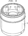
図7を参照すると、本発明に係る同軸キャビティアンテナ10の実施例の組み立て図が示されている。また、図8では、本発明の同軸キャビティアンテナの断面図が示されている。
【0021】
内部導体12と外部導体14の直径、及びケーブル支持部32、隔壁30、開口歯部24と連結されるアイリスリング26の使用についての計算が、以下に示すようになされる。上記したように、給電ケーブルが配設されてケーブル支持部32にアースされており、このケーブル支持部32は、アイリスリング26に延びる同軸ケーブルの芯線を備えている。対向する給電ケーブル間の径方向の距離及びケーブル支持部32の大きさ、ケーブル支持部32とアイリスリング26との間隔、アイリスリング26の直径及び厚さ、及び端部18とアイリスリング26との分離は、すべて同軸給電ケーブルからアンテナへ効果的に伝送するための役割を果たしている。この伝送は、インピーダンス整合および/または電圧定在波比(VSWR)に関して特徴がある。隔壁30と開口歯部24とは、更なる整合サポート(matching support)を与えているが、主としてE面とH面とを等化している。結局、キャビティの全体的な深さがアンテナのパターン性能(pattern performance)に影響を与えている。上述したように、アンテナは広い周波数域で効果的なインピーダンス整合を提供するものである。
【0022】
偏波ダイバーシティは、フィードネットワークを使用することにより達成される。フィードネットワーク310,320の一例を図6に示す。フィードネットワークの使用により2つの直交する直線偏波、或いは両方の向き(sense)の円偏波(右と左)が生ずる。図6に示すように、2つの180度ハイブリッド340はいずれかの場合に利用され、90度ハイブリッドは、2重円偏波を得るために、フィードネットワークに対するハイブリッドの後に追加される。特に、TE11同軸モードは、対向配置された同軸給電ターミナル330a,330bから給電信号によって励起(excite)され、同軸給電ターミナルは、等しい偏角と、180度ハイブリッド340に対して互いに180度の位相ずれを有する。180度ハイブリッドの出力それぞれは、直線偏波の1つの向き(sense)を与える。デルタポート(delta port)は、終了する。このように180度ハイブリッド340を使用すると、4つの同軸給電ターミナルからの信号が2つの直交する直線偏波に送信される。定義によれば、2つの直交する直線偏波が互いに90度でオフセットされている。アンテナの向きに依存して、これは垂直偏波及び水平偏波、2つの(±45度に向く)傾斜偏波(slant liner polarization)、若しくは他の組み合わせになる。
【0023】
続いて、90度ハイブリッドを通して、これらの出力に接続することで、90度ハイブリッド350の出力ポートで右及び左円偏波が生ずる。フィードネットワークが図1に示すような単一の同軸キャビティアンテナで使用された場合であっても、ネットワークは、図2及び図3と関連して以下に示すように、多重サブバンドを備えた同軸キャビティアンテナで作用するように修正される。この場合、フィードネットワークは、各サブバンドに複製される。
【0024】
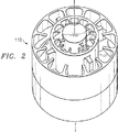
図2及び図3を参照すると、本発明の他の実施例を示すマルチバンド同軸キャビティアンテナ110,210が図示されている。上述したように、同軸キャビティアンテナの大きさは、図1に示すように、調整可能である。換言すると、異なる周波数帯域で使用できるように大きさを決めることができる。さらに、本発明に係る実施形態を示す同軸キャビティアンテナは、マルチバンドで動作するために入れ子にすることもできる。このように調整されて入れ子にされているものが、同軸キャビティアンテナ110,210として図示されている。同軸キャビティアンテナ110は、2つの同軸キャビティアンテナを備えている。小さく高周波数のアンテナが、大きく低周波数のアンテナの中に入れられている。同様に、同軸キャビティアンテナ210は、3つの同軸キャビティアンテナを備えている。本発明のアンテナは、図1,2,及び3に示すものに限定されるものではない。アンテナの数と大きさは、本発明のアンテナの形態を構成するように変更可能である。
【0025】
同軸キャビティアンテナ110,210に入れ子にされている各アンテナの構成要素は、図1に関連して示される同軸キャビティアンテナ10のそれと同様である。各構成要素は、大きさのみ相違している。したがって、図2及び図3のアンテナの構成については、再度記載をしない。複数のアンテナを入れ子にするために、アンテナの最も内側の外部導体が、その次に囲むアンテナの内部導体として作用する。これが連続するアンテナについて繰り返されている。さらに、入れ子にされている各アンテナは、(明確には図示しない)4つの同軸ケーブルと4つの同軸給電ターミナルとを別々に有している。このような同軸ケーブルは、同軸キャビティアンテナ10に関して上記したように、各アンテナに接続されている。
【0026】
図9を参照すると、低周波数或いは高周波数の電磁波を効果的に伝搬するアンテナを調整するための寸法が示されている。図9に示すアンテナの各部分は、アンテナの各部の詳細を示した図1と同様の符号で示されている。図9で示される各寸法を示す記載は、表1に示されている。
表1
寸法
R1− 外部キャビティの内半径
R2− 内部キャビティの外半径
R3− 給電プローブ芯線の外側部までの半径
R4− 給電プローブ芯線の中心までの半径
R5− 給電プローブシェルフ(probe shelf)までの半径
F− 給電リングの厚さ
G− 給電リングから給電プローブまでのギャップ幅
H− キャビティ基部から給電プローブまでの高さ
I− 給電プローブの上端から開口までの高さ
表1とともに図1及び図9を参照して、単一のサブバンド同軸キャビティアンテナの寸法が表2に示されている。
【0027】
【表2】

図1を参照すれば、示された寸法は、2.5GHZ〜4.50GHzの周波数域で作動するシングルサブバンド同軸キャビティアンテナのためのものである。この寸法は、図9に示され、表1に説明されている。
【0029】
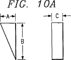
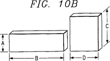
図10Aを参照すれば、図1及び図2の2重サブバンド同軸キャビティアンテナ110に示された12個の歯部24のうちの1つが図示されている。図10Bは、図1の同軸キャビティアンテナ10及び図2の2重サブバンド同軸キャビティアンテナ110に示された隔壁30の2つの部分を図示している。表3には、2.50GHZ〜4.50GHzの周波数域で作動する図1のシングルサブバンド同軸キャビティアンテナ10の歯部24の各々の寸法が与えられている。表4は、2.50GHZ〜4.50GHzの周波数域で作動する前記シングルサブバンドアンテナの隔壁30の2つの部分の寸法を与えている。他の周波数では、表2,3及び4に与えられた寸法は、要求に応じて調節される。
【0030】
【表3】
【表4】
表5,6及び7に、図2に示された2重サブバンド同軸キャビティアンテナ110の寸法が例として与えられている。表5,6及び7に与えられた寸法は、0.50GHz〜0.10GHzの周波数域で作動する低い方のサブバンドと、0.1GHz〜2.00GHzの周波数域で作動する高い方のサブバンドとを備える、0.50GHz〜2.00GHzの周波数域で作動する2重サブバンドアンテナのためのものである。図9,10A及び10Bと表1とに、表5,6及び7と図2の2重サブバンド同軸キャビティアンテナ110との寸法の関係を示すための参照記号が付されている。表6及び7に関し、これらの表の各々の寸法の最初の又は上方の一組は、0.50GHz〜1.00GHzの周波数域での下方のサブバンドのためのものであり、表6及び7の下方の寸法の一組は、1.00GHz〜2.00の帯域におけるサブバンドのためのものであることに気付く。これらの寸法は、表5,6及び7によって与えられた寸法の周波数域より高いか或いはより低い周波数域で作動するアンテナに対しては、その率に応じて定められる。
【0033】
【表5】
【表6】
【表7】
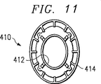
図11を参照すれば、整形され電磁波を伝搬させる本発明に係る同軸キャビティアンテナの一実施形態が示されている。図11の同軸キャビティアンテナ410は、楕円形に形成された内側導電体412と同じ楕円形に形成された外側導電体414とを有している。図11の整形された同軸キャビティアンテナ410は、図1に記載されたような環状に配置された隙間歯部と、(図1にも示されている)隙間ブロック又は隙間隔壁を有している。整形された同軸キャビティアンテナ410はまた、図5及び図7に示されたようなケーブル支持体32を有している。従って、図1のアンテナから図11のアンテナの変更は、楕円形の内側導電体412と同じ楕円形の外側導電体414にあることが分かる。
【0037】
図11に関し、図2及び図3に示されたような多重バンド同軸キャビティアンテナは、整形された電磁波を伝搬するために、楕円形の内側導電体及び外側導電体を有することができるということにも気付くべきである。
【0038】
図12を参照すれば、同軸キャビティアンテナを垂直アレイに組み込んだ本発明の一実施形態が示されている。図示のように、シングルサブバンド同軸キャビティアンテナ510は、シングルサブバンド同軸キャビティアンテナ512に対して垂直方向に配置されている。本発明に係るこれら同軸キャビティアンテナの垂直アレイは、ビーム幅を小さくすることによって、指向性(利得)を増加させることにある。図12は、2つのシングルサブバンドアンテナのみを図示しており、図1に関して垂直アレイを記載しているが、更に指向性を高めるために、垂直方向にアンテナを追加して配列しても良い。さらに、図2及び図3の多重バンド同軸キャビティアンテナを垂直方向に配列し、電磁波の伝搬に増幅された指向性を付与しよても良い。アンテナ510、512は、図1のアンテナに関して記述された種々の部分を含むことに気付くべきである。
【0039】
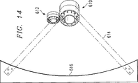
ここで図13及び図14を参照すれば、本発明に係る同軸キャビティアンテナのラインアレイ(直線配列)が図示されている。図13及び図14のアンテナは、反射フィード線として図示されているが、このことは例示であってこれに制限されるものではない。図示のように、このラインアレイは、受信同軸キャビティアンテナ610の水平ラインと送信同軸キャビティアンテナ612の水平ラインとを有している。アンテナ610と612のラインアレイは、支持体614上に搭載され、リフレクター616から離隔されている。
【0040】
同軸キャビティアンテナ610及び612は、図1に示されたようなシングルサブバンドアンテナ10を備えている。これらのアンテナは、その作動システムの周波数帯幅に応じて大きさを定められる。
【0041】
上述した本発明に係る種々のアンテナは、多くの応用を有している。これらの応用は、広帯域、可変周波数、高利得、及び偏波ダイバースのアンテナとしての使用を含む。この同軸アンテナは、正確な方向検知を遂行するためのインターフェロメトリーアレイの一要素として使用され得る。前記アンテナは、レーダー警告受信アンテナとしても使用され得る。この同軸アンテナの独特のパターン性能は、エミッター偏光を特徴づけるための極めて高い精度の偏向分析アンテナとして使用することも可能である。さらに、このアンテナの環状対称性は、実質的に等しい方位角と仰角パターン性能を付与する。
【0042】
幾つかの応用のために、長距離のプラットフォームのように、広い方位角と狭い仰角のパターン性能を有することが要望され得る。これは、アンテナの形状を、図11に示すように楕円又は矩形に変形することによって達成され得る。その長くした寸法は、ヴューカバー範囲をより狭くし、アンテナの指向性を増す。このことは、2つの同軸アンテナを垂直方向に積み重ねることによっても達成され得る。
【0043】
本発明の広帯域同軸アンテナは、個々のアンテナ要素としての使用に加えて、図13及び図14に示されたようなリフレクターアンテナのためのフィード体としても配列され寄与し得る。本発明の技術を組み込んだ複数の同軸アンテナは、広周波数域に亘り、且つほぼ頂点に中心をおいてヴュー範囲の最低120度に亘り、平坦な位相反応を示す。この反応は、平坦な振幅反応である。このことは、該アンテナが、超高速パルスの受信及び送信のための広帯域アンテナ及び極広帯域アンテナとして使用され得ることを許容する。本発明の同軸アンテナは、カセグレイン式、グレゴリー式、コーナー式、パラボラ式、或いは、円筒型のリフレクターとして使用される際に、全最大作動帯域に亘って高利得を示す。
【0044】
カセグレイン式及び円筒型のシングルリフレクターアンテナが、これまでに製造されている。ガセグレイン式リフレクターアンテナの作動帯域全般に亘る利得は、少なくとも最低30dBである。このリフレクターは、組み込まれたフィードネットワークを介して単偏極又は全偏極のために構成された同軸アンテナを使用する。フィードネットワークを備える結果として生じるリフレクターアンテナは、水平方向、垂直方向、右回り、及び左回りの4つの基本偏極を含む全偏極において受信し或いは送信する。
【0045】
本発明のアンテナは、如何なるタイプのリフレクターのためのフィード体としても有用である。しかしながら、円筒型のものについては、そのアンテナは、ラインフィードアレイに配置され、そのリフレクターの変化の無い平面で電子的に走査される。オフセットラインアレイは、最初に繋がれたラインアレイの隣に配置され、その結果、そのリフレクターアンテナは、同じ口径エリア内で作動する多重帯域全般に亘り有用なものとなる。
【0046】
本発明及びその利点を詳細に記述してきたが、請求の範囲に記載された本発明の精神及び範囲を逸脱しない限りにおいて、種々の交換、代替、及び変更がなされ得る。
【図面の簡単な説明】
【図1】 本発明の実施形態を示す同軸キャビティアンテナの等測図である。
【図2】 本発明の実施形態をさらに示すマルチバンド同軸キャビティアンテナの等測図である。
【図3】 本発明のさらに別の実施形態を示すマルチバンド同軸キャビティアンテナの等測図である。
【図4】 図1の同軸キャビティアンテナの内部の等測図である。
【図5】 図1の同軸キャビティアンテナの外部の等測図である。
【図6A】 本発明のアンテナとともに使用するためのアンテナフィードネットワークを示すダイヤグラムである。
【図6B】 本発明のアンテナとともに使用するためのアンテナフィードネットワークを示すダイヤグラムである。
【図7】 本発明の実施形態を示す同軸キャビティアンテナの分解図である。
【図8】 本発明による同軸キャビティアンテナの断面図である。
【図9A】 アンテナの寸法を確認する、本発明による同軸キャビティアンテナの概略図である。
【図9B】 アンテナの寸法を確認する、本発明による同軸キャビティアンテナの概略図である。
【図10A】 前出の図の同軸キャビティアンテナ用の開口歯の概略図である。
【図10B】 前出の図の同軸キャビティアンテナ用の虹彩環状隔壁の概略図である。
【図11】 本発明の実施形態を示す、円以外のパターンを放射するための同軸キャビティアンテナの等測図である。
【図12】 図1から図3の実施形態により示された垂直に配置された同軸キャビティアンテナの等測図である。
【図13】 図1から図3の実施形態により示された直線に配置された同軸キャビティアンテナの等測図である。
【図14】(Technical field to which the invention belongs)
The present invention relates generally to antennas, and more particularly to coaxial cavity antennas.
[0001]
(Background of the Invention)
Coaxial antennas have been manufactured for quite some time. However, a major drawback was the difference between the electric field plane (“E-plane”) and magnetic field plane (“H-plane”) patterns. In particular, in a typical coaxial radiator, the E-plane pattern narrows as the frequency increases due to the difference in the E-plane and H-plane aperture distributions. Such narrowing is undesirable in a dual polarization antenna. That is, the final result is that, as one meaning of polarization, the elevation angle becomes narrower when the angle is widened, and as the other meaning of polarization, the elevation angle becomes wider when the angle is narrowed. For the case of dual circularly polarized coaxial antennas, this is undesirable because it results in unacceptable axial ratio performance. Similarly, for a dual linearly polarized coaxial antenna, the difference between the E-plane and H-plane patterns is an unacceptable difference in the view cover range. The difference in E-plane and H-plane patterns further limits the useful working bandwidth.
[0002]
Previous coaxial antenna technology has an available bandwidth of approximately 30%. This is achieved by various combinations of inner to outer diameter conductors, radial aperture stubs, and various other feed mechanisms and arrangements.
[0003]
(Summary of Invention)
Therefore, there has been a growing demand for antennas with various polarizations, high gains, wide bandwidths and low dispersion characteristics. The present invention provides a coaxial cavity antenna that addresses the shortcomings of prior systems and methods.
[0004]
According to one embodiment of the present invention, a coaxial cavity antenna includes a generally cylindrical inner conductor that is sized to propagate electromagnetic signals in a desired frequency band. The coaxial antenna further includes a substantially cylindrical outer conductor that is formed substantially coaxial with the inner conductor and has a larger diameter than the inner conductor. The outer conductor includes an open ring disposed at the end of the outer conductor. The outer conductor is disposed with respect to the inner conductor so as to form a cavity portion between the inner conductor and the outer conductor. The cavity is sized to propagate an electromagnetic signal in a desired frequency band. The coaxial cavity antenna further includes a plurality of aperture teeth disposed in the vicinity of the aperture ring, and an iris ring disposed in the cavity portion at a desired distance from the aperture ring. The coaxial cavity antenna further includes a plurality of partitions connected to the inner conductor and the iris ring, and a plurality of cable supports connected to the outer conductor.
[0005]
The present invention provides a number of technical advantages. For example, the problem of narrow E-plane is minimized in the antenna according to the invention. The antenna of the present invention has a substantially symmetrical E-plane and H- for an appropriate wide angle, such as ± 60 °, and an appropriate wide frequency bandwidth, such as one octave per subband. Indicates the performance of the surface. Another advantage of the present invention is that the antenna is coaxial so as to provide multi-octave performance by appropriately selecting the antenna's range and the size and depth of the cavity from inside to outside. It is a point that can be nested in the nest.
[0006]
Other advantages provided by the present invention include: dual polarization, high gain, relatively small size and light weight, wide bandwidth, with respect to pattern control, phase and amplitude tracking, and cross polarization. Excellent response in amplitude and phase. All of these exceed the view range of ± 60 ° or more. Antennas according to the present invention have been configured with bandwidths of 0.5 to 2.0 GHz, 2.0 to 8.0 GHz, and 2.0 to 18.0 GHz as a whole.
[0007]
The antenna according to the invention has application methods as elements of interferometers, polarization antennas and as elements when various types of reflectors feed. Antennas embodying the invention have dispersion characteristics that make them excellent time domain antennas for use in very wide band systems. The antennas according to the present invention can be arranged vertically stacked so as to increase directivity (gain) by narrowing the elevation beam width. Furthermore, the antenna according to the invention has been found to be relatively simple and repeatable to machine and assemble because there are very few machine parts.
[0008]
In summary, the present invention provides a novel, wide-band, high-gain antenna that can simultaneously generate double linearly polarized waves and double circularly polarized waves. The desired symmetrical E-plane and H-plane patterns for wide bandwidth previously unknown in coaxial antennas have been achieved by the physical synthesis of the present invention.
[0009]
Other technical advantages will be readily apparent to one skilled in the art from the following figures, descriptions, and claims.
[0010]
(Preferred embodiment)
The embodiments of the antenna and the advantages of the antenna according to the present invention are best understood by referring to FIGS. 1 to 13 of the drawings, and like numerals are used for like corresponding parts in the various figures. ing.
[0011]
FIG. 1 is a diagram of a
[0012]
For a more complete understanding of the present invention and its advantages, reference is now made to the following description taken in conjunction with the accompanying drawings.
[0013]
The
[0014]
As shown in the figure, the
[0015]
The
[0016]
The
[0017]
Further, the
[0018]
All components shown as above are preferably composed of conductive members. Aluminum is fairly lightweight and inexpensive. However, when used for items that are susceptible to weight,Conductive composite materialCan be used.
[0019]
As shown in FIG. 5, a plurality of
[0020]
Referring to FIG. 7, an assembly diagram of an embodiment of a
[0021]
Calculations regarding the diameter of the
[0022]
Polarization diversity is achieved by using a feed network. An example of the
[0023]
Subsequently, by connecting to these outputs through a 90-degree hybrid, right and left circularly polarized waves are generated at the output port of the 90-
[0024]
2 and 3, multi-band
[0025]
The components of each antenna nested within the
[0026]
Referring to FIG. 9, there are shown dimensions for adjusting an antenna that effectively propagates low or high frequency electromagnetic waves. Each part of the antenna shown in FIG. 9 is denoted by the same reference numerals as those in FIG. 1 showing details of each part of the antenna. A description showing each dimension shown in FIG. 9 is shown in Table 1.
Table 1
Size
R1- Inner radius of external cavity
R2- Outer radius of inner cavity
R3- Radius to the outside of the feed probe core wire
R4- Radius to the center of the feed probe core wire
R5- Radius to the probe shelf
F- thickness of feed ring
G- Gap width from feed ring to feed probe
H- Height from the cavity base to the feed probe
I- Height from the top of the feed probe to the opening
Referring to FIGS. 1 and 9 together with Table 1, the dimensions of a single subband coaxial cavity antenna are shown in Table 2.
[0027]
[Table 2]
Referring to FIG. 1, the dimensions shown are for a single subband coaxial cavity antenna operating in the frequency range of 2.5 GHz to 4.50 GHz. This dimension is shown in FIG. 9 and described in Table 1.
[0029]
Referring to FIG. 10A, one of the twelve
[0030]
[Table 3]
[Table 4]
In Tables 5, 6 and 7, the dimensions of the dual subband
[0033]
[Table 5]
[Table 6]
[Table 7]
Referring to FIG. 11, an embodiment of a coaxial cavity antenna according to the present invention that is shaped and propagates electromagnetic waves is shown. A
[0037]
With respect to FIG. 11, a multi-band coaxial cavity antenna as shown in FIGS. 2 and 3 can have elliptical inner and outer conductors to propagate shaped electromagnetic waves. You should also notice.
[0038]
Referring to FIG. 12, one embodiment of the present invention incorporating a coaxial cavity antenna in a vertical array is shown. As illustrated, the single subband
[0039]
Referring now to FIGS. 13 and 14, a line array (linear array) of coaxial cavity antennas according to the present invention is illustrated. Although the antennas of FIGS. 13 and 14 are illustrated as reflective feed lines, this is exemplary and not limiting. As shown, this line array has a horizontal line for the receive
[0040]
The
[0041]
The various antennas according to the present invention described above have many applications. These applications include the use as wideband, variable frequency, high gain, and polarization diversity antennas. This coaxial antenna can be used as an element of an interferometry array to perform accurate direction sensing. The antenna can also be used as a radar warning receiving antenna. The unique pattern performance of this coaxial antenna can also be used as an extremely accurate deflection analysis antenna to characterize emitter polarization. Further, the annular symmetry of this antenna provides substantially equal azimuth and elevation pattern performance.
[0042]
For some applications, it may be desired to have wide azimuth and narrow elevation pattern performance, such as a long distance platform. This can be achieved by transforming the shape of the antenna into an ellipse or rectangle as shown in FIG. The longer dimensions make the view cover range narrower and increase the antenna directivity. This can also be achieved by stacking two coaxial antennas vertically.
[0043]
In addition to use as individual antenna elements, the broadband coaxial antenna of the present invention can also be arranged and contributed as a feed for a reflector antenna as shown in FIGS. Multiple coaxial antennas incorporating the technology of the present invention exhibit a flat phase response over a wide frequency range and approximately centered at the apex and over a minimum of 120 degrees in the view range. This response is a flat amplitude response. This allows the antenna to be used as a broadband antenna and an ultra-wideband antenna for receiving and transmitting ultrafast pulses. The coaxial antenna of the present invention exhibits a high gain over the entire maximum operating band when used as a Cassegrain, Gregory, corner, parabolic, or cylindrical reflector.
[0044]
Case-grain and cylindrical single reflector antennas have been manufactured so far. The gain over the entire operating band of the gassegrain reflector antenna is at least 30 dB. This reflector uses a coaxial antenna configured for unipolar or full polarization through an integrated feed network. The resulting reflector antenna with a feed network receives or transmits in all polarizations, including the four basic polarizations in the horizontal, vertical, clockwise and counterclockwise directions.
[0045]
The antenna of the present invention is useful as a feed body for any type of reflector. However, for cylindrical ones, the antenna is placed in a line feed array and electronically scanned in a plane without change in the reflector. The offset line array is placed next to the first connected line array so that the reflector antenna is useful across multiple bands operating in the same aperture area.
[0046]
Although the invention and its advantages have been described in detail, various changes, substitutions, and alterations may be made without departing from the spirit and scope of the invention as set forth in the claims.
[Brief description of the drawings]
FIG. 1 is an isometric view of a coaxial cavity antenna showing an embodiment of the present invention.
FIG. 2 is an isometric view of a multiband coaxial cavity antenna further illustrating an embodiment of the present invention.
FIG. 3 is an isometric view of a multiband coaxial cavity antenna showing yet another embodiment of the present invention.
FIG. 4 is an isometric view of the inside of the coaxial cavity antenna of FIG.
FIG. 5 is an isometric view of the outside of the coaxial cavity antenna of FIG. 1;
6A is a diagram showing an antenna feed network for use with the antenna of the present invention. FIG.
FIG. 6B is a diagram illustrating an antenna feed network for use with the antenna of the present invention.
FIG. 7 is an exploded view of a coaxial cavity antenna showing an embodiment of the present invention.
FIG. 8 is a cross-sectional view of a coaxial cavity antenna according to the present invention.
FIG. 9A is a schematic view of a coaxial cavity antenna according to the present invention, confirming the dimensions of the antenna.
FIG. 9B is a schematic view of a coaxial cavity antenna according to the present invention, confirming the dimensions of the antenna.
FIG. 10A is a schematic diagram of an aperture tooth for the coaxial cavity antenna of the previous figure.
FIG. 10B is a schematic diagram of an iris ring bulkhead for the coaxial cavity antenna of the previous figure.
FIG. 11 is an isometric view of a coaxial cavity antenna for radiating a pattern other than a circle, illustrating an embodiment of the present invention.
12 is an isometric view of a vertically arranged coaxial cavity antenna shown by the embodiment of FIGS. 1-3. FIG.
13 is an isometric view of a coaxial cavity antenna arranged in a straight line illustrated by the embodiment of FIGS. 1-3. FIG.
FIG. 14
Claims (37)
前記内部導体と同軸に配置された少なくとも1つの円筒状の外部導体であって、連続する各外部導体は隣接した外部導体よりも大きな直径を有しており、その一部として開口リングを有し、少なくとも1つの外部導体の1つが前記内部導体に対して前記内部導体及び隣接した外部導体間にキャビティを形成するように配置されており、外部導体の連続する各ペアがキャビティを形成するように配置されており、各キャビティが予め選択された周波数帯域において電磁信号の伝播を行うための大きさとされた外部導体と、
径方向に向けられて各開口リングの周囲に配置された複数の開口歯部と、
前記内部導体及び前記外部導体間の前記各キャビティの内部に配置されるアイリスリングであって、前記内部導体に取り付けられ、前記内部導体に給電し、前記各キャビティ内にアイリスリングを含む前記外部導体の連続する各ペアは、前記外部導体の連続するペアの内側の1つに取り付けられ、前記外部導体の連続するペアの内側の1つに給電するアイリスリングと、
各アイリスリングに結合された複数の隔壁とを備える同軸キャビティアンテナ。A cylindrical inner conductor for propagation of electromagnetic signals in a preselected frequency band;
At least one cylindrical outer conductor disposed coaxially with the inner conductor, each successive outer conductor having a larger diameter than an adjacent outer conductor, and having an opening ring as a part thereof , At least one of the outer conductors is disposed with respect to the inner conductor to form a cavity between the inner conductor and an adjacent outer conductor, such that each successive pair of outer conductors forms a cavity. An outer conductor, wherein each cavity is sized for propagation of electromagnetic signals in a preselected frequency band;
A plurality of aperture teeth arranged radially around each aperture ring;
An iris ring disposed in each cavity between the inner conductor and the outer conductor, the outer conductor being attached to the inner conductor, supplying power to the inner conductor, and including an iris ring in each cavity Each successive pair of is attached to one inside the successive pair of outer conductors, and an iris ring that feeds one inside the successive pair of outer conductors ;
A coaxial cavity antenna comprising a plurality of bulkheads coupled to each iris ring.
前記内部導体と同軸に配置された円筒状の外部導体であって、前記内部導体よりも大きな直径を有しており、前記外部導体はその一部として開口リングを有し、前記外部導体が前記内部導体に対して前記内部導体及び外部導体間にキャビティを形成するように配置されており、前記キャビティが予め選択された周波数帯域において電磁信号の伝播を行うための大きさとされた外部導体と、
径方向に向けられて前記開口リングの周囲に配置された複数の開口歯部と、
前記キャビティの内部に配置されたアイリスリングであって、前記内部導体に取り付けられ、前記内部導体に給電するアイリスリングと、
前記内部導体及び前記アイリスリングに結合された複数の隔壁とを備える同軸キャビティアンテナ。A cylindrical inner conductor sized for propagation of electromagnetic signals in a preselected frequency band;
A cylindrical outer conductor disposed coaxially with the inner conductor, having a larger diameter than the inner conductor, the outer conductor having an opening ring as a part thereof, and the outer conductor being An outer conductor arranged to form a cavity between the inner conductor and the outer conductor with respect to the inner conductor, wherein the cavity is sized for propagation of electromagnetic signals in a preselected frequency band;
A plurality of openings teeth disposed around the opening ring radially directed,
An iris ring disposed inside the cavity, the iris ring being attached to the inner conductor and supplying power to the inner conductor ;
A coaxial cavity antenna comprising a plurality of partition walls coupled to the inner conductor and the iris ring.
前記内部導体を取り囲み、前記内部導体と略同軸に配置された第一及び第二外部導体であって、前記第二外部導体は隣接した前記第一外部導体よりも大きな直径を有しており、前記第一外部導体が前記内部導体に対して前記内部導体及び前記第一外部導体間にキャビティを形成するように配置されており、前記第二外部導体が前記第一外部導体及び前記第二外部導体間にキャビティを形成するように配置されており、各キャビティが予め選択された前記周波数帯域において電磁信号の伝播を行うための大きさとされた外部導体と、
複数のアイリスリングであって、各アイリスリングはキャビティの内部に配置され、隣接した導体とキャビティを形成する導体の外部面と接触するための大きさとされ、更に、隣接した導体の内部面と接触しない大きさとされ、前記外部面に接触する各導体に給電するアイリスリングとを備える同軸キャビティアンテナ。An inner conductor sized for propagation of electromagnetic signals in a preselected frequency band;
First and second outer conductors surrounding the inner conductor and disposed substantially coaxially with the inner conductor, the second outer conductor having a larger diameter than the adjacent first outer conductor; The first outer conductor is disposed so as to form a cavity between the inner conductor and the first outer conductor with respect to the inner conductor, and the second outer conductor is the first outer conductor and the second outer conductor. An outer conductor arranged to form cavities between the conductors, each cavity being sized for propagation of electromagnetic signals in the preselected frequency band;
A plurality of iris rings, each iris ring being disposed within the cavity, sized to contact an adjacent conductor and an outer surface of the conductor forming the cavity, and further contact the inner surface of the adjacent conductor A coaxial cavity antenna comprising an iris ring that is sized so as not to be fed and that feeds each conductor in contact with the outer surface .
前記内部導体と同軸に配置された第一外部導体であって、前記第一外部導体は前記内部導体に対して前記内部導体及び前記第一外部導体間に第一キャビティを形成するように配置されており、前記第一キャビティが予め選択された前記周波数帯域において電磁信号の伝播を行うための大きさとされた第一外部導体と、
前記第一外部導体と同軸に配置された第二外部導体であって、前記第二外部導体は前記第一外部導体よりも大きな直径を有しておりその一部として開口リングを有し、前記第二外部導体が前記第一外部導体に対して前記第二外部導体及び前記第一外部導体間に第二キャビティを形成するように配置されており、前記第二キャビティが予め選択された周波数帯域において電磁信号の伝播を行うための大きさとされた第二の外部導体と、
径方向に向けられて前記第二外部導体の開口リングの周囲に配置された複数の開口歯部と、
前記第一キャビティの内部に配置された第一アイリスリングであって、前記内部導体に取り付けられ、前記内部導体に給電する第一アイリスリングと、
前記第二キャビティの内部に配置された第二アイリスリングであって、前記第一外部導体に取り付けられ、前記第一外部導体に給電する第二アイリスリングと、
前記第二アイリスリングに結合された複数の隔壁とを備える同軸キャビティアンテナ。An inner conductor sized for propagation of electromagnetic signals in a preselected frequency band;
A first outer conductor disposed coaxially with the inner conductor, wherein the first outer conductor is disposed so as to form a first cavity between the inner conductor and the first outer conductor with respect to the inner conductor. A first outer conductor sized for propagation of electromagnetic signals in the frequency band preselected for the first cavity;
A second outer conductor disposed coaxially with the first outer conductor, wherein the second outer conductor has a larger diameter than the first outer conductor and has an opening ring as a part thereof, A second outer conductor is disposed with respect to the first outer conductor to form a second cavity between the second outer conductor and the first outer conductor, and the second cavity is a preselected frequency band. A second outer conductor sized for propagation of electromagnetic signals at
A plurality of opening teeth arranged radially around the opening ring of the second outer conductor;
A first iris ring disposed within the first cavity, the first iris ring being attached to the inner conductor and supplying power to the inner conductor ;
A second iris ring disposed within the second cavity, the second iris ring being attached to the first outer conductor and supplying power to the first outer conductor ;
A coaxial cavity antenna comprising a plurality of partition walls coupled to the second iris ring.
前記内部導体と同軸に配置された外部導体であって、前記内部導体よりも大きな直径を有し、その一部として該外部導体の一端部に開口リングを有し、前記内部導体に対して前記内部導体及び外部導体間にキャビティを形成するように配置されており、前記キャビティが予め選択された周波数帯域において電磁信号の伝播を行うための大きさとされた外部導体と、
径方向に向けられて前記開口リングの周囲に配置された複数の開口歯部と、
前記キャビティの内部に配置されたアイリスリングであって、前記内部導体に取り付けられ、前記内部導体に給電するアイリスリングと、
前記内部導体及びアイリスリングに結合された複数の隔壁とを備える同軸キャビティアンテナ。An inner conductor sized to propagate electromagnetic signals in a preselected frequency band;
An outer conductor disposed coaxially with the inner conductor, having a larger diameter than the inner conductor, and having an opening ring at one end of the outer conductor as part of the outer conductor; An outer conductor disposed to form a cavity between the inner conductor and the outer conductor, the cavity being sized for propagation of electromagnetic signals in a preselected frequency band;
A plurality of aperture teeth arranged radially around the aperture ring;
An iris ring disposed inside the cavity, the iris ring being attached to the inner conductor and supplying power to the inner conductor ;
A coaxial cavity antenna comprising a plurality of partition walls coupled to the inner conductor and an iris ring.
少なくとも1つの付加的な同軸キャビティアンテナであって、各々が予め決められた周波数帯域の電磁信号の伝播のためのサイズとされ、各々前記第一の同軸キャビティアンテナの長手方向軸線と一致した長手方向軸線を有する同軸キャビティアンテナとを備えた縦スタック型同軸キャビティアンテナアレーであって、
該縦型アレーの各同軸キャビティアンテナは、
予め選択された周波数帯域において電磁信号の伝播を行うようにサイズ決めされた内部導体と、
前記内部導体と同軸に配置された外部導体であって、前記内部導体よりも大きな直径を有し、その一部として該外部導体の一端部に開口リングを有し、前記内部導体に対して前記内部導体及び外部導体間にキャビティを形成するように配置されており、前記キャビティが予め選択された周波数帯域において電磁信号の伝播を行うための大きさとされた外部導体と、
径方向に向けられて前記開口リングの周囲に配置された複数の開口歯部と、
前記キャビティの内部に配置されたアイリスリングであって、前記内部導体に取り付けられ、前記内部導体に給電するアイリスリングと、
前記内部導体及びアイリスリングに結合された複数の隔壁とを備える縦スタック型同軸キャビティアンテナ。A first coaxial cavity antenna having a longitudinal axis and sized for propagation of electromagnetic signals in a predetermined frequency band;
At least one additional coaxial cavity antenna, each sized for propagation of electromagnetic signals in a predetermined frequency band, each longitudinally coincident with the longitudinal axis of said first coaxial cavity antenna A vertically stacked coaxial cavity antenna array having a coaxial cavity antenna having an axis,
Each coaxial cavity antenna of the vertical array is
An inner conductor sized to propagate electromagnetic signals in a preselected frequency band;
An outer conductor disposed coaxially with the inner conductor, having a larger diameter than the inner conductor, and having an opening ring at one end of the outer conductor as part of the outer conductor; An outer conductor disposed to form a cavity between the inner conductor and the outer conductor, the cavity being sized for propagation of electromagnetic signals in a preselected frequency band;
A plurality of aperture teeth arranged radially around the aperture ring;
An iris ring disposed inside the cavity, the iris ring being attached to the inner conductor and supplying power to the inner conductor ;
A vertically stacked coaxial cavity antenna comprising a plurality of partition walls coupled to the inner conductor and an iris ring.
少なくとも1つの付加的な同軸キャビティアンテナであって、予め決められた周波数帯域の電磁信号の伝播のためのサイズとされ、各々隣り合う同軸キャビティアンテナの長手方向軸線と平行な長手方向軸線を有する同軸キャビティアンテナとを備えた同軸キャビティアンテナアレーであって、
前記第一の同軸キャビティアンテナと前記少なくとも1つの付加的な同軸キャビティアンテナとは、
予め選択された周波数帯域において電磁信号の伝播を行うようにサイズ決めされた内部導体と、
前記内部導体と同軸に配置された外部導体であって、前記内部導体よりも大きな直径を有し、その一部として該外部導体の一端部に開口リングを有し、前記内部導体に対して前記内部導体及び外部導体間にキャビティを形成するように配置されており、前記キャビティが予め選択された周波数帯域において電磁信号の伝播を行うための大きさとされた外部導体と、
径方向に向けられて前記開口リングの周囲に配置された複数の開口歯部と、
前記キャビティの内部に配置されたアイリスリングであって、前記内部導体に取り付けられ、前記内部導体に給電するアイリスリングと、
前記内部導体及びアイリスリングに結合された複数の隔壁とを備える同軸キャビティアンテナ。A first coaxial cavity antenna having a longitudinal axis and sized for propagation of electromagnetic signals in a predetermined frequency band;
At least one additional coaxial cavity antenna, sized for propagation of electromagnetic signals in a predetermined frequency band, each having a longitudinal axis parallel to a longitudinal axis of an adjacent coaxial cavity antenna A coaxial cavity antenna array with a cavity antenna,
The first coaxial cavity antenna and the at least one additional coaxial cavity antenna are:
An inner conductor sized to propagate electromagnetic signals in a preselected frequency band;
An outer conductor disposed coaxially with the inner conductor, having a larger diameter than the inner conductor, and having an opening ring at one end of the outer conductor as part of the outer conductor; An outer conductor disposed to form a cavity between the inner conductor and the outer conductor, the cavity being sized for propagation of electromagnetic signals in a preselected frequency band;
A plurality of aperture teeth arranged radially around the aperture ring;
An iris ring disposed inside the cavity, the iris ring being attached to the inner conductor and supplying power to the inner conductor ;
A coaxial cavity antenna comprising a plurality of partition walls coupled to the inner conductor and an iris ring.
予め選択された周波数帯域において電磁信号の伝播を行うようにサイズ決めされた円筒状の内部導体と、
前記内部導体と同軸に配置された円筒状の外部導体であって、前記内部導体よりも大きな直径を有し、その一部として開口リングを有し、前記内部導体に対して前記内部導体及び外部導体間にキャビティを形成するように配置されており、前記キャビティが予め選択された周波数帯域において電磁信号の伝播を行うための大きさとされた外部導体と、
径方向に向けられて前記開口リングの周囲に配置された複数の開口歯部と、
前記キャビティの内部に配置されたアイリスリングであって、前記円筒状の内部導体に取り付けられ、前記円筒状の内部導体に給電するアイリスリングと、
前記内部導体及び前記アイリスリングに結合された複数の隔壁と、
前記アイリスリングに接続された複数の同軸ケーブルと、
アンテナフィードネットワークと
を備えており、
該アンテナフィードネットワークは、
垂直直線偏波信号を発生する第一の180°ハイブリッドと、
水平直線偏波信号を発生する第二の180°ハイブリッドと、
前記第一の180°ハイブリッドからの前記垂直直線偏波信号及び前記第二の180°ハイブリッドからの前記水平直線偏波信号を受け取る90°ハイブリッドとを備え、該90°ハイブリッドは、複数の前記同軸ケーブルから選ばれたものに接続される左円偏波信号を発生し、複数の前記同軸ケーブルから選ばれた他のものに適用される右円偏波信号を発生するようにされている同軸キャビティアンテナシステム。A coaxial cavity antenna system comprising a coaxial cavity antenna, the coaxial cavity antenna comprising:
A cylindrical inner conductor sized to propagate electromagnetic signals in a preselected frequency band;
A cylindrical outer conductor disposed coaxially with the inner conductor, having a larger diameter than the inner conductor, having an opening ring as a part thereof, the inner conductor and the outer with respect to the inner conductor An outer conductor arranged to form a cavity between the conductors, the cavity being sized for propagation of electromagnetic signals in a preselected frequency band;
A plurality of aperture teeth arranged radially around the aperture ring;
An iris ring disposed within the cavity, the iris ring being attached to the cylindrical inner conductor and supplying power to the cylindrical inner conductor ;
A plurality of partition walls coupled to the inner conductor and the iris ring;
A plurality of coaxial cables connected to the iris ring;
With an antenna feed network and
The antenna feed network is
A first 180 ° hybrid that generates a vertically linearly polarized signal;
A second 180 ° hybrid that generates a horizontal linearly polarized signal;
A 90 ° hybrid that receives the vertical linearly polarized signal from the first 180 ° hybrid and the horizontal linearly polarized signal from the second 180 ° hybrid, the 90 ° hybrid comprising a plurality of the coaxials A coaxial cavity adapted to generate a left circularly polarized signal connected to a selected one of the cables and a right circularly polarized signal applied to another selected from the plurality of coaxial cables Antenna system.
予め選択された周波数帯域において電磁信号の伝播を行うようにサイズ決めされた円筒状の内部導体と、
前記内部導体と同軸に配置された円筒状の外部導体であって、前記内部導体よりも大きな直径を有し、その一部として開口リングを有し、前記内部導体に対して前記内部導体及び外部導体間にキャビティを形成するように配置されており、前記キャビティが予め選択された周波数帯域において電磁信号の伝播を行うための大きさとされた外部導体と、
径方向に向けられて前記開口リングの周囲に配置された複数の開口歯部と、
前記キャビティの内部に配置されたアイリスリングであって、前記円筒状の内部導体に取り付けられ、前記円筒状の内部導体に給電するアイリスリングと、
前記内部導体及び前記アイリスリングに結合された複数の隔壁と、
前記アイリスリングに接続された複数の同軸ケーブルと、
アンテナフィードネットワークと
を備えており、
該アンテナフィードネットワークは、
複数の前記同軸ケーブルから選ばれたものに適用される垂直直線偏波信号を発生する第一の180°ハイブリッドと、
複数の前記同軸ケーブルから選ばれた他のものに適用される水平直線偏波信号を発生する第二の180°ハイブリッドとを備えている同軸キャビティアンテナシステム。A coaxial cavity antenna system comprising a coaxial cavity antenna, the coaxial cavity antenna comprising:
A cylindrical inner conductor sized to propagate electromagnetic signals in a preselected frequency band;
A cylindrical outer conductor disposed coaxially with the inner conductor, having a larger diameter than the inner conductor, having an opening ring as a part thereof, the inner conductor and the outer with respect to the inner conductor An outer conductor arranged to form a cavity between the conductors, the cavity being sized for propagation of electromagnetic signals in a preselected frequency band;
A plurality of aperture teeth arranged radially around the aperture ring;
An iris ring disposed within the cavity, the iris ring being attached to the cylindrical inner conductor and supplying power to the cylindrical inner conductor ;
A plurality of partition walls coupled to the inner conductor and the iris ring;
A plurality of coaxial cables connected to the iris ring;
With an antenna feed network and
The antenna feed network is
A first 180 ° hybrid that generates a vertically linearly polarized signal applied to a selection of a plurality of said coaxial cables;
A coaxial cavity antenna system comprising a second 180 ° hybrid for generating a horizontal linearly polarized signal applied to another selected from a plurality of said coaxial cables.
Applications Claiming Priority (3)
| Application Number | Priority Date | Filing Date | Title |
|---|---|---|---|
| US10496898P | 1998-10-20 | 1998-10-20 | |
| US60/104,968 | 1998-10-20 | ||
| PCT/US1999/024184 WO2000024084A1 (en) | 1998-10-20 | 1999-10-15 | Coaxial cavity antenna |
Publications (3)
| Publication Number | Publication Date |
|---|---|
| JP2002528936A JP2002528936A (en) | 2002-09-03 |
| JP2002528936A5 JP2002528936A5 (en) | 2009-07-02 |
| JP4428864B2 true JP4428864B2 (en) | 2010-03-10 |
Family
ID=22303410
Family Applications (1)
| Application Number | Title | Priority Date | Filing Date |
|---|---|---|---|
| JP2000577734A Expired - Fee Related JP4428864B2 (en) | 1998-10-20 | 1999-10-15 | Coaxial cavity antenna |
Country Status (7)
| Country | Link |
|---|---|
| US (1) | US6356241B1 (en) |
| EP (1) | EP1127383A1 (en) |
| JP (1) | JP4428864B2 (en) |
| CN (1) | CN1211884C (en) |
| AU (1) | AU1207800A (en) |
| CA (1) | CA2347013C (en) |
| WO (1) | WO2000024084A1 (en) |
Families Citing this family (22)
| Publication number | Priority date | Publication date | Assignee | Title |
|---|---|---|---|---|
| JP3706522B2 (en) * | 2000-02-25 | 2005-10-12 | シャープ株式会社 | Waveguide device for satellite receiving converter |
| US6577283B2 (en) * | 2001-04-16 | 2003-06-10 | Northrop Grumman Corporation | Dual frequency coaxial feed with suppressed sidelobes and equal beamwidths |
| US6831613B1 (en) * | 2003-06-20 | 2004-12-14 | Harris Corporation | Multi-band ring focus antenna system |
| US7053820B2 (en) * | 2004-05-05 | 2006-05-30 | Raytheon Company | Generating three-dimensional images using impulsive radio frequency signals |
| US20080094298A1 (en) * | 2006-10-23 | 2008-04-24 | Harris Corporation | Antenna with Shaped Asymmetric Main Reflector and Subreflector with Asymmetric Waveguide Feed |
| TWI449445B (en) * | 2010-10-07 | 2014-08-11 | Wistron Neweb Corp | Beamwidth adjustment device |
| CN102104191B (en) * | 2010-11-16 | 2013-08-07 | 浙江大学 | Homocentric ring antenna array based on realization of central concave directional diagram |
| US9166290B2 (en) | 2011-12-21 | 2015-10-20 | Sony Corporation | Dual-polarized optically controlled microwave antenna |
| US9716322B2 (en) | 2012-08-02 | 2017-07-25 | Raytheon Company | Multi-polarization antenna array for signal detection and AOA |
| US10027030B2 (en) | 2013-12-11 | 2018-07-17 | Nuvotronics, Inc | Dielectric-free metal-only dipole-coupled broadband radiating array aperture with wide field of view |
| JP6327928B2 (en) * | 2014-04-30 | 2018-05-23 | 三菱電機株式会社 | Primary radiator and multi-frequency antenna |
| CN105223539B (en) * | 2015-10-23 | 2018-04-13 | 成都九华圆通科技发展有限公司 | One kind lift-off interferometer direction finding system |
| US10431896B2 (en) | 2015-12-16 | 2019-10-01 | Cubic Corporation | Multiband antenna with phase-center co-allocated feed |
| US10170823B2 (en) * | 2016-04-27 | 2019-01-01 | Topcon Positioning Systems, Inc. | Embedded antenna device for GNSS applications |
| KR101842433B1 (en) * | 2016-09-01 | 2018-03-28 | 현대자동차주식회사 | Antenna and vehicle including the same |
| GB2578388A (en) | 2017-06-20 | 2020-05-06 | Cubic Corp | Broadband antenna array |
| US20190186369A1 (en) | 2017-12-20 | 2019-06-20 | Plasma Igniter, LLC | Jet Engine with Plasma-assisted Combustion |
| WO2019209461A1 (en) | 2018-04-25 | 2019-10-31 | Nuvotronics, Inc. | Microwave/millimeter-wave waveguide to circuit board connector |
| US11367948B2 (en) | 2019-09-09 | 2022-06-21 | Cubic Corporation | Multi-element antenna conformed to a conical surface |
| US11152710B2 (en) * | 2019-11-07 | 2021-10-19 | The Boeing Company | Wide-band conformal coaxial antenna |
| WO2022094325A1 (en) * | 2020-10-29 | 2022-05-05 | Optisys, Inc. | Integrated balanced radiating elements |
| US11936112B1 (en) * | 2022-05-05 | 2024-03-19 | Lockheed Martin Corporation | Aperture antenna structures with concurrent transmit and receive |
Family Cites Families (13)
| Publication number | Priority date | Publication date | Assignee | Title |
|---|---|---|---|---|
| GB1090790A (en) * | 1966-05-27 | 1967-11-15 | Standard Telephones Cables Ltd | Waveguide junction |
| DE2259082A1 (en) * | 1972-12-02 | 1974-06-06 | Messerschmitt Boelkow Blohm | WIDE-BAND, VERTICALLY POLARIZED ROUND-BEAM ANTENNA |
| US4042935A (en) * | 1974-08-01 | 1977-08-16 | Hughes Aircraft Company | Wideband multiplexing antenna feed employing cavity backed wing dipoles |
| US4443804A (en) | 1981-09-28 | 1984-04-17 | Ford Aerospace & Communications Corporation | Modified difference mode coaxial antenna with flared aperture |
| US5041840A (en) | 1987-04-13 | 1991-08-20 | Frank Cipolla | Multiple frequency antenna feed |
| US4903037A (en) | 1987-10-02 | 1990-02-20 | Antenna Downlink, Inc. | Dual frequency microwave feed assembly |
| US5220337A (en) * | 1991-05-24 | 1993-06-15 | Hughes Aircraft Company | Notched nested cup multi-frequency band antenna |
| US5276457A (en) | 1992-02-14 | 1994-01-04 | E-Systems, Inc. | Integrated antenna-converter system in a unitary package |
| US5548299A (en) * | 1992-02-25 | 1996-08-20 | Hughes Aircraft Company | Collinearly polarized nested cup dipole feed |
| US5552797A (en) * | 1994-12-02 | 1996-09-03 | Avnet, Inc. | Die-castable corrugated horns providing elliptical beams |
| US5907309A (en) * | 1996-08-14 | 1999-05-25 | L3 Communications Corporation | Dielectrically loaded wide band feed |
| US5818396A (en) | 1996-08-14 | 1998-10-06 | L-3 Communications Corporation | Launcher for plural band feed system |
| US5793335A (en) * | 1996-08-14 | 1998-08-11 | L-3 Communications Corporation | Plural band feed system |
-
1999
- 1999-10-15 WO PCT/US1999/024184 patent/WO2000024084A1/en active Application Filing
- 1999-10-15 CN CNB998147753A patent/CN1211884C/en not_active Expired - Fee Related
- 1999-10-15 EP EP99970795A patent/EP1127383A1/en not_active Withdrawn
- 1999-10-15 AU AU12078/00A patent/AU1207800A/en not_active Abandoned
- 1999-10-15 CA CA002347013A patent/CA2347013C/en not_active Expired - Fee Related
- 1999-10-15 US US09/418,764 patent/US6356241B1/en not_active Expired - Lifetime
- 1999-10-15 JP JP2000577734A patent/JP4428864B2/en not_active Expired - Fee Related
Also Published As
| Publication number | Publication date |
|---|---|
| EP1127383A1 (en) | 2001-08-29 |
| CA2347013C (en) | 2008-07-08 |
| CN1331855A (en) | 2002-01-16 |
| AU1207800A (en) | 2000-05-08 |
| CN1211884C (en) | 2005-07-20 |
| CA2347013A1 (en) | 2000-04-27 |
| US6356241B1 (en) | 2002-03-12 |
| JP2002528936A (en) | 2002-09-03 |
| WO2000024084A1 (en) | 2000-04-27 |
Similar Documents
| Publication | Publication Date | Title |
|---|---|---|
| JP4428864B2 (en) | Coaxial cavity antenna | |
| US3969730A (en) | Cross slot omnidirectional antenna | |
| US6011520A (en) | Geodesic slotted cylindrical antenna | |
| JP3683422B2 (en) | Microstrip antenna and microstrip antenna substrate | |
| US4843403A (en) | Broadband notch antenna | |
| US4243993A (en) | Broadband center-fed spiral antenna | |
| US4042935A (en) | Wideband multiplexing antenna feed employing cavity backed wing dipoles | |
| US4839663A (en) | Dual polarized slot-dipole radiating element | |
| US5134420A (en) | Bicone antenna with hemispherical beam | |
| US6549172B1 (en) | Antenna provided with an assembly of filtering materials | |
| JP2007531346A (en) | Broadband phased array radiator | |
| US3864687A (en) | Coaxial horn antenna | |
| Yang et al. | Low-profile dual-band circularly polarized antenna combining transmitarray and reflectarray for satellite communications | |
| EP3504751B1 (en) | A multiband circularly polarised antenna | |
| US5068671A (en) | Orthogonally polarized quadraphase electromagnetic radiator | |
| Morgan | Spiral antennas for ESM | |
| US5220337A (en) | Notched nested cup multi-frequency band antenna | |
| US4315264A (en) | Circularly polarized antenna with circular arrays of slanted dipoles mounted around a conductive mast | |
| Sun et al. | Circularly Polarized Elliptical Cavity-Backed Patch Antenna Array for Millimeter-Wave Applications | |
| JPH07501432A (en) | Small wideband microstrip antenna | |
| Wu et al. | Design of multi-beam antenna based on rotman lens | |
| USH1877H (en) | Polarization diverse phase dispersionless broadband antenna | |
| Ji et al. | AK/Ka dual-band continuous transverse stub (CTS) antenna array with sidelobe suppression | |
| He et al. | Design of a low sidelobe monopulse array antenna with hybrid feeding structure | |
| JPH05129823A (en) | Microstrip antenna |
Legal Events
| Date | Code | Title | Description |
|---|---|---|---|
| A621 | Written request for application examination |
Free format text: JAPANESE INTERMEDIATE CODE: A621 Effective date: 20061016 |
|
| A131 | Notification of reasons for refusal |
Free format text: JAPANESE INTERMEDIATE CODE: A131 Effective date: 20080820 |
|
| A601 | Written request for extension of time |
Free format text: JAPANESE INTERMEDIATE CODE: A601 Effective date: 20081119 |
|
| A602 | Written permission of extension of time |
Free format text: JAPANESE INTERMEDIATE CODE: A602 Effective date: 20081127 |
|
| A521 | Written amendment |
Free format text: JAPANESE INTERMEDIATE CODE: A523 Effective date: 20090218 |
|
| A524 | Written submission of copy of amendment under section 19 (pct) |
Free format text: JAPANESE INTERMEDIATE CODE: A524 Effective date: 20090218 |
|
| A131 | Notification of reasons for refusal |
Free format text: JAPANESE INTERMEDIATE CODE: A131 Effective date: 20090603 |
|
| A601 | Written request for extension of time |
Free format text: JAPANESE INTERMEDIATE CODE: A601 Effective date: 20090828 |
|
| A602 | Written permission of extension of time |
Free format text: JAPANESE INTERMEDIATE CODE: A602 Effective date: 20090904 |
|
| A521 | Written amendment |
Free format text: JAPANESE INTERMEDIATE CODE: A523 Effective date: 20091102 |
|
| TRDD | Decision of grant or rejection written | ||
| A01 | Written decision to grant a patent or to grant a registration (utility model) |
Free format text: JAPANESE INTERMEDIATE CODE: A01 Effective date: 20091125 |
|
| A01 | Written decision to grant a patent or to grant a registration (utility model) |
Free format text: JAPANESE INTERMEDIATE CODE: A01 |
|
| A61 | First payment of annual fees (during grant procedure) |
Free format text: JAPANESE INTERMEDIATE CODE: A61 Effective date: 20091215 |
|
| FPAY | Renewal fee payment (event date is renewal date of database) |
Free format text: PAYMENT UNTIL: 20121225 Year of fee payment: 3 |
|
| R150 | Certificate of patent or registration of utility model |
Free format text: JAPANESE INTERMEDIATE CODE: R150 |
|
| FPAY | Renewal fee payment (event date is renewal date of database) |
Free format text: PAYMENT UNTIL: 20121225 Year of fee payment: 3 |
|
| FPAY | Renewal fee payment (event date is renewal date of database) |
Free format text: PAYMENT UNTIL: 20131225 Year of fee payment: 4 |
|
| R250 | Receipt of annual fees |
Free format text: JAPANESE INTERMEDIATE CODE: R250 |
|
| LAPS | Cancellation because of no payment of annual fees |