JP4428575B2 - Container with pump - Google Patents

Container with pump Download PDF

Info

Publication number
JP4428575B2
JP4428575B2 JP2006282747A JP2006282747A JP4428575B2 JP 4428575 B2 JP4428575 B2 JP 4428575B2 JP 2006282747 A JP2006282747 A JP 2006282747A JP 2006282747 A JP2006282747 A JP 2006282747A JP 4428575 B2 JP4428575 B2 JP 4428575B2
Authority
JP
Japan
Prior art keywords
lid
container
tube
pump
hinge
Prior art date
Legal status (The legal status is an assumption and is not a legal conclusion. Google has not performed a legal analysis and makes no representation as to the accuracy of the status listed.)
Expired - Fee Related
Application number
JP2006282747A
Other languages
Japanese (ja)
Other versions
JP2008100699A (en
Inventor
真司 堀江
悦嗣 太田
Original Assignee
悦嗣 太田
Priority date (The priority date is an assumption and is not a legal conclusion. Google has not performed a legal analysis and makes no representation as to the accuracy of the date listed.)
Filing date
Publication date
Application filed by 悦嗣 太田 filed Critical 悦嗣 太田
Priority to JP2006282747A priority Critical patent/JP4428575B2/en
Publication of JP2008100699A publication Critical patent/JP2008100699A/en
Application granted granted Critical
Publication of JP4428575B2 publication Critical patent/JP4428575B2/en
Expired - Fee Related legal-status Critical Current
Anticipated expiration legal-status Critical

Links

Images

Description

この発明は、主にシャンプーやリンス等の粘調な液状物に用いられる、手押しポンプ付き容器に関し、その中身の詰め替えを容易にすることに関する。   The present invention relates to a container with a hand pump mainly used for viscous liquid materials such as shampoo and rinse, and relates to facilitating refilling of the contents thereof.

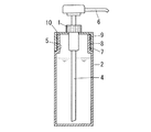
シャンプーやリンスなどの粘調な液体を所定量取り出す手押しポンプ付き容器は、近年の資源保護の観点から、中身を使い切った後、中身を補充して再利用することが一般に行われている。これらのほとんどは、図17のように、ポンプ部分1が、容器本体2の中央上方部にある細くなった首部3のネジ部にとめることで、容器の蓋を兼ねて容器を密封しており、内容液を詰め替える際には、ポンプ部分1だけでなくチューブ4まで抜き取った上で、詰め替え容器から内容液を注ぐことが一般に行われている。ただし、内容液の詰め替え作業は、首部3の穴5が小さいためやや難しく、例えば特許文献1に記載のように、漏斗を使うなどして作業を簡略化することが検討されている。   From the viewpoint of resource conservation in recent years, a container with a hand pump that takes out a predetermined amount of viscous liquid such as shampoo or rinse is generally replenished and reused after it has been used up. Most of these, as shown in FIG. 17, the pump portion 1 is fastened to the threaded portion of the narrow neck portion 3 at the center upper portion of the container body 2, so that the container is sealed as well as the container lid. When refilling the content liquid, it is common practice to pour out the content liquid from the refill container after extracting not only the pump part 1 but also the tube 4. However, the refilling operation of the content liquid is somewhat difficult because the hole 5 of the neck portion 3 is small. For example, as described in Patent Document 1, it is considered to simplify the operation by using a funnel.

また、詰め替えの作業を簡略化するために、中身のみを詰め替えるのではなく、詰め替え用の内容液を含む袋をそのまま容器本体としてしまう方法が、特許文献2に記載されている。   Moreover, in order to simplify the refilling work, Patent Document 2 describes a method in which a bag containing a refilling content liquid is used as it is as a container body, instead of refilling only the contents.

特開2005−225561号公報JP 2005-225561 A 特開2005−59947号公報JP 2005-59947 A

しかしながら、わざわざその他の道具を使うのは煩わしく、その道具が無いと詰め替えが困難となってしまうため、道具を使わずに容易な詰め替えを可能にする必要があった。また、特許文献2のように袋を容器とするには袋の材質が耐久力のあるアルミなどに限定されてしまい、再利用を促進させる観点からは好ましくない場合もあった。   However, it is cumbersome to use other tools, and it would be difficult to refill without the tools, so it was necessary to enable easy refilling without using tools. Further, as in Patent Document 2, in order to use a bag as a container, the material of the bag is limited to durable aluminum or the like, which is not preferable from the viewpoint of promoting reuse.

このため、図18に示すように、容器本体2の上部開放部分を径が大きいままの大径部7とし、この大径部7に螺合部8を設けて、同様に径を大きくした蓋10の螺合部9と螺合させることで開放部を開閉できるようにして、液の詰め替えを容易にすることも検討されたが、螺合部8,9が大きいために螺合がゆるみやすく、液漏れを起こすことがあった。また、容器本体2と蓋10とは、詰め替え時に別々に外さざるを得ないため、取り外した蓋10をチューブ4に付着している液が滴らないように逆さまに置いたりするといった工夫を使用者に強いるため、取り扱い上も不便であり、一般的に多用されるまでには至っていない。   Therefore, as shown in FIG. 18, the upper open portion of the container body 2 is a large-diameter portion 7 with a large diameter, and a screw-engaging portion 8 is provided in the large-diameter portion 7 to similarly increase the diameter. Although it has been studied that the opening portion can be opened and closed by screwing with the ten screwing portions 9 to facilitate refilling of the liquid, the screwing portions 8 and 9 are large, so that the screwing is easily loosened. The liquid leaked. Further, since the container body 2 and the lid 10 must be removed separately when refilling, the device is used such that the removed lid 10 is placed upside down so that the liquid adhering to the tube 4 does not drip. It is inconvenient to handle because it is resistant to the general public, and has not yet been used frequently.

そこでこの発明は、手押しポンプ付き容器の詰め替えのための穴を広く開放し、内容液を詰め替えやすくした容器を提供することを目的とする。   In view of this, an object of the present invention is to provide a container in which a hole for refilling a container with a hand pump is widely opened to facilitate refilling of the content liquid.

この発明は、容器本体の上部開放部が、蓋を嵌合することで密閉されるようにし、ヒンジ式連結部を介して接続された蓋及び容器本体に、蓋を開放した状態を保持可能なストッパーを設けることで、上記の課題を解決したのである。   According to the present invention, the upper open part of the container main body is sealed by fitting the lid, and the lid and the container main body connected via the hinge-type connecting part can hold the opened state. By providing the stopper, the above-mentioned problem has been solved.

すなわち、蓋をネジ止めではなく、容器本体の上部開放部と嵌合して密封するようにすることで、上部開放部を大きく広げることができるようになる。また、蓋と容器本体とがヒンジ式連結部で接続されつつ、蓋を開放した状態でストッパーにより保持されるため、ポンプの付いた蓋を外して別途置き場所を考える必要なく、蓋が開いたままの状態でそのまま内容液を詰めることができる。   That is, the upper open portion can be greatly widened by fitting the lid with the upper open portion of the container body and sealing it, not by screwing. In addition, since the lid and the container body are connected by a hinge-type connecting part and held by the stopper with the lid open, the lid opens without having to remove the lid with the pump and think about the place to place it separately. The contents liquid can be filled as it is.

この発明にかかる容器により、従来の詰め替え容器に比べて上部開放部を大きくすることができ、内容液の詰め替え作業を容易にすることができる。また、蓋を容器本体から外す必要なく開放状態で保持できるために、蓋とともにポンプを外すことで内容液を外部に付着させて汚したりすることなく、開放状態の広い上部開放部を通じてスムーズな詰め替え作業を行うことができる。   By the container concerning this invention, an upper open part can be enlarged compared with the conventional refill container, and the refilling operation | work of a content liquid can be made easy. In addition, since the lid can be held in an open state without having to be removed from the container body, it can be smoothly refilled through the wide open top of the open state without removing the pump together with the lid and causing the content liquid to adhere to the outside. Work can be done.

以下、この発明を図1乃至図14を用いて詳細に説明する。
この発明にかかるポンプ付き容器とは、ポンプ11により、容器本体14内に収容した内容液20を、チューブ12を通じて吸い上げて、供出口19から供出するものである。ここで用いる内容液20は、ポンプ11を1回〜数回押して供出される量が1度の使用量となる薬液を用いるとよく、粘調な液体であってもよい。具体的には、リンス、コンディショナー、シャンプー、トリートメント等の洗髪料及び頭髪用化粧品類、下地用、美白用クレンジング用などのクリーム、化粧水等の仕上げ又は皮膚用化粧品類、洗顔クリーム、ハンドソープ、ボディソープ等の皮膚用洗浄剤、日焼け止め用又は日焼け用の化粧品類、皮膚防護剤、殺菌剤、痒み止め剤等の医療用塗布剤類、衣類用液体洗剤、台所用液体洗剤等の洗剤類、糊や接着剤等の事務用品類、調味料などが挙げられる。これらの中でも、使用後に内容液20を詰め替えて補給し、長期間に亘って同じ容器で使用し続けても劣化が少ない薬剤を用いると好ましい。
The present invention will be described in detail below with reference to FIGS.
The container with a pump according to the present invention is a device in which the content liquid 20 accommodated in the container main body 14 is sucked up through the tube 12 by the pump 11 and delivered from the outlet 19. As the content liquid 20 used here, a chemical liquid that is used once when the pump 11 is pushed once to several times may be used, or a viscous liquid may be used. Specifically, rinses, conditioners, shampoos, treatments, etc. for hair washing and hair cosmetics, creams for bases, whitening cleansings, cosmetics for skin lotions, skin cosmetics, facial creams, hand soaps, Skin soaps such as body soaps, sunscreen or sunscreen cosmetics, skin protection agents, bactericides, anti-itching agents and other medical coatings, clothing detergents and kitchen detergents Office supplies such as glue and adhesives, seasonings and the like. Among these, it is preferable to refill the content liquid 20 after use and use a drug that has little deterioration even if it is continuously used in the same container for a long period of time.

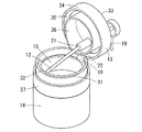
この発明にかかるポンプ付き容器の構成は、蓋13と容器本体14とからなり、容器本体14の上端面にある上部開放部15が、蓋13を嵌合することで密閉されうるものである。ネジ式ではなく、嵌合により密閉することで、上部開放部15をネジ式による場合よりも広く確保することができ、内容液20の詰め替えを容易にすることが出来る。   The configuration of the container with a pump according to the present invention includes a lid 13 and a container main body 14, and an upper open portion 15 on the upper end surface of the container main body 14 can be sealed by fitting the lid 13. The upper opening 15 can be secured wider than the screw type by sealing by fitting instead of the screw type, and the refilling of the content liquid 20 can be facilitated.

蓋13にはポンプ11を設けてあり、このポンプ11の容器本体14側にある吸入口21に、容器本体14の底部まで到達するチューブ12が繋がっている。ポンプ11は、このチューブ12を通じて、容器本体14に詰めた内容液20を吸い上げて容器外部へ向けた供出口19へ供出する。このポンプ11は図1に記載のような手押しポンプでもよいし、電池等で駆動する電動ポンプでもよい。   The lid 13 is provided with a pump 11, and a tube 12 that reaches the bottom of the container body 14 is connected to an inlet 21 on the container body 14 side of the pump 11. The pump 11 sucks up the content liquid 20 packed in the container main body 14 through the tube 12 and delivers it to the outlet 19 toward the outside of the container. The pump 11 may be a hand pump as shown in FIG. 1 or an electric pump driven by a battery or the like.

容器本体14は、図のような円筒形に限らず、角柱形でもよいし、その他容器として使用可能な形状であればよい。ただし、上部開放部15は、密閉度を高め、転倒した際に内容物が漏れたりしないように、円形又は角に大きなアールを設けた角型であると好ましい。   The container body 14 is not limited to the cylindrical shape as shown in the figure, but may be a prismatic shape or any other shape that can be used as a container. However, it is preferable that the upper open portion 15 has a circular shape or a square shape with a large rounded corner so that the content is not leaked when the top opening portion 15 is overturned.

蓋13と容器本体14とは、ヒンジ式連結部16を介して接続されており、蓋13を開放した際にも、別途取り外す必要がなく、取り付けたままにしておくことができる。また、蓋13と容器本体14とは、蓋13を開放した状態で保持可能なストッパーを備えている。このため、内容液20に濡れているチューブ12を取り外す必要が無く床等に接触させて内容液20で濡らすことなく、蓋13を開けたままで詰め替え作業を行うことができる。   The lid 13 and the container main body 14 are connected via a hinge-type connecting portion 16, and even when the lid 13 is opened, it is not necessary to remove it separately and can remain attached. The lid 13 and the container main body 14 are provided with a stopper that can be held in a state where the lid 13 is opened. For this reason, it is not necessary to remove the tube 12 that is wet with the content liquid 20, and the refilling operation can be performed while the lid 13 is opened without being brought into contact with the floor or the like and getting wet with the content liquid 20.

ヒンジ式連結部16、通常、図示するような合成樹脂等の屈曲可能な材質(可撓性材料)からなる板状小片によって構成されるが、近年開発されている種々の形態の物が使用可能である。例えば、板状小片の厚さに変化を与え、柔らかく開閉可能としたもの、板状小片を波板状、すなわち蛇腹状としたもの等があるが、開閉の強弱等に応じ、適宜選択すればよい。また、互い違いに組み合わせた板の間をピンで軸支した通常の蝶番のような構成も可能である。   The hinge-type connecting portion 16 is usually constituted by a plate-shaped piece made of a bendable material (flexible material) such as a synthetic resin as shown in the figure, but various forms that have been developed in recent years can be used. It is. For example, there is a change in the thickness of the plate-like piece so that it can be opened and closed softly, a plate-like piece made into a corrugated plate shape, that is, a bellows shape, etc. Good. Moreover, the structure like the normal hinge which pivotally supported with the pin between the board | plates which combined alternately is also possible.

この発明にかかる容器は、通常用いられる詰め替え容器と同様に、蓋13が天板33と容器本体14の上部開放部15の周囲を覆う周壁34とを有し、これらによって、容器が転倒しても内容物が漏れ出さない密閉度を備える。   In the container according to the present invention, the lid 13 has the top plate 33 and the peripheral wall 34 that covers the periphery of the upper open portion 15 of the container main body 14 in the same manner as a normally used refill container. Has a sealing level that prevents the contents from leaking out.

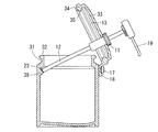
この発明にかかる容器が有する上記のストッパーの構造は、種々の形態が可能である。例えば、図1乃至図3に示すように、蓋13の密閉時には容器本体14の縁部32の内側に接触する位置となる、ヒンジ式連結部16寄りの箇所に、蓋13の天板33から内面側に突出片36を設けた構造が挙げられる。この突出片36は、図1に示すように、蓋13を開放した際に突出片36の先端部近傍が容器本体14の上部開放部15の縁部32に接触して、蓋13が閉じるのを防止する上記ストッパーとして働く。   Various forms are possible for the structure of the stopper of the container according to the present invention. For example, as shown in FIG. 1 to FIG. 3, when the lid 13 is sealed, the top plate 33 of the lid 13 is placed at a position near the hinged connecting portion 16 that is in contact with the inside of the edge portion 32 of the container body 14. The structure which provided the protrusion piece 36 in the inner surface side is mentioned. As shown in FIG. 1, when the lid 13 is opened, the projecting piece 36 comes into contact with the edge 32 of the upper open portion 15 of the container body 14 at the vicinity of the tip of the projecting piece 36 so that the lid 13 is closed. Acts as a stopper to prevent the above.

突出片36の形状は特に限定されるものではなく、例えば、図1及び図2に示すように、リング状で、外径を容器本体14の縁部32とほぼ同一とすれば、蓋13を閉じた際に蓋13と容器本体14との密閉性がより向上する。   The shape of the protruding piece 36 is not particularly limited. For example, as shown in FIGS. 1 and 2, if the outer diameter is substantially the same as the edge 32 of the container main body 14 as shown in FIGS. When closed, the sealing property between the lid 13 and the container body 14 is further improved.

また突出片36の形状の他の例として、蓋13の天板33から、少なくともヒンジ式連結部16側をカバーするようにした図3に記載のようなリングの一部が欠けた弧状や、舌片状、板状などの形状として、同様に蓋13を開放した際に突出片36の先端部近傍が容器本体14の縁部32に接触して、蓋13が閉じるのを防止するストッパーとしてもよい。   Further, as another example of the shape of the projecting piece 36, the top plate 33 of the lid 13 covers at least the hinge-type connecting portion 16 side, as shown in FIG. As a stopper such as a tongue-like shape or a plate-like shape, when the lid 13 is similarly opened, the vicinity of the tip of the protruding piece 36 contacts the edge 32 of the container main body 14 to prevent the lid 13 from closing. Also good.

天板33には、上記のポンプ11が設けられており、供出口19が上方に、吸入口21とそれに繋がるチューブ12が下方に位置する。   The top plate 33 is provided with the pump 11 described above, and the outlet 19 is located above, and the suction port 21 and the tube 12 connected thereto are located below.

容器本体14の縁部32と、突出片36とが図1又は図3のように接触することで、蓋13がこの接触部分22と、ヒンジ式連結部16との二点で支えられ、それ以上蓋13が閉まろうとする動きを止めるストッパーとなるので、蓋13を開放した状態を保持することができる。ここで縁部32と接触する箇所は、図1のように突出片36の側壁面であってもよいし、図3のように縁や先端部であってもよい。   The edge portion 32 of the container body 14 and the protruding piece 36 come into contact with each other as shown in FIG. 1 or FIG. Since the stopper that stops the movement of the lid 13 being closed is used as described above, the lid 13 can be kept open. Here, the portion in contact with the edge portion 32 may be the side wall surface of the protruding piece 36 as shown in FIG. 1, or may be the edge or the tip portion as shown in FIG.

ヒンジ式連結部16は、後述する図8のように蓋13の天板33に直接接続されていてもよいし、図1に示すように周壁34に接続されているものでもよい。   The hinge-type connecting portion 16 may be directly connected to the top plate 33 of the lid 13 as shown in FIG. 8 described later, or may be connected to the peripheral wall 34 as shown in FIG.

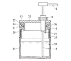
また、蓋13の周壁34の内側に図2乃至図7のような環状張り出し部35を設け、これと嵌合するように、容器本体14の縁部32の下部に、外周が縮まった縮径部31を設けてあると、嵌合された蓋13が確実に密閉されるためより好ましい。さらに、蓋13の突出片36が全周に亘るものであり、密閉時に上部開放部15の全周で容器本体14と接すると、密閉性が高まりより好ましい。これらの嵌合する部分は、いずれも変形可能な樹脂製であると、嵌め合わせやすく、密閉しやすいので好ましい。   Further, an annular projecting portion 35 as shown in FIGS. 2 to 7 is provided on the inner side of the peripheral wall 34 of the lid 13, and the diameter is reduced at the lower portion of the edge portion 32 of the container body 14 so as to be fitted therewith. It is more preferable that the portion 31 is provided because the fitted lid 13 is reliably sealed. Furthermore, the protruding piece 36 of the lid 13 extends over the entire circumference, and it is more preferable that the container 13 is in contact with the entire circumference of the upper opening 15 at the time of sealing to improve the sealing performance. These fitting portions are preferably made of a deformable resin because they can be easily fitted and sealed.

なお、突出片36のうち、少なくともヒンジ式連結部16寄りの部分は、壁面が縁部32と接触するだけの高さを有することが必要であるが、突出片36が全周に亘るものである場合、ヒンジ式連結部16寄りでない部分が高すぎると、蓋13を嵌め合わせる際に邪魔になることがあるため、図1に示すように突出片36はヒンジ式連結部16に近い部分が他の部分より図1のように高くなっているとより好ましい。   Of the protruding piece 36, at least the portion near the hinge-type connecting portion 16 needs to have a height sufficient for the wall surface to come into contact with the edge portion 32, but the protruding piece 36 extends over the entire circumference. In some cases, if the portion that is not close to the hinge-type connecting portion 16 is too high, it may interfere with the fitting of the lid 13, so that the protruding piece 36 has a portion close to the hinge-type connecting portion 16 as shown in FIG. It is more preferable that the height is higher as shown in FIG.

また、上記ストッパーを有する容器の別の構造としては、例えば、図4及び図5に記載のような構造が挙げられる。
すなわち、蓋13を開いた際に、チューブ12の先端23が容器本体14の壁面に接触し、チューブ12が突っ張り、つっかい棒の役目を果たすことで、蓋13を開放状態で留めるストッパーとするものである。この場合、チューブ12は蓋13を支えることができるだけの弾性力を有していることが必要であるとともに、蓋13の開放時に容器本体14の壁面に届くだけの長さを有していることが必要となる。先端23が接触する箇所は、容器本体14の壁面の上方であるほど蓋13が大きく開放されるため、上部開放部15の近傍に接触するものであると好ましい。
Moreover, as another structure of the container which has the said stopper, the structure as described in FIG.4 and FIG.5 is mentioned, for example.
That is, when the lid 13 is opened, the distal end 23 of the tube 12 comes into contact with the wall surface of the container main body 14, and the tube 12 is stretched to serve as a sticking rod, thereby providing a stopper that holds the lid 13 in an open state. Is. In this case, the tube 12 needs to have an elastic force that can support the lid 13 and has a length that can reach the wall surface of the container body 14 when the lid 13 is opened. Is required. The location where the tip 23 comes into contact with the upper open portion 15 is preferably close to the upper open portion 15 because the lid 13 is greatly opened as it is above the wall surface of the container body 14.

このような構造において、チューブ12は、少なくとも先端部近くを弾性変形可能な材質とすることにより、図5のようにチューブ12の先端が屈曲した状態で容器本体14の上部開放部15近傍に接触してつっかい棒状態となる。この構造の場合、容器本体14が縦に長く、底部の最も深いところまで届かせるためにチューブ12を長くしても、ポンプ11の取り付け位置をヒンジ式連結部16近くにする必要が無く、蓋13の中央付近に設けることが出来る。   In such a structure, the tube 12 is made of a material that can be elastically deformed at least near the tip, thereby contacting the vicinity of the upper open portion 15 of the container body 14 with the tip of the tube 12 bent as shown in FIG. It becomes a sticky state. In the case of this structure, even if the tube 12 is lengthened in order to reach the deepest part of the bottom portion of the container body 14 in the vertical direction, it is not necessary to make the mounting position of the pump 11 close to the hinge-type connecting portion 16, and the lid 13 near the center.

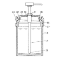
また、チューブ12を突っ張らせて上記ストッパーとする別の構造としては、図6及び図7に記載の構造が挙げられる。
容器本体14は、内側の壁面上部の上部開放部15の近傍に、チューブ12の先端23を乗せておくことが可能な、くぼみ又は溝である乗掛部38を有している。蓋13を開放する際には、ヒンジ式連結部16が曲がることでチューブ12の先端23が容器本体14の底部から離れて、ヒンジ式連結部16の対角に位置する壁面に近づく。このチューブ12の先端部を乗せておくため、この乗掛部38は、ヒンジ式連結部16の対面側又は対面斜め側となる容器本体14の内側の壁面上部に設けられているとよい。
Moreover, as another structure which makes the tube 12 stretch and uses it as the said stopper, the structure of FIG.6 and FIG.7 is mentioned.
The container main body 14 has a hanging portion 38 that is a recess or a groove in which the tip 23 of the tube 12 can be placed in the vicinity of the upper opening portion 15 at the upper portion of the inner wall surface. When opening the lid 13, the hinge-type connecting portion 16 is bent so that the tip 23 of the tube 12 is separated from the bottom portion of the container body 14 and approaches the wall surface located diagonally of the hinge-type connecting portion 16. In order to place the distal end portion of the tube 12, the hanging portion 38 is preferably provided on the upper surface of the inner wall of the container main body 14 on the facing side or the diagonally facing side of the hinge type connecting portion 16.

この乗掛部38に、図7のように、チューブ12の先端23を乗せて、チューブ12を突っ張らせて、つっかい棒とすることで、上記ストッパーとして、蓋13を開放した状態で保持可能にすることができる。この構造の場合、チューブ12は蓋13の重量を支えておくことができる程度の固さを有している必要がある。また一方でチューブ12は、先端23を容易に乗掛部38に乗せられるようにある程度の可撓性を有していると好ましい。さらに、乗掛部38は壁面の上部開放部15近傍にあることが、蓋13の十分な開放のために望ましい。   As shown in FIG. 7, the tip end 23 of the tube 12 is put on the hanging portion 38 and the tube 12 is stretched to form a stick, so that the stopper 13 can be held with the lid 13 open. Can be. In the case of this structure, the tube 12 needs to be hard enough to support the weight of the lid 13. On the other hand, it is preferable that the tube 12 has a certain degree of flexibility so that the tip 23 can be easily placed on the riding portion 38. Furthermore, it is desirable for the riding portion 38 to be in the vicinity of the upper opening 15 of the wall surface in order to sufficiently open the lid 13.

また、チューブ12は、その長さが、蓋13を開放して保持する状態での乗掛部38までの長さに等しいと好ましい。従って、ポンプ11をヒンジ式連結部16に近い側に設けて、乗掛部38とポンプ11との距離を大きく取ると、底が深い容器に合わせて長くしたチューブ12にも対応できるため好ましい。一方で、チューブ12の一部が弾性変形可能な材質によるものである場合は、前記の乗掛部38を容器本体14の上部開放部15よりも比較的下方に設けることが可能となるので、チューブ12は乗掛部38までの長さよりも長いものでもよい。さらに、このチューブ12は上記のように、内容液20を吸い上げる必要があるため、容器本体14の底部までの長さを有している必要があり、弾性変形可能な材質であると図4のようにチューブ12を長くしてもよいため好ましい。   Moreover, it is preferable that the length of the tube 12 is equal to the length to the riding portion 38 in a state where the lid 13 is opened and held. Therefore, it is preferable to provide the pump 11 on the side close to the hinge-type connecting portion 16 and to increase the distance between the riding portion 38 and the pump 11 because it is possible to cope with the tube 12 having a long bottom according to the container having a deep bottom. On the other hand, when a part of the tube 12 is made of a material that can be elastically deformed, the above-described hanging portion 38 can be provided relatively lower than the upper opening portion 15 of the container body 14, The tube 12 may be longer than the length up to the riding portion 38. Furthermore, since the tube 12 needs to suck up the content liquid 20 as described above, the tube 12 needs to have a length up to the bottom of the container main body 14 and is made of an elastically deformable material as shown in FIG. Thus, the tube 12 may be lengthened, which is preferable.

このようにチューブ12を突っ張らせ、つっかい棒として上記ストッパーを実現する場合、蓋13と容器本体14との嵌合する構造については特に限定されるものではない。例えば、図3に記載のように、蓋13の天板33の周囲に周壁34を設け、この周壁34に内側に張り出した環状張り出し部35を設け、この環状張り出し部35と嵌め合わせられるように容器本体14の上部開放部15に、外周が縮んだ縮径部31を設けて、嵌め合わせることで、蓋13を密閉する構造が挙げられる。   In this way, when the tube 12 is stretched to realize the stopper as a stick, the structure in which the lid 13 and the container body 14 are fitted is not particularly limited. For example, as shown in FIG. 3, a peripheral wall 34 is provided around the top plate 33 of the lid 13, an annular projecting portion 35 projecting inward is provided on the peripheral wall 34, and the annular projecting portion 35 can be fitted together. The structure which seals the lid | cover 13 by providing the diameter reduction part 31 which the outer periphery shrunk in the upper open part 15 of the container main body 14, and fitting together is mentioned.

一方、上記のように例示した上記ストッパーをより確実に働かせるために、蓋13に連結したヒンジ式連結部16が蓋13を閉める方向に付勢するものであると、蓋13が上部開放部15から離れて下方へ倒れるようなことがないのでより好ましい。また、閉じる方向に付勢された蓋13が上記ストッパーにより止められることで、蓋13を開放したまま保持する状態での安定性が高まる。具体的には、ヒンジ式連結部16が、弾性のあるゴムや樹脂等からなり、屈曲された場合に元に戻る力により、蓋13を閉めるようにするとよい。   On the other hand, in order for the stopper illustrated as described above to work more reliably, when the hinge-type connecting portion 16 connected to the lid 13 is biased in the direction in which the lid 13 is closed, the lid 13 becomes the upper opening portion 15. It is more preferable because it does not fall down from the center. In addition, since the lid 13 biased in the closing direction is stopped by the stopper, stability in a state where the lid 13 is held open is increased. Specifically, the hinge-type connecting portion 16 is made of elastic rubber, resin, or the like, and the lid 13 may be closed by a force that returns to the original when bent.

その構造としては、図1及び図2、図4及び図5のように、蓋13が板状の樹脂であるヒンジ式連結部16を介して環状バンド37と接続しており、この環状バンド37を容器本体14の外側で、縮径部31より下の帯状部分に嵌めることで、蓋13と容器本体14とを連結した構造が挙げられる。この場合、ヒンジ式連結部16及び環状バンド37は同種の樹脂等からなり、環状バンド37を、力を加えて拡張したり、容器本体14の縁部32を押し縮めたりすることで、前記帯状部分に嵌めやすくなっている。また、変形可能な樹脂等からなるヒンジ式連結部16は、蓋13の開放時には曲げられ、それが元に戻ろうとする力により、蓋13を閉める方向に付勢するものである。   As shown in FIGS. 1, 2, 4, and 5, the lid 13 is connected to an annular band 37 via a hinge-type connecting portion 16 that is a plate-like resin. A structure in which the lid 13 and the container main body 14 are connected to each other by fitting them in a band-like part below the reduced diameter part 31 outside the container main body 14 can be mentioned. In this case, the hinge-type connecting portion 16 and the annular band 37 are made of the same kind of resin or the like, and the annular band 37 is expanded by applying a force, or the edge portion 32 of the container body 14 is compressed and contracted, thereby It is easy to fit in the part. Further, the hinge-type connecting portion 16 made of a deformable resin or the like is bent when the lid 13 is opened, and is biased in the direction in which the lid 13 is closed by a force for returning it.

また、ヒンジ式連結部16の別の構造として、図3及び図6,図7に記載のように、容器本体14に設けられた係合片17に、蓋13の周壁34に繋がり、係合片17を引掛け片18とを係合することで、これらの係合片17と引掛け片18とによってヒンジ式連結部16を形成し、蓋13と容器本体14とを連結する構造が挙げられる。この場合、係合片17は弾力性が少なく容器本体14に固定されているものでよいが、引掛け片18は係合片17によって固定されつつ、蓋13を開くことで曲がったり戻ったり変形する役を為し、かつ、それが元に戻る力によって蓋13を閉める方向に付勢するものであるため、弾性のあるゴム又は樹脂等であることが好ましい。   Further, as another structure of the hinge-type connecting portion 16, as shown in FIGS. 3, 6, and 7, the engaging piece 17 provided on the container body 14 is connected to the peripheral wall 34 of the lid 13 and is engaged. By engaging the piece 17 with the hooking piece 18, the engaging piece 17 and the hooking piece 18 form a hinge-type connecting portion 16 to connect the lid 13 and the container body 14. It is done. In this case, the engaging piece 17 may be fixed to the container body 14 with little elasticity, but the hooking piece 18 is fixed by the engaging piece 17 and bent or returned or deformed by opening the lid 13. It is preferable to use elastic rubber, resin, or the like because it is biased in the direction of closing the lid 13 by the force of returning to the original.

この係合片17と引掛け片18との構造の一例を図8(a)乃至(d)に示す。
図8(a)に示した係合片17及び引掛け片18の構造は、蓋13から繋がる引掛け片18の先端が張り出した張り出し部分18aを有しており、この張り出し部分18aを容器本体14の側壁で輪を形成する係合片17に通した後は、張り出し部分18aが係合片17に引っかかって抜き取ることが出来ない構造となる。なお、この場合、係合片17と引掛け片18の少なくとも一方は、張り出した部分を通すために弾性変形可能な材質である必要がある。
An example of the structure of the engaging piece 17 and the hooking piece 18 is shown in FIGS.
The structure of the engaging piece 17 and the hooking piece 18 shown in FIG. 8A has an overhanging portion 18a in which the tip of the hooking piece 18 connected to the lid 13 is overhanging, and this overhanging portion 18a is used as the container body. After passing through the engagement piece 17 forming a ring on the side wall of 14, the protruding portion 18a is caught by the engagement piece 17 and cannot be removed. In this case, at least one of the engaging piece 17 and the hooking piece 18 needs to be made of a material that can be elastically deformed in order to pass the protruding portion.

また、図8(b)に示した係合片17及び引掛け片18の構造は、同様に蓋13から繋がる引掛け片18の先端が張り出した張り出し部分18aを有しており、容器本体14の側壁に設けられた一対の係合片17の間に引掛け片18を挟み込ませることで、張り出し部分18aが係合片17に引っかかって抜き取ることができない構造となる。この場合も、係合片17と引掛け片18の少なくとも一方は、張り出した部分を通すために弾性変形可能な材質である必要がある。   Further, the structure of the engaging piece 17 and the hooking piece 18 shown in FIG. 8B has an overhanging portion 18a in which the tip of the hooking piece 18 connected from the lid 13 is overhanging. When the hooking piece 18 is sandwiched between a pair of engaging pieces 17 provided on the side wall, the protruding portion 18a is caught by the engaging piece 17 and cannot be removed. Also in this case, at least one of the engaging piece 17 and the hooking piece 18 needs to be made of a material that can be elastically deformed in order to pass the protruding portion.

これらの図8(a)及び(b)に示した構造の場合、引掛け片18のヒンジ式連結部16に相当するスライド部分18bの長さを長くすることにより、引掛け片18が容器本体の側面に沿って上下方向にスライド可能となる。すなわち、蓋13を開放したときに、蓋13の位置に自由度が増える構造となり、より深さが広い容器、すなわちチューブ12が長い容器にも対応可能となる。ただし、上記ストッパーが作用する範囲の自由度でないと、蓋13を開放時に固定することが困難となるおそれがある。   In the case of the structure shown in FIGS. 8A and 8B, the length of the slide portion 18b corresponding to the hinge-type connecting portion 16 of the hook piece 18 is increased, so that the hook piece 18 becomes the container body. It becomes possible to slide up and down along the side surface. That is, when the lid 13 is opened, the degree of freedom increases in the position of the lid 13, and a container having a larger depth, that is, a container having a long tube 12 can be accommodated. However, if the degree of freedom is not within the range where the stopper acts, it may be difficult to fix the lid 13 when opened.

図8(c)及び(d)に示した構造は、係合片17が張り出し部分17aを有しており、引掛け片18は張り出し部分17aを通過可能な穴18cと、その穴18cと繋がっており、張り出し部分17aが通過できない径又は幅である狭部18dとを有している。張り出し部分17aが穴18cを通した後、引掛け片18を横にスライドさせて、張り出し部分17aを狭部18dに引っ掛けることで固定する。   In the structure shown in FIGS. 8C and 8D, the engaging piece 17 has an overhanging portion 17a, and the hooking piece 18 is connected to the hole 18c through which the overhanging portion 17a can pass and the hole 18c. And has a narrow portion 18d having a diameter or width through which the projecting portion 17a cannot pass. After the overhanging portion 17a passes through the hole 18c, the hooking piece 18 is slid sideways, and the overhanging portion 17a is hooked on the narrow portion 18d to be fixed.

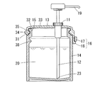
一方、このようなポンプ付き容器を密封する別の構造として、図9及び図10に記載の構造が挙げられる。これは、蓋13の周囲には溝部41が設けられており、この溝部41に、容器本体14の上方開放部15の縁部42が、掛け止め式に嵌め合わされることで、蓋13を密閉する。このため、溝部41内にはOリング状の弾性体からなるシール材を設けると好ましい。   On the other hand, as another structure for sealing such a container with a pump, there are structures shown in FIGS. This is because a groove 41 is provided around the lid 13, and the edge 42 of the upper opening 15 of the container body 14 is fitted into the groove 41 in a latching manner so that the lid 13 is sealed. To do. For this reason, it is preferable to provide a sealing material made of an O-ring elastic body in the groove 41.

ヒンジ式連結部16の対面側、又は斜め対面側となる容器本体14の外側に張り出し部44を設け、蓋13のヒンジ式連結部16の対面側等に、孔45を有する引っ掛け部46を設け、孔45に張り出し部44を通して引っ掛け部46を固定することで、蓋13を確実に密閉することができる。   An overhanging portion 44 is provided on the outer side of the container main body 14 facing the hinge-type connecting portion 16 or the diagonally facing side, and a hooking portion 46 having a hole 45 is provided on the facing side of the hinge-type connecting portion 16 of the lid 13. The lid 13 can be reliably sealed by fixing the hooking portion 46 through the overhanging portion 44 in the hole 45.

いずれの構造であっても、蓋13の天板33上におけるポンプ11の位置は、蓋13の天板33の中央よりもヒンジ式連結部16寄りであることが望ましい。これにより、ヒンジ式連結部16を曲げて蓋13を開ける際に、チューブ12が上部開放部15のヒンジ式連結部16の対面側となる部分や内壁などに当接するまでの距離が長くなる。この発明にかかるポンプ付き容器であると、従来の詰め替え容器において蓋をネジ止めするために容器本体14の成形の際に中心付近にネジ部のついた口部を設けるのとは違い、容器本体14の上端面を十分に開放し、蓋13の任意の位置にポンプ11を設けることができるようになるため、ポンプ11の位置をより好ましい位置に変更することが容易である。   In any structure, it is desirable that the position of the pump 11 on the top plate 33 of the lid 13 is closer to the hinge-type connecting portion 16 than the center of the top plate 33 of the lid 13. Thereby, when the hinge-type connection part 16 is bent and the cover 13 is opened, the distance until the tube 12 abuts against the part of the upper opening part 15 facing the hinge-type connection part 16 or the inner wall becomes longer. In the container with a pump according to the present invention, the container body is different from the conventional refillable container in that a mouth with a threaded portion is provided near the center when the container body 14 is formed to screw the lid. Since the upper end surface of 14 is sufficiently opened and the pump 11 can be provided at an arbitrary position of the lid 13, it is easy to change the position of the pump 11 to a more preferable position.

特に、図6、7,9,10の構造の場合、ポンプ11の取り付け位置がヒンジ式連結部16寄りであると、その分対角となる箇所にある乗掛部38にチューブ12の先端23を乗せやすくなるのでより好ましい。また、ポンプ11の位置を蓋13の中央よりも外縁に近づけて、供出口19の先端が容器本体14よりも外側に位置するようにすると、供出口19から供出された内容液20を手に取るために供出口19の下に手を差し伸べやすくなり、ポンプ部分が扱いやすくなる。   In particular, in the case of the structure shown in FIGS. 6, 7, 9, and 10, if the mounting position of the pump 11 is closer to the hinge-type connecting portion 16, the distal end 23 of the tube 12 is placed on the hanging portion 38 at the opposite corner. It is more preferable because it becomes easier to place. Further, when the position of the pump 11 is closer to the outer edge than the center of the lid 13 and the tip of the outlet 19 is positioned outside the container body 14, the content liquid 20 delivered from the outlet 19 is obtained by hand. It is easy to reach under the outlet 19 to take it, and the pump part is easy to handle.

また、いずれの構造であっても、容器本体14の底面は、傾斜を有していると好ましい。傾斜を有していることで、内容液20が一箇所に集まりやすくなり、残量が少なくなったときでも吸い上げやすくなる。これに合わせて、図4に記載のように、蓋13を密閉した際にチューブ12の先端が、容器本体の底のうち最も深い部分に到達するようになっていると、内容液20をできるだけ使い切ってから詰め替えを行うことができるためより好ましい。すなわち、ポンプ11から延びるチューブ12の先端位置を蓋13の中央からヒンジ式連結部16寄りにした場合、前記最深部はそれに合わせてヒンジ式連結部16がある方向に寄るものとする。   In any structure, the bottom surface of the container body 14 is preferably inclined. By having the inclination, the content liquid 20 is easily collected in one place, and it is easy to suck up even when the remaining amount is low. In accordance with this, as shown in FIG. 4, if the tip of the tube 12 reaches the deepest part of the bottom of the container body when the lid 13 is sealed, the content liquid 20 can be as much as possible. It is more preferable because it can be refilled after it is used up. That is, when the distal end position of the tube 12 extending from the pump 11 is moved closer to the hinge type connecting part 16 from the center of the lid 13, the deepest part approaches the direction in which the hinge type connecting part 16 exists accordingly.

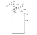
なお、上記の環状バンド37を用いて蓋13を容器本体14と連結する場合、図11のように、蓋13と環状バンド37との間に、板状の樹脂からなるヒンジ式連結部16から延びて、蓋13と環状バンド37との間を、全周に亘って繋ぐ切り離しベルト48を有していると好ましい。この切り離しベルト48は、手で蓋13及び環状バンド37から切り離し可能であり、図12のように一度切り離したら、元に戻せないものである必要がある。材質としては、樹脂フィルムや紙であってもよく、環状バンド37と同一の樹脂素材であってもよい。このような切り離しベルト48を有していると、蓋13を一度でも開封する際には、図12のようにこの切り離しベルト48を切り離さなければならなくなり、開封済みか開封済みで無いかを、切り離しベルト48の状況によって判断することができる。これにより、店頭で開封されて中身が入れ替えられたり、異物を混入されたりした場合に、すぐに異常であると気づくことができる。また、周囲を固定するため、密閉性を高めることが出来る。なお、図11及び図12ではストッパーを省略している。   In addition, when connecting the lid | cover 13 with the container main body 14 using said cyclic | annular band 37, as shown in FIG. 11, between the lid | cover 13 and the cyclic | annular band 37, from the hinge-type connection part 16 which consists of plate-shaped resin. It is preferable to have a separation belt 48 that extends and connects the lid 13 and the annular band 37 over the entire circumference. This separation belt 48 can be separated from the lid 13 and the annular band 37 by hand, and once separated as shown in FIG. 12, it must be unreturnable. The material may be a resin film or paper, or the same resin material as the annular band 37. Having such a separation belt 48, when opening the lid 13 even once, it is necessary to separate this separation belt 48 as shown in FIG. 12, and whether it is opened or not opened, This can be determined according to the situation of the separation belt 48. Thereby, when it is opened at the store and the contents are replaced or foreign matter is mixed in, it can be immediately recognized as abnormal. Moreover, since the periphery is fixed, the airtightness can be improved. In addition, the stopper is abbreviate | omitted in FIG.11 and FIG.12.

また、同様に上記の環状バンド37を用いて蓋13と容器本体14とを連結する場合、板状であるヒンジ式連結部16の、蓋13と環状バンド37との間の二辺を、図13のように、一方の辺51を他方の辺52より長くすることも考えられる。二辺の長さが同じ場合には、図14のように、蓋13の開放時にチューブ12が直径方向すなわち上部開放部15の中央部方向に位置し、詰め替え容器の構造によっては内容液20の入れ替え時に邪魔となる場合も考えられる。しかし、図13のように一方の辺51が長いと、蓋13を開放した際に、他方の短い辺52側に蓋13が傾いて、図15のようにチューブ12の向く角度が変わる。これにより、上部開放部15の中央部分が大きく開放された状態となり、内容液20の詰め替えがよりやりやすくなる。   Similarly, when the lid 13 and the container body 14 are connected using the annular band 37, two sides of the hinge-type connecting portion 16 that is plate-shaped between the lid 13 and the annular band 37 are shown in FIG. It is also conceivable that one side 51 is longer than the other side 52 as in FIG. When the lengths of the two sides are the same, as shown in FIG. 14, the tube 12 is positioned in the diameter direction, that is, in the direction of the center of the upper opening 15 when the lid 13 is opened. It may be a hindrance when replacing. However, if one side 51 is long as shown in FIG. 13, when the lid 13 is opened, the lid 13 tilts toward the other short side 52, and the angle to which the tube 12 faces changes as shown in FIG. Thereby, the center part of the upper opening part 15 will be in the state open | released largely, and it will become easier to refill the content liquid 20. FIG.

さらに、図16(a)乃至(c)に同様の効果を発揮するヒンジ式連結部16の別の構造を示す。これは、図8(b)に示した、引掛け片18を一対の係合片17で挟む構造と同様の機構であって、スライド部分18bを含む引掛け片18全体を円弧状に形成したものであり、引掛け片18の一方の辺51が他方の辺52より長くなっている。この場合、図13に示した構造と同様に、蓋13の開放時に、チューブ12を容器本体14の上部開放部15の中心からずらした位置に上げることが出来る。なお、図16(b)は蓋13を閉めた状態であり、図16(c)は引掛け片18を係合片17から外した状態の図である。   Further, FIGS. 16A to 16C show another structure of the hinge-type connecting portion 16 that exhibits the same effect. This is a mechanism similar to the structure shown in FIG. 8B in which the hook piece 18 is sandwiched between the pair of engaging pieces 17, and the entire hook piece 18 including the slide portion 18 b is formed in an arc shape. One side 51 of the hooking piece 18 is longer than the other side 52. In this case, similarly to the structure shown in FIG. 13, the tube 12 can be raised to a position shifted from the center of the upper opening 15 of the container body 14 when the lid 13 is opened. 16B shows a state in which the lid 13 is closed, and FIG. 16C shows a state in which the hooking piece 18 is removed from the engaging piece 17.

なおこの場合、チューブ12により突っ張らせてストッパーとするよりも、突出片36によりストッパーとすることが好ましい。チューブ12が壁面に対して斜めに接するため、固定しにくくなるためである。チューブ12を突っ張らせる場合、チューブ12を乗せる乗掛部38は、ヒンジ式連結部16の対角ではなく、斜めに向いたチューブ12の向く箇所に設けると好ましい。   In this case, it is preferable to use the protruding piece 36 as a stopper, rather than using the tube 12 as a stopper. This is because the tube 12 is in contact with the wall surface at an angle, making it difficult to fix. When the tube 12 is stretched, it is preferable that the hanging portion 38 on which the tube 12 is placed is provided not at the diagonal of the hinge-type connecting portion 16 but at a position where the tube 12 facing diagonally faces.

また、上記に示した以外にも、この発明にかかる容器の材料は、少なくとも嵌め合わせを行う部分は樹脂製であると好ましく、全体が樹脂製であってもよい。力を加えることで変形し、嵌め合わせが容易に出来るだけでなく、成形も容易となるためである。   In addition to the above, the container material according to the present invention is preferably made of resin at least at the portion to be fitted, and may be entirely made of resin. This is because it is deformed by applying force and not only can be easily fitted, but also molding is facilitated.

これらの例のような構造を有する容器により、従来のネジ型の蓋により密閉していたポンプ付き容器に比べて、内容液を詰め替えるための上部開放部を大きく確保することができる。さらにその上部開放部を、開いた状態で保持することができるので、内容液を使い切った際に、詰め替え用の内容液を詰める作業を容易に行うことができる。   With the container having the structure as in these examples, it is possible to secure a large upper open portion for refilling the content liquid, as compared with a container with a pump sealed with a conventional screw-type lid. Furthermore, since the upper open part can be held in the open state, when the content liquid is used up, the operation of filling the content liquid for refilling can be easily performed.

この発明にかかる容器の第一の構造例を示す外観図External view showing a first structural example of a container according to the present invention この発明にかかる容器の第一の構造例を示す断面図Sectional drawing which shows the 1st structural example of the container concerning this invention この発明にかかる容器の突出片の径が小さい構造例を示す断面図Sectional drawing which shows the structural example with a small diameter of the protrusion piece of the container concerning this invention この発明にかかる容器のチューブをストッパーとする構造例を示す断面図Sectional drawing which shows the structural example which uses the tube of the container concerning this invention as a stopper この発明にかかる容器のチューブをストッパーとする構造例を示す開放時の断面図Sectional drawing at the time of opening which shows the structural example which uses the tube of the container concerning this invention as a stopper この発明にかかる容器の乗掛部を有する構造例を示す断面図Sectional drawing which shows the structural example which has the boarding part of the container concerning this invention この発明にかかる容器の乗掛部を有する構造例を示す開放時の断面図Sectional drawing at the time of opening which shows the structural example which has a hanging part of the container concerning this invention (a)〜(d)ヒンジ式連結部の例を示す図(A)-(d) The figure which shows the example of a hinge type connection part この発明にかかる容器の掛け止め式に密閉する構造例を示す断面図Sectional drawing which shows the structural example sealed to the latching type of the container concerning this invention この発明にかかる容器の掛け止め式に密閉する構造例を示す開放時の断面図Sectional drawing at the time of opening which shows the structural example sealed in the latching type of the container concerning this invention 切り離しバンドを有する構造を示す概略図Schematic showing the structure with a separation band 切り離しバンドを切り離した際の概略図Schematic diagram when cutting the band ヒンジ式連結部の一方の辺を長くした構造を示す図The figure which shows the structure which lengthened one side of a hinge type connection part ヒンジ式連結部の両辺の長さが等しい場合の蓋開放時におけるチューブの向く方向を示す図The figure which shows the direction which the tube faces at the time of lid | cover open | release when the length of both sides of a hinge type connection part is equal ヒンジ式連結部の両辺の長さが異なる場合の蓋開放時におけるチューブの向く方向を示す図The figure which shows the direction which the tube faces at the time of lid | cover open | release when the length of both sides of a hinge type connection part differs (a)〜(c)連結部の両辺の長さが異なるヒンジ式連結部の例を示す図(A)-(c) The figure which shows the example of the hinge type connection part from which the length of the both sides of a connection part differs 従来のポンプ付き容器の概略図Schematic diagram of conventional container with pump 従来のポンプ付き容器で首部から径を広げた場合の検討図Examination diagram when the diameter is expanded from the neck with a conventional container with a pump

符号の説明Explanation of symbols

1 ポンプ部分
2 容器本体
3 首部
4 チューブ
5 穴
6 供給口
7 大径部
8、9 螺合部
11 ポンプ
12 チューブ
13 蓋
14 容器本体
15 上部開放部
16 ヒンジ式連結部
17 係合片
17a 張り出し部分
18 引掛け片
18a 張り出し部分
18b スライド部分
18c 穴
18d 狭部
19 供出口
20 内容液
21 吸入口
22 接触部分
23 先端
31 縮径部
32 縁部
33 天板
34 周壁
35 環状張り出し部
36 突出片
37 環状バンド
38 乗掛部
41 溝部
42 縁部
43 溝壁
44 張り出し部
45 孔
46 引っ掛け部
48 切り離しベルト
51 一方の辺(長辺)
52 他方の辺(短辺)
DESCRIPTION OF SYMBOLS 1 Pump part 2 Container main body 3 Neck part 4 Tube 5 Hole 6 Supply port 7 Large diameter part 8, 9 Screw part 11 Pump 12 Tube 13 Lid 14 Container main body 15 Upper open part 16 Hinge connection part 17 Engagement piece 17a Overhang part 18 Hooking piece 18a Overhang part 18b Slide part 18c Hole 18d Narrow part 19 Outlet 20 Contents liquid 21 Suction port 22 Contact part 23 Tip 31 Reduced diameter part 32 Edge part 33 Top plate 34 Circumferential wall 35 Annular overhang part 36 Projection piece 37 Annular Band 38 Riding portion 41 Groove portion 42 Edge portion 43 Groove wall 44 Overhang portion 45 Hole 46 Hook portion 48 Detach belt 51 One side (long side)
52 The other side (short side)

Claims (1)

容器本体(14)及び蓋(13)からなる容器であって、
前記容器本体(14)は上部開放形であり、その上部開放部(15)には嵌合式の蓋(13)がヒンジ式連結部(16)により着脱可能に連結されており、
前記蓋(13)には、前記容器本体(14)に収容した液体(20)を吸い上げ、外部に供出するポンプ(11)が設けられており、
そのポンプ(11)には、前記容器本体(14)の底部近くまで達するチューブ(12)が設けられており、
上記容器本体(14)の内側である上記上部開放部(15)近傍の壁面に、上記チューブ(12)の先端(23)を乗せておくことが可能なくぼみ又は溝である乗掛部(38)を有し、
上記チューブ(12)の先端が前記乗掛部(38)に接触して、上記蓋(13)を開放状態で保持するストッパーとすることを特徴とする、ポンプ付き容器。
A container comprising a container body (14) and a lid (13),
The container body (14) has an open top shape, and a fitting lid (13) is detachably connected to the open top portion (15) by a hinged connection portion (16).
The lid (13) is provided with a pump (11) that sucks up the liquid (20) contained in the container body (14) and delivers it to the outside.
The pump (11) is provided with a tube (12) reaching the bottom of the container body (14),
It is not possible to place the tip (23) of the tube (12) on the wall surface near the upper opening (15), which is inside the container body (14), and the hanging portion (38) that is a recess or groove. )
A container with a pump, wherein a tip of the tube (12) is in contact with the hanging portion (38) to serve as a stopper for holding the lid (13) in an open state.
JP2006282747A 2006-10-17 2006-10-17 Container with pump Expired - Fee Related JP4428575B2 (en)

Priority Applications (1)

Application Number Priority Date Filing Date Title
JP2006282747A JP4428575B2 (en) 2006-10-17 2006-10-17 Container with pump

Applications Claiming Priority (1)

Application Number Priority Date Filing Date Title
JP2006282747A JP4428575B2 (en) 2006-10-17 2006-10-17 Container with pump

Publications (2)

Publication Number Publication Date
JP2008100699A JP2008100699A (en) 2008-05-01
JP4428575B2 true JP4428575B2 (en) 2010-03-10

Family

ID=39435344

Family Applications (1)

Application Number Title Priority Date Filing Date
JP2006282747A Expired - Fee Related JP4428575B2 (en) 2006-10-17 2006-10-17 Container with pump

Country Status (1)

Country Link
JP (1) JP4428575B2 (en)

Families Citing this family (1)

* Cited by examiner, † Cited by third party
Publication number Priority date Publication date Assignee Title
JP6605665B1 (en) * 2018-07-09 2019-11-13 裕美 木村 Pinch for pump type container

Also Published As

Publication number Publication date
JP2008100699A (en) 2008-05-01

Similar Documents

Publication Publication Date Title
KR100981240B1 (en) Container cap with stanchion for anti-idling
US20080073311A1 (en) Closure with lid protection
CN111712329B (en) Dual container
JP2007039133A (en) Quantitative dispenser
EP2301377A2 (en) Liquid container with application function
TWI500566B (en) Squeeze the cover of the container
KR101379846B1 (en) A Dispenser Vessel
JP4428575B2 (en) Container with pump
TWI613982B (en) Cosmetic container
JP4379898B1 (en) Liquid pack container and liquid dispenser
CN210259479U (en) Fluid discharge container
JP2017159921A (en) Liquid take-out device
CN213058271U (en) Contents container
KR20140110263A (en) Airless pumps have signed applicator devices of cosmetic containers
JP4747262B2 (en) Dispensing container and refillable bag-like container
JP4018017B2 (en) Liquid ejector
JP4165639B2 (en) Liquid dispensing container
US20150321209A1 (en) Lotion container dip tube
JP2002068263A (en) Cream-like stuff spouting vessel
JP6019584B2 (en) Tube container
JP5448978B2 (en) Refill container
JP6629642B2 (en) Liquid removal device
JP2012106749A (en) Content filling mechanism
JP2018024456A (en) Support device of pour-out pump
KR200424806Y1 (en) A structure of cosmetic case

Legal Events

Date Code Title Description
A711 Notification of change in applicant

Free format text: JAPANESE INTERMEDIATE CODE: A711

Effective date: 20090123

RD04 Notification of resignation of power of attorney

Free format text: JAPANESE INTERMEDIATE CODE: A7424

Effective date: 20090123

RD05 Notification of revocation of power of attorney

Free format text: JAPANESE INTERMEDIATE CODE: A7425

Effective date: 20090123

A871 Explanation of circumstances concerning accelerated examination

Free format text: JAPANESE INTERMEDIATE CODE: A871

Effective date: 20090205

A621 Written request for application examination

Free format text: JAPANESE INTERMEDIATE CODE: A621

Effective date: 20090205

A711 Notification of change in applicant

Free format text: JAPANESE INTERMEDIATE CODE: A711

Effective date: 20090130

A975 Report on accelerated examination

Free format text: JAPANESE INTERMEDIATE CODE: A971005

Effective date: 20090701

A131 Notification of reasons for refusal

Free format text: JAPANESE INTERMEDIATE CODE: A131

Effective date: 20090728

A521 Request for written amendment filed

Free format text: JAPANESE INTERMEDIATE CODE: A523

Effective date: 20090915

TRDD Decision of grant or rejection written
A01 Written decision to grant a patent or to grant a registration (utility model)

Free format text: JAPANESE INTERMEDIATE CODE: A01

Effective date: 20091110

A01 Written decision to grant a patent or to grant a registration (utility model)

Free format text: JAPANESE INTERMEDIATE CODE: A01

FPAY Renewal fee payment (event date is renewal date of database)

Free format text: PAYMENT UNTIL: 20121225

R150 Certificate of patent or registration of utility model

Free format text: JAPANESE INTERMEDIATE CODE: R150

FPAY Renewal fee payment (event date is renewal date of database)

Free format text: PAYMENT UNTIL: 20121225

Year of fee payment: 3

FPAY Renewal fee payment (event date is renewal date of database)

Free format text: PAYMENT UNTIL: 20121225

Year of fee payment: 3

FPAY Renewal fee payment (event date is renewal date of database)

Free format text: PAYMENT UNTIL: 20121225

Year of fee payment: 3

FPAY Renewal fee payment (event date is renewal date of database)

Free format text: PAYMENT UNTIL: 20131225

Year of fee payment: 4

LAPS Cancellation because of no payment of annual fees