JP2018024456A - Support device of pour-out pump - Google Patents
Support device of pour-out pump Download PDFInfo
- Publication number
- JP2018024456A JP2018024456A JP2016157886A JP2016157886A JP2018024456A JP 2018024456 A JP2018024456 A JP 2018024456A JP 2016157886 A JP2016157886 A JP 2016157886A JP 2016157886 A JP2016157886 A JP 2016157886A JP 2018024456 A JP2018024456 A JP 2018024456A
- Authority
- JP
- Japan
- Prior art keywords
- leg
- support
- support device
- posture
- pump
- Prior art date
- Legal status (The legal status is an assumption and is not a legal conclusion. Google has not performed a legal analysis and makes no representation as to the accuracy of the status listed.)
- Pending
Links
- 239000000463 material Substances 0.000 claims description 34
- 238000005086 pumping Methods 0.000 claims description 34
- 239000007779 soft material Substances 0.000 claims description 3
- 238000009434 installation Methods 0.000 claims description 2
- 238000011038 discontinuous diafiltration by volume reduction Methods 0.000 claims 1
- 229920003002 synthetic resin Polymers 0.000 description 15
- 239000000057 synthetic resin Substances 0.000 description 15
- 238000000605 extraction Methods 0.000 description 14
- 210000000078 claw Anatomy 0.000 description 9
- 238000012856 packing Methods 0.000 description 3
- 230000002093 peripheral effect Effects 0.000 description 3
- 230000008878 coupling Effects 0.000 description 2
- 238000010168 coupling process Methods 0.000 description 2
- 238000005859 coupling reaction Methods 0.000 description 2
- 239000007788 liquid Substances 0.000 description 2
- 238000004519 manufacturing process Methods 0.000 description 2
- 239000000203 mixture Substances 0.000 description 2
- 239000002453 shampoo Substances 0.000 description 2
- 239000004743 Polypropylene Substances 0.000 description 1
- 239000000654 additive Substances 0.000 description 1
- 230000000996 additive effect Effects 0.000 description 1
- 238000005452 bending Methods 0.000 description 1
- 230000007423 decrease Effects 0.000 description 1
- 238000007599 discharging Methods 0.000 description 1
- 238000009459 flexible packaging Methods 0.000 description 1
- 238000001746 injection moulding Methods 0.000 description 1
- -1 polypropylene Polymers 0.000 description 1
- 229920001155 polypropylene Polymers 0.000 description 1
- 239000002994 raw material Substances 0.000 description 1
- 230000002787 reinforcement Effects 0.000 description 1
- 230000000717 retained effect Effects 0.000 description 1
- 230000000630 rising effect Effects 0.000 description 1
- 238000007789 sealing Methods 0.000 description 1
- 239000002356 single layer Substances 0.000 description 1
- 239000000344 soap Substances 0.000 description 1
- 238000005507 spraying Methods 0.000 description 1
- 239000000126 substance Substances 0.000 description 1
Images


Classifications
-
- B—PERFORMING OPERATIONS; TRANSPORTING
- B05—SPRAYING OR ATOMISING IN GENERAL; APPLYING FLUENT MATERIALS TO SURFACES, IN GENERAL
- B05B—SPRAYING APPARATUS; ATOMISING APPARATUS; NOZZLES
- B05B15/00—Details of spraying plant or spraying apparatus not otherwise provided for; Accessories
- B05B15/30—Dip tubes
Abstract
Description
本発明は、使用後に手で押し潰して減容可能な柔軟な容器に好適な注出ポンプの支持装置及びそれを用いた注出ポンプ並びに注出ポンプを取り付けた容器本体の口部及び注出容器に関する。 The present invention relates to a pumping pump support device suitable for a flexible container that can be crushed by hand after use, a pumping pump using the same, a mouth of the container main body to which the pumping pump is attached, and pumping Concerning the container.
従来、シャンプーやリンス、ハンドソープなどの液状物を取り出し可能に収容する容器として、口部を有する容器本体と、前記口部に着脱自在に取り付けた手動式の注出ポンプとを有し、容器本体から上方へ突出する注出ポンプの操作部を下方へ押し操作することで、操作部に設けた注出ノズルから内容物を吐出可能となしたポンプ付き注出容器が広く実施されている。 Conventionally, as a container for removably storing liquid substances such as shampoos, rinses, hand soaps, etc., it has a container body having a mouth part and a manual-type dispensing pump detachably attached to the mouth part. 2. Description of the Related Art Pumping containers with a pump that can discharge the contents from a pouring nozzle provided in the operation unit by pushing the operation unit of the pouring pump protruding upward from the main body downward are widely used.
特許文献1、2に記載のように、容器本体として、手で押し潰して減容可能な薄肉の容器本体を用い、内容物を使い切った後は、容器本体から注出ポンプを取り外して、内容物が充填された詰め替え用の容器本体に該注出ポンプを取付け、空になった容器本体は小さく押し潰して廃棄するように構成した注出ポンプ付き容器も提案されている。
As described in
特許文献1には、注出ポンプの支持脚として、上部に管状部を設け、下部に該管状部の下端部から斜め下側へ放射状に延びる6本の脚部を設けたものが記載され、特許文献2には、前記特許文献1と同様に、上部に管状部を設け、下部に該管状部の下端部から斜め下側へ放射状に延びる3本〜4本の脚部を設けた支持脚が記載されている。
しかし、特許文献1,2記載の注出ポンプの脚部材では、管状部の下端部からそのまま下方に開脚する脚部を設けてあるため、脚部が華奢で脆弱であり、管状部との連結部も管状部から下方に滑らかに反って成形されているから、手で押し下げるポンプ操作時に撓んだり折れ曲がったりして、注出ポンプの支持力を充分に確保できず、容器本体として使い捨て可能な軟質素材からなるものを用いた場合には、注出ポンプの操作時に、容器本体が変形して、安定性良く注出ポンプを使用できないという問題がある。
However, in the leg member of the dispensing pump described in
そこで、本出願人は、特許文献3記載のように、容器本体の口部に着脱自在に取付可能な注出ポンプの支持装置であって、ポンプの吸い上げ管に密着固定可能な注出パイプと、注出パイプに第1開閉連結部により開閉自在に設けた下側リンクと、第1開閉連結部の上方の注出パイプの外周に上下動可能に外嵌したガイドリングと、ガイドリングに第2開閉連結部により開閉自在に設けた上側リンクと、上側リンクと下側リンクとをガイドリングの上下動を伴って開閉自在に連結する第3開閉連結部とを備え、上部リンク及び下部リンクと第1〜第3の開閉連結部とで、側方へ延びる開脚姿勢と、略鉛直方向に垂下した閉脚姿勢とに開閉可能な脚部材を構成してなる注出ポンプの支持装置を提案した。 Therefore, as described in Patent Document 3, the present applicant is a pumping pump support device that can be detachably attached to the mouth portion of the container body, and a pumping pipe that can be closely fixed to the suction pipe of the pump; A lower link provided on the pouring pipe so as to be freely opened and closed by the first opening / closing connecting portion, a guide ring externally fitted on the outer periphery of the pouring pipe above the first opening / closing connecting portion, and a guide ring An upper link that can be opened and closed by an opening and closing connection portion; and a third opening and closing connection portion that connects the upper link and the lower link with the vertical movement of the guide ring. Proposed a pumping pump support device comprising a leg member that can be opened and closed in an open leg posture extending laterally and a closed leg posture hanging down in a substantially vertical direction with the first to third open / close connecting portions. .
この特許文献3記載の支持装置では、合成樹脂材料による成形性を考慮して、第1開閉連結部と第2開閉連結部とを合成樹脂の弾性ヒンジで構成し、第3開閉連結部をヒンジ軸とヒンジ連結軸受と有する軸ヒンジで構成し、注出パイプと下側リンクと第1開閉連結部とを合成樹脂材料を用いた一体成形部材で構成し、ガイドリングと上側リンクと第2開閉連結部とを合成樹脂材料を用いた一体成形部材で構成している。 In the supporting device described in Patent Document 3, the first opening / closing connecting portion and the second opening / closing connecting portion are configured by a synthetic resin elastic hinge in consideration of moldability of the synthetic resin material, and the third opening / closing connecting portion is a hinge. It is composed of a shaft hinge having a shaft and a hinge coupling bearing, and the pouring pipe, the lower link and the first opening / closing coupling part are composed of an integrally molded member using a synthetic resin material, and the guide ring, the upper link and the second opening / closing. The connecting portion is constituted by an integrally molded member using a synthetic resin material.
特許文献3記載の支持装置では、特許文献1,2記載の脚部と比較して、強度剛性の高い上下のリンクを用いて脚部材を構成できるので、内容物の注出時等における操作部の下方への操作力を支持装置で安定性良く受けとめることができる。
In the support device described in Patent Document 3, since the leg member can be configured using the upper and lower links having higher strength and rigidity than the legs described in
しかし、自然状態において、第1及び第2開閉連結部を構成する合成樹脂材料の素材の弾性により、完全に閉脚し切らずに脚部材が口部の内径よりも大きく開脚することがあり、注出ポンプを容器本体に装着するときに、手で脚部材を閉脚姿勢へ操作しなければならず、脚部材に付着している内容物で手が汚れるという問題があった。 However, in the natural state, due to the elasticity of the material of the synthetic resin material that constitutes the first and second opening / closing connecting portions, the leg member may be opened larger than the inner diameter of the mouth portion without being completely closed. When the dispensing pump is attached to the container main body, the leg member has to be operated by hand to the closed leg posture, and there is a problem that the hand becomes dirty with the contents attached to the leg member.
また、特許文献3には、この問題を解決するため、脚部材が閉脚姿勢に保持されるように、ガイドリングの上端部に複数の係止爪を設け、ポンプの吸い上げ管に密着固定される注出パイプに、閉脚姿勢において係止爪に上側から係合可能な係止突部を設け、ガイドリングに対して注出パイプに沿った一定値以上の操作力が作用しないと、係止爪が係止突部を乗り越えないように構成した支持装置も提案されている。 Further, in Patent Document 3, in order to solve this problem, a plurality of locking claws are provided on the upper end portion of the guide ring so that the leg member is held in a closed leg posture, and is closely fixed to the suction pipe of the pump. If the locking pipe is provided with a locking projection that can be engaged with the locking claw from the upper side in the closed leg position, if the operating force of a certain value or more along the dispensing pipe does not act on the guide ring, the locking claw There has also been proposed a support device configured so as not to get over the locking protrusion.
しかし、特許文献3記載のように、係止爪及び係止突部を設けた場合には、支持装置を口部から容器本体に挿入し、脚部材の下端部を容器本体の底面に当接させて、閉脚姿勢に保持された脚部材を開脚姿勢に切り替えるときに、係止爪が係止突部を乗り越えるだけの比較的大きな操作力を注出ポンプに作用させる必要があり、空中で支持装置を押圧すると軟包装容器の底部から十分な反発力が作用しないため脚部材が円滑に開脚しないことから、利用者によっては、どの様に操作すればよいのか戸惑ったり、不安に感じたりする場合があった。 However, as described in Patent Document 3, when the locking claw and the locking projection are provided, the support device is inserted into the container body from the mouth, and the lower end of the leg member is brought into contact with the bottom surface of the container body. Therefore, when switching the leg member held in the closed leg position to the open leg position, it is necessary to apply a relatively large operating force to the pumping pump so that the locking claw can get over the locking protrusion, When the support device is pressed, the leg member does not open smoothly because sufficient repulsive force does not act from the bottom of the flexible packaging container, so some users may be confused or uneasy about how to operate it. There was a case.
また、特許文献3記載の支持装置では、閉脚姿勢において、複数の脚部材が注出パイプに沿った略鉛直に配置される関係上、容器本体から支持装置を抜き取ったときに、脚部材に付着していた内容物が垂れて、床面を汚したりすることがある。また、閉脚姿勢において、複数の脚部材の下端部の外接円の直径と、口部の内径との寸法差が比較的小さいことから、抜き取った支持装置を容器本体に円滑に挿入できないという問題がある。 Further, in the support device described in Patent Document 3, when the support device is removed from the container main body in a closed leg posture, the plurality of leg members are arranged substantially vertically along the extraction pipe, and thus adhere to the leg member. The contents that have been dripping may stain the floor. Further, in the closed leg posture, since the dimensional difference between the diameter of the circumscribed circle of the lower end portions of the plurality of leg members and the inner diameter of the mouth portion is relatively small, there is a problem that the extracted support device cannot be smoothly inserted into the container body. is there.
一方、特許文献1には、支持装置を注出ポンプとともに容器本体から抜き取ることで、素材の弾性により開脚姿勢に保持された複数の脚部を閉脚姿勢に操作する絞りリングを備えた支持装置が記載されている。しかし、特許文献1記載の支持装置においても、複数の脚部材の中央部に支持脚が配置される関係上、脚部材は支持脚に沿った略鉛直位置までしか、絞りリングで閉脚することができないものであり、閉脚姿勢において複数の脚部材の下端部を上端部よりも内側に配置させて窄ませるという構成は提案されていなかった。
On the other hand,
本発明の目的は、閉脚姿勢から開脚姿勢への切替操作を円滑にでき、しかも容器本体から抜き取ったときに、脚部材に付着した内容物が垂れ落ちることを防止できるとともに、容器本体に対して支持装置を円滑に挿入可能な、注出ポンプの支持装置及びそれを用いた注出ポンプ並びに注出ポンプを取り付けた容器本体の口部及び注出容器を提供することである。 The object of the present invention is to facilitate the switching operation from the closed leg position to the open leg position, and when the container body is extracted from the container body, the contents attached to the leg member can be prevented from dripping and It is another object of the present invention to provide a support device for a pouring pump, a pouring pump using the support device, a mouth portion of a container main body to which the pouring pump is attached, and a pouring container.
本発明は、以下の発明を包含する。
(1)容器本体の口部に着脱自在に取付けられる注出ポンプを支持する注出ポンプの支持装置であって、前記支持装置は、前記注出ポンプから下方へ延びる支持脚と、前記支持脚に上下動可能に外嵌されたスライド部材と、前記支持脚とスライド部材とにわたって、前記支持脚の周方向に間隔をあけて設けられた複数の脚部材であって、上側リンク及び下側リンクと、前記スライド部材よりも下側において、前記支持脚に対して前記下側リンクを回動自在に連結する下側連結部と、前記スライド部材に対して上側リンクを回動自在に連結する上側連結部と、前記上側リンクと下側リンクとを回動自在に連結する中間連結部とをそれぞれ有し、前記支持脚に対するスライド部材の上下方向への相対移動に伴って、前記支持脚から側方へ延びる開脚姿勢と、下端側を上端側よりも支持脚の中心側へ窄ませた閉脚姿勢とにわたって、開閉可能な複数の脚部材と、前記複数の脚部材に上側から着脱自在に外嵌されて、前記複数の脚部材を閉脚姿勢に窄ませる、前記口部に内嵌可能な絞りリングとを備えた、ことを特徴とする注出ポンプの支持装置。
The present invention includes the following inventions.
(1) A support device for a pouring pump that supports a pouring pump that is detachably attached to a mouth of a container body, wherein the supporting device includes a support leg that extends downward from the pouring pump, and the support leg. And a plurality of leg members provided at intervals in the circumferential direction of the support legs across the support members and the slide members, the upper links and the lower links. A lower connecting portion that rotatably connects the lower link to the support leg, and an upper side that rotatably connects the upper link to the slide member. Each having a connecting portion and an intermediate connecting portion that rotatably connects the upper link and the lower link, and the side of the supporting leg from the supporting leg as the slide member moves relative to the supporting leg in the vertical direction. Open toward A plurality of leg members that can be opened and closed over a posture and a closed leg posture in which the lower end side is narrowed to the center side of the support leg rather than the upper end side, An apparatus for supporting a dispensing pump, comprising: a throttle ring capable of fitting a plurality of leg members into a closed leg posture and capable of being fitted into the mouth portion.
この支持装置を取り付けた注出ポンプを容器本体に組み付ける際には、絞りリングを脚部材に外嵌させて、複数の脚部材を閉脚姿勢に保持した状態で、該脚部材をその先端側から容器本体の口部に挿入し、支持装置を注出ポンプとともに容器本体に組み付けることになる。このとき、絞りリングは、口部に内嵌保持されて、脚部材から離脱される。また、脚部材は、その下端部が容器本体の底面に当接されて、開脚姿勢に操作される。こうして、脚部材を開脚姿勢に切り替えた状態で、注出ポンプの操作部を下方へ押し操作して、内容物を注出することになる。 When assembling the dispensing pump to which the support device is attached to the container body, the leg ring is fitted from the distal end side while the throttle ring is fitted on the leg member and the plurality of leg members are held in the closed leg posture. It inserts in the opening | mouth part of a container main body, A support apparatus is assembled | attached to a container main body with an extraction pump. At this time, the aperture ring is internally fitted and held in the mouth and is detached from the leg member. Further, the lower end of the leg member is brought into contact with the bottom surface of the container body, and the leg member is operated to the open leg posture. Thus, in a state where the leg member is switched to the open leg posture, the operation portion of the pouring pump is pushed downward to pour out the contents.
一方、内容物を使い切るなどして、容器本体を詰め替え用の容器本体に交換する際には、注出ポンプとともに支持装置を容器本体から抜き取って、絞りリングを複数の脚部材に外嵌させて脚部材を閉脚姿勢に切り替え、この閉脚状態で、前記と同様に脚部材を口部に挿入して、注出ポンプ及び支持装置を詰め替え用の容器本体に組み付けることになる。 On the other hand, when the container body is replaced with a container body for refilling by using up the contents, etc., the support device is removed from the container body together with the pouring pump, and the throttle ring is externally fitted to the plurality of leg members. The leg member is switched to the closed leg posture, and in this closed leg state, the leg member is inserted into the mouth portion in the same manner as described above, and the dispensing pump and the support device are assembled to the container body for refilling.
この支持装置では、これを注出ポンプとともに容器本体に組み付けた状態で、複数の脚部材が開脚姿勢に開脚されるので、脚部材を構成する上側リンク及び下側リンクの強度剛性を高めることで、支持装置による注出ポンプの支持強度を高めて、注出ポンプを操作して内容物を注出するときの、注出ポンプの安定性を向上できる。また、絞りリングを脚部材に外嵌させて、複数の脚部材を閉脚姿勢に保持した状態において、脚部材の下端側が上端側よりも支持脚の中心側へ窄んだ状態となる。このため、支持装置を容器本体から抜き取るときに、脚部材に内容物が付着していたとしても、該内容物は隣接する脚部材間に保持されて、脚部材の下端部から垂れ落ちることが防止される。また、閉脚姿勢において、複数の脚部材の下端部の外接円が、特許文献3記載の支持装置と比較して小さくなるので、その分、口部に対する脚部材の挿入性を高めて、支持装置を容器本体に対して円滑に挿入できる。 In this support device, since the plurality of leg members are opened to the open leg posture in a state where the support unit is assembled to the container main body together with the dispensing pump, the strength rigidity of the upper link and the lower link constituting the leg member is increased. Thus, the support strength of the extraction pump by the support device can be increased, and the stability of the extraction pump when the contents are extracted by operating the extraction pump can be improved. Further, in a state in which the aperture ring is externally fitted to the leg member and the plurality of leg members are held in the closed leg posture, the lower end side of the leg member is more constricted toward the center side of the support leg than the upper end side. For this reason, when the support device is pulled out from the container body, even if the contents adhere to the leg member, the contents may be held between the adjacent leg members and hang down from the lower end of the leg member. Is prevented. Further, in the closed leg posture, the circumscribed circle of the lower ends of the plurality of leg members is smaller than that of the support device described in Patent Document 3, and accordingly, the insertability of the leg member into the mouth is improved, and the support device Can be smoothly inserted into the container body.
(2)前記上側リンクの外面に、前記絞りリングとの接触により、前記複数の脚部材を閉脚姿勢側へ操作する操作面が設けられている(1)記載の注出ポンプの支持装置。この支持装置では、絞りリングを上側リンクに外嵌させることで、絞りリングにより操作面を押し操作して、複数の脚部材を閉脚姿勢側へ操作することができる。 (2) The pumping pump support device according to (1), wherein an operation surface for operating the plurality of leg members to the closed leg posture side by contact with the throttle ring is provided on an outer surface of the upper link. In this support device, by fitting the aperture ring to the upper link, the operation surface can be pushed by the aperture ring, and the plurality of leg members can be operated to the closed leg posture side.
(3)前記操作面として、前記上側リンクの回動中心側の外面に、回動中心側へ行くにしたがって上側リンクを薄肉に構成する上部操作面が形成されている(2)記載の注出ポンプの支持装置。 (3) The extraction according to (2), wherein an upper operation surface is formed on the outer surface on the rotation center side of the upper link as the operation surface so as to make the upper link thinner as going to the rotation center side. Pump support device.
(4)前記操作面として、前記上側リンクの幅方向の両側の回動中心側に、前記上側リンクの外面側の側縁を正面視3角形状に面取りしてなる側部操作面が形成されている(2)又は(3)記載の注出ポンプの支持装置。 (4) As the operation surface, a side operation surface formed by chamfering the side edge on the outer surface side of the upper link in a triangular shape in front view is formed on the rotation center side on both sides in the width direction of the upper link. The pumping pump support device according to (2) or (3).
(5)前記操作面が、閉脚姿勢において絞りリングの内面に沿うような円弧面を有する(2)〜(4)のいずれかに記載の注出ポンプの支持装置。 (5) The pumping pump support device according to any one of (2) to (4), wherein the operation surface has an arc surface that follows the inner surface of the aperture ring in a closed leg posture.
(6)前記脚部材は、前記絞りリングを脚部材から離脱させた自然状態において、前記脚部材を構成する素材の弾性により、前記支持脚の中心線と平行な垂下姿勢よりも開脚した解除姿勢に開脚される(1)〜(5)のいずれかに記載の注出ポンプの支持装置。この支持装置では、支持装置を注出ポンプとともに容器本体に組み付けて、絞りリングが脚部材から離脱したときに、脚部材が、支持脚の中心線と平行な垂下姿勢よりも開脚した解除姿勢に開脚され、脚部材の下端部を容器本体の底面に当接させて、脚部材を開脚姿勢に切り替えるときに、解除姿勢からの切り替えとなるので、小さな操作力で脚部材を容易に開脚姿勢に切り替えることが可能となる。 (6) In the natural state in which the aperture ring is detached from the leg member, the leg member is released from the drooping posture parallel to the center line of the support leg due to the elasticity of the material constituting the leg member. The support device for the dispensing pump according to any one of (1) to (5), which is opened to a posture. In this support device, when the support device is assembled to the container main body together with the dispensing pump, when the throttle ring is detached from the leg member, the leg member is released from the suspended posture parallel to the hanging posture parallel to the center line of the support leg. When the leg member is switched to the open leg position by bringing the lower end of the leg member into contact with the bottom surface of the container body and switching from the released position, the leg member can be easily moved with a small operating force. It is possible to switch to the open leg posture.
(7)前記上側連結部と下側連結部と中間連結部の少なくとも1つは、軸部とそれに回動自在に嵌合される軸受部とを備えた軸ヒンジで構成されている(1)〜(6)のいずれかに記載の注出ポンプの支持装置。このように構成することで、スライド部材と支持脚とを別部材で構成できるので、支持装置を無理なく成形することが可能となる。 (7) At least one of the upper connecting portion, the lower connecting portion, and the intermediate connecting portion includes a shaft hinge including a shaft portion and a bearing portion that is rotatably fitted to the shaft portion (1). The support apparatus of the extraction pump in any one of-(6). By comprising in this way, since a slide member and a support leg can be comprised by another member, it becomes possible to shape | mold a support apparatus without difficulty.
(8)前記上側連結部と下側連結部とが、それにより連結される部材に一体成形された弾性ヒンジで構成され、前記中間連結部が、上側リンク又は下側リンクに設けられた軸部と、下側リンク又は上側リンクに設けられた軸受部とを備えた軸ヒンジで構成されている(1)〜(7)のいずれかに記載の注出ポンプの支持装置。この発明では、上側リンクとスライド部材とを合成樹脂材料の一体成形品で構成し、下側リンクと支持脚とを合成樹脂材料の一体成形品で構成できるので、支持装置を無理なく成形することが可能となるとともに、上側リンク及び下側リンクを別部材で構成する場合と比較して、支持装置の部品点数を少なくできる。また、両部材を組み合わせた状態で、軸部に軸受部を嵌合させることで、支持装置を容易に組み立てることができるので好ましい。更に、弾性ヒンジからなる上側連結部及び下側連結部における素材の弾性により、絞りリングを脚部材から抜き取って脚部材を開脚させるときに、脚部材が解除姿勢側へ回動するので、脚部材を開脚姿勢へ容易に操作することが可能となるので好ましい。 (8) The upper connecting portion and the lower connecting portion are configured by an elastic hinge integrally formed with a member connected thereby, and the intermediate connecting portion is provided on the upper link or the lower link. And a pumping pump support device according to any one of (1) to (7), comprising a shaft hinge including a bearing provided on the lower link or the upper link. In this invention, the upper link and the slide member can be formed of an integrally molded product of synthetic resin material, and the lower link and the support leg can be formed of an integrally molded product of synthetic resin material, so that the support device can be formed without difficulty. And the number of parts of the support device can be reduced as compared with the case where the upper link and the lower link are formed of separate members. Moreover, since a support apparatus can be easily assembled by fitting a bearing part to a shaft part in a state where both members are combined, it is preferable. Further, due to the elasticity of the material in the upper connecting portion and the lower connecting portion comprising the elastic hinge, when the aperture ring is pulled out from the leg member and the leg member is opened, the leg member rotates to the release posture side. This is preferable because the member can be easily operated to the open leg posture.
(9)前記上側リンクに、前記絞りリングの脚部材に対する閉脚姿勢における外嵌位置よりも下側への、前記絞りリングの移動を規制する規制突部が設けられている(1)〜(8)のいずれかに記載の注出ポンプの支持装置。この支持装置では、規制突部により脚部材に対する絞りリングの外嵌位置を一様に設定できるので、絞りリングが支持装置から脱落することを確実に防止できる。 (9) The upper link is provided with a restriction protrusion that restricts the movement of the aperture ring below the external fitting position in the closed leg posture with respect to the leg member of the aperture ring (1) to (8). ) The pumping pump support device according to any one of the above. In this support device, since the fitting position of the aperture ring with respect to the leg member can be set uniformly by the restricting protrusion, it is possible to reliably prevent the aperture ring from dropping from the support device.
(10)前記絞りリングは、筒状の胴体部と、前記胴体部の上部に形成された、前記保持部に着脱可能に係合する環状のリング部とを備えている(1)〜(9)のいずれかに記載の注出ポンプの支持装置。保持部に嵌合する凹部を絞りリングに設けて、絞りリングを着脱可能に口部内に保持することもできるが、本発明のようにリング部を設けると、リング部を絞りリングの補強部として兼用できるので、絞りリングの胴体部を極力薄肉に構成して、絞りリングの製作コストを安くできる。 (10) The aperture ring includes a cylindrical body part and an annular ring part formed on an upper part of the body part and detachably engaged with the holding part. ) The pumping pump support device according to any one of the above. It is possible to provide the aperture ring with a recess that fits into the holding portion, so that the aperture ring can be detachably held in the mouth portion. However, when the ring portion is provided as in the present invention, the ring portion serves as a reinforcement portion for the aperture ring. Since it can also be used, the body of the aperture ring can be made as thin as possible to reduce the manufacturing cost of the aperture ring.
(11)前記絞りリングの内径が、前記脚部材を支持脚の中心線と平行な垂下姿勢に回動させた状態における、脚部材に対する絞りリングの外嵌位置の最大外接円よりも小さく設定されている(1)〜(10)のいずれかに記載の注出ポンプの支持装置。このように絞りリングの内径を設定することで、絞りリングにより、複数の脚部材を、その下端側を上端側よりも支持脚の中心側へ窄ませた閉脚姿勢に操作できる。 (11) An inner diameter of the aperture ring is set to be smaller than a maximum circumscribed circle of an outer fitting position of the aperture ring with respect to the leg member in a state where the leg member is rotated in a hanging posture parallel to the center line of the support leg. The pumping pump support device according to any one of (1) to (10). By setting the inner diameter of the aperture ring in this way, the plurality of leg members can be operated by the aperture ring in a closed leg posture in which the lower end side is narrowed to the center side of the support leg rather than the upper end side.
(12)前記スライド部材に、前記絞りリングの脚部材に対する閉脚姿勢における外嵌位置側へ、前記絞りリングを誘導する誘導リブが設けられている(1)〜(11)のいずれかに記載の注出ポンプの支持装置。上側連結部は、スライド部材から外方へ突出されるので、絞りリングが脚部材に外嵌されるときに、絞りリングが上側連結部に引っ掛かって、円滑に外嵌できないことがある。本発明では、誘導リブを設けることで、脚部材に対する絞りリングの外嵌位置側へ絞りリングを相対的に誘導して、絞りリングを脚部材に円滑に外嵌させることができる。 (12) The guide member according to any one of (1) to (11), wherein the slide member is provided with a guide rib that guides the aperture ring toward an outer fitting position in a closed leg posture with respect to a leg member of the aperture ring. Supporting device for the dispensing pump. Since the upper connecting portion protrudes outward from the slide member, when the aperture ring is externally fitted to the leg member, the aperture ring may be caught by the upper side connecting portion and may not be smoothly externally fitted. In the present invention, by providing the guide rib, the throttle ring can be relatively guided toward the outer fitting position of the throttle ring with respect to the leg member, and the throttle ring can be smoothly fitted onto the leg member.
(13)前記下側リンクの先端部に、前記容器本体の底面に当接して、前記脚部材を開脚姿勢側へ案内する開脚案内面が設けられている(1)〜(12)のいずれかに記載の注出ポンプの支持装置。この発明では、支持装置を注出ポンプとともに容器本体に組み付けるときに、開脚案内面により脚部材を円滑に開脚姿勢に切り替えることができる。 (13) An opening leg guide surface that is in contact with the bottom surface of the container main body and guides the leg member to the open leg posture side is provided at the tip of the lower link. The pumping pump support device according to any one of the above. In this invention, when the support device is assembled to the container body together with the dispensing pump, the leg member can be smoothly switched to the open leg posture by the open leg guide surface.
(14)前記開脚姿勢において、前記支持脚に対するスライド部材の上方への相対移動を規制する上限規制部が支持脚に設けられている(1)〜(13)のいずれか1項に記載の注出ポンプの支持装置。この発明では、上限規制部により、支持脚に対するスライド部材の上方への相対移動が規制されて、脚部材が開脚姿勢から更に上側へ回動することが確実に防止される。 (14) In the open leg posture, the upper limit restricting portion that restricts the upward relative movement of the slide member with respect to the support leg is provided on the support leg, according to any one of (1) to (13). Supporting device for the dispensing pump. In the present invention, the upper limit restricting portion restricts the upward relative movement of the slide member with respect to the support leg, and reliably prevents the leg member from rotating further upward from the open leg posture.
(15)前記(1)〜(14)のいずれかに記載の注出ポンプの支持装置を備えたことを特徴とする注出ポンプ。 (15) A pouring pump comprising the pouring pump support device according to any one of (1) to (14).
(16)前記(15)記載の注出ポンプが取り付けられる容器本体の口部において、前記支持装置の絞りリングを容器本体の口部内に係止する係止部と、前記絞りリングを口部内に着脱可能に保持する保持部とを備えていることを特徴とする容器本体の口部。この容器本体の口部では、絞りリングの容器本体内への脱落が係止部により防止されるとともに、支持装置を注出ポンプとともに容器本体に組み付けた状態で、絞りリングが保持部により口部に保持される。また、口部内に対する保持部による絞りリングの保持力を適正に設定することで、支持装置を注出ポンプとともに容器本体から抜き取るときの操作に連動して、保持部に保持されていた絞りリングを自動的に脚部材に嵌合させて、脚部材を閉脚姿勢に切り替えることができる。したがって、絞りリングに手を触れることなく、脚部材を閉脚姿勢に切り替えることが可能となり、内容物が付着した絞りリングで手を汚すこともない。 (16) In the mouth portion of the container main body to which the dispensing pump according to (15) is attached, a locking portion that locks the throttle ring of the support device in the mouth portion of the container main body, and the throttle ring in the mouth portion An opening of a container main body comprising a holding part that is detachably held. In the mouth portion of the container body, the squeezing ring is prevented from dropping into the container body, and the squeezing ring is held by the holding portion in a state where the support device is assembled to the container body together with the dispensing pump. Retained. In addition, by appropriately setting the holding force of the throttle ring by the holding part with respect to the inside of the mouth part, the throttle ring held by the holding part is linked with the operation when the support device is pulled out from the container body together with the dispensing pump. The leg member can be automatically fitted to the leg member, and the leg member can be switched to the closed leg posture. Therefore, the leg member can be switched to the closed leg posture without touching the diaphragm ring, and the hand is not soiled by the diaphragm ring to which the contents are attached.
(17)前記絞りリングを口部から抜き取るときの保持部による操作抵抗が、前記絞りリングを脚部材に外嵌させるときの操作抵抗よりも大きく設定されている(16)記載の容器本体の口部。この容器本体の口部では、支持装置を注出ポンプとともに容器本体から抜き取るときの操作に連動して、保持部に保持されていた絞りリングを自動的に脚部材に嵌合させて、脚部材を閉脚姿勢に切り替えることができる。したがって、絞りリングに手を触れることなく、脚部材を閉脚姿勢に切り替えることが可能となり、内容物が付着した絞りリングで手を汚すこともない。 (17) The mouth of the container main body according to (16), wherein an operation resistance by the holding portion when pulling out the throttle ring from the mouth portion is set larger than an operation resistance when the throttle ring is externally fitted to a leg member. Department. In the mouth portion of the container body, the throttle ring held by the holding portion is automatically fitted to the leg member in conjunction with the operation when the support device is pulled out from the container body together with the dispensing pump. Can be switched to the closed leg position. Therefore, the leg member can be switched to the closed leg posture without touching the diaphragm ring, and the hand is not soiled by the diaphragm ring to which the contents are attached.
(18)前記保持部は、前記口部における、該口部に内嵌した絞りリングの高さ方向の途中部に対面するように形成されている(16)又は(17)記載の容器本体の口部。この発明では、口部の外周面に形成されている螺子部に、注出ポンプのナット部を螺合させて、口部に対して注出ポンプを固定するときに、絞りリングを注出ポンプ側の部材で下方へ押し下げることによって、絞りリングを保持部に対して確実に且つ容易に保持させることができる。 (18) In the container body according to (16) or (17), the holding portion is formed so as to face a midway portion in the height direction of the aperture ring fitted in the mouth portion in the mouth portion. Mouth. In this invention, when the nut portion of the pouring pump is screwed into the screw portion formed on the outer peripheral surface of the mouth portion, and the pouring pump is fixed to the mouth portion, the throttle ring is attached to the pouring pump. By pressing down with the side member, the aperture ring can be reliably and easily held with respect to the holding portion.
(19)前記(16)〜(18)のいずれかに記載の容器本体の口部に、前記(15)記載の注出ポンプが取り付けられた注出容器において、前記容器本体が手で減容化が可能な軟質素材からなり、前記容器本体の底部が平坦面に構成され、該底部を設置面に面接触させて設置可能となしたことを特徴とする注出容器。 (19) In a dispensing container in which the dispensing pump according to (15) is attached to the mouth of the container body according to any of (16) to (18), the volume of the container body is reduced by hand. A pouring container comprising a soft material that can be made into a flat shape, wherein a bottom portion of the container body is configured to be a flat surface, and the bottom portion can be placed in surface contact with an installation surface.
本発明に係る注出ポンプの支持装置及びそれを用いた注出ポンプ並びに注出容器によれば、支持装置を注出ポンプとともに容器本体に組み付けた状態で、複数の脚部材が開脚姿勢に開脚されるので、脚部材を構成する上側リンク及び下側リンクの強度剛性を高めることで、支持装置による注出ポンプの支持強度を高めて、注出ポンプを操作して内容物を注出するときの、注出ポンプの安定性を向上できる。また、絞りリングを脚部材に外嵌させて、複数の脚部材を閉脚姿勢に保持した状態において、脚部材の下端側が上端側よりも支持脚の中心側へ窄んだ状態となる。このため、支持装置を容器本体から抜き取るときに、脚部材に内容物が付着していたとしても、該内容物は隣接する脚部材間に保持されて、脚部材の下端部から垂れ落ちることが防止される。また、閉脚姿勢において、複数の脚部材の下端部の外接円が、特許文献3記載の支持装置と比較して小さくなるので、その分、口部に対する脚部材の挿入性を高めて、支持装置を容器本体に対して円滑に挿入できる。 According to the support device for the pouring pump and the pouring pump and the pouring container using the same according to the present invention, the plurality of leg members are in the open leg posture in a state where the supporting device is assembled to the container body together with the pouring pump. Since the legs are opened, the strength and rigidity of the upper and lower links constituting the leg members are increased to increase the support strength of the extraction pump by the support device, and the contents are extracted by operating the extraction pump. This can improve the stability of the pump. Further, in a state in which the aperture ring is externally fitted to the leg member and the plurality of leg members are held in the closed leg posture, the lower end side of the leg member is more constricted toward the center side of the support leg than the upper end side. For this reason, when the support device is pulled out from the container body, even if the contents adhere to the leg member, the contents may be held between the adjacent leg members and hang down from the lower end of the leg member. Is prevented. Further, in the closed leg posture, the circumscribed circle of the lower ends of the plurality of leg members is smaller than that of the support device described in Patent Document 3, and accordingly, the insertability of the leg member into the mouth is improved, and the support device Can be smoothly inserted into the container body.
以下図示する実施例に基づいて本発明を説明する。
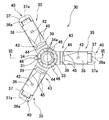
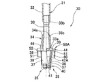
図1、図2に示すように、注出容器10は、シャンプーやリンスなどの液状の内容物を収容する容器本体11と、この容器本体11の口部13aに着脱自在に取り付けられた注出ポンプ20と、注出ポンプ20に着脱可能に取り付けられた支持装置30とを備えている。この注出容器10では、図1に仮想線で示すように、注出ポンプ20の操作部22を押し下げ操作することで、操作部22に設けられたノズル22aから内容物を注出でき、操作部22を押し下げたときに、注出ポンプ20に作用する下方への荷重を支持装置30で受け止めながら、内容物を注出できる。
Hereinafter, the present invention will be described based on illustrated embodiments.
As shown in FIGS. 1 and 2, the dispensing
<容器本体>
容器本体11としては、内容物を収容可能な本体部12と、注出ポンプ20を取り付け可能な口部13aとを備えたものであれば任意の構成のものを採用できる。特に、本発明では、注出ポンプ20を支持装置30で縦向姿勢に安定支持して、容器本体11を自立可能に構成でき、しかも注出ポンプ20の操作時における下方への力を支持装置30で受け止めて、注出ポンプ20の操作時における本体部12の変形を防止できるので、容器本体11の本体部12として、手で折り畳んだり潰したりして容易に減容化し得る極めて薄肉なものを採用できる。
<Container body>
As the container
具体的には、図1、図2に示す容器本体11のように、合成樹脂材料を含む軟質なフィルム材を用いて製作した本体部12と、本体部12にヒートシールなどにより一体的に固定した、射出成形品などからなる硬質の口部材13とを備え、口部材13に外部へ突出する口部13aを設け、本体部12の底面14を略平坦に構成したものを好適に採用できる。
Specifically, as in the container
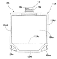
ただし、本体部12の形状、本体部12におけるフィルム材の接合構造、口部材13の形状などは、図1、図2に示す以外の周知の構成のものを採用できる。例えば、図18、図19に示すような本体部12Aを有する容器本体11Aを採用することもできる。具体的には、細長い長方形状の1枚のフィルム材を側面視3角形状に折り曲げて、前面部12Aaと後面部12Abと底面部12Acとを形成するとともに、平坦な底面部12Acをその前後方向の中央部において山折にした状態で、前面部12Aaと後面部12Abと底面部12Acとを重ね合わせて、前面部12Aaと後面部12Abの両側部を融着して側部シール部12Adを形成し、底面部12Acの前半部の両側部を前面部12Aaの両側部に融着するとともに、底面部12Acの後半部の両側部を後面部12Abの両側部に融着して、底面側部シール部12Aeを形成し、更に前面部12Aaの下端部と底面部12Acの前縁部とを融着するとともに、後面部12Abの下端部と底面部12Acの後縁部とを融着して、底面側部シール部12Aeに連なるように下端シール部12Afを形成し、前面部12Aaと後面部12Abの上端部の幅方向の中央部間に口部材13を融着固定してなる本体部12Aを採用することもできる。なお、下端シール部12Afは省略することも可能であるが、容器本体11Aの落下時におけるフィルム材の破れを効果的に防止するため設けることが好ましい。
However, as for the shape of the
なお、本体部を構成するフィルム材としては、容器本体に収容する内容物などに応じて、任意の素材、単層又は任意の積層構造のものを採用できる。また、同一構成のフィルム材で構成することもできるが、異なる構成のフィルム材を任意に組み合わせて構成することもできる。更にまた、本実施の形態では、本体部をフィルム材で構成してなる容器本体を採用したが、例えばブロー成形品からなる容器本体を採用することも可能である。 In addition, as a film material which comprises a main-body part, according to the content etc. which are accommodated in a container main body, the thing of arbitrary raw materials, a single layer, or arbitrary laminated structures is employable. Moreover, although it can also comprise with the film material of the same structure, it can also comprise combining the film material of a different structure arbitrarily. Furthermore, in the present embodiment, a container main body in which the main body portion is made of a film material is used. However, for example, a container main body made of a blow molded product can also be used.
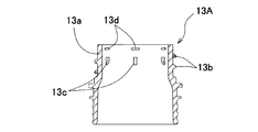
また、口部材13としては、図20〜図23に示すように、下面の両側部に外端側上がりの三角形状の傾斜面15を特徴部分として備えた口部材13Aを採用することもできる。このような構成の口部材13Aを用いると、注出容器10の落下時における、容器本体11の破れを一層効果的に防止できるので好ましい。
As shown in FIGS. 20 to 23, the
<注出ポンプ>
注出ポンプ20は、図1、図2に示すように、図示外のピストンが内装された筒状のシリンダケース21と、シリンダケース21から上方へ突出状に設けられて、シリンダケース21に上下移動自在に設けられた操作部22と、操作部22を上方へ常時付勢する図示外の復帰用のバネ部材と、口部13aに着脱自在に螺合されるキャップ部材23とを備えた、一般的な構成のものである。
<Pumping pump>
As shown in FIGS. 1 and 2, the dispensing
この注出ポンプ20は、シリンダケース21を口部13a内に挿入して、キャップ部材23を口部13aの螺子部13bに螺合することで、容器本体11に液密状に組み付けられる。そして、操作部22を下方へ押し操作することで、シリンダケース21の下端部に接続された後述する支持脚31からなる吸い上げ管を通じて、容器本体11内の内容物がシリンダケース21内に吸い上げられて、操作部22に設けられたノズル22aから外部へ吐出されるように構成されている。
The dispensing
ただし、注出ポンプ20としては、操作部22を押し操作することで内容物を吐出可能な注出ポンプ20以外に、例えばトリガーの回動操作により内容物を噴霧可能となしたトリガー式ポンプや、電動の注出ポンプを採用することもできる。
However, as the pumping
<支持装置>
次に、支持装置30の構成について図面を参照しながら説明する。
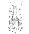
図1〜図16に示すように、支持装置30は、注出ポンプ20から下方へ延びる支持脚31と、支持脚31に上下動可能に外嵌されたスライド部材34と、支持脚31とスライド部材34とにわたって、支持脚31の周方向に間隔をあけて設けられた複数の脚部材35であって、上側リンク36及び下側リンク37と、スライド部材34よりも下側において支持脚31に対して下側リンク37を回動自在に連結する下側連結部38と、スライド部材34に対して上側リンク36を回動自在に連結する上側連結部39と、上側リンク36と下側リンク37とを回動自在に連結する中間連結部40とをそれぞれ有し、支持脚31に対するスライド部材34の上下方向への相対移動に伴って、支持脚31から側方へ延びる開脚姿勢と、下端側を上端側よりも支持脚31の中心側へ窄ませた閉脚姿勢とにわたって、開閉可能な複数の脚部材35と、複数の脚部材35に上側から着脱自在に外嵌されて、複数の脚部材35を閉脚姿勢に窄ませる、口部13aに対して一部又は全部が内嵌可能な絞りリング50とを備えている。
<Supporting device>
Next, the configuration of the
As shown in FIGS. 1 to 16, the
(支持脚)
支持脚31は、注出ポンプ20に対する内容物の吸い上げ管を兼ねており、シリンダケース21の下端部に設けられた取付部21aに着脱自在に取り付けられた略筒状の上側支持脚32と、上側支持脚32の下端部に内嵌接続された略筒状の下側支持脚33とを備えている。
(Support leg)
The
支持脚31は1つの筒状部材で構成することも可能であるが、本実施の形態のように上側支持脚32と下側支持脚33とに分割構成すると、長さの異なる支持脚を備えた支持装置を複数種類用意しないでも、上側支持脚32のみを長さの異なるものと交換することで、高さの異なる容器本体11に対しても支持装置30を容易に適用できるので好ましい。また、支持脚31を吸い上げ管として兼用したが、支持脚31とは別個に支持脚31内に吸い上げ管を設けて、その上端部を取付部21aに内嵌固定し、その下端部を容器本体11の底面14付近に開口させることもできる。ただし、支持脚31を注出ポンプ20のシリンダケース21との一体成形品で構成することも可能である。
The
下側支持脚33の下端部には1乃至複数の開口部33aが形成され、容器本体11内の内容物はこの開口部33aを通じて支持脚31内に導入されるように構成されている。
One or
下側支持脚33の高さ方向の途中部には筒状のスライド部材34が上下移動自在に外嵌され、スライド部材34の上端部には爪部34aが周方向に間隔をあけて複数個形成され、下側支持脚33の上部には爪部34aに係合してスライド部材34の上限位置を規制する環状の上限規制部33bが突出状に形成されている。下側支持脚33の下半部は上半部よりも大径に構成され、下側支持脚33の高さ方向の途中部には爪部34aに係合してスライド部材34の下限位置を規制する段差部からなる環状の下限規制部33cが形成され、スライド部材34は上限規制部33bと下限規制部33c間において上下移動自在に下側支持脚33に外嵌されている。
A
(脚部材)
脚部材35について説明すると、脚部材35は、平板状の上側リンク36及び下側リンク37と、下側支持脚33と下側リンク37とを回動自在に連結する下側連結部38と、スライド部材34と上側リンク36とを回動自在に連結する上側連結部39と、上側リンク36と下側リンク37とを回動自在に連結する中間連結部40とを備え、スライド部材34と下側支持脚33とにわたって周方向に間隔をあけて3個設けられている。3個の脚部材35は、下側支持脚33に対するスライド部材34の相対的な上下移動により開閉するように、スライド部材34の下端部と下側支持脚33の下端部とにわたって設けられている。これら3個の脚部材35は、スライド部材34が上限位置へ相対移動すると、図1、図3〜図6に図示の開脚姿勢に回動し、スライド部材34が下限位置へ相対移動すると、図2、図10、図11に図示の閉脚姿勢に回動するように構成されている。
(Leg member)
The
なお、本実施の形態では、3個の脚部材35を設けたが、脚部材35の個数は任意に設定可能である。ただし、脚部材35の個数が少なくなると、容器本体11の自立安定性が低下したり、ポンプ操作時に容器本体11が傾いてしまったりすることがあり、また多すぎると、製作コストが高くなるので、3個〜6個、好ましくは3個又は4個設けることが望ましい。
In the present embodiment, three
スライド部材34の下端部と上側リンク36の基端部間には、スライド部材34と上側リンク36とに一体成形された薄肉な弾性ヒンジを有する上側連結部39が設けられ、上側リンク36は上側連結部39を介してスライド部材34に回動自在に連結されている。
Between the lower end portion of the
下側支持脚33の下端部と下側リンク37の基端部間には、下側支持脚33と下側リンク37とに一体成形された薄肉な弾性ヒンジを有する下側連結部38が設けられ、下側リンク37は下側連結部38を介して下側支持脚33に回動自在に連結されている。
Between the lower end portion of the
下側リンク37の先端部には下側連結部38の回動中心と略平行に軸部37aが設けられ、上側リンク36の先端部には、下側リンク37の軸部37aに上側から着脱自在に嵌合する略U字状の軸受部36aが形成され、上側リンク36と下側リンク37とは、軸部37aと軸受部36aとを有する軸ヒンジからなる中間連結部40により回動自在に連結されている。
A
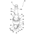
脚部材35は、絞りリング50を脚部材35から離脱させた自然状態において、弾性ヒンジを構成する素材の弾性により、支持脚31の中心線と平行な図9に図示の垂下姿勢よりも開脚した図12に図示の解除姿勢に開脚され、これにより支持装置30を注出ポンプ20とともに容器本体11に組み付けるときに、小さな操作力で脚部材35を容易に開脚姿勢に切り替えることが可能となる。ただし、支持装置30を構成する素材の弾性により、脚部材35を解除姿勢へ付勢させるための突部や舌部を形成することも可能である。
In the natural state in which the
下側リンク37の先端部には、解除姿勢において下側へ向けて突出する円弧面からなる開脚案内面41が設けられ、支持装置30を注出ポンプ20とともに容器本体11に組み付けるときに、この開脚案内面41が容器本体11の底面14に当接することで、脚部材35が開脚姿勢側へ案内されるように構成されている。
At the distal end of the
下側支持脚33とスライド部材34と脚部材35とは、合成樹脂材料単体または合成樹脂材料に必要な添加剤を添加した材料を用いて射出成形などにより成形されている。合成樹脂材料としては、機械的強度を有するものであれば任意の組成の合成樹脂材料を採用できるが、弾性ヒンジにおける繰り返しの折り曲げによく耐える合成樹脂材料、例えばポリプロピレンを好適に採用できる。
The
なお、本実施の形態では、中間連結部40を軸ヒンジで構成したが、上側連結部39と下側連結部38と中間連結部40の少なくとも1つを軸ヒンジで構成し、残りを弾性ヒンジで構成することもできる。ただし、上側連結部39と下側連結部38と中間連結部40の少なくとも1つは、弾性ヒンジで構成することが好ましい。また、中間連結部40を下側リンク37の先端部に設けたが、下側リンク37の長さ方向の途中部に設けることもできる。
In the present embodiment, the intermediate connecting
(絞りリングを用いた脚部材の開閉機構)
絞りリング50を用いた脚部材35の開閉機構について説明すると、絞りリング50は、図7に示すように、円筒状の胴体部51と、胴体部51の上部に外方へ突出状に形成された環状のリング部52とを備えている。絞りリング50は、複数の脚部材35の上部に着脱自在に外嵌されて、複数の脚部材35を、支持脚31の中心線と略平行な図9に図示の垂下姿勢よりも、さらに下端側を上端側よりも窄ませた、図10、図11に図示の閉脚姿勢に保持可能に構成されるとともに、注出ポンプ20及び支持装置30を容器本体11に組み付けた状態において口部13aに内嵌保持可能に構成されている。
(Leg member opening / closing mechanism using aperture ring)
The opening / closing mechanism of the
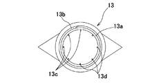
図7、図10、図11、図13〜図16に示すように、絞りリング50は、その全体が口部13aに内嵌可能な外径及び高さに構成され、口部13aの内面上部には複数の係止部13cが周方向に間隔をあけて内方へ向けて突出状に形成されている。絞りリング50は、リング部52の下面が係止部13cに当接することで、容器本体11内へ脱落しないように構成されている。係止部13cは、絞りリング50の下方への移動を係止した状態で、絞りリング50の上端部が口部13aから上方へ突出しない高さ位置に形成されている。
As shown in FIGS. 7, 10, 11, and 13 to 16, the
係止部13cよりも上側において口部13aの内面には、複数の保持部13dが周方向に間隔をあけて内側へ向けて突出状に形成され、図14に示すように、絞りリング50を口部13a内に内嵌装着した状態で、保持部13dがリング部52よりも上側に配置されるように構成されている。保持部13dの内側への突出高さは、係止部13cよりも低く設定され、一定の操作力で絞りリング50を操作することで、図15、図16に示すように、リング部52が保持部13dを乗り越えて、口部13aに対して絞りリング50を着脱できる高さに設定されている。絞りリング50を口部13aから抜き取るときの操作抵抗は、絞りリング50を脚部材35に外嵌させるときの操作抵抗よりも大きくなるように設定され、図2、図11、図16に示すように、支持装置30を容器本体11から抜き取るときに、絞りリング50により脚部材35が閉脚姿勢側へ操作されながら、絞りリング50が脚部材35の上部に外嵌されることで、脚部材35が閉脚姿勢に保持されてから、絞りリング50が口部13aから離脱するように構成されている。
A plurality of holding
係止部13c及び保持部13dは、本実施の形態では周方向に一定間隔おきに8個形成したが、係止部13c及び保持部13dの個数や周方向の形成位置は任意に設定可能であるし、口部13aの内周面に沿って環状に形成することも可能である。また、係止部13cに代えて、口部13aの上端に係合する鍔部を絞りリング50の上端部に外方へ突出状に形成することも可能である。
In the present embodiment, eight locking
図7、図9に示すように、絞りリング50の内径D1は、上側連結部39の外接円の直径D2よりも大きく、脚部材35を支持脚31の中心線と平行な垂下姿勢に回動させた状態における、脚部材35に対する絞りリング50の外嵌位置を構成する操作面40の最大外接円の直径D3よりも小さく設定され、絞りリング50を複数の脚部材35に外嵌させた状態で、絞りリング50により操作面40を内側へ押し操作して、脚部材35の下端側を上端側よりも支持脚31の中心側へ窄ませた閉脚姿勢に操作できるように構成されている。
As shown in FIGS. 7 and 9, the inner diameter D <b> 1 of the
上側リンク36の長さ方向の途中部には、脚部材35に対する絞りリング50の下限位置を規制する規制突部42が設けられ、絞りリング50を脚部材35に外嵌させて、脚部材35を閉脚姿勢に切り替えた状態で、絞りリング50の下端部が規制突部42に当接して、絞りリング50が脚部材35から下側へ脱落しないように構成されている。
In the middle of the
上側リンク36の回動中心側の外面には絞りリング50の下端部との接触により、複数の脚部材35を閉脚姿勢側へ操作する操作面43が設けられている。操作面43として、上側リンク36の回動中心側の外面には、回動中心側へ行くにしたがって上側リンク36を薄肉に構成する上部操作面44が形成され、上側リンク36の幅方向の両側の回動中心側には、上側リンク36の外面側の側縁を正面視略3角形状に面取りして、回動中心側へ行くにしたがって薄肉になるように構成した側部操作面45が形成されている。なお、上部操作面44及び側部操作面45は、平坦面で構成することも可能であるが、閉脚姿勢において絞りリング50の内面に沿うような円弧面に形成することも好ましい。ただし、操作面43としては、絞りリング50が外嵌されることで脚部材35を閉脚姿勢に操作可能な構成のものであれば、任意の構成のものを採用できる。
An
スライド部材34の上部には誘導リブ46が周方向に間隔をあけて複数形成され、誘導リブ46は上側へ行くにしたがって突出高さが低くなるように、例えば側面視三角形状に形成されている。これにより、絞りリング50を脚部材35に外嵌させるときに、この誘導リブ46によりスライド部材34の中心線が絞りリング50の中心線と合致するように案内されて、絞りリング50の下端部が上側連結部39に引っ掛かることが防止される。
A plurality of
<使用方法>
この支持装置30を取り付けた注出ポンプ20を容器本体11に組み付ける際には、図11に示すように、絞りリング50を脚部材35に外嵌させて、複数の脚部材35を閉脚姿勢に保持した状態で、該脚部材35をその先端側から容器本体11の口部13aに挿入し、支持装置30を注出ポンプ20とともに容器本体11に組み付けることになる。このとき、絞りリング50は、図15に示すように、その下端部が口部13aの上端部又は保持部13dに当接して脚部材35から抜き取られ、上側支持脚32に遊嵌状に外嵌される。そして、口部13aの外周面に形成されている螺子部13bに、注出ポンプ20のキャップ部材23を螺合させて、口部13aに対して注出ポンプ20を固定するときに、絞りリング50がキャップ部材23内に設けられたパッキン24で下方へ押し下げられて、図14に示すように、リング部52が保持部13dを乗り越えて、保持部13dと係止部13b間に保持されることで、絞りリング50が、容器本体11内に脱落しないように、口部13a内に保持される。また、図14に示すように、キャップ部材23を螺子部13bに締め付けることで、パッキン24が口部13aの上端部に圧接されて、注出ポンプ20が容器本体11に液密状に組み付けられる。一方、絞りリング50が抜き取られた脚部材35は、図13に示すように、鉛直方向の垂下姿勢よりも開脚した解除姿勢に素材の弾性により開脚し、図13に二点鎖線で示すように、下側リンク37の下端部の開脚案内面41が容器本体11の底面14に当接することで、図13に一点鎖線で示すように、開脚案内面41が底面14に沿って外方側へ移動することで開脚姿勢に開脚される。こうして、脚部材35を開脚姿勢に切り替えた状態で、図1に示すように、注出ポンプ20の操作部22を下方へ押し操作して、内容物を注出することになる。
<How to use>
When assembling the dispensing
一方、内容物を使い切るなどして、容器本体11を詰め替え用の容器本体11に交換する際には、キャップ部材23を緩めて、注出ポンプ20とともに支持装置30を容器本体11から抜き取ることになる。このとき、脚部材35は、開脚姿勢よりも閉脚した図13に図示の解除姿勢に素材の弾性で復帰する。そして、図16に示すように、口部13a内に保持された絞りリング50の下端部に、誘導リブ46が当接して、支持装置30の中心が絞りリンク50の中心側へ案内され、その後、絞りリング50が上部操作面44及び側部操作面45に順次外嵌されることで、絞りリング50により上部操作面44及び側部操作面45が絞りリング50の中央部側へ押し操作され、3個の脚部材35が、その下端側を窄ませた閉脚姿勢側へ操作されながら、図11に示すように、絞りリング50の下端部が規制突部42に当接するまで、絞りリング50が3個の脚部材35の上部に外嵌され、絞りリング50により3個の脚部材35が閉脚姿勢に保持される。このとき、絞りリング50を口部13aから抜き取るときの操作抵抗が、絞りリング50を脚部材35に外嵌させるときの操作抵抗よりも大きく設定されているので、絞りリング50は口部13a内に保持された状態に維持され、支持装置30を注出ポンプ20とともに容器本体11から抜き取るときの操作に連動して、口部13a内に保持されていた絞りリング50が自動的に脚部材35に嵌合され、脚部材35が閉脚姿勢に切り替えられることになる。こうして、脚部材35を絞りリング50により閉脚姿勢に切り替えた状態で、更に注出ポンプ20とともに支持装置30を引き抜き方向へ操作することで、絞りリング50のリング部52が保持部13を乗り越えて、絞りリング50が口部13aから離脱し、注出ポンプ20及び支持装置30を容器本体11から抜き取ることができる。そして、抜き取った注出ポンプ20及び支持装置30を詰め替え用の容器本体11に組み付ける際には、絞りリング50により脚部材35が閉脚姿勢に保持されているので、これをそのまま、前記と同様にして容器本体11に組み付けることになる。
On the other hand, when the container
この支持装置30では、これを注出ポンプ20とともに容器本体11に組み付けた状態で、複数の脚部材35が開脚姿勢に開脚されるので、脚部材35を構成する上側リンク36及び下側リンク37の強度剛性を高めることで、支持装置30による注出ポンプ20の支持強度を高めて、注出ポンプ20を操作して内容物を注出するときの、注出ポンプ20の安定性を向上できる。また、絞りリング50を脚部材35に外嵌させて、複数の脚部材35を閉脚姿勢に保持した状態において、脚部材35の下端側が上端側よりも支持脚31の中心側へ窄んだ状態となる。このため、支持装置30を容器本体11から抜き取るときに、脚部材35に内容物が付着していたとしても、該内容物は隣接する脚部材35間に保持されて、脚部材35の下端部から垂れ落ちることが防止される。また、閉脚姿勢において、複数の脚部材35の下端部の外接円が、特許文献3記載の支持装置のように、脚部材を垂下姿勢に保持する場合と比較して小さくなるので、その分、口部13aに対する脚部材35の挿入性を高めて、支持装置30を容器本体11に対して円滑に挿入できる。
In the
また、支持装置30を注出ポンプ20とともに容器本体11に組み付けた状態で、絞りリング50が保持部13dにより口部13aに保持されるので、支持装置30を注出ポンプ20とともに容器本体11から抜き取るときの操作に連動して、保持部13dに保持されていた絞りリング50を自動的に脚部材35に嵌合させて、脚部材35を閉脚姿勢に切り替えることができる。したがって、絞りリング50に手を触れることなく、脚部材35を閉脚姿勢に切り替えることが可能となり、内容物が付着した絞りリング50で手を汚すこともない。
Further, in the state where the
更に、上側リンク36とスライド部材34とを合成樹脂材料の一体成形品で構成し、下側リンク37と支持脚31とを合成樹脂材料の一体成形品で構成しているので、支持装置30を無理なく成形することが可能となるとともに、上側リンク36及び下側リンク37を別部材で構成する場合と比較して、支持装置30の部品点数を少なくできる。また、両部材を組み合わせた状態で、軸受部36aを上側から軸部37aに嵌合させることで、支持装置30を容易に組み立てることができるので好ましい。更に、弾性ヒンジからなる上側連結部39及び下側連結部38における素材の弾性により、絞りリング50を脚部材35から抜き取って脚部材35を開脚させるときに、脚部材35が解除姿勢側へ回動するので、脚部材35を開脚姿勢へ容易に操作することが可能となる。
Furthermore, since the
なお、広口な口部を有する容器本体に本発明を適用するため、絞りリング50として、図17に示すように、絞りリング50よりも大きな直径の絞りリング50Aを用いる場合には、側部操作面45に代えて、各脚部材35の上側リング36の上部に、外方へ突出する1乃至複数枚の操作リブ60を形成し、閉脚姿勢において該操作リブ60の上部に、上側へ行くにしたがってスライド部材34の中心側へ傾斜した操作面61を形成することもできる。また、この場合には、図17に示すように、規制突部42に代えて、操作リブ60の下端部に外方へ突出する規制突部42Aを形成することもできる。このように構成すると、操作リブ60の外方への突出高さを絞りリング50Aの内径に応じて調整することで、上部リンク36の厚さを変更したりすることなく、各種口部の容器に対して本発明を容易に適用できるので好ましい。
In order to apply the present invention to a container body having a wide mouth portion, as shown in FIG. 17, when using a
以上、本発明の実施形態について説明したが、本発明は前述した実施形態に何ら限定されるものではなく、本発明の要旨を逸脱しない範囲においてその構成を変更し得ることは勿論である。 The embodiment of the present invention has been described above. However, the present invention is not limited to the above-described embodiment, and it goes without saying that the configuration can be changed without departing from the gist of the present invention.
10 注出容器
11 容器本体
12 本体部
13 口部材
13a 口部
13b 螺子部
13c 係止部
13d 保持部
14 底面
20 注出ポンプ
21 シリンダケース
21a 取付部
22 操作部
22a ノズル
23 キャップ部材
24 パッキン
30 支持装置
31 支持脚
32 上側支持脚
33 下側支持脚
33a 開口部
33b 上限規制部
33c 下限規制部
34 スライド部材
34a 爪部
35 脚部材
36 上側リンク
36a 軸受部
37 下側リンク
37a 軸部
38 下側連結部
39 上側連結部
40 中間連結部
41 開脚案内面
42 規制突部
43 操作面
44 上部操作面
45 側部操作面
46 誘導リブ
50 絞りリング
51 胴体部
52 リング部
11A 容器本体
12A 本体部
12Aa 前面部
12Ab 後面部
12Ac 底面部
12Ad 側部シール部
12Ae 底面側部シール部
12Af 下端シール部
13A 口部材
15 傾斜面
50A 絞りリング
42A 規制突部
60 操作リブ
61 操作面
DESCRIPTION OF
Claims (10)
前記支持装置は、
前記注出ポンプから下方へ延びる支持脚と、
前記支持脚に上下動可能に外嵌されたスライド部材と、
前記支持脚とスライド部材とにわたって、前記支持脚の周方向に間隔をあけて設けられた複数の脚部材であって、上側リンク及び下側リンクと、前記スライド部材よりも下側において、前記支持脚に対して前記下側リンクを回動自在に連結する下側連結部と、前記スライド部材に対して上側リンクを回動自在に連結する上側連結部と、前記上側リンクと下側リンクとを回動自在に連結する中間連結部とをそれぞれ有し、前記支持脚に対するスライド部材の上下方向への相対移動に伴って、前記支持脚から側方へ延びる開脚姿勢と、下端側を上端側よりも支持脚の中心側へ窄ませた閉脚姿勢とにわたって、開閉可能な複数の脚部材と、
前記複数の脚部材に上側から着脱自在に外嵌されて、前記複数の脚部材を閉脚姿勢に窄ませる、前記口部に内嵌可能な絞りリングと、
を備えた、
ことを特徴とする注出ポンプの支持装置。 A support device for a pour pump that supports a pour pump that is detachably attached to the mouth of the container body,
The support device is
A support leg extending downward from the dispensing pump;
A slide member externally fitted to the support leg so as to be movable up and down;
A plurality of leg members provided at intervals in the circumferential direction of the support leg across the support leg and the slide member, wherein the support is provided below the upper link and the lower link, and below the slide member. A lower connecting portion that rotatably connects the lower link to the leg, an upper connecting portion that rotatably connects the upper link to the slide member, and the upper and lower links. An intermediate connecting portion that is rotatably connected to each other, and an open leg posture that extends laterally from the support leg as the slide member moves relative to the support leg in the vertical direction; A plurality of leg members that can be opened and closed over a closed leg posture narrowed to the center side of the support leg,
A squeezing ring that is detachably fitted to the plurality of leg members from above to squeeze the plurality of leg members into a closed leg posture, and can be fitted into the mouth.
With
A pumping pump support device characterized by that.
Priority Applications (1)
| Application Number | Priority Date | Filing Date | Title |
|---|---|---|---|
| JP2016157886A JP2018024456A (en) | 2016-08-10 | 2016-08-10 | Support device of pour-out pump |
Applications Claiming Priority (1)
| Application Number | Priority Date | Filing Date | Title |
|---|---|---|---|
| JP2016157886A JP2018024456A (en) | 2016-08-10 | 2016-08-10 | Support device of pour-out pump |
Publications (1)
| Publication Number | Publication Date |
|---|---|
| JP2018024456A true JP2018024456A (en) | 2018-02-15 |
Family
ID=61194796
Family Applications (1)
| Application Number | Title | Priority Date | Filing Date |
|---|---|---|---|
| JP2016157886A Pending JP2018024456A (en) | 2016-08-10 | 2016-08-10 | Support device of pour-out pump |
Country Status (1)
| Country | Link |
|---|---|
| JP (1) | JP2018024456A (en) |
Cited By (1)
| Publication number | Priority date | Publication date | Assignee | Title |
|---|---|---|---|---|
| JP2020019542A (en) * | 2018-08-01 | 2020-02-06 | 凸版印刷株式会社 | Spouting packaging bag |
Citations (6)
| Publication number | Priority date | Publication date | Assignee | Title |
|---|---|---|---|---|
| JP2001231803A (en) * | 2000-02-24 | 2001-08-28 | Medicos Hirata:Kk | Jig for stoma |
| WO2003051153A2 (en) * | 2001-12-17 | 2003-06-26 | Jung-Min Lee | Self-standing pouch container integrated with pump dispenser |
| JP2012184033A (en) * | 2011-02-17 | 2012-09-27 | Taisei Kako Co Ltd | Container with pump, and pouring pump used for the same |
| JP2014069818A (en) * | 2012-09-28 | 2014-04-21 | Tobi Co Ltd | Extraction device |
| JP2015199541A (en) * | 2014-03-31 | 2015-11-12 | シロウマサイエンス株式会社 | Discharge pump support device, and discharge pump and discharge vessel using same |
| JP2015199542A (en) * | 2014-03-31 | 2015-11-12 | シロウマサイエンス株式会社 | Discharge pump support device, and discharge pump and discharge vessel using same |
-
2016
- 2016-08-10 JP JP2016157886A patent/JP2018024456A/en active Pending
Patent Citations (7)
| Publication number | Priority date | Publication date | Assignee | Title |
|---|---|---|---|---|
| JP2001231803A (en) * | 2000-02-24 | 2001-08-28 | Medicos Hirata:Kk | Jig for stoma |
| WO2003051153A2 (en) * | 2001-12-17 | 2003-06-26 | Jung-Min Lee | Self-standing pouch container integrated with pump dispenser |
| JP2012184033A (en) * | 2011-02-17 | 2012-09-27 | Taisei Kako Co Ltd | Container with pump, and pouring pump used for the same |
| JP2014097848A (en) * | 2011-02-17 | 2014-05-29 | Nihon Yamamura Glass Co Ltd | Pump-equipped container and injection pump used in the same |
| JP2014069818A (en) * | 2012-09-28 | 2014-04-21 | Tobi Co Ltd | Extraction device |
| JP2015199541A (en) * | 2014-03-31 | 2015-11-12 | シロウマサイエンス株式会社 | Discharge pump support device, and discharge pump and discharge vessel using same |
| JP2015199542A (en) * | 2014-03-31 | 2015-11-12 | シロウマサイエンス株式会社 | Discharge pump support device, and discharge pump and discharge vessel using same |
Cited By (1)
| Publication number | Priority date | Publication date | Assignee | Title |
|---|---|---|---|---|
| JP2020019542A (en) * | 2018-08-01 | 2020-02-06 | 凸版印刷株式会社 | Spouting packaging bag |
Similar Documents
| Publication | Publication Date | Title |
|---|---|---|
| US8141731B2 (en) | Closure with lid and slidable latch system | |
| EP1444049B1 (en) | Foam dispenser and storage holder therefor | |
| WO2011099309A1 (en) | Fluid storage container and lid thereof | |
| JP4944960B2 (en) | Flexible down tube and its use | |
| TWI500566B (en) | Squeeze the cover of the container | |
| JP2018024456A (en) | Support device of pour-out pump | |
| JP4250037B2 (en) | Cartridge type dispensing container | |
| JP2011136706A (en) | Refilling container | |
| JP5977642B2 (en) | Refill container stopper | |
| JP6466759B2 (en) | Dispensing pump support device and dispensing pump and dispensing container using the same | |
| ITRM930490A1 (en) | CONTAINER DISPENSER OF VISCOUS FLUID PRODUCT WITH MANUAL PUSH FROM BELOW, PARTICULARLY FOR COSMETIC, PHARMACEUTICAL USE. | |
| JP7175493B2 (en) | Fluid discharge container | |
| JP5708785B2 (en) | Container with pump and pouring pump used therefor | |
| WO2014157693A1 (en) | Spouting pump and pump-equipped container provided with same, container body used in spouting pump, and port member for container body | |
| JP2011136699A (en) | Fixing device of pump container | |
| JP5714223B2 (en) | Container with pump | |
| JP4018017B2 (en) | Liquid ejector | |
| JP4428575B2 (en) | Container with pump | |
| JP2006341861A (en) | Container | |
| JP4950117B2 (en) | Refill aid and pour container equipped with this | |
| WO2012150678A1 (en) | Inverted cap for container for highly viscous liquid | |
| JP2012106749A (en) | Content filling mechanism | |
| JP6532383B2 (en) | Trigger type spout container | |
| JP2023534440A (en) | dispensable food container | |
| JP2021084647A (en) | Container body, composite container body, and airless pump mounted to the container body |
Legal Events
| Date | Code | Title | Description |
|---|---|---|---|
| A621 | Written request for application examination |
Free format text: JAPANESE INTERMEDIATE CODE: A621 Effective date: 20190617 |
|
| A977 | Report on retrieval |
Free format text: JAPANESE INTERMEDIATE CODE: A971007 Effective date: 20200310 |
|
| A131 | Notification of reasons for refusal |
Free format text: JAPANESE INTERMEDIATE CODE: A131 Effective date: 20200317 |
|
| A02 | Decision of refusal |
Free format text: JAPANESE INTERMEDIATE CODE: A02 Effective date: 20201006 |