JP4427876B2 - Semiconductor angular velocity sensor - Google Patents
Semiconductor angular velocity sensor Download PDFInfo
- Publication number
- JP4427876B2 JP4427876B2 JP2000220922A JP2000220922A JP4427876B2 JP 4427876 B2 JP4427876 B2 JP 4427876B2 JP 2000220922 A JP2000220922 A JP 2000220922A JP 2000220922 A JP2000220922 A JP 2000220922A JP 4427876 B2 JP4427876 B2 JP 4427876B2
- Authority
- JP
- Japan
- Prior art keywords
- angular velocity
- portions
- beams
- vibrator
- velocity sensor
- Prior art date
- Legal status (The legal status is an assumption and is not a legal conclusion. Google has not performed a legal analysis and makes no representation as to the accuracy of the status listed.)
- Expired - Fee Related
Links
Images


Classifications
-
- G—PHYSICS
- G01—MEASURING; TESTING
- G01P—MEASURING LINEAR OR ANGULAR SPEED, ACCELERATION, DECELERATION, OR SHOCK; INDICATING PRESENCE, ABSENCE, OR DIRECTION, OF MOVEMENT
- G01P15/00—Measuring acceleration; Measuring deceleration; Measuring shock, i.e. sudden change of acceleration
- G01P15/02—Measuring acceleration; Measuring deceleration; Measuring shock, i.e. sudden change of acceleration by making use of inertia forces using solid seismic masses
- G01P15/08—Measuring acceleration; Measuring deceleration; Measuring shock, i.e. sudden change of acceleration by making use of inertia forces using solid seismic masses with conversion into electric or magnetic values
- G01P2015/0805—Measuring acceleration; Measuring deceleration; Measuring shock, i.e. sudden change of acceleration by making use of inertia forces using solid seismic masses with conversion into electric or magnetic values being provided with a particular type of spring-mass-system for defining the displacement of a seismic mass due to an external acceleration
- G01P2015/0808—Measuring acceleration; Measuring deceleration; Measuring shock, i.e. sudden change of acceleration by making use of inertia forces using solid seismic masses with conversion into electric or magnetic values being provided with a particular type of spring-mass-system for defining the displacement of a seismic mass due to an external acceleration for defining in-plane movement of the mass, i.e. movement of the mass in the plane of the substrate
- G01P2015/0811—Measuring acceleration; Measuring deceleration; Measuring shock, i.e. sudden change of acceleration by making use of inertia forces using solid seismic masses with conversion into electric or magnetic values being provided with a particular type of spring-mass-system for defining the displacement of a seismic mass due to an external acceleration for defining in-plane movement of the mass, i.e. movement of the mass in the plane of the substrate for one single degree of freedom of movement of the mass
- G01P2015/0814—Measuring acceleration; Measuring deceleration; Measuring shock, i.e. sudden change of acceleration by making use of inertia forces using solid seismic masses with conversion into electric or magnetic values being provided with a particular type of spring-mass-system for defining the displacement of a seismic mass due to an external acceleration for defining in-plane movement of the mass, i.e. movement of the mass in the plane of the substrate for one single degree of freedom of movement of the mass for translational movement of the mass, e.g. shuttle type
Description
【0001】
【発明の属する技術分野】
本発明は、車両、飛行機、ロボット等の運動体の運動状態を測定するのに用いられる、加速度センサや角速度センサ等の半導体よりなる振動子を用いた半導体力学量センサに関する。
【0002】
【従来の技術】
一般に、この種の半導体力学量センサは、シリコン基板等の半導体基板をエッチング等のマイクロマシン加工技術を用いて加工することにより形成され、基部と、所定方向に振動する振動子と、該振動子及び該基部を連結する複数個の梁部とを備え、該振動子の振動に基づいて力学量(角速度、加速度等)を検出するようにしている。
【0003】
例えば、角速度センサにあっては、振動子を所定方向に駆動振動させ、角速度が印加されたとき、コリオリ力によって駆動振動の方向及び角速度の回転軸に直交する方向へ発生する振動(検出振動)に基づいて、当該角速度を検出する。また、加速度センサにあっては、振動子に加速度が印加されたときに発生する所定方向への振動(検出振動)に基づいて、当該加速度を検出する。
【0004】
【発明が解決しようとする課題】
しかしながら、従来の半導体力学量センサにおいては、センサの加工誤差(例えばエッチングの際の加工誤差)が生じることは避けがたい。この加工誤差により、振動子には、上記の駆動振動や検出振動といった正規の振動に対して、当該正規の振動以外の不要振動が発生するため、これが測定誤差の原因となっている。
【0005】
本発明者等は、この不要振動は、振動子と基部とを連結する複数個の梁部に原因があるのではないかと考えた。つまり、従来の半導体力学量センサにおいては、例えば特開平6−123631号公報に記載されているように、複数個の梁部の各々が1本の棒状梁よりなる構成であるため、回転剛性が弱く、振動子の振動中に各梁にねじれ等が発生しやすく、そのねじれ等が不要振動を引き起こすと考えられる。
【0006】
本発明は上記事情に鑑み、半導体力学量センサにおいて、振動子の振動を阻害することなく回転剛性を高めた梁部の構成を実現することを目的とする。
【0007】
【課題を解決するための手段】
上記目的を達成するため、請求項1記載の発明では、半導体基板を加工することにより形成され、基部(10)と、所定方向に振動する振動子(20、30)と、この振動子及び該基部を連結する複数個の梁部(21、31)とを備える半導体角速度センサにおいて、該複数個の梁部のそれぞれを、平行に離間して配置された一対の梁(22、23、32、33)と、これら一対の梁を連結する連結部(24、34)とから構成し、
上記一対の梁を、コの字形状をなす第1の梁(22、32)と、この第1の梁の外周側にて該第1の梁に対して相似形に配置されたコの字形状をなす第2の梁(23、33)とから構成するとともに、これらコの字形状をなす第1及び第2の梁における互いに平行な一対の平行棒部(22a、23a、32a、33a)を該振動子の振動方向にたわむようにし、該平行棒部の一端を接続する接続棒部(22b、23b、32b、33b)同士を連結部(24、34)にて連結させたことを特徴としている。
【0008】
回転剛性を高めるだけならば、梁部を単に太いものとすればよいが、それだけでは、センサとして必要な変位をとることが困難となり振動子の振動を阻害してしまう。本発明によれば、梁部の構成を、平行に離間配置して連結された一対の梁構成としているから、振動子の振動を阻害することなく回転剛性を高めた梁部の構成を実現することができる。
【0010】
また、本発明によれば、相似形状に平行配置されたコの字形状をなす第1及び第2の梁において、振動子の振動方向に撓む部分である平行棒部で連結せず、振動子の振動に関与しない接続棒部同士にて連結しているから、より効果的に振動子の振動を阻害しない梁部の構成を実現できる。
請求項2記載の発明では、連結部(24、34)は、振動子(20、30)が振動する前記所定方向と直交する方向に延びた形状であることを特徴としている。
【0011】
また、請求項3記載の発明によれば、第1の梁(22、32)と第2の梁(23、33)との間隔において、接続棒部(22b、23b、32b、33b)同士の間隔を平行棒部(22a、23a、32a、33a)同士の間隔よりも大きくしている。第1の梁の平行棒部と第2の梁の平行棒部とは長さが異なるため変位に差が生じるが、本発明によれば連結部を充分に長くできるから、そのような変位の相違を吸収しやすくでき、より効果的に振動を阻害しないようにできる。
【0012】
また、請求項4記載の発明によれば、連結部(24、34)を、一対の梁部(22、23、32、33)と略同一の幅を有する梁形状としたことを特徴としている。連結部が太すぎると連結部による一対の梁部の固定が強すぎて、振動を阻害する恐れがあり、また、センサの加工上、連結部が細すぎると加工しにくくなるため、連結部を、一対の梁部と略同一の幅とすることが好ましい。
【0013】
また、請求項5記載の発明によれば、接続棒部(22b、23b、32b、33b)同士の間隔(W1)と平行棒部(22a、23a、32a、33a)同士の間隔(W2)との比(W1/W2)が5以上であることを特徴としている。これは、接続棒部同士の間隔即ち連結部(24、34)の長さについて、検討した結果、得られたもので、上記比(W1/W2)が5以上であれば、不要振動の低減効果を最大限に発揮させることができる。
【0014】
また、請求項6記載の発明では、半導体基板を加工することにより形成され、基部(10)と、所定方向に振動する振動子(20、30)と、この振動子及び基部を連結する複数個の梁部(21、31)とを備え、該振動子の振動に基づいて角速度を検出するようにした振動型の半導体角速度センサにおいて、該複数個の梁部が、互いに平行に配置された第1、第2の梁(22、23、32、33)から構成され、この第1、第2の梁は折り返し部(22b、23b、32b、33b)を備え、この折り返し部において、第1、第2の梁を連結する連結棒(24、34)を有し、この連結棒により第1の梁と第2の梁との間に2つのL字状の空間が形成され、また、L字状の空間が該連結棒に対して対称的に配置されるものであり、
第1、第2の梁(22、23、32、33)は、折り返し部を除く部分(22a、23a、32a、33a)が前記所定方向にたわむようになっていることを特徴としている。
【0015】
本発明のような梁部の構成を採用することにより、振動子の振動を阻害することなく回転剛性を高めた梁部の構成を実現することができ、不要振動を大幅に低減することができる。
【0016】
さらに、不要振動を低減するために、請求項6記載の半導体力学量センサについて、本発明者等が検討した結果によれば、請求項7記載の発明のように、折り返し部(22b、23b、32b、33b)において、第1、第2の梁(22、23、32、33)のそれぞれの梁幅をほぼ同じとすることが好ましい。
【0017】
また、請求項8記載の発明のように、連結棒(24、34)を、第1の梁(22、32)から第2の梁(23、33)に渡ってほぼ同じ幅とすることが好ましい。更には、請求項9記載の発明のように、請求項7の発明と請求項8の発明とを組み合わせたものとすることが好ましい。
【0018】
連結部や梁部の折り返し部に肉厚の部分が存在すると、連結部や折り返し部の質量が増加し、この影響が不要振動に影響すると考えられるが、その点、上記請求項7〜請求項9の発明によれば、そのような肉厚部を低減することができるため、不要振動が低減されると考えられる。
【0019】
また、請求項10記載の発明では、連結棒(24、34)は、前記所定方向と直交する方向に延びていることを特徴としている。
また、請求項11に記載の発明では、半導体基板を加工することにより形成され、基部(10)と、所定方向に振動する振動子(20、30)と、この振動子及び基部を連結する複数個の梁部(21、31)とを備え、振動子の振動に基づいて角速度を検出するようにした振動型の半導体角速度センサにおいて、
複数個の梁部は、それぞれが、平行に離間して配置された一対の梁(22、23、32、33)と、これら一対の梁を連結する連結部(24、34)とから構成されており、
一対の梁は、それぞれがコの字型に屈曲した屈曲部(22b、23b、32b、33b)を有する形状であって、屈曲部を除く部分(22a、23a、32a、33a)が前記所定方向にたわむようになっており、
連結部は、一対の梁における屈曲部同士を連結していることを特徴としている。
また、請求項12に記載の発明では、連結部(24、34)は、前記所定方向と直交する方向に延びた形状であることを特徴としている。
なお、上記各手段の括弧内の符号は、後述する実施形態に記載の具体的手段との対応関係を示すものである。
【0020】
【発明の実施の形態】
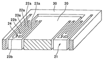
以下、本発明を図に示す実施形態について説明する。図1は、本発明の半導体力学量センサとしての角速度センサ100の一実施形態を示す平面図であり、図2は、図1中のA−A断面を含む一部断面斜視図である。角速度センサ100は、シリコン基板等の半導体基板にエッチング加工を施すことにより溝を形成し、当該基板を矩形枠状の基部10と、この基部10における枠内に位置して可動する可動部とに区画している。
【0021】
可動部は、図1に示す様に、略矩形状の駆動用振動子20と、駆動用振動子20を取り囲む矩形枠状の検出用振動子30と、駆動用振動子20及び検出用振動子30を連結する複数個(図示例では4個)の駆動用梁部21と、検出用振動子30及びその外周の基部10を連結する複数個(図示例では4個)の検出用梁部31と、を備えている。
【0022】
ここで、本実施形態では、駆動用振動子20及び検出用振動子30は本発明でいう振動子である。駆動用振動子20は、駆動用梁部21を介して検出用振動子30と一体化されており、さらに言うならば、駆動用振動子20は検出用振動子30及び検出用梁部31を介在させてはいるが、駆動用梁部21を介して基部10に連結されている。よって、駆動用梁部21及び検出用梁部31は共に、本発明でいう梁部に相当するものである。
【0023】
各々の駆動用梁部21は、コの字形状をなす第1の梁22と、この第1の梁22の外周側にて第1の梁22に対して相似形に配置されたコの字形状をなす第2の梁23とよりなる一対の梁を備えている。そして、これら一対の梁22、23は、平行に離間して配置されており、一対の梁22、23の一端側が駆動用振動子20に接続され、他端側が検出用振動子30における枠内周面に接続されている。
【0024】
また、駆動用梁部21の第1の梁22及び第2の梁23においては、上記コの字形状における互いに平行な一対の平行棒部22a及び23aが、その長手方向と直交する方向にたわむようになっているため、駆動用振動子20は図1中の矢印X方向に振動可能となっている。そして、第1の梁22及び第2の梁23のうち平行棒部22a、23aの一端を接続する接続棒部22b、23b同士が、梁形状の連結部24により連結されている。
【0025】
一方、各々の検出用梁部31は、コの字形状をなす第1の梁32と、この第1の梁32の外周側にて第1の梁32に対して相似形に配置されたコの字形状をなす第2の梁33とよりなる一対の梁を備えている。そして、これら一対の梁32、33は、平行に離間して配置されており、一対の梁32、33の一端側が検出用振動子30に接続され、他端側が基部10における枠内周面から突出した突出部に接続されている。
【0026】
また、検出用梁部31の第1の梁32及び第2の梁33においては、上記コの字形状における互いに平行な一対の平行棒部32a及び33aが、その長手方向と直交する方向にたわむようになっているため、検出用振動子30は、上記基板平面内にて駆動用振動子20の振動方向と略直交する方向(図1中の矢印Y方向)に振動可能となっている。そして、第1の梁32及び第2の梁33のうち平行棒部32a、33aの一端を接続する接続棒部32b、33b同士が、梁形状の連結部34により連結されている。
【0027】
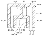
また、図3は駆動用梁部21及び検出用梁部31の寸法説明図である。両梁部21、31のいずれにおいても、第1の梁22、32と第2の梁23、33との間隔において、接続棒部22b、23b、32b、33b同士の間隔W1は平行棒部22a、23a、32a、33a同士の間隔W2よりも大きくなっている。また、梁形状をなす連結部24、34の幅は上記一対の梁と略同一の幅を有することが好ましい。例えば、上記間隔W1は50μm、上記間隔W2は10μm、また、各梁22、23、32、33及び連結部24、34の幅W3は10μmとできる。
【0028】
また、検出用振動子30の外周部には、この外周部と対向する基部10の内周部に向かって突出する櫛歯状の突起部35が形成されており、この突起部35とかみ合うように当該基部10の内周部からも櫛歯状の突起部11が形成されており、両方の突起部11、35により、本センサ100の検出電極部が構成されている。
【0029】
かかる構成を有する角速度センサ100の作動について述べる。まず、図示しないが電磁駆動もしくは容量駆動等により、駆動用振動子20を図1に示す矢印X方向に振動(駆動振動)させる。この駆動振動のもと、図1に示す様に、紙面垂直方向の軸周りに角速度Ωがセンサ100に印加されると、駆動用振動子20に駆動振動方向と直交する矢印Y方向にコリオリ力が発生する。
【0030】
このコリオリ力は駆動用梁部21から検出用振動子30に伝わり、検出用振動子30と駆動用振動子20とが図1に示す矢印Y方向に一体に振動(検出振動)する。そして、この検出振動により、上記両突起部11、35間の距離が変化する。この距離変化を基部10に形成された図示しない配線部等を介して、当該両突起部11、35間の容量変化として検出することにより、上記角速度Ωが検出されるのである。
【0031】
ところで、本実施形態によれば、各梁部21、31の構成を、平行に離間配置して連結された一対の梁構成としているから、各振動子20、30の振動を阻害することなく回転剛性を高めた梁部の構成を実現することができる。ちなみに、回転剛性を高めるだけならば、梁部を単に太いものとすればよいが、それだけでは、センサとして必要な変位をとることが困難となり、振動子の振動を阻害してしまう。
【0032】
また、本実施形態によれば、相似形状に平行配置されたコの字形状をなす第1及び第2の梁22、23、32、33において、各振動子20、30の振動方向に撓む部分である平行棒部22a、23a、32a、33aで連結せず、振動子の振動に関与しない接続棒部22b、23b、32b、33b同士にて連結しているから、より効果的に振動子20、30の振動を阻害しない梁部の構成を実現できる。
【0033】
本実施形態の梁部構成の具体的な作用を図4の作用説明図を用いて説明する。図4中の左右方向が振動子における狙いの振動方向である。従来のセンサにおいては、駆動用振動子20と検出用振動子30とを連結する梁部J1が1本のコの字形状のものであり、回転剛性が弱く、駆動用振動子20は振動狙いの振動方向よりも、やや斜め(図中では斜め上方)方向に振動してしまい、これが不要振動となる。
【0034】
一方、本実施形態の梁部構成では、回転剛性を高め、且つ、振動子の振動を阻害しないようにしているから、駆動用振動子20は狙いの方向に振動する。よって、本実施形態によれば、不要振動を低減できるため、角速度が0の状態でも出力が発生するオフセットを抑制し、測定精度の高い角速度センサを提供することができる。
【0035】
本実施形態の効果を、図5を用いて改めて説明する。図5(a)には、梁形状を4種類用意し、これらの梁による不要振動を角速度として算出したデータを示す。梁形状▲1▼はコンベンショナルな梁である。梁形状▲2▼は”A Precision Yaw Rate Sensor in Silicon Micromachining”(TRANSDUCERS’97 pp.847−850,1997IEEE)に掲載されたFig.8に類似した2重梁構造のものである。
【0036】
梁形状▲3▼と▲4▼は、本実施形態のものであり、連結部の長さを変えたものである。梁形状▲4▼の方が梁形状▲3▼よりも長くなっている。図5(a)から、コンベンショナルな梁形状▲1▼に比べ、梁形状▲2▼、▲3▼、▲4▼の方が不要振動を大きく低減できることがわかる。
【0037】
つまり、本実施形態では、各梁部21、31が、互いに平行に配置された第1の梁22、32、第2の梁23、33から構成され、この第1、第2の梁は折り返し部としての接続棒部22b、23b、32b、33bを備え、この折り返し部において、第1、第2の梁を連結する連結棒としての連結部24、34を有し、この連結棒により第1の梁と第2の梁との間に2つのL字状の空間が形成され、また、L字状の空間が該連結棒に対して対称的に配置されているものとなっている。
【0038】
そして、このような梁部21、31の構成を採用することにより、振動子20、30の振動を阻害することなく回転剛性を高めた梁部の構成を実現することができ、図5(a)に示す様に、不要振動を大幅に低減することができる。
【0039】
また、図5(b)は、さらに、梁形状▲2▼、▲3▼、▲4▼による効果の違いをより厳密に見たものであり、梁形状▲2▼に比べ、連結部を有する梁形状▲3▼、▲4▼の方が不要振動を抑制する効果が大きく、さらに梁形状▲3▼に比べ、連結部の長い梁形状▲4▼の方が効果が大きい。
【0040】
さらに、本実施形態によれば、各梁部21、31における第1の梁22、32と第2の梁23、33との間隔において、接続棒部同士の間隔W1を平行棒部同士の間隔W2よりも大きくしているため、連結部24、34を充分に長くでき、結果的に、第1の梁の平行棒部と第2の梁の平行棒部とに生じる変位の相違を吸収しやすくでき、より効果的に振動を阻害しないようにできる。
【0041】
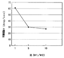
連結部の長さについて、さらに厳密に検討した結果を図6に示す。この図6は、連結部24、34の長さW1と平行棒部22a、23a、32a、33a同士の間隔(梁間隔)W2との比W1/W2に対する不要振動出力を調べたものである。長さW1は、上記図3に示した接続棒部22b、23b、32b、33b同士の間隔W1に相当するものである。
【0042】
W1とW2との比が1(W1/W2=1)に対して、W1とW2との比が5以上になると、その効果が大きいといえる。そして、比W1/W2が5あたりで効果は飽和しており、比W1/W2が5以上あれば十分と言える。つまり、接続棒部22b、23b、32b、33b同士の間隔W1と平行棒部22a、23a、32a、33a同士の間隔W2との比W1/W2が、5以上であることが好ましく、それにより、不要振動の低減効果が最大限に発揮される。
【0043】
また、連結部が太すぎると連結部による一対の梁部の固定が強すぎて、振動を阻害する恐れがあり、更に、センサの加工上、連結部が細すぎると加工しにくくなるため、連結部24、34の幅を、一対の梁部22、23、32、33と略同一の幅とすることが好ましい。
【0044】
図7には、連結部の形状による効果の違いを示す。図7の梁形状▲5▼、▲6▼は両方とも本実施形態のものである。梁形状▲5▼は、外側の梁と内側の梁とが連結部にて接続される領域(つまり、接続棒部)においても、同様の梁幅となっている(さらに、連結部も梁と同様の梁幅となっている)が、梁形状▲6▼は、外側の梁が連結部にて接続される領域(接続棒部)において、内側の梁よりもその幅が大きくなっているものである。
【0045】
この図7から、連結部(連結棒)24、34にて連結される領域(接続棒部、折り返し部)22b、23b、32b、33bにおいて、外側の梁(第2の梁)23、33と内側の梁(第1の梁)22、32との梁幅は同等であることが好ましいと言える。
【0046】
また、連結部(連結棒)24、34は、内側の梁(第1の梁)22、32に連結する部位から外側の梁(第2の梁)23、33に連結する部位に渡ってほぼ同じ幅であることが好ましいといえる。これは、連結部や梁部の折り返し部に肉厚の部分が存在すると、連結部や折り返し部の質量が増加し、この影響が不要振動に影響すると考えられるためである。
【0047】
ここで、本実施形態の具体的な効果を図8に示す。図8は、本角速度センサ100と従来の角速度センサとの梁部の加工誤差に対する不要振動振幅の度合を調べた一例である。本角速度センサ100においては、梁部の各寸法W1〜W3を、上記の図3を参照して述べた具体的寸法とした。また、従来のものにおいては、図4に示したような1本の梁よりなる梁部J1を持つものとし、梁部J1の幅を15μmとした。図8からわかるように、本実施形態(破線)によれば加工誤差があっても従来(実線)に比べて不要振動を大幅に低減できている。
【0048】
なお、上記実施形態では、駆動用梁部21及び検出用梁部31共に、平行に離間配置して連結された一対の梁構成としているが、当該構成を、これら各梁部21、31のうちどちらか一方のみに適用したものであっても良い。即ち、駆動用梁部21のみを本発明でいう梁部としても良いし、検出用梁部31のみを本発明でいう梁部としても良い。また、本発明は、角速度センサ以外にも、加速度センサ等の半導体力学量センサに適用可能である。
【図面の簡単な説明】
【図1】本発明に係る角速度センサの一実施形態を示す平面図である。
【図2】図1中のA−A断面を含む一部断面斜視図である。
【図3】図1に示す角速度センサにおける梁部の寸法説明図である。
【図4】図1に示す角速度センサの作用説明図である。
【図5】梁形状の違いによる不要振動を角速度として算出したデータを示す図である。
【図6】連結部の長さW1と平行棒部同士の間隔W2との比W1/W2に対する不要振動出力を調べた結果を示す図である。
【図7】連結部の形状による不要振動出力への影響を調べた結果を示す図である。
【図8】本発明の角速度センサと従来の角速度センサとの梁部の加工誤差に対する不要振動振幅の度合示すグラフである。
【符号の説明】
10…基部、20…駆動用振動子、21…駆動用梁部、
22…駆動用梁部の第1の梁、23…駆動用梁部の第2の梁、
24…駆動用梁部の連結部、30…検出用振動子、31…検出用梁部、
32…検出用梁部の第1の梁、33…検出用梁部の第2の梁、
34…検出用梁部の連結部、22a、23a、32a、33a…平行棒部、
22b、23b、32b、33b…接続棒部。[0001]
BACKGROUND OF THE INVENTION
The present invention relates to a semiconductor dynamic quantity sensor using a vibrator made of a semiconductor such as an acceleration sensor or an angular velocity sensor, which is used to measure a motion state of a moving body such as a vehicle, an airplane, or a robot.
[0002]
[Prior art]
Generally, this type of semiconductor dynamic quantity sensor is formed by processing a semiconductor substrate such as a silicon substrate using a micromachine processing technique such as etching, and includes a base, a vibrator that vibrates in a predetermined direction, the vibrator, A plurality of beam portions connecting the base portions are provided, and mechanical quantities (angular velocity, acceleration, etc.) are detected based on vibrations of the vibrator.
[0003]
For example, in an angular velocity sensor, when a vibrator is driven to vibrate in a predetermined direction and an angular velocity is applied, vibration generated in the direction perpendicular to the direction of the driving vibration and the rotational axis of the angular velocity by Coriolis force (detected vibration) Based on the above, the angular velocity is detected. In the acceleration sensor, the acceleration is detected based on vibration (detection vibration) in a predetermined direction that occurs when acceleration is applied to the vibrator.
[0004]
[Problems to be solved by the invention]
However, in the conventional semiconductor dynamic quantity sensor, it is unavoidable that a sensor processing error (for example, a processing error during etching) occurs. Due to this processing error, an unnecessary vibration other than the normal vibration is generated in the vibrator with respect to the normal vibration such as the drive vibration and the detection vibration described above, and this causes a measurement error.
[0005]
The present inventors considered that this unnecessary vibration may be caused by a plurality of beam portions connecting the vibrator and the base. That is, in the conventional semiconductor dynamic quantity sensor, as described in, for example, Japanese Patent Laid-Open No. 6-123631, each of the plurality of beam portions is configured by a single bar-shaped beam. It is weak, and it is considered that twisting or the like is likely to occur in each beam during vibration of the vibrator, and that twisting or the like causes unnecessary vibration.
[0006]
SUMMARY OF THE INVENTION In view of the above circumstances, an object of the present invention is to realize a configuration of a beam portion with increased rotational rigidity without hindering vibration of a vibrator in a semiconductor dynamic quantity sensor.
[0007]
[Means for Solving the Problems]
In order to achieve the above object, according to the first aspect of the present invention, a base (10), a vibrator (20, 30) that vibrates in a predetermined direction, a vibrator, In a semiconductor angular velocity sensor comprising a plurality of beam portions (21, 31) connecting base portions, each of the plurality of beam portions is paired with a pair of beams (22, 23, 32,. 33) and connecting portions (24, 34) for connecting the pair of beams ,
The pair of beams includes a first beam (22, 32) having a U-shape and a U-shape arranged in a similar shape to the first beam on the outer peripheral side of the first beam. A pair of parallel bar portions (22a, 23a, 32a, 33a) parallel to each other in the first and second beams having the U-shape are configured with the second beams (23, 33) having a shape. The connecting rod portions (22b, 23b, 32b, 33b) that connect one end of the parallel rod portions are connected by connecting portions (24, 34) so as to bend in the vibration direction of the vibrator . .
[0008]
If the rotational rigidity is only increased, the beam portion may be simply thickened. However, it is difficult to obtain the necessary displacement as a sensor, and the vibration of the vibrator is hindered. According to the present invention, since the configuration of the beam portion is a pair of beam configurations that are spaced apart and connected in parallel, the configuration of the beam portion with improved rotational rigidity is achieved without hindering the vibration of the vibrator. be able to.
[0010]
Further , according to the present invention, the first and second beams having a U-shape arranged in parallel in a similar shape are not connected by the parallel bar portion that is a portion bent in the vibration direction of the vibrator, and the vibrator Since the connecting rod portions that are not involved in the vibration of the two are connected to each other, the configuration of the beam portion that does not hinder the vibration of the vibrator more effectively can be realized.
The invention according to
[0011]
According to the invention described in claim 3, the connection rod portions (22 b, 23 b, 32 b, 33 b) are spaced apart from each other in the distance between the first beam (22, 32) and the second beam (23, 33). The interval is made larger than the interval between the parallel bar portions (22a, 23a, 32a, 33a). Since the parallel bar portion of the first beam and the parallel bar portion of the second beam are different in length, there is a difference in displacement. According to the present invention, the connecting portion can be made sufficiently long. It can be easily absorbed and vibrations can be prevented more effectively.
[0012]
According to a fourth aspect of the present invention, the connecting portion (24, 34) has a beam shape having substantially the same width as the pair of beam portions (22, 23, 32, 33). . If the connecting part is too thick, the pair of beam parts by the connecting part is too strong and may interfere with vibration, and if the connecting part is too thin for processing the sensor, it is difficult to process. The width is preferably substantially the same as the pair of beam portions.
[0013]
According to the invention described in
[0014]
According to a sixth aspect of the present invention, a base (10), a vibrator (20, 30) that vibrates in a predetermined direction, and a plurality of parts that connect the vibrator and the base are formed by processing a semiconductor substrate. and a beam portion (21, 31), in the vibration-type semiconductor angular velocity sensor which is adapted to detect the angular velocity based on a vibration of the vibrator, the several beam portions plurality is disposed parallel to one another 1 and second beams (22, 23, 32, 33), the first and second beams are provided with folded portions (22b, 23b, 32b, 33b), in which the first, There are connecting rods (24, 34) for connecting the second beam, and two L-shaped spaces are formed between the first beam and the second beam by the connecting rod. all SANYO where Jo space is symmetrically disposed with respect to said connecting rod,
First, second beam (22, 23, 32, 33), the portion excluding the folded portion (22a, 23a, 32a, 33a) is characterized that you have become flexed in the predetermined direction.
[0015]
By adopting the configuration of the beam portion as in the present invention, the configuration of the beam portion with improved rotational rigidity can be realized without impeding the vibration of the vibrator, and unnecessary vibration can be greatly reduced. .
[0016]
Furthermore, according to the result of the study by the present inventors on the semiconductor dynamic quantity sensor according to
[0017]
Further, as in the invention described in
[0018]
If there is a thick part in the connection part or the folded part of the beam part, the mass of the connection part or the folded part increases, and this influence is considered to affect unnecessary vibrations. According to the invention of No. 9, since such a thick part can be reduced, it is considered that unnecessary vibration is reduced.
[0019]
In the invention according to
Further, in the invention described in
Each of the plurality of beam portions includes a pair of beams (22, 23, 32, and 33) that are spaced apart in parallel, and a connection portion (24 and 34) that connects the pair of beams. And
Each of the pair of beams has a shape having bent portions (22b, 23b, 32b, 33b) each bent in a U-shape, and the portions excluding the bent portions (22a, 23a, 32a, 33a) are in the predetermined direction. And bend to
The connecting portion is characterized in that the bent portions of the pair of beams are connected to each other.
Further, the invention according to claim 12 is characterized in that the connecting portion (24, 34) has a shape extending in a direction orthogonal to the predetermined direction.
In addition, the code | symbol in the bracket | parenthesis of each said means shows the correspondence with the specific means as described in embodiment mentioned later.
[0020]
DETAILED DESCRIPTION OF THE INVENTION
DESCRIPTION OF THE PREFERRED EMBODIMENTS Embodiments shown in the drawings will be described below. FIG. 1 is a plan view showing an embodiment of an
[0021]
As shown in FIG. 1, the movable portion includes a substantially rectangular driving
[0022]
Here, in the present embodiment, the driving
[0023]
Each
[0024]
Further, in the
[0025]
On the other hand, each of the
[0026]
In addition, in the
[0027]
FIG. 3 is an explanatory diagram of dimensions of the
[0028]
In addition, a comb-
[0029]
The operation of the
[0030]
This Coriolis force is transmitted from the
[0031]
By the way, according to this embodiment, since the structure of each
[0032]
Further, according to the present embodiment, the first and
[0033]
The specific operation of the beam configuration of the present embodiment will be described with reference to the operation explanatory diagram of FIG. The horizontal direction in FIG. 4 is the target vibration direction in the vibrator. In the conventional sensor, the beam portion J1 that connects the driving
[0034]
On the other hand, in the beam configuration of the present embodiment, the rotational rigidity is increased and the vibration of the vibrator is not hindered, so that the driving
[0035]
The effect of this embodiment will be described again with reference to FIG. FIG. 5A shows data obtained by preparing four types of beam shapes and calculating unnecessary vibration due to these beams as an angular velocity. The beam shape (1) is a conventional beam. The beam shape {circle around (2)} is shown in FIG. 1 of “A Precision Yaw Rate Sensor in Silicon Micromachining” (TRANSDUCERS '97 pp. 847-850, 1997 IEEE). 8 having a double beam structure similar to FIG.
[0036]
The beam shapes {circle over (3)} and {circle around (4)} are those of this embodiment, and the length of the connecting portion is changed. The beam shape (4) is longer than the beam shape (3). From FIG. 5A, it can be seen that the unnecessary vibrations can be greatly reduced in the beam shapes {circle around (2)}, {circle around (3)}, and {circle around (4)} compared to the conventional beam shape {circle around (1)}.
[0037]
That is, in this embodiment, each
[0038]
Further, by adopting such a configuration of the
[0039]
In addition, FIG. 5 (b) shows the difference in effect due to the beam shapes (2), (3), and (4) more strictly. Compared with the beam shape (2), it has a connecting portion. The beam shapes {circle over (3)} and {circle around (4)} have a greater effect of suppressing unnecessary vibration, and the beam shape {circle around (4)} having a longer connecting portion is more effective than the beam shape {circle around (3)}.
[0040]
Furthermore, according to the present embodiment, in the distance between the
[0041]
FIG. 6 shows the result of a more rigorous study on the length of the connecting portion. FIG. 6 shows the unnecessary vibration output with respect to the ratio W1 / W2 between the length W1 of the connecting
[0042]
When the ratio between W1 and W2 is 1 (W1 / W2 = 1), and the ratio between W1 and W2 is 5 or more, the effect is great. The effect is saturated when the ratio W1 / W2 is around 5, and it can be said that the ratio W1 / W2 is 5 or more. That is, it is preferable that the ratio W1 / W2 of the interval W1 between the connecting
[0043]
Also, if the connecting part is too thick, the pair of beam parts by the connecting part is too strong and may interfere with vibration, and further, if the connecting part is too thin for processing the sensor, it is difficult to process. It is preferable that the widths of the
[0044]
In FIG. 7, the difference in the effect by the shape of a connection part is shown. Both beam shapes (5) and (6) in FIG. 7 are those of this embodiment. The beam shape {circle over (5)} has the same beam width in the region where the outer beam and the inner beam are connected by the connecting portion (that is, the connecting rod portion) (in addition, the connecting portion is also connected to the beam). The beam shape (6) has a larger width than the inner beam in the area where the outer beam is connected at the connecting part (connecting bar). It is.
[0045]
From FIG. 7, in the regions (connecting bar portions, folded portions) 22b, 23b, 32b, 33b connected by the connecting portions (connecting rods) 24, 34, the outer beams (second beams) 23, 33 and It can be said that the beam widths of the inner beams (first beams) 22 and 32 are preferably equal.
[0046]
Further, the connecting portions (connecting rods) 24 and 34 extend from a portion connected to the inner beams (first beams) 22 and 32 to a portion connected to the outer beams (second beams) 23 and 33. It can be said that the same width is preferable. This is because if there is a thick portion in the connection part or the folded part of the beam part, the mass of the connection part or the folded part increases, and this influence is considered to affect unnecessary vibration.
[0047]
Here, the specific effect of this embodiment is shown in FIG. FIG. 8 shows an example in which the degree of unnecessary vibration amplitude with respect to the processing error of the beam portion between the present
[0048]
In the above-described embodiment, the
[Brief description of the drawings]
FIG. 1 is a plan view showing an embodiment of an angular velocity sensor according to the present invention.
2 is a partial cross-sectional perspective view including an AA cross section in FIG. 1; FIG.
3 is a dimension explanatory diagram of a beam portion in the angular velocity sensor shown in FIG. 1. FIG.
4 is an operation explanatory diagram of the angular velocity sensor shown in FIG. 1. FIG.
FIG. 5 is a diagram illustrating data obtained by calculating unnecessary vibration due to a difference in beam shape as an angular velocity.
FIG. 6 is a diagram showing a result of examining an unnecessary vibration output with respect to a ratio W1 / W2 between a length W1 of a connecting portion and a spacing W2 between parallel rod portions.
FIG. 7 is a diagram showing the results of examining the influence on the unnecessary vibration output by the shape of the connecting portion.
FIG. 8 is a graph showing the degree of unnecessary vibration amplitude with respect to a beam processing error between the angular velocity sensor of the present invention and a conventional angular velocity sensor.
[Explanation of symbols]
10 ... Base, 20 ... Driving vibrator, 21 ... Driving beam,
22 ... the first beam of the driving beam, 23 ... the second beam of the driving beam,
24 ... Connecting portion of driving beam portion, 30 ... detecting vibrator, 31 ... detecting beam portion,
32 ... 1st beam of the beam part for detection, 33 ... 2nd beam of the beam part for detection,
34 ... Connecting part of the beam part for detection, 22a, 23a, 32a, 33a ... Parallel bar part,
22b, 23b, 32b, 33b ... connecting rod part.
Claims (12)
基部(10)と、所定方向に振動する振動子(20、30)と、この振動子及び前記基部を連結する複数個の梁部(21、31)とを備え、
前記振動子の振動に基づいて角速度を検出するようにした振動型の半導体角速度センサにおいて、
前記複数個の梁部は、それぞれが、平行に離間して配置された一対の梁(22、23、32、33)と、これら一対の梁を連結する連結部(24、34)とから構成されており、
前記一対の梁は、コの字形状をなす第1の梁(22、32)と、この第1の梁の外周側にて前記第1の梁に対して相似形に配置されたコの字形状をなす第2の梁(23、33)とから構成され、
前記第1及び第2の梁のうち前記コの字形状における互いに平行な一対の平行棒部(22a、23a、32a、33a)が、前記所定方向にたわむようになっており、
前記連結部(24、34)は、前記第1及び第2の梁のうち前記コの字形状における前記平行棒部の一端を接続する接続棒部(22b、23b、32b、33b)同士を連結していることを特徴とする半導体角速度センサ。Formed by processing a semiconductor substrate,
A base (10), a vibrator (20, 30) that vibrates in a predetermined direction, and a plurality of beam portions (21, 31) connecting the vibrator and the base,
In a vibration type semiconductor angular velocity sensor configured to detect an angular velocity based on vibration of the vibrator,
Each of the plurality of beam portions includes a pair of beams (22, 23, 32, 33) that are spaced apart from each other in parallel and a connection portion (24, 34) that connects the pair of beams. Has been
The pair of beams is a U-shaped first beam (22, 32) and a U-shape arranged in a similar shape to the first beam on the outer peripheral side of the first beam. A second beam (23, 33) having a shape,
A pair of parallel bars (22a, 23a, 32a, 33a) parallel to each other in the U-shape of the first and second beams are bent in the predetermined direction,
The connecting portions (24, 34) connect the connecting rod portions (22b, 23b, 32b, 33b) that connect one ends of the parallel rod portions in the U-shape of the first and second beams. a semiconductor angular velocity sensor, characterized in that are.
基部(10)と、所定方向に振動する振動子(20、30)と、この振動子及び前記基部を連結する複数個の梁部(21、31)とを備え、
前記振動子の振動に基づいて角速度を検出するようにした振動型の半導体角速度センサにおいて、
前記複数個の梁部は、互いに平行に配置された第1、第2の梁(22、23、32、33)から構成され、この第1、第2の梁は折り返し部(22b、23b、32b、33b)を備え、この折り返し部において、前記第1、第2の梁を連結する連結棒(24、34)を有し、
この連結棒により前記第1の梁と前記第2の梁との間に2つのL字状の空間が形成され、また、前記L字状の空間が前記連結棒に対して対称的に配置されるものであり、
前記第1、第2の梁(22、23、32、33)は、前記折り返し部を除く部分(22a、23a、32a、33a)が前記所定方向にたわむようになっていることを特徴とする半導体角速度センサ。Formed by processing a semiconductor substrate,
A base (10), a vibrator (20, 30) that vibrates in a predetermined direction, and a plurality of beam portions (21, 31) connecting the vibrator and the base,
In a vibration type semiconductor angular velocity sensor configured to detect an angular velocity based on vibration of the vibrator,
The plurality of beam portions are composed of first and second beams (22, 23, 32, 33) arranged in parallel to each other, and the first and second beams are turned portions (22b, 23b, 32b, 33b), and at the folded portion, the connecting portion (24, 34) for connecting the first and second beams is provided.
With this connecting rod, two L-shaped spaces are formed between the first beam and the second beam, and the L-shaped spaces are arranged symmetrically with respect to the connecting rod. Ri shall der,
Said first, second beam (22, 23, 32, 33), the portion excluding the folded portion (22a, 23a, 32a, 33a) is characterized that you have become flexed in the predetermined direction Semiconductor angular velocity sensor.
また、前記連結棒(24、34)は、前記第1の梁(22、32)から前記第2の梁(23、33)に渡ってほぼ同じ幅であることを特徴とする請求項6に記載の半導体角速度センサ。In the folded portion (22b, 23b, 32b, 33b), the beam widths of the first and second beams (22, 23, 32, 33) are substantially the same,
The connecting rod (24, 34) has substantially the same width from the first beam (22, 32) to the second beam (23, 33). The semiconductor angular velocity sensor as described.
基部(10)と、所定方向に振動する振動子(20、30)と、この振動子及び前記基部を連結する複数個の梁部(21、31)とを備え、
前記振動子の振動に基づいて角速度を検出するようにした振動型の半導体角速度センサにおいて、
前記複数個の梁部は、それぞれが、平行に離間して配置された一対の梁(22、23、32、33)と、これら一対の梁を連結する連結部(24、34)とから構成されており、
前記一対の梁は、それぞれがコの字型に屈曲した屈曲部(22b、23b、32b、33b)を有する形状であって、前記屈曲部を除く部分(22a、23a、32a、33a)が前記所定方向にたわむようになっており、
前記連結部は、前記一対の梁における前記屈曲部同士を連結していることを特徴とする半導体角速度センサ。Formed by processing a semiconductor substrate,
A base (10), a vibrator (20, 30) that vibrates in a predetermined direction, and a plurality of beam portions (21, 31) connecting the vibrator and the base,
In a vibration type semiconductor angular velocity sensor configured to detect an angular velocity based on vibration of the vibrator,
The plurality of beam portions, each, a pair of beams which are spaced apart in parallel (22, 23, 32, 33), because the consolidated portion for connecting the pair of beams and (24, 34) is configured,
Each of the pair of beams has a shape having bent portions (22b, 23b, 32b, 33b) each bent in a U shape, and the portions excluding the bent portions (22a, 23a, 32a, 33a) Bends in a certain direction,
The semiconductor angular velocity sensor , wherein the connecting portion connects the bent portions of the pair of beams .
Priority Applications (1)
| Application Number | Priority Date | Filing Date | Title |
|---|---|---|---|
| JP2000220922A JP4427876B2 (en) | 1999-07-22 | 2000-07-21 | Semiconductor angular velocity sensor |
Applications Claiming Priority (3)
| Application Number | Priority Date | Filing Date | Title |
|---|---|---|---|
| JP11-207715 | 1999-07-22 | ||
| JP20771599 | 1999-07-22 | ||
| JP2000220922A JP4427876B2 (en) | 1999-07-22 | 2000-07-21 | Semiconductor angular velocity sensor |
Publications (3)
| Publication Number | Publication Date |
|---|---|
| JP2001091265A JP2001091265A (en) | 2001-04-06 |
| JP2001091265A5 JP2001091265A5 (en) | 2008-09-04 |
| JP4427876B2 true JP4427876B2 (en) | 2010-03-10 |
Family
ID=26516424
Family Applications (1)
| Application Number | Title | Priority Date | Filing Date |
|---|---|---|---|
| JP2000220922A Expired - Fee Related JP4427876B2 (en) | 1999-07-22 | 2000-07-21 | Semiconductor angular velocity sensor |
Country Status (1)
| Country | Link |
|---|---|
| JP (1) | JP4427876B2 (en) |
Families Citing this family (6)
| Publication number | Priority date | Publication date | Assignee | Title |
|---|---|---|---|---|
| US7302847B2 (en) * | 2004-08-17 | 2007-12-04 | Nippon Soken, Inc. | Physical quantity sensor having movable portion |
| JP4528720B2 (en) * | 2005-12-28 | 2010-08-18 | 株式会社東芝 | Infrared detecting element, manufacturing method thereof and infrared camera |
| JP2007218608A (en) * | 2006-02-14 | 2007-08-30 | Denso Corp | Semiconductor dynamic quantity sensor |
| JP5206709B2 (en) | 2009-03-18 | 2013-06-12 | 株式会社豊田中央研究所 | Device having a movable body |
| JP4905574B2 (en) | 2010-03-25 | 2012-03-28 | 株式会社豊田中央研究所 | Laminated structure with moving parts |
| JP7135291B2 (en) * | 2017-10-24 | 2022-09-13 | セイコーエプソン株式会社 | Physical quantity sensors, inertial measurement devices, mobile positioning devices, electronic devices and mobile objects |
-
2000
- 2000-07-21 JP JP2000220922A patent/JP4427876B2/en not_active Expired - Fee Related
Also Published As
| Publication number | Publication date |
|---|---|
| JP2001091265A (en) | 2001-04-06 |
Similar Documents
| Publication | Publication Date | Title |
|---|---|---|
| KR100374431B1 (en) | Micromechanical Calibrators of Vibratory Gyrometers | |
| EP1472507B1 (en) | Micromachined gyroscope | |
| JP3882973B2 (en) | Angular velocity sensor | |
| JP4456674B2 (en) | Rotation rate sensor | |
| KR101823325B1 (en) | Improved gyroscope structure and gyroscope | |
| US6450033B1 (en) | Semiconductor physical quantity sensor | |
| US6520015B1 (en) | Tuning fork gyroscope | |
| JP4719751B2 (en) | Vibration micro-mechanical sensor for angular velocity | |
| JP2006053152A (en) | Microgyrometer employing frequency detection | |
| JP5884603B2 (en) | Rollover gyro sensor | |
| JP2007256235A (en) | Inertia force sensor | |
| JP3882972B2 (en) | Angular velocity sensor | |
| JP2020091280A (en) | Micro-electric machine device for rotation motion detection | |
| JP3307200B2 (en) | Angular velocity sensor | |
| EP2037217B1 (en) | Inertia force sensor | |
| JP4427876B2 (en) | Semiconductor angular velocity sensor | |
| JP4126826B2 (en) | Angular velocity sensor | |
| JP2000512019A (en) | Small box type vibration gyroscope | |
| JPH085382A (en) | Angular-velocity sensor | |
| JP4635345B2 (en) | Angular velocity sensor | |
| JP6733621B2 (en) | Vibration type angular velocity sensor | |
| JP6740965B2 (en) | Vibration type angular velocity sensor | |
| JP2007256234A (en) | Inertia force sensor | |
| JP3293606B2 (en) | Mechanical quantity sensor and method of manufacturing the same | |
| JPS62250309A (en) | Manufacture of angular velocity sensor |
Legal Events
| Date | Code | Title | Description |
|---|---|---|---|
| A621 | Written request for application examination |
Free format text: JAPANESE INTERMEDIATE CODE: A621 Effective date: 20060829 |
|
| A521 | Written amendment |
Free format text: JAPANESE INTERMEDIATE CODE: A523 Effective date: 20080716 |
|
| A131 | Notification of reasons for refusal |
Free format text: JAPANESE INTERMEDIATE CODE: A131 Effective date: 20090908 |
|
| A521 | Written amendment |
Free format text: JAPANESE INTERMEDIATE CODE: A523 Effective date: 20091104 |
|
| TRDD | Decision of grant or rejection written | ||
| A01 | Written decision to grant a patent or to grant a registration (utility model) |
Free format text: JAPANESE INTERMEDIATE CODE: A01 Effective date: 20091124 |
|
| A01 | Written decision to grant a patent or to grant a registration (utility model) |
Free format text: JAPANESE INTERMEDIATE CODE: A01 |
|
| FPAY | Renewal fee payment (event date is renewal date of database) |
Free format text: PAYMENT UNTIL: 20121225 Year of fee payment: 3 |
|
| R150 | Certificate of patent or registration of utility model |
Free format text: JAPANESE INTERMEDIATE CODE: R150 |
|
| A61 | First payment of annual fees (during grant procedure) |
Free format text: JAPANESE INTERMEDIATE CODE: A61 Effective date: 20091207 |
|
| FPAY | Renewal fee payment (event date is renewal date of database) |
Free format text: PAYMENT UNTIL: 20131225 Year of fee payment: 4 |
|
| R250 | Receipt of annual fees |
Free format text: JAPANESE INTERMEDIATE CODE: R250 |
|
| LAPS | Cancellation because of no payment of annual fees |