JP4426014B2 - Vehicle parking assist device - Google Patents
Vehicle parking assist device Download PDFInfo
- Publication number
- JP4426014B2 JP4426014B2 JP18344999A JP18344999A JP4426014B2 JP 4426014 B2 JP4426014 B2 JP 4426014B2 JP 18344999 A JP18344999 A JP 18344999A JP 18344999 A JP18344999 A JP 18344999A JP 4426014 B2 JP4426014 B2 JP 4426014B2
- Authority
- JP
- Japan
- Prior art keywords
- vehicle
- parking
- curve
- progress
- camera
- Prior art date
- Legal status (The legal status is an assumption and is not a legal conclusion. Google has not performed a legal analysis and makes no representation as to the accuracy of the status listed.)
- Expired - Lifetime
Links
Images


Classifications
-
- B—PERFORMING OPERATIONS; TRANSPORTING
- B60—VEHICLES IN GENERAL
- B60T—VEHICLE BRAKE CONTROL SYSTEMS OR PARTS THEREOF; BRAKE CONTROL SYSTEMS OR PARTS THEREOF, IN GENERAL; ARRANGEMENT OF BRAKING ELEMENTS ON VEHICLES IN GENERAL; PORTABLE DEVICES FOR PREVENTING UNWANTED MOVEMENT OF VEHICLES; VEHICLE MODIFICATIONS TO FACILITATE COOLING OF BRAKES
- B60T2201/00—Particular use of vehicle brake systems; Special systems using also the brakes; Special software modules within the brake system controller
- B60T2201/10—Automatic or semi-automatic parking aid systems
Description
【0001】
【発明の属する技術分野】
本発明は、車両が駐車する際に運転者に対する運転操作の支援を行う車両の駐車支援装置、特に車両が後退して縦列駐車を行う際の運転操作を支援する車両の駐車支援装置に関する。
【0002】
【従来の技術】
従来から、車両の駐車、特に縦列駐車は、通常の運転者が車両を運転する上で最も技術的に困難なものの1つとなっている。縦列駐車の際には、狭い駐車スペース内に車両を後退させて、ステアリング操作の切り戻しを行わなければならない。しかも、車両は後退して駐車するので、駐車スペースの周辺の情況は、運転者からは死角となって充分な情報が得られない状態で運転操作を行わなければならない。
【0003】
縦列駐車を行う際に運転者を支援することについて先行技術は、たとえば特開平7−44799などに開示されている。この先行技術では、縦列駐車を行う場所の側方を一旦通過する際に駐車スペースの計測を行い、計測された駐車スペースについての情報と、車両についての情報とに基づいて、ステアリングの操作量やアクセルの操作時間、あるいはブレーキの操作時期を求めて、運転者に対する案内を行うこととしている。
【0004】
【発明が解決しようとする課題】
特開平7−44799の先行技術では、駐車スペースの測定については詳細に記載されているけれども、駐車のために必要な運転操作は、運転者に指示することのみ記載されているだけであり、具体的にどのような指示が行われるかについては不明である。
【0005】
本発明の目的は、縦列駐車を行う際に車両の運転者にわかりやすく運転操作の支援を行うことができる車両の駐車支援装置を提供することである。
【0006】
【課題を解決するための手段】
本発明は、画像情報による案内で車両の運転者に対して縦列駐車の運転操作の支援を行う車両の駐車支援装置において、
車両の後方映像を撮像するカメラと、
車両のステアリング角を検出するステアリング角センサと、
車両のバックランプおよびウインカランプの点灯信号が入力されるプロセッサと、
前記ステアリング角センサによって検出されるステアリング角と前記バックランプおよびウインカランプの点灯信号とに基づいて、縦列駐車の方向および車両の進路を予測して進行予測曲線を算出する進路予測手段と、
前記カメラによって撮像された映像に基づいて、目標駐車位置を検出し、車両の現在位置から前記目標駐車位置までの理想進行曲線を算出する進行曲線算出手段と、
前記カメラによって撮像された映像と前記進路予測手段によって予測される進行予測曲線と、前記進行曲線算出手段によって算出される車両の現在位置から前記目標駐車位置までの理想進行曲線との合成画像を生成する駐車支援手段と、
前記駐車支援手段によって生成された合成画像を表示する表示手段とを備えることを特徴とする車両の駐車支援装置である。
【0007】
本発明に従えば、カメラによって車両の後方映像を撮像し、ステアリング角センサによって車両のステアリング角を検出する。進路予測手段は、ステアリング角センサによって検出されるステアリング角と、バックランプおよびウインカランプの点灯信号とに基づいて、車両の進路を予測して、進行予測曲線を算出する。進行曲線算出手段は、カメラによって撮像された映像に基づいて、目標駐車位置を検出し、車両の現在位置から目標駐車位置までの理想進行曲線を算出する。駐車支援手段は、カメラによって撮像された映像と進路予測手段によって予測される進行予測曲線と、進行曲線算出手段によって算出される車両の現在位置から目標駐車位置までの理想進行曲線との合成画像を生成する。車両の後方映像とともに、ステアリング角とバックランプおよびウインカランプの点灯信号とに対応する進行予測曲線が表示され、さらに現在位置から目標駐車位置までの理想進行曲線がステアリング操作の案内情報として表示されるので、車両の運転者は表示手段を見ながら、進行予測曲線が理想進行曲線に沿うようにステアリングを操作すれば、容易に縦列駐車のための運転操作を行うことができる。
また車両の後退状態と、バックランプおよびウンカランプの点灯状態を条件として、縦列駐車の支援を行うので、縦列駐車の支援を開始させるためのスイッチ操作が不要となり、車両の外部に対して縦列駐車を開始する合図としてバックランプおよびウインカランプを点灯させる操作を行えば自動的に縦列駐車の支援を行わせることができ、スイッチ操作の繁雑さを解消することができる。
またウインカランプの一方が点灯すれば、点灯されたウインカランプ側で縦列駐車の案内情報を付加する支援を行い、これによって、繁雑なスイッチ操作をなくすことができる。
【0008】
また本発明で、前記駐車支援手段は、前記ステアリング操作の案内情報として、ステアリングの切り戻しを行うべき進行予測曲線上の位置に、ガイドラインを線として付加することを特徴とする。
【0009】
本発明に従えば、ステアリング操作の案内情報として、ステアリングの切り戻しを行うべき進行予測曲線上の位置にガイドラインを線として付加するので、ガイドラインが駐車スペースの目標となる縁石などと合致したポイントでステアリングを切り戻せば駐車が完了する。これによって運転者は縦列駐車を容易に行い、隣接して駐車している車両などとの接触を防止することができる。
【0016】
また本発明は、前記カメラからの映像中から、車線の境界を認識して車線逸脱を監視する車線監視手段をさらに含むことを特徴とする。
【0017】
本発明に従えば、後方を監視するカメラを用いて、車線の境界を認識し、車両が車線を逸脱するか否かを監視するので、駐車支援用の後方監視用カメラと車線逸脱監視用カメラとを兼用することができ、カメラを別個に搭載する場合に比較してコストダウン図ることができる。
【0018】
また本発明で、前記駐車支援手段は、操作可能なステアリング角の範囲で、前記進行曲線算出手段によって検出される目標駐車位置に車両が後退して移動することが可能で、かつ前記車線監視手段によって監視される車線を逸脱しないか否かを判断し、判断結果に基づく駐車の支援を行うことを特徴とする。
【0019】
本発明に従えば、操作可能なステアリング角の範囲で目標駐車位置に車両が後退して移動することが可能で、かつ車線監視手段によって認識される車線を逸脱しないかが判断され、判断結果に従って駐車支援が行われるので、車線を逸脱しないような状態で車両を後退させ、縦列駐車を容易に行うことができる。
また本発明は、画像情報による案内で車両の運転者に対して縦列駐車の運転操作の支援を行う車両の駐車支援装置において、
車両のステアリング角と、車両のバックランプおよびウインカランプの点灯信号とに基づいて、縦列駐車の方向および車両の進路を予測して進行予測曲線を算出する進路予測手段と、
カメラによって撮像された車両の後方映像に基づいて、目標駐車位置を検出し、車両の現在位置から前記目標駐車位置までの理想進行曲線を算出する進行曲線算出手段と、
前記カメラによって撮像された後方映像と前記進路予測手段によって予測される進行予測曲線と、前記進行曲線算出手段によって算出される車両の現在位置から前記目標駐車位置までの理想進行曲線との合成画像を生成する駐車支援手段と、
前記駐車支援手段によって生成された合成画像を表示する表示手段とを備えることを特徴とする車両の駐車支援装置である。
本発明に従えば、進路予測手段は、車両のステアリング角と、車両のバックランプおよびウインカランプの点灯信号とに基づいて、縦列駐車の方向および車両の進路を予測して、進行予測曲線を算出する。進行曲線算出手段は、カメラによって撮像された後方映像に基づいて、目標駐車位置を検出し、車両の現在位置から目標駐車位置までの理想進行曲線を算出する。駐車支援手段は、カメラによって撮像された後方映像と進路予測手段によって予測される進行予測曲線と、進行曲線算出手段によって算出される車両の現在位置から目標駐車位置までの理想進行曲線との合成画像を生成する。車両の後方映像とともに、ステアリング角と、バックランプおよびウインカランプの点灯信号とに対応する進行予測曲線が表示され、さらに現在位置から目標駐車位置までの理想進行曲線がステアリング操作の案内情報として表示されるので、車両の運転者は表示手段を見ながら、進行予測曲線が理想進行曲線に沿うようにステアリングを操作すれば、容易に縦列駐車のための運転操作を行うことができる。
【0020】
【発明の実施の形態】
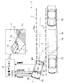
図1は、本発明の実施の各形態で、縦列駐車に対する運転支援の対象となる車両1の外観を示す。車両1が道路2の白線3で区分される走行車線などを走行して走行車線よりも路肩側に後退して駐車しようとする際に、情報ディスプレイ4に縦列駐車支援のための画像情報が表示される。画像情報としては、車両1の進路を予測して算出される進行予測曲線5などが含まれる。進行予測曲線5は、縦列駐車の運転支援を行う電子制御ユニット(以下、「ECU」と略称する)である駐車アシストECU6によって、車両1の操舵を行うステアリング7の操作角であるステアリング角に基づいて算出される。駐車アシストECU6は、変速機のシフトレバー8が、たとえば後退位置に操作され、かつ左右のウインカランプ9L,9Rのうちの左方のウインカランプ9Lが点灯すると、左方への縦列駐車についての支援を開始する。
【0021】
車両1が後退して駐車しようとする際には、車両1の運転者の視覚では車両1の後方は死角となって充分見ることができないので、車両1の車体後部上方にカメラユニット10を装着し、視野10aによって後方の映像を撮像する。カメラユニット10は、たとえばNTSC方式の映像信号を導出し、駐車アシストECU6は、情報ディスプレイ4の表示画面上に、後方映像を進行予測曲線5と重ねて表示する。
【0022】
図2は、図1の車両1が縦列駐車を開始しようとする際の運転支援のための基本的構成を示す。駐車アシストECU6には、カメラユニット10からの映像信号がNTSC方式で入力される。また、ステアリング7のステアリング角は、ステアリング角センサ11によって検知される。ステアリング角センサ11は、ステアリング7の一定角度での角変位毎に、パルス信号を角変位信号として導出する。車両1の変速器を後退用のバックギアの位置に投入するようにシフトレバー8を操作すると、バックランプを点灯させるスイッチ(以下、「SW」と略称する)をONに制御するためのバックランプSW信号12が導出され、駐車アシストECU6に入力される。駐車アシストECU6には、ウインカランプ9L,9Rの点灯信号も入力される。情報ディスプレイ4には、駐車スペース13の映像が表示され、道路2の縁石14なども表示される。駐車スペース13は、たとえば前後の他車両15,16間に設定される。
【0023】
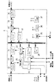
図3は、図1の駐車アシストECU6の概略的な電気的構成を示す。駐車アシストECU6としての全体的な制御は、デジタル信号プロセッサ(以下、「DSP」と略称する)20によって行われる。DSP20は、バス21を介して制御や信号処理を行う。カメラユニット10からはNTSC方式の映像信号が入力され、アンプ+フィルタ回路22で増幅され、映像成分が取出されてアナログデジタル変換(以下、「ADC」と略称する)回路23でアナログ信号からデジタル信号に変換される。デジタル信号に変換された映像成分は、フィールドバッファ回路24に記憶される。アンプ+フィルタ回路22からは、映像信号が同期分離回路25にも入力され、水平同期や垂直同期用の同期成分が分離されて、DSP20に入力される。ステアリング角センサ11からのステアリング角の変位を表す角変位検出信号、およびステアリング7がセンタ位置にあることを示すセンタ位置信号が,バッファ回路26を介してDSP20に入力される。バッファ回路26を介しては、バックランプSW信号およびウインカランプの点灯信号も入力される。DSP20は、バス21を介して接続されるプログラムメモリ27に予め設定されているプログラムに従って動作し、このプログラム動作の際に必要なデータはデータメモリ28から読出したり、データメモリ28に書込んだりすることができる。DSP20は、入力される映像信号に従って、図1の白線3などの認識を行ったり、さらに道路2の縁石の認識を行ったり、他の駐車車両の認識を行ったりすることができる。また認識結果に従って、車両1が目標駐車位置や、車両位置の現在位置から目標駐車位置の移動に必要な理想進行曲線の算出も行うことができる。
【0024】
DSP20は、縦列駐車支援用の画像カメラ20からの映像に重ねるように生成し、SW回路30によって出力が切換え可能なフィールドバッファ回路31,32に記憶する。SW回路30によって選択されるフィールドバッファ回路31,32からの出力は、デジタルアナログ変換(以下、「DAC」と略称する)回路33からフィルタ+アンプ回路34を介して、情報ディスプレイ4に映像出力として与えられる。駐車アシストECU6の全体に対しては、電源35から動作用の電力が供給され、リセット回路36からリセット信号が供給され、CLK+分周回路34から動作タイミングの基本となるクロック信号やその分周信号が供給される。
【0025】
図4は、本発明の実施の一形態として行われる情報ディスプレイ4での画像表示の概要を示す。情報ディスプレイ4上には、カメラユニット10によって撮像される駐車スペース13の映像が表示される。駐車スペース13の前後には、他車両15,16などが存在している。車両1の後端部から駐車スペース13に向けて、現在のステアリング角に基づいて算出される進行予測曲線5が表示される。車両1が駐車スペース13に適切に駐車を行うためには、後退の途中でステアリング7の切り戻しを行わなければならない。駐車アシストECU6は、タイミング判定手段としてステアリング7の切り戻し操作を行うのに適切な位置を進行予測曲線5上で判定し、その位置に斜線のガイドライン40を表示する。ガイドライン40は、ステアリング7の操作で駐車スペース13内の目標駐車位置45に駐車が可能である範囲で、車両1の後退とともに変化した位置に表示される。車両1の運転者は、ガイドライン40が、駐車スペース13の目標となる縁石14などと合致した位置でステアリング7を切り戻せば、駐車を完了させることができる。駐車完了までに、進行予測曲線5が他車両15,16などに接触する恐れが生じるときには、縦列駐車のための後退運転を中止し、車両1を前進させて、可能であれば車両1の姿勢を換えて再度縦列駐車を試みる。
【0026】
図5は、図4の実施形態での制御手順を示す。ステップa1から手順を開始し、ステップa2では所定の縦列駐車アシスト条件が成立しているか否かを判断する。たとえばバックランプSW信号12がONで、ウインカランプ9Lまたはウインカランプ9Rの一方がONであれば縦列駐車アシスト条件は成立していると判断される。なお、ハザードランプとして両方のウィンカランプ9L,9Rを点灯させているときは、通常の縦列駐車方向である左方向に駐車すると判断することもできる。条件成立と判断されるときには、ステップa3で縦列駐車方向を判断する。次にステップa4で、カメラ10が撮像する映像中から目標駐車位置45を検出する。ステップa5では、車両1のステアリング7の操舵角度であるステアリング角を、ステアリング角センサ11からの角変位検出信号に基づいて検出する。ステップa6では、ステアリング角に基づいて進行予測曲線5を算出する。ステップa7では、車両1の現在位置から目標駐車位置45までの移動が、ステアリング操作で可能であるか否かを判断する。可能であると判断されるときには、ステップa8で、ステアリングの切り戻しを行うタイミングを判定する。切り戻しのタイミングが判定されると、進行予測曲線5上で切り戻しを行うタイミングを示すガイドライン40の位置が決定され、画像中に付加される。ステップa10では、ステップa2と同様に、縦列駐車アシスト条件が成立しているか否かを判断する。縦列駐車アシスト条件が成立していれば、ステップa5に戻り、以下同様に駐車アシストを継続する。
【0027】
ステップa7の駐車可能か否かの判断は駐車開始時の車両1の駐車スペース13の位置データを取込み、事前に保持している車両1の並行状態でのガイドライン40のデータとの比較、および車両1の最小回転半径などから判断する。ステップa7で駐車可能でないと判断されるときには、ステップa11で、駐車不可能の案内を、情報ディスプレイ4によって行う。ステップa2またはステップa10で縦列駐車アシスト条件が成立していないと判断されるとき、またはステップa11で駐車不可能案内を行った後は、ステップa12で動作を終了する。
【0028】
図6は、本発明の実施の他の形態での縦列駐車支援の画像を示す。本実施形態で、図4に示す実施形態に対応する部分には同一の参照符を付す。駐車スペース13は、他車両15,16の間に設定され、目標駐車位置45が検出される。現在のステアリング7のステアリング角に基づいて進行予測曲線5が表示され、現在の車両位置から目標駐車位置45までの理想進行曲線46が表示される。車両1の運転者は、進行予測曲線5が理想進行曲線46に沿うようにステアリング7を操作して車両1を後退させることによって、目標駐車位置45への駐車を容易に行うことができる。
【0029】
図7は、図6の実施形態での制御手順を示す。ステップb1からステップb6までの各ステップは、図5のステップa1からステップa6までの各ステップと同等である。ステップb7では、ステップb4で検出した目標駐車位置45に車両1の現在位置から移動するための理想進行曲線46を生成する。理想進行曲線46は、駐車開始時の車両1の現在位置で、駐車スペース13内での目標駐車位置45の位置データを取込み、車両1の最小回転半径や後退速度などに基づいて生成する。ステップb8では、理想進行曲線46の生成が完了しているか否かを判断する。完了していると判断されるときには、ステップb9で、カメラユニット10からの後方映像に、ステップb6で算出した進行予測曲線5と、ステップb7で生成した理想進行曲線46とを重ね合わせて駐車支援の画像を生成して情報ディスプレイ4で表示する。ステップb10では、ステップb2と同様に、縦列駐車アシスト条件が成立しているか否かを判断する。成立していると判断されるときには、ステップb5に戻る。以下ステップb5からステップb10までの各ステップを繰返す。
【0030】
理想進行曲線46に従ってステアリング7の操作を行わなくても、或る程度の範囲までならそのときのステアリング角に応じた理想進行曲線46が表示され、目標駐車位置45に駐車することが可能である。ステップb8で、理想進行曲線46の生成が完了していないと判断されるときには、ステップb11で駐車不可能の案内を行う。ステップb2またはステップb10で縦列駐車アシスト条件が成立していないと判断されるとき、またはステップb11の処理が終了すると、ステップb12で駐車アシスト動作を終了する。
【0031】
以上説明した各実施形態では、カメラユニット10を、縦列駐車のための後方映像の撮像用に使用しているけれども、通常の走行時などで、常時白線3の認識を行い、車線逸脱などをモニタリングする車線逸脱モニタ用としても兼用することができる。縦列駐車の支援用の後方監視用カメラと車線逸脱モニタ用カメラとをカメラユニット10で兼用することによって、車載カメラの搭載数を削減することができ、コストダウンを図ることができる。
【0032】
【発明の効果】
以上のように本発明によれば、車両が後退して縦列駐車を行う際に、車両の後方映像にステアリング角とバックランプおよびウインカランプの点灯信号とに基づく進行予測曲線が重ねて表示され、さらに目標駐車位置までの理想進行曲線が付加されるので、車両の運転者は案内情報に従ってステアリング操作を行い、縦列駐車を容易に行うことができる。
また、縦列駐車の支援を開始する操作として、単に運転操作に必要な操作を行えば自動的に支援が開始されるので、縦列駐車時のスイッチ操作の繁雑さをなくすことができる。
また、縦列駐車を行う方向が車両の左方であるか右方であるかを、ハザードランプ及び/またはウインカランプの点灯状態の組合わせに従って判断するので、自動的に適切な方向での縦列駐車の支援を行うことができる。
【0033】
また本発明によれば、ステアリングの切り戻しを行う位置が、進行予測曲線に線で示されるガイドラインから分かるので、ガイドラインと目標との関係に基づいてステアリング操作を行い、容易に縦列駐車を行うことができる。
【0036】
また本発明によれば、カメラの映像は、車線逸脱監視用にも用いられるので、駐車支援と車線逸脱監視とに別々にカメラを搭載する必要はなく、カメラを共用化してコストの低減を図ることができる。
【0037】
また本発明によれば、縦列駐車の可否を前もって判断し、縦列駐車が可能でないと判断されるときには、車両の姿勢を換えたり、他の駐車スペースを探すようにすることができる。
また本発明によれば、車両が後退して縦列駐車を行う際に、車両の後方映像にステアリング角とバックランプおよびウインカランプの点灯信号とに基づく進行予測曲線が重ねて表示され、さらに目標駐車位置までの理想進行曲線が付加されるので、車両の運転者は案内情報に従ってステアリング操作を行い、縦列駐車を容易に行うことができる。
【図面の簡単な説明】
【図1】本発明の実施の各形態で縦列駐車アシストを行う基本的な構成を示すブロック図である。
【図2】図1の構成で縦列駐車を行う状態を示す簡略化した平面図である。
【図3】図1の駐車アシストECU6の電気的構成を示すブロック図である。
【図4】本発明の実施の第1形態としての縦列駐車支援用の画像を示す図である。
【図5】図4の実施形態の制御手順を示すフローチャートである。
【図6】本発明の実施の他の形態での縦列駐車支援の画像を示す図である。
【図7】図6の実施形態での制御手順を示すフローチャートである。
【符号の説明】
1 車両
2 道路
3 白線
4 情報ディスプレイ
5 進行予測曲線
6 駐車アシストECU
7 ステアリング
8 シフトレバー
9L,9R ウインカランプ
10 カメラユニット
10a 視野
11 ステアリング角センサ
12 バックランプSW信号
13 駐車スペース
15,16 他車両
20 DSP
27 プログラムメモリ
28 データメモリ
40 ガイドライン
45 目標駐車位置
46 理想進行曲線[0001]
BACKGROUND OF THE INVENTION
The present invention relates to a parking support device for a vehicle that supports driving operation for a driver when the vehicle is parked, and more particularly to a parking support device for a vehicle that supports driving operation when the vehicle moves backward and performs parallel parking.
[0002]
[Prior art]
Traditionally, vehicle parking, particularly parallel parking, has been one of the most technically difficult for a normal driver to drive a vehicle. In parallel parking, the vehicle must be moved back into a narrow parking space and the steering operation must be switched back. Moreover, since the vehicle is parked in reverse, the driving operation must be performed in a state where the surrounding area of the parking space is a blind spot from the driver and sufficient information cannot be obtained.
[0003]
Prior art for assisting the driver when performing parallel parking is disclosed in, for example, Japanese Patent Laid-Open No. 7-44799. In this prior art, the parking space is measured once passing through the side of the place where the parallel parking is performed, and the steering operation amount and the information on the measured parking space and the information on the vehicle are measured. The driver is guided to obtain the accelerator operation time or the brake operation time.
[0004]
[Problems to be solved by the invention]
In the prior art of Japanese Patent Laid-Open No. 7-44799, the measurement of the parking space is described in detail, but the driving operation necessary for parking is only described instructing the driver. It is unclear what kind of instruction is given.
[0005]
An object of the present invention is to provide a vehicle parking assistance device capable of assisting a driving operation in an easy-to-understand manner for a vehicle driver when performing parallel parking.
[0006]
[Means for Solving the Problems]
The present invention relates to a vehicle parking assistance device that supports driving operation of parallel parking for a vehicle driver with guidance based on image information.
A camera that captures the rear image of the vehicle;
A steering angle sensor for detecting the steering angle of the vehicle;
A processor to which lighting signals of a vehicle back lamp and a blinker lamp are input;
A course prediction means for predicting the direction of parallel parking and the course of the vehicle based on the steering angle detected by the steering angle sensor and the lighting signals of the back lamp and the blinker lamp, and calculating a progress prediction curve;
A progress curve calculating means for detecting a target parking position based on an image captured by the camera and calculating an ideal progress curve from the current position of the vehicle to the target parking position;
Generating a composite image of a video captured by the camera, a progress prediction curve predicted by the course prediction means, and an ideal progress curve from the current position of the vehicle to the target parking position calculated by the progress curve calculation means Parking assistance means,
The vehicle parking assistance device further comprises display means for displaying the composite image generated by the parking assistance means.
[0007]
According to the present invention, the rear image of the vehicle is captured by the camera, and the steering angle of the vehicle is detected by the steering angle sensor. The course prediction means predicts the course of the vehicle based on the steering angle detected by the steering angle sensor and the lighting signals of the back lamp and the blinker lamp, and calculates a progress prediction curve. The progress curve calculation means detects the target parking position based on the video imaged by the camera, and calculates an ideal progress curve from the current position of the vehicle to the target parking position. The parking assist means generates a composite image of the image captured by the camera, the progress prediction curve predicted by the course prediction means, and the ideal progress curve from the current position of the vehicle to the target parking position calculated by the progress curve calculation means. Generate. Along with the rear image of the vehicle, a progress prediction curve corresponding to the steering angle and the lighting signal of the back lamp and the blinker lamp is displayed, and an ideal progress curve from the current position to the target parking position is displayed as guidance information for the steering operation. Therefore, the driver of the vehicle can easily perform the driving operation for parallel parking if he / she operates the steering so that the progress prediction curve follows the ideal progress curve while looking at the display means.
In addition, parallel parking support is provided on the condition that the vehicle is in reverse and the back lamp and the unloading lamp are lit, so there is no need for a switch operation to start parallel parking support, and parallel parking is performed outside the vehicle. If the operation of turning on the back lamp and the blinker lamp is performed as a cue to start the operation, it is possible to automatically support the parallel parking, and the complexity of the switch operation can be eliminated.
If one of the blinker lamps is lit, the illuminated blinker lamp side can be assisted to add parallel parking guidance information, thereby eliminating complicated switch operations.
[0008]
In the present invention, the parking support means may add a guideline as a line to the position on the progress prediction curve where the steering should be switched back as the steering operation guidance information.
[0009]
According to the present invention, as guide information of the steering operation, since the addition of guidelines position on progression prediction curve should be performed back steering cut as a line, at the point where guidelines consistent with curbs which is a target of the parking space Turn the steering wheel back to complete parking. As a result, the driver can easily perform parallel parking, and can prevent contact with a vehicle parked adjacently.
[0016]
The present invention further includes lane monitoring means for recognizing a lane boundary by monitoring a lane boundary from the video from the camera.
[0017]
According to the present invention, the camera for monitoring the rear is used to recognize the boundary of the lane and to monitor whether the vehicle departs from the lane. Therefore, the rear monitoring camera for parking assistance and the lane departure monitoring camera are used. The cost can be reduced as compared with the case where the camera is mounted separately.
[0018]
In the present invention, the parking assist means can move the vehicle backward and move to a target parking position detected by the progress curve calculating means within a steerable steering angle range, and the lane monitoring means. It is determined whether or not to depart from the lane monitored by the vehicle, and parking assistance is performed based on the determination result.
[0019]
According to the present invention, it is determined whether or not the vehicle can move backward and move to the target parking position within the operable steering angle range and does not deviate from the lane recognized by the lane monitoring means. Since parking assistance is performed, it is possible to easily perform parallel parking by retracting the vehicle without departing from the lane.
In addition, the present invention provides a vehicle parking support apparatus that supports driving operation of parallel parking for a driver of a vehicle by guidance based on image information.
A course prediction means for predicting a direction of parallel parking and a course of the vehicle based on a steering angle of the vehicle and a lighting signal of a back lamp and a blinker lamp of the vehicle, and calculating a progress prediction curve;
A progress curve calculating means for detecting a target parking position based on a rear image of the vehicle imaged by the camera and calculating an ideal progress curve from the current position of the vehicle to the target parking position;
A composite image of a rear image captured by the camera, a progress prediction curve predicted by the course prediction means, and an ideal progress curve from the current position of the vehicle to the target parking position calculated by the progress curve calculation means. Parking assist means to generate,
The vehicle parking assistance device further comprises display means for displaying the composite image generated by the parking assistance means.
According to the present invention, the course prediction means predicts the direction of parallel parking and the course of the vehicle based on the steering angle of the vehicle and the lighting signals of the back lamp and the blinker lamp of the vehicle, and calculates a progress prediction curve. To do. The progress curve calculation means detects the target parking position based on the rear image captured by the camera, and calculates an ideal progress curve from the current position of the vehicle to the target parking position. The parking support means is a composite image of the rear image captured by the camera, the progress prediction curve predicted by the course prediction means, and the ideal progress curve from the current position of the vehicle to the target parking position calculated by the progress curve calculation means. Is generated. Along with the rear image of the vehicle, a progress prediction curve corresponding to the steering angle and lighting signals of the back lamp and the blinker lamp is displayed, and an ideal progress curve from the current position to the target parking position is displayed as guidance information for steering operation. Therefore, the driver of the vehicle can easily perform the driving operation for parallel parking if he / she operates the steering so that the progress prediction curve follows the ideal progress curve while looking at the display means.
[0020]
DETAILED DESCRIPTION OF THE INVENTION
FIG. 1 shows the appearance of a
[0021]
When the
[0022]
FIG. 2 shows a basic configuration for driving support when the
[0023]
FIG. 3 shows a schematic electrical configuration of the parking assist
[0024]
The
[0025]
FIG. 4 shows an outline of image display on the
[0026]
FIG. 5 shows a control procedure in the embodiment of FIG. The procedure starts from step a1, and in step a2, it is determined whether or not a predetermined parallel parking assist condition is satisfied. For example, if the back
[0027]
In step a7, whether or not parking is possible is determined by taking the position data of the
[0028]
FIG. 6 shows an image of parallel parking assistance in another embodiment of the present invention. In this embodiment, the same reference numerals are given to portions corresponding to the embodiment shown in FIG. The
[0029]
FIG. 7 shows a control procedure in the embodiment of FIG. Each step from step b1 to step b6 is equivalent to each step from step a1 to step a6 in FIG. In step b7, an
[0030]
Even if the
[0031]
In each of the embodiments described above, the
[0032]
【The invention's effect】
As described above, according to the present invention, when the vehicle moves backward and performs parallel parking, the progress prediction curve based on the steering angle and the lighting signal of the back lamp and the blinker lamp is displayed superimposed on the rear image of the vehicle, Furthermore, since an ideal travel curve to the target parking position is added, the driver of the vehicle can easily perform parallel parking by performing a steering operation according to the guidance information.
In addition, as an operation for starting support for parallel parking, simply performing an operation required for driving operation automatically starts support, so that the complexity of switch operation during parallel parking can be eliminated.
In addition, it determines whether the direction of parallel parking is the left side or the right side of the vehicle according to the combination of the lighting state of the hazard lamp and / or the blinker lamp, so the parallel parking in the appropriate direction automatically. Can be supported.
[0033]
Further, according to the present invention, the position at which the steering is switched back can be found from the guideline indicated by a line in the progress prediction curve, so that the steering operation is performed based on the relationship between the guideline and the target, and the parallel parking is easily performed. Can do.
[0036]
Further, according to the present invention, since the video of the camera is also used for lane departure monitoring, it is not necessary to mount separate cameras for parking assistance and lane departure monitoring, and the cost is reduced by sharing the camera. be able to.
[0037]
Further, according to the present invention, whether or not parallel parking is possible is determined in advance, and when it is determined that parallel parking is not possible, the posture of the vehicle can be changed or another parking space can be searched.
Further, according to the present invention, when the vehicle moves backward and performs parallel parking, a progress prediction curve based on the steering angle and the lighting signals of the back lamp and the blinker lamp is displayed superimposed on the rear image of the vehicle, and the target parking is further performed. Since the ideal travel curve to the position is added, the vehicle driver can perform the steering operation according to the guidance information, and can easily perform parallel parking.
[Brief description of the drawings]
FIG. 1 is a block diagram showing a basic configuration for performing parallel parking assistance in each embodiment of the present invention.
FIG. 2 is a simplified plan view showing a state where parallel parking is performed with the configuration of FIG. 1;
FIG. 3 is a block diagram showing an electrical configuration of the parking assist
FIG. 4 is a diagram showing an image for supporting parallel parking as the first embodiment of the present invention.
FIG. 5 is a flowchart showing a control procedure of the embodiment of FIG. 4;
FIG. 6 is a diagram showing an image of parallel parking support in another embodiment of the present invention.
7 is a flowchart showing a control procedure in the embodiment of FIG.
[Explanation of symbols]
1
7 Steering 8
27
Claims (5)
車両の後方映像を撮像するカメラと、
車両のステアリング角を検出するステアリング角センサと、
車両のバックランプおよびウインカランプの点灯信号が入力されるプロセッサと、
前記ステアリング角センサによって検出されるステアリング角と前記バックランプおよびウインカランプの点灯信号とに基づいて、縦列駐車の方向および車両の進路を予測して進行予測曲線を算出する進路予測手段と、
前記カメラによって撮像された映像に基づいて、目標駐車位置を検出し、車両の現在位置から前記目標駐車位置までの理想進行曲線を算出する進行曲線算出手段と、
前記カメラによって撮像された映像と前記進路予測手段によって予測される進行予測曲線と、前記進行曲線算出手段によって算出される車両の現在位置から前記目標駐車位置までの理想進行曲線との合成画像を生成する駐車支援手段と、
前記駐車支援手段によって生成された合成画像を表示する表示手段とを備えることを特徴とする車両の駐車支援装置。In the vehicle parking assistance device that supports the driving operation of the parallel parking for the driver of the vehicle by the guidance by the image information,
A camera that captures the rear image of the vehicle;
A steering angle sensor for detecting the steering angle of the vehicle;
A processor to which lighting signals of a vehicle back lamp and a blinker lamp are input;
A course prediction means for predicting the direction of parallel parking and the course of the vehicle based on the steering angle detected by the steering angle sensor and the lighting signals of the back lamp and the blinker lamp, and calculating a progress prediction curve;
A progress curve calculating means for detecting a target parking position based on an image captured by the camera and calculating an ideal progress curve from the current position of the vehicle to the target parking position;
Generating a composite image of a video captured by the camera, a progress prediction curve predicted by the course prediction means, and an ideal progress curve from the current position of the vehicle to the target parking position calculated by the progress curve calculation means Parking assistance means,
A vehicle parking assistance apparatus comprising: display means for displaying a composite image generated by the parking assistance means.
車両のステアリング角と、車両のバックランプおよびウインカランプの点灯信号とに基づいて、縦列駐車の方向および車両の進路を予測して進行予測曲線を算出する進路予測手段と、
カメラによって撮像された車両の後方映像に基づいて、目標駐車位置を検出し、車両の現在位置から前記目標駐車位置までの理想進行曲線を算出する進行曲線算出手段と、
前記カメラによって撮像された後方映像と前記進路予測手段によって予測される進行予測曲線と、前記進行曲線算出手段によって算出される車両の現在位置から前記目標駐車位置までの理想進行曲線との合成画像を生成する駐車支援手段と、
前記駐車支援手段によって生成された合成画像を表示する表示手段とを備えることを特徴とする車両の駐車支援装置。In the vehicle parking assistance device that supports the driving operation of the parallel parking for the driver of the vehicle by the guidance by the image information,
A course prediction means for predicting a direction of parallel parking and a course of the vehicle based on a steering angle of the vehicle and a lighting signal of a back lamp and a blinker lamp of the vehicle, and calculating a progress prediction curve;
A progress curve calculating means for detecting a target parking position based on a rear image of the vehicle imaged by the camera and calculating an ideal progress curve from the current position of the vehicle to the target parking position;
A composite image of a rear image captured by the camera, a progress prediction curve predicted by the course prediction means, and an ideal progress curve from the current position of the vehicle to the target parking position calculated by the progress curve calculation means. Parking assist means to generate,
A vehicle parking assistance apparatus comprising: display means for displaying a composite image generated by the parking assistance means.
Priority Applications (10)
| Application Number | Priority Date | Filing Date | Title |
|---|---|---|---|
| JP18344999A JP4426014B2 (en) | 1999-06-29 | 1999-06-29 | Vehicle parking assist device |
| US09/598,270 US7366595B1 (en) | 1999-06-25 | 2000-06-21 | Vehicle drive assist system |
| EP03028607A EP1400410B1 (en) | 1999-06-25 | 2000-06-22 | Vehicle drive assist system |
| DE60031011T DE60031011T2 (en) | 1999-06-25 | 2000-06-22 | Driver assistance system for vehicles |
| EP07116713A EP1870870B1 (en) | 1999-06-25 | 2000-06-22 | Vehicle drive assist system |
| DE60037222T DE60037222T2 (en) | 1999-06-25 | 2000-06-22 | Driver assistance system for vehicles |
| DE60044625T DE60044625D1 (en) | 1999-06-25 | 2000-06-22 | Système d'assistance de conduire pour vehicules |
| EP00305278A EP1065642B1 (en) | 1999-06-25 | 2000-06-22 | Vehicle drive assist system |
| US11/503,899 US7640107B2 (en) | 1999-06-25 | 2006-08-15 | Vehicle drive assist system |
| US11/504,013 US7640108B2 (en) | 1999-06-25 | 2006-08-15 | Vehicle drive assist system |
Applications Claiming Priority (1)
| Application Number | Priority Date | Filing Date | Title |
|---|---|---|---|
| JP18344999A JP4426014B2 (en) | 1999-06-29 | 1999-06-29 | Vehicle parking assist device |
Publications (3)
| Publication Number | Publication Date |
|---|---|
| JP2001010431A JP2001010431A (en) | 2001-01-16 |
| JP2001010431A5 JP2001010431A5 (en) | 2006-08-10 |
| JP4426014B2 true JP4426014B2 (en) | 2010-03-03 |
Family
ID=16135982
Family Applications (1)
| Application Number | Title | Priority Date | Filing Date |
|---|---|---|---|
| JP18344999A Expired - Lifetime JP4426014B2 (en) | 1999-06-25 | 1999-06-29 | Vehicle parking assist device |
Country Status (1)
| Country | Link |
|---|---|
| JP (1) | JP4426014B2 (en) |
Cited By (2)
| Publication number | Priority date | Publication date | Assignee | Title |
|---|---|---|---|---|
| CN108128245A (en) * | 2016-12-01 | 2018-06-08 | 通用汽车环球科技运作有限责任公司 | Vehicle environmental imaging system and method |
| CN110435644A (en) * | 2019-08-16 | 2019-11-12 | 广州小鹏汽车科技有限公司 | It parks control method, device, storage medium and controlling terminal |
Families Citing this family (18)
| Publication number | Priority date | Publication date | Assignee | Title |
|---|---|---|---|---|
| JP3427823B2 (en) * | 2000-02-29 | 2003-07-22 | 株式会社豊田自動織機 | Backing support device for parallel parking |
| JP4491978B2 (en) * | 2000-02-29 | 2010-06-30 | アイシン精機株式会社 | Vehicle reverse assist device and reverse assist method |
| JP4583553B2 (en) * | 2000-05-31 | 2010-11-17 | アイシン精機株式会社 | Parking assistance device |
| JP2002240661A (en) * | 2001-02-19 | 2002-08-28 | Nissan Motor Co Ltd | Parking support device |
| JP4918200B2 (en) * | 2001-04-24 | 2012-04-18 | パナソニック株式会社 | Parking driving support device |
| JP4765213B2 (en) * | 2001-07-19 | 2011-09-07 | 日産自動車株式会社 | Parking assistance device for vehicles |
| JP4576772B2 (en) * | 2001-08-24 | 2010-11-10 | 日産自動車株式会社 | Parking assistance device |
| JP4342146B2 (en) * | 2002-04-08 | 2009-10-14 | アイシン精機株式会社 | Parking assistance device |
| SE525848C2 (en) | 2002-12-17 | 2005-05-10 | Volvo Lastvagnar Ab | Ranking device for a vehicle as well as a method for facilitating vehicle ranking |
| DE10332961A1 (en) * | 2003-07-21 | 2005-02-17 | Robert Bosch Gmbh | Method and device for determining the position and / or the expected position of a vehicle during a parking operation in relation to the opposite lane of a multi-lane road |
| JP4481042B2 (en) * | 2004-03-10 | 2010-06-16 | クラリオン株式会社 | Parking assistance system |
| DE102004027640A1 (en) * | 2004-06-05 | 2006-06-08 | Robert Bosch Gmbh | Method and device for assisted parking of a motor vehicle |
| JP4437071B2 (en) * | 2004-12-24 | 2010-03-24 | パナソニック株式会社 | Driving assistance device |
| JP4148229B2 (en) * | 2005-02-14 | 2008-09-10 | 株式会社デンソー | Vehicle display device |
| EP2246231B1 (en) * | 2009-04-30 | 2011-10-26 | Magneti Marelli S.p.A. | Parking assistant system |
| KR101795151B1 (en) | 2015-10-05 | 2017-12-01 | 현대자동차주식회사 | Parking guidance apparatus and method for vehicle |
| JP6387369B2 (en) | 2016-05-23 | 2018-09-05 | 本田技研工業株式会社 | Travel control device |
| JP7008235B2 (en) * | 2017-10-26 | 2022-01-25 | パナソニックIpマネジメント株式会社 | Parking support device |
-
1999
- 1999-06-29 JP JP18344999A patent/JP4426014B2/en not_active Expired - Lifetime
Cited By (4)
| Publication number | Priority date | Publication date | Assignee | Title |
|---|---|---|---|---|
| CN108128245A (en) * | 2016-12-01 | 2018-06-08 | 通用汽车环球科技运作有限责任公司 | Vehicle environmental imaging system and method |
| CN108128245B (en) * | 2016-12-01 | 2021-05-07 | 通用汽车环球科技运作有限责任公司 | Vehicle environment imaging system and method |
| CN110435644A (en) * | 2019-08-16 | 2019-11-12 | 广州小鹏汽车科技有限公司 | It parks control method, device, storage medium and controlling terminal |
| CN110435644B (en) * | 2019-08-16 | 2023-10-31 | 广州小鹏汽车科技有限公司 | Parking control method and device, storage medium and control terminal |
Also Published As
| Publication number | Publication date |
|---|---|
| JP2001010431A (en) | 2001-01-16 |
Similar Documents
| Publication | Publication Date | Title |
|---|---|---|
| JP4426014B2 (en) | Vehicle parking assist device | |
| JP4536889B2 (en) | Vehicle driving support device | |
| US6411867B1 (en) | Vehicle driving support system, and steering angle detection device | |
| JP4622806B2 (en) | Parking support method and parking support device | |
| KR100788027B1 (en) | Parking assist apparatus for vehicle | |
| JP4900232B2 (en) | Vehicle parking assist device and video display method | |
| JP2001010427A (en) | Vehicle parking assist device | |
| JP4696691B2 (en) | Parking support method and parking support device | |
| JP2003054340A (en) | Support device for parking | |
| JP3917008B2 (en) | Automatic steering control device | |
| JP2009083680A (en) | Parking assistance device and parking assistance method | |
| CN112298038A (en) | Periphery monitoring device | |
| JP4350838B2 (en) | Vehicle driving support device | |
| JP2019051822A (en) | Parking support device | |
| JP2007118922A (en) | Vehicular reverse operation assisting device | |
| JP4479183B2 (en) | Video presentation device | |
| JP3739269B2 (en) | Vehicle driving support device | |
| JP2001010429A (en) | Vehicle operation assist device | |
| JP2004051063A (en) | Device for visual recognition around vehicle | |
| JP2012166689A (en) | Driving assistance apparatus | |
| JP2010076765A (en) | Travel recorder | |
| JP3541792B2 (en) | Backing support device for parallel parking | |
| JP2003212072A (en) | Driving support device | |
| JP2017188761A (en) | Vehicle periphery display device and vehicle periphery display method | |
| JP2010067095A (en) | Drive assist device |
Legal Events
| Date | Code | Title | Description |
|---|---|---|---|
| A521 | Request for written amendment filed |
Free format text: JAPANESE INTERMEDIATE CODE: A523 Effective date: 20060626 |
|
| A621 | Written request for application examination |
Free format text: JAPANESE INTERMEDIATE CODE: A621 Effective date: 20060626 |
|
| A977 | Report on retrieval |
Free format text: JAPANESE INTERMEDIATE CODE: A971007 Effective date: 20081127 |
|
| A131 | Notification of reasons for refusal |
Free format text: JAPANESE INTERMEDIATE CODE: A131 Effective date: 20081202 |
|
| A521 | Request for written amendment filed |
Free format text: JAPANESE INTERMEDIATE CODE: A523 Effective date: 20090202 |
|
| A131 | Notification of reasons for refusal |
Free format text: JAPANESE INTERMEDIATE CODE: A131 Effective date: 20090707 |
|
| A521 | Request for written amendment filed |
Free format text: JAPANESE INTERMEDIATE CODE: A523 Effective date: 20090907 |
|
| TRDD | Decision of grant or rejection written | ||
| A01 | Written decision to grant a patent or to grant a registration (utility model) |
Free format text: JAPANESE INTERMEDIATE CODE: A01 Effective date: 20091208 |
|
| A01 | Written decision to grant a patent or to grant a registration (utility model) |
Free format text: JAPANESE INTERMEDIATE CODE: A01 |
|
| A61 | First payment of annual fees (during grant procedure) |
Free format text: JAPANESE INTERMEDIATE CODE: A61 Effective date: 20091210 |
|
| R150 | Certificate of patent or registration of utility model |
Ref document number: 4426014 Country of ref document: JP Free format text: JAPANESE INTERMEDIATE CODE: R150 Free format text: JAPANESE INTERMEDIATE CODE: R150 |
|
| FPAY | Renewal fee payment (event date is renewal date of database) |
Free format text: PAYMENT UNTIL: 20121218 Year of fee payment: 3 |
|
| FPAY | Renewal fee payment (event date is renewal date of database) |
Free format text: PAYMENT UNTIL: 20131218 Year of fee payment: 4 |
|
| FPAY | Renewal fee payment (event date is renewal date of database) |
Free format text: PAYMENT UNTIL: 20131218 Year of fee payment: 4 |
|
| EXPY | Cancellation because of completion of term |