JP4425785B2 - Image forming method and product providing a durable assembly - Google Patents
Image forming method and product providing a durable assembly Download PDFInfo
- Publication number
- JP4425785B2 JP4425785B2 JP2004505805A JP2004505805A JP4425785B2 JP 4425785 B2 JP4425785 B2 JP 4425785B2 JP 2004505805 A JP2004505805 A JP 2004505805A JP 2004505805 A JP2004505805 A JP 2004505805A JP 4425785 B2 JP4425785 B2 JP 4425785B2
- Authority
- JP
- Japan
- Prior art keywords
- layer
- donor
- image
- weight
- group
- Prior art date
- Legal status (The legal status is an assumption and is not a legal conclusion. Google has not performed a legal analysis and makes no representation as to the accuracy of the status listed.)
- Expired - Fee Related
Links
Images


Classifications
-
- G—PHYSICS
- G03—PHOTOGRAPHY; CINEMATOGRAPHY; ANALOGOUS TECHNIQUES USING WAVES OTHER THAN OPTICAL WAVES; ELECTROGRAPHY; HOLOGRAPHY
- G03G—ELECTROGRAPHY; ELECTROPHOTOGRAPHY; MAGNETOGRAPHY
- G03G5/00—Recording members for original recording by exposure, e.g. to light, to heat, to electrons; Manufacture thereof; Selection of materials therefor
- G03G5/02—Charge-receiving layers
- G03G5/04—Photoconductive layers; Charge-generation layers or charge-transporting layers; Additives therefor; Binders therefor
-
- C—CHEMISTRY; METALLURGY
- C08—ORGANIC MACROMOLECULAR COMPOUNDS; THEIR PREPARATION OR CHEMICAL WORKING-UP; COMPOSITIONS BASED THEREON
- C08L—COMPOSITIONS OF MACROMOLECULAR COMPOUNDS
- C08L67/00—Compositions of polyesters obtained by reactions forming a carboxylic ester link in the main chain; Compositions of derivatives of such polymers
- C08L67/04—Polyesters derived from hydroxycarboxylic acids, e.g. lactones
-
- B—PERFORMING OPERATIONS; TRANSPORTING
- B41—PRINTING; LINING MACHINES; TYPEWRITERS; STAMPS
- B41M—PRINTING, DUPLICATING, MARKING, OR COPYING PROCESSES; COLOUR PRINTING
- B41M5/00—Duplicating or marking methods; Sheet materials for use therein
- B41M5/50—Recording sheets characterised by the coating used to improve ink, dye or pigment receptivity, e.g. for ink-jet or thermal dye transfer recording
- B41M5/52—Macromolecular coatings
-
- B—PERFORMING OPERATIONS; TRANSPORTING
- B41—PRINTING; LINING MACHINES; TYPEWRITERS; STAMPS
- B41M—PRINTING, DUPLICATING, MARKING, OR COPYING PROCESSES; COLOUR PRINTING
- B41M2205/00—Printing methods or features related to printing methods; Location or type of the layers
- B41M2205/02—Dye diffusion thermal transfer printing (D2T2)
-
- B—PERFORMING OPERATIONS; TRANSPORTING
- B41—PRINTING; LINING MACHINES; TYPEWRITERS; STAMPS
- B41M—PRINTING, DUPLICATING, MARKING, OR COPYING PROCESSES; COLOUR PRINTING
- B41M2205/00—Printing methods or features related to printing methods; Location or type of the layers
- B41M2205/38—Intermediate layers; Layers between substrate and imaging layer
-
- B—PERFORMING OPERATIONS; TRANSPORTING
- B41—PRINTING; LINING MACHINES; TYPEWRITERS; STAMPS
- B41M—PRINTING, DUPLICATING, MARKING, OR COPYING PROCESSES; COLOUR PRINTING
- B41M5/00—Duplicating or marking methods; Sheet materials for use therein
- B41M5/50—Recording sheets characterised by the coating used to improve ink, dye or pigment receptivity, e.g. for ink-jet or thermal dye transfer recording
- B41M5/52—Macromolecular coatings
- B41M5/5236—Macromolecular coatings characterised by the use of natural gums, of proteins, e.g. gelatins, or of macromolecular carbohydrates, e.g. cellulose
-
- C—CHEMISTRY; METALLURGY
- C08—ORGANIC MACROMOLECULAR COMPOUNDS; THEIR PREPARATION OR CHEMICAL WORKING-UP; COMPOSITIONS BASED THEREON
- C08L—COMPOSITIONS OF MACROMOLECULAR COMPOUNDS
- C08L1/00—Compositions of cellulose, modified cellulose or cellulose derivatives
- C08L1/08—Cellulose derivatives
- C08L1/10—Esters of organic acids, i.e. acylates
- C08L1/14—Mixed esters, e.g. cellulose acetate-butyrate
Description
本発明は、レーザー誘起熱転写方法に供される受容体要素の画像受容層に関する。 The present invention relates to an image receiving layer of a receiver element that is subjected to a laser induced thermal transfer method.
(関連出願の相互参照)
本願は、2002年5月13日出願の米国仮出願第60/380,340号による利益を請求する。該仮出願は、その全体が参照により本明細書に援用されるものとする。
(Cross-reference of related applications)
This application claims the benefit of US Provisional Application No. 60 / 380,340, filed May 13, 2002. The provisional application is hereby incorporated by reference in its entirety.
レーザー誘起熱転写方法は、カラープルーフィング、電子回路製造、カラーフィルター、リソグラフィー、および他の領域のような用途で使用される周知の画像形成方法である。そのようなレーザー誘起方法としては、たとえば、染料昇華、染料転写、溶融転写、および融除物質転写が挙げられる。これらの方法については、たとえば、バルドック(Baldock)の英国特許公報(特許文献1)、ドブール(DeBoer)の米国特許公報(特許文献2)、ケロッグ(Kellogg)の米国特許公報(特許文献3)、エバンス(Evans)の米国特許公報(特許文献4)、フォーレイ(Foley)らの米国特許公報(特許文献5)、エリス(Ellis)らの米国特許公報(特許文献6)、および腰塚らの米国特許公報(特許文献7)に記載されている。 Laser induced thermal transfer methods are well known imaging methods used in applications such as color proofing, electronic circuit manufacturing, color filters, lithography, and other areas. Such laser induced methods include, for example, dye sublimation, dye transfer, melt transfer, and ablation material transfer. These methods include, for example, Baldock's UK Patent Publication (Patent Document 1), DeBoer's US Patent Publication (Patent Document 2), Kellogg's US Patent Publication (Patent Document 3), Evans US Patent Publication (Patent Document 4), Foley et al. US Patent Publication (Patent Document 5), Ellis et al. US Patent Publication (Patent Document 6), and Koshizuka et al. US Patent It is described in the gazette (patent document 7).
レーザー誘起方法では、(a)転写させる物質(たとえば、染料、顔料、または顔料着色層のような着色材)を含む供与体層を含有する供与体要素と、(b)受容表面を有する接触状態にある受容体要素とを備えるレーザー適性集成体が使用される。レーザー適性集成体がレーザー(通常、赤外線レーザー)により画像様に露光されると、供与体要素の供与体層から受容体要素の受容表面上または受容表面下まで物質が転写される。各画像様露光は1回につきレーザー適性集成体の小選択領域にのみ行われ、その結果として、画像形成性要素から受容体要素への転写物を、1回につき1ピクセルまたは1領域で堆積させることができる。コンピューター制御により、高解像度かつ高速度で転写が達成される。先に記載したようにレーザーによる画像様露光が行われた後のレーザー適性集成体を、これ以降では、画像化レーザー適性集成体と呼ぶ。 In a laser-induced method, (a) a donor element containing a donor layer containing a material to be transferred (eg, a dye, pigment, or colorant such as a pigmented layer) and (b) a contact state having a receiving surface A laser-compatible assembly with a receiver element in the middle is used. When the laser-compatible assembly is imagewise exposed by a laser (usually an infrared laser), the material is transferred from the donor layer of the donor element to the receiving surface of the receiving element or below the receiving surface. Each imagewise exposure is only performed on a small selection area of the laser-compatible assembly at one time, resulting in a transfer of imageable element to receiver element transfer at one pixel or area at a time. be able to. By computer control, transfer is achieved at high resolution and high speed. A laser-suitable assembly after imagewise exposure with a laser as described above is referred to hereinafter as an imaging laser suitability assembly.
画像化レーザー適性集成体は、2つの要素、すなわち、(c)非露光領域の物質を含有する熱画像形成性要素と、(d)露光領域から転写された物質を含有する画像化受容体要素と、に分離可能である。後続の(多くの場合、異なる)画像様露光で他の物質を画像様に転写するために、画像化受容体要素を新しいレーザー適性集成体に上述したごとく組み入れることができる。そのような反復方法によれば、異なる集成体を用いて画像様に転写された多くの異なる物質を組み入れてなる画像化受容体要素を作製することができる。たとえば、マルチカラープルーフまたはカラーフィルターを作製するために、異なる物質は、それぞれ、着色材を含みうる。画像化受容体要素は、それ自体、受容層と転写物質とを含む多要素集成体と見なすことができ、カラープルーフ、カラーフィルター、または印刷プレートとして有用でありうる。しかしながら、多くの場合、最終集成体(たとえば、カラープルーフ、カラーフィルター、または印刷要素)を作製するために、画像化受容体要素は、周知の技術により、他の要素または材料と併用される。 The imaging laser suitability assembly comprises two elements: (c) a thermal imageable element containing material in an unexposed area, and (d) an imaged receiver element containing substance transferred from the exposed area. And can be separated. The imaged receiver element can be incorporated into a new laser-compatible assembly as described above for imagewise transfer of other materials in subsequent (often different) imagewise exposures. Such iterative methods can produce imaging receptor elements that incorporate many different materials that are imagewise transferred using different assemblies. For example, to make a multicolor proof or color filter, the different materials can each contain a colorant. The imaging receiver element can itself be viewed as a multi-element assembly comprising a receiving layer and a transfer material, and can be useful as a color proof, color filter, or printing plate. However, in many cases, the imaging receiver element is used in combination with other elements or materials by well-known techniques to make the final assembly (eg, color proof, color filter, or printing element).
受容体要素を利用するレーザー誘起熱画像形成方法および製品は、カスパー(Caspar)らの米国特許公報(特許文献8)、山崎らの米国特許公報(特許文献9)、および臼杵らの米国特許公報(特許文献10)に記載されている。米国特許公報(特許文献8)では、カプロラクトンポリマーが受容体要素中で使用されている。 Laser-induced thermal imaging methods and products that utilize receptor elements are disclosed in Caspar et al., US Pat. No. 5,099,096, Yamazaki et al., US Pat. (Patent Document 10). In US Patent Publication (Patent Document 8), a caprolactone polymer is used in the receptor element.
米国特許公報(特許文献9)は、基材シートと、基材シートの少なくとも1つの表面上に設けられた染料受容層と、基材シートの他の表面上に設けられたバッキング層とを含む熱転写画像受容シートに関するものであり、染料受容層は、ポリカプロラクトンを含有する。 US Patent Publication (Patent Document 9) includes a base sheet, a dye-receiving layer provided on at least one surface of the base sheet, and a backing layer provided on the other surface of the base sheet. The present invention relates to a thermal transfer image receiving sheet, and the dye receiving layer contains polycaprolactone.
米国特許公報(特許文献10)には、熱転写法により高品質のカラー画像が形成されると述べられている熱転写染料画像受容要素が開示されている。開示された熱転写染料画像受容シートは、基材シートと、基材シートの少なくとも一方の面上に設けられた染料受容層とを含み、染料受容層は、少なくとも変性ポリマー(すなわち、カプロラクトン変性セルロース)を含有し、セルロースは、酢酸セルロース成分を含む。 US Patent Publication (Patent Document 10) discloses a thermal transfer dye image receiving element which is said to produce a high quality color image by thermal transfer. The disclosed thermal transfer dye image receiving sheet includes a base sheet and a dye receiving layer provided on at least one surface of the base sheet, and the dye receiving layer is at least a modified polymer (ie, caprolactone-modified cellulose). The cellulose contains a cellulose acetate component.
ポリマーブレンドの相溶性は、きわめて複雑な分野であり、多くの場合、結果を予測することが困難である。剥離性、ブリーディング性、耐久性、固着性、ブロッキング性、接着剤との相溶性、および清澄性、透明性、または透過性のようなポリマーブレンドの性能特性は、経験的に決定しなければならないことが多い。しかしながら、利用可能性があり、所望の性質を得るべく変化させることが容易であり、価格が安いという理由で、またはより新しい変性ポリマーの特性が未知であるかもしくはそれほど知られていないこととは対照的に、ポリマーブレンドの成分の低い毒性のようなポリマーブレンド中の各成分の望ましい特性に関する知識があるという点で、ポリマーブレンドが変性ポリマーよりも好ましいこともある。 The compatibility of polymer blends is a very complex field and in many cases it is difficult to predict the results. The performance characteristics of polymer blends such as peelability, bleeding, durability, stickiness, blocking, adhesive compatibility, and clarity, transparency, or permeability must be determined empirically. There are many cases. However, it is available, easy to change to get the desired properties, cheaper, or the properties of the newer modified polymer are unknown or less known In contrast, polymer blends may be preferred over modified polymers in that there is knowledge of the desired properties of each component in the polymer blend, such as the low toxicity of the components of the polymer blend.
複数のレーザー適性集成体への組込みまたはパーマネントキャリヤー上へのラミネーションのような最終製品を作製するのに必要な通常の取扱いに画像化受容体要素が耐えられることが重要である。 It is important that the imaging receiver element can withstand the normal handling required to make the final product, such as incorporation into multiple laser-compatible assemblies or lamination onto a permanent carrier.
最終的な最も外側の表面が環境に暴露される最終製品(たとえば、カラープルーフ、カラーフィルター、または印刷プレート)として画像化受容体要素を直接使用するかまたは最終製品に組み入れて使用することが望ましい。取扱い時および使用時、たとえば、最終製品をスタッキングおよびアンスタッキングしたり、保持および剥離したり、または印刷プロセスに使用したりする場合、最終的な最も外側の表面が耐久性をもち、かつブロッキングに対して抵抗性をもつことが重要である。多くの場合、たとえば、カラープルーフまたはカラーフィルターを形成するために、受容体上に画像様に転写された任意の着色物質を目視できるようにまたはそれを貫通して投光できるように、最終外表面を十分に透過性にすることが有用である。 It is desirable to use the imaging receiver element directly or incorporated into the final product as the final product (eg, color proof, color filter, or printing plate) where the final outermost surface is exposed to the environment . When handling and using, for example, when the final product is stacked and unstacked, held and peeled, or used in the printing process, the final outermost surface is durable and blocking It is important to have resistance. In many cases, for example, to form a color proof or color filter, any colored material transferred imagewise on the receiver can be viewed or projected through it. It is useful to make the surface sufficiently permeable.
本発明は、熱転写画像を受容するための受容体要素において、
受容体支持体と、
熱転写画像を受容すべく該受容体支持体の表面に適用された画像受容層であって、該画像受容層は、カプロラクトンポリマー組成物の全重量を基準にして約70重量%〜約100重量%のカプロラクトンを含むカプロラクトンポリマー組成物と、セルロースエステル組成物の重量を基準にして、(a)プロピオニル基もしくはブチリル基またはプロピオニル基とブチリル基との組合せである約20%〜約100%の第1のエステル基と、(b)アセチル基である約25%までの第2のエステル基と、(c)約10%までのヒドロキシル基とを含むセルロースエステル組成物とを含み、該カプロラクトンポリマー組成物対該セルロースエステル組成物の重量比は、約1対1よりも大きい画像受容層と
を備えることを特徴とする受容体要素に関する。
The present invention relates to a receiver element for receiving a thermal transfer image,
A receptor support;
An image receiving layer applied to the surface of the receiver support for receiving a thermal transfer image, wherein the image receiving layer is about 70% to about 100% by weight based on the total weight of the caprolactone polymer composition. And a caprolactone polymer composition comprising a caprolactone of from about 20% to about 100% of (a) a propionyl or butyryl group or a combination of propionyl and butyryl groups, based on the weight of the cellulose ester composition. A cellulose ester composition comprising (b) up to about 25% second ester groups that are acetyl groups and (c) up to about 10% hydroxyl groups, the caprolactone polymer composition The weight ratio of the cellulose ester composition to the receptor element characterized in that it comprises an image-receiving layer greater than about 1: 1. .
本発明はまた、受容体要素の画像受容層を形成するための配合物であって、熱転写画像を受容するための該配合物が、カプロラクトンポリマー組成物の全重量を基準にして約70重量%〜100重量%のカプロラクトンを含むカプロラクトンポリマー組成物と、セルロースエステル組成物の重量を基準にして、(a)プロピオニル基もしくはブチリル基またはプロピオニル基とブチリル基との組合せである約20%〜約100%の第1のエステル基と、(b)アセチル基である約25%までの第2のエステル基と、(c)約10%までのヒドロキシル基とを含むセルロースエステル組成物とを含み、該カプロラクトンポリマー組成物対該セルロースエステル組成物の重量比が、約1対1よりも大きいことを特徴とする配合物に関する。 The present invention also provides a formulation for forming an image-receiving layer of a receiver element, wherein the formulation for receiving a thermal transfer image is about 70% by weight based on the total weight of the caprolactone polymer composition. A caprolactone polymer composition comprising ˜100 wt% caprolactone and, based on the weight of the cellulose ester composition, (a) about 20% to about 100 that is a propionyl group or butyryl group or a combination of propionyl group and butyryl group A cellulose ester composition comprising:% of first ester groups; (b) up to about 25% second ester groups that are acetyl groups; and (c) up to about 10% hydroxyl groups; It relates to a formulation characterized in that the weight ratio of the caprolactone polymer composition to the cellulose ester composition is greater than about 1: 1.
本発明はさらに、転写物質を含む供与体層を備えた供与体要素と、次の(a)受容体支持体と、(b)該転写物質を受容すべく該受容体支持体の表面に適用された受容層とを備えた受容体要素とを備える集成体であって、該受容層は、カプロラクトンポリマー組成物の全重量を基準にして約70重量%〜100重量%のカプロラクトンを含むカプロラクトンポリマー組成物と、セルロースエステル組成物の重量を基準にして、(i)プロピオニル基もしくはブチリル基またはプロピオニル基とブチリル基との組合せである約20%〜約100%の第1のエステル基と、(ii)アセチル基である約25%までの第2のエステル基と、(iii)約10%までのヒドロキシル基とを含むセルロースエステル組成物とを含み、該カプロラクトンポリマー組成物対該セルロースエステル組成物の重量比は、約1対1よりも大きく、該受容層は、該供与体層に隣接することを特徴とする集成体に関する。 The present invention is further applied to a donor element comprising a donor layer comprising a transfer material, the following (a) an acceptor support, and (b) a surface of the acceptor support to receive the transfer material. Assembly comprising: a receiver element with a modified receiving layer, wherein the receiving layer comprises about 70 wt% to 100 wt% caprolactone based on the total weight of the caprolactone polymer composition And (i) about 20% to about 100% of a first ester group that is a propionyl group or a butyryl group or a combination of a propionyl group and a butyryl group, based on the weight of the cellulose ester composition; ii) a cellulose ester composition comprising up to about 25% second ester groups that are acetyl groups and (iii) up to about 10% hydroxyl groups, The weight ratio of mer compositions Tai該 cellulose ester composition is greater than about 1 to 1, the receiving layer, relates assemblies, characterized in that adjacent to said donor layer.
さらにまた、本発明は、支持体に剥離可能に接合された供与体層を備えた供与体要素であって、前記供与体層が転写物質を含む供与体要素と、以下の、(a)受容体支持体と、(b)前記転写物質を受容すべく前記受容体支持体の表面に適用された画像受容層とを備えた受容体要素とを備えた集成体を形成する工程、および前記転写物質を前記画像受容層に転写させて画像化受容体を形成するのに十分な化学線で前記集成体を画像様に露光する工程を含む画像化要素形成方法であって、該画像受容層は、カプロラクトンポリマー組成物の全重量を基準にして約70重量%〜100重量%のカプロラクトンを含むカプロラクトンポリマー組成物と、セルロースエステル組成物の重量を基準にして、(i)プロピオニル基もしくはブチリル基またはプロピオニル基とブチリル基との組合せである約20%〜約100%の第1のエステル基と、(ii)アセチル基である約25%までの第2のエステル基と、(iii)約10%までのヒドロキシル基とを含むセルロースエステル組成物とを含み、該カプロラクトンポリマー組成物対該セルロースエステル組成物の重量比は、約1対1よりも大きく、該供与体層は、該画像受容層に隣接することを特徴とする画像化要素形成方法に関する。 Furthermore, the present invention provides a donor element comprising a donor layer releasably bonded to a support, said donor layer comprising a transfer material, and (a) a receiving element: Forming an assembly comprising: a body support; and (b) a receiver element comprising an image receiving layer applied to a surface of the receiver support to receive the transfer material, and the transfer A method of forming an imaging element comprising the step of imagewise exposing the assembly with actinic radiation sufficient to transfer a material to the image receiving layer to form an imaged receiver, the image receiving layer comprising: A caprolactone polymer composition comprising about 70 wt% to 100 wt% caprolactone, based on the total weight of the caprolactone polymer composition, and (i) a propionyl group or a butyryl group, based on the weight of the cellulose ester composition, About 20% to about 100% of a first ester group that is a combination of a propionyl group and a butyryl group, (ii) up to about 25% of a second ester group that is an acetyl group, and (iii) about 10% Wherein the weight ratio of the caprolactone polymer composition to the cellulose ester composition is greater than about 1: 1, and the donor layer is in the image-receiving layer. The present invention relates to an imaging element forming method characterized by being adjacent to each other.
さらには、本発明は、画像様に露光された集成体から供与体要素の支持体を分離させて画像化受容体の画像化表面を露出させる工程と、画像化受容体を透過性基材に接合させることと、次に、画像化表面を導電性層に関連づける工程とを含むことを特徴とするカラーフィルターの作製方法に関する。 Further, the present invention includes separating the donor element support from the imagewise exposed assembly to expose the imaging surface of the imaging receiver, and using the imaging receiver as a transmissive substrate. It relates to a method of making a color filter, characterized in that it includes bonding and then associating an imaging surface with a conductive layer.
レーザー誘起熱転写画像形成に供される方法および製品を開示する。ここで、受容体要素は、画像化受容体要素を提供し、さらに画像化受容体要素の構成要素を組み入れた、取扱いに対する耐久性およびブロッキングに対する抵抗性を有する中間製品または最終製品を提供する。受容体要素は、レーザー誘起熱画像形成方法を用いる多種多様な用途で有利に使用することができる。 Disclosed are methods and products that are subjected to laser-induced thermal transfer imaging. Here, the receiver element provides an imaging receiver element and also provides an intermediate or final product that is durable to handling and resistant to blocking, incorporating the components of the imaging receiver element. The receiver element can be advantageously used in a wide variety of applications using laser induced thermal imaging methods.
本発明は、画像受容層の配合物に関する。画像受容層は、少なくとも2種の組成物を含む配合物から作製される。画像受容層は、耐久性がありかつブロッキングに対して抵抗性があることが判明した。配合物は、(1)カプロラクトンポリマー組成物と(2)セルロースエステル組成物とを含み、好ましくは、カプロラクトンポリマー組成物対セルロースエステル組成物の重量比は、1対1よりも大きい。 The present invention relates to a formulation for an image receiving layer. The image receiving layer is made from a formulation comprising at least two compositions. The image receiving layer has been found to be durable and resistant to blocking. The formulation includes (1) a caprolactone polymer composition and (2) a cellulose ester composition, preferably the weight ratio of caprolactone polymer composition to cellulose ester composition is greater than 1: 1.
カプロラクトンポリマー組成物は、1種以上のオリゴマー、ポリマー、コポリマー、または構造化ポリマーの組成物であり、カプロラクトンポリマー組成物の約70重量%超は、モノマー単位のカプロラクトン(6−ヘキサノラクトンおよび2−オキセパノンとしても知られ、CAS#[502−44−3]を有する)から誘導される。カプロラクトンポリマー組成物の重量を基準にして、より好ましくはカプロラクトンポリマー組成物の約70〜100%、とくに約90〜100%は、モノマー単位のカプロラクトンから誘導される。好ましいカプロラクトンポリマー組成物は、トネ(TONE(登録商標))P−787ホモポリマー(CAS#[24980−41−4]、コネチカット州ダンベリーのユニオン・カーバイド(Union Carbide,Danbury,CT))である。 The caprolactone polymer composition is a composition of one or more oligomers, polymers, copolymers, or structured polymers, wherein more than about 70% by weight of the caprolactone polymer composition comprises monomer units of caprolactone (6-hexanolactone and 2 -Also known as oxepanone, with CAS # [502-44-3]). More preferably, about 70-100%, especially about 90-100% of the caprolactone polymer composition, based on the weight of the caprolactone polymer composition, is derived from caprolactone in monomer units. A preferred caprolactone polymer composition is Tone® P-787 homopolymer (CAS # [24980-41-4], Union Carbide, Danbury, CT).
セルロースエステル組成物は、セルロースから誘導される。セルロースは、約30重量%のヒドロキシル基を含有し、本発明のセルロースエステル組成物では、それらのヒドロキシル基の一部は、エステルに変換されている。セルロースエステル組成物のエステル含有率および残りのヒドロキシル含有率は、ASTM D817−96の方法により決定される。典型的には、エステルは、アセチル基、プロピオニル基、およびブチリル基を含む。本発明の特定のセルロースエステル組成物では、ASTM D817−96の方法により決定したとき、すべてのプロピオニル基およびブチリル基を合わせた含有率は、重量基準でセルロースエステル組成物の少なくとも約20%を占め、すべてのアセチル基の含有率は、多くとも約25%を占め、そしてすべてのヒドロキシル基の含有率は、多くとも約10%を占める。 The cellulose ester composition is derived from cellulose. Cellulose contains about 30% by weight of hydroxyl groups, and in the cellulose ester composition of the present invention, some of those hydroxyl groups are converted to esters. The ester content and residual hydroxyl content of the cellulose ester composition is determined by the method of ASTM D817-96. Typically, the ester contains an acetyl group, a propionyl group, and a butyryl group. In certain cellulose ester compositions of the present invention, the combined content of all propionyl and butyryl groups, as determined by the method of ASTM D817-96, accounts for at least about 20% of the cellulose ester composition on a weight basis. The content of all acetyl groups accounts for at most about 25% and the content of all hydroxyl groups accounts for at most about 10%.
セルロースエステル組成物は、プロピオニル基もしくはブチリル基またはそれらの組合せのエステルである約25重量%超かつ約100重量%までのエステルを含有することが好ましい。セルロースエステル組成物は、約10重量%未満かつ約0重量%までのアセチルエステル基を含有することが好ましい。セルロースエステル組成物は、約5重量%未満のヒドロキシル基を含有することが好ましく、より好ましくは約3%未満であり、約0%であればさらに好ましい。 The cellulose ester composition preferably contains greater than about 25% and up to about 100% by weight of an ester which is an ester of a propionyl or butyryl group or a combination thereof. The cellulose ester composition preferably contains less than about 10% and up to about 0% by weight of acetyl ester groups. The cellulose ester composition preferably contains less than about 5% by weight hydroxyl groups, more preferably less than about 3%, and even more preferably about 0%.
表1は、セルロースアセテートブチレート(CAB、CAS#[9004−36−8])およびセルロースアセテートプロピオネート(CAP、CAS#[9004−39−1])と命名された、テネシー州キングスポートのイーストマン・ケミカル・カンパニー(Eastman Chemical Company,Kingsport,TN)から入手可能ないくつかの好ましいセルロースエステル組成物を示す。本発明に有用なセルロースエステルの組合せは、摂氏約120〜約220度の融解範囲、摂氏約90〜約150度のガラス転移温度、および約5,000〜約150,000ダルトンの分子量を有しうる。 Table 1 shows the results for Kingsport, Tennessee, named cellulose acetate butyrate (CAB, CAS # [9004-36-8]) and cellulose acetate propionate (CAP, CAS # [9004-39-1]). Several preferred cellulose ester compositions available from Eastman Chemical Company, Kingsport, TN are shown. The cellulose ester combination useful in the present invention has a melting range of about 120 to about 220 degrees Celsius, a glass transition temperature of about 90 to about 150 degrees Celsius, and a molecular weight of about 5,000 to about 150,000 Daltons. sell.

典型的には、画像受容層の配合物は、少なくとも2種の組成物をブレンドすることにより作製される。好ましくは、配合物は、約45〜約10部のセルロースエステル組成物に対して約55〜約90部のカプロラクトンポリマー組成物を含み(2種の組成物の重量部の合計を、それらがどんな割合を占めるかに関係なく、随意、100になるようにする)、最も好ましくは、約30部のセルロースエステル組成物に対して約70部のカプロラクトンポリマー組成物を使用する。配合物に対して溶媒を使用することも可能であり、典型的には、両方のポリマーを溶解することのできる有機極性溶媒が使用される。両方のポリマーに好適な溶媒の例は、テトラヒドロフランである。溶媒のブレンドが有用なこともある。溶媒ブレンドでは、第1の溶媒はカプロラクトンに好適であり、第2の溶媒はセルロースエステルに好適である。好適なブレンドの例は、固形分10%レベルにおいて、メチルエチルケトンとアセトンとの50:50ブレンドである。 Typically, the image receiving layer formulation is made by blending at least two compositions. Preferably, the formulation comprises from about 55 to about 90 parts caprolactone polymer composition to about 45 to about 10 parts cellulose ester composition (the sum of parts by weight of the two compositions is whatever they are Most preferably, about 70 parts caprolactone polymer composition is used for about 30 parts cellulose ester composition, regardless of proportion. It is also possible to use a solvent for the formulation, typically an organic polar solvent is used that can dissolve both polymers. An example of a suitable solvent for both polymers is tetrahydrofuran. A blend of solvents may be useful. In the solvent blend, the first solvent is suitable for caprolactone and the second solvent is suitable for the cellulose ester. An example of a suitable blend is a 50:50 blend of methyl ethyl ketone and acetone at a solids level of 10%.
本発明の配合物をレーザー適性集成体の画像受容要素中の受容層として使用する場合、多くの利点が得られる。最も顕著な点として、受容表面は、低タック性を有し、好ましくは非タック性であり、ブロッキングに対して抵抗性があり、好ましくは非ブロッキング性であり、そして良好な耐久性を有し、その結果として、容易な取扱いおよび使用特性が得られる。受容層は、顔料着色層のような供与体要素から転写された物質の良好な保持性を有するだけでなく、所定の支持体から良好に剥離される。受容層は、良好な視覚的清澄性を有しており、清澄性を損なうおそれのあるスカッフィングおよびマーリングに対して抵抗性を示し、しかも、これまでは、タック性であるか、変形可能であるか、容易にマーリングを生じやすいか、または軟質である接着材料に関連づけられてきた転写物質の良好な固着性および保持性を依然として呈する。受容層はまた、エンボスドパターンを保持することが判明した。 Many advantages are obtained when the formulations of the present invention are used as a receiving layer in an image receiving element of a laser-compatible assembly. Most notably, the receiving surface has low tack, preferably non-tack, resistant to blocking, preferably non-blocking, and has good durability As a result, easy handling and use characteristics are obtained. The receiving layer not only has good retention of the material transferred from the donor element, such as a pigmented layer, but also peels well from a given support. The receptive layer has good visual clarity, is resistant to scuffing and marling, which can impair clarity, and has so far been tacky or deformable Still exhibit good adherence and retention of transfer materials that have been associated with adhesive materials that are easily prone to merling or are soft. The receiving layer has also been found to retain an embossed pattern.
このブレンドの特定の使用は、画像受容要素でなされる。その使用方法は、図面を参照することにより理解することができる。 A particular use of this blend is made with an image receiving element. The usage can be understood with reference to the drawings.
図1に示されるように、本発明の方法に係る、熱画像形成に有用な代表的供与体要素は、顔料着色層でありうる供与体層(14)と、オプションのエジェクション層(12)および加熱層(13)を含む、コーティング可能な表面を有するベース要素とを含む。これらの各層は、独立した異なる機能を有する。場合により、さらに供与体要素支持体(11)が存在していてもよい。一実施形態では、加熱層(13)は、供与体要素支持体(11)上に直接存在しうる。 As shown in FIG. 1, exemplary donor elements useful for thermal imaging according to the method of the present invention are a donor layer (14), which can be a pigmented layer, and an optional ejection layer (12). And a base element having a coatable surface, including a heating layer (13). Each of these layers has an independent and different function. Optionally, further donor element supports (11) may be present. In one embodiment, the heating layer (13) may be present directly on the donor element support (11).
好ましい一ベース要素は、場合により供与体要素支持体(11)上のエジェクション層(12)またはサビング層(12)と、加熱層(13)とを含む。 One preferred base element optionally comprises an ejection layer (12) or subbing layer (12) on the donor element support (11) and a heating layer (13).
供与体要素支持体は、フィルムであってもよい。好ましくは、供与体要素支持体は、厚肉(400ゲージ)共押出ポリエチレンテレフタレートフィルムのようなポリエステルフィルムでありうる熱可塑性フィルムである。そのほか、供与体要素支持体は、処理されたポリエステル、とくに、加熱層を受容するようにプラズマ処理されたポリエチレンテレフタレートであってもよい。供与体要素支持体をプラズマ処理する場合、通常、供与体要素支持体上にサビング層もエジェクション層も設けない。場合により、供与体要素支持体上にバッキング層を設けてもよい。このバッキング層は、供与体要素支持体のバック面に粗面化表面を提供するように、充填剤を含有しうる。そのほか、供与体要素支持体のバック表面に粗面化表面を提供するように、供与体要素支持体自体がシリカのような充填剤を含有しうる。 The donor element support may be a film. Preferably, the donor element support is a thermoplastic film that can be a polyester film, such as a thick (400 gauge) coextruded polyethylene terephthalate film. Alternatively, the donor element support may be a treated polyester, particularly polyethylene terephthalate that has been plasma treated to receive a heated layer. When plasma treating a donor element support, usually neither a subbing layer nor an ejection layer is provided on the donor element support. Optionally, a backing layer may be provided on the donor element support. The backing layer may contain a filler so as to provide a roughened surface on the back surface of the donor element support. In addition, the donor element support itself may contain a filler such as silica so as to provide a roughened surface on the back surface of the donor element support.
エジェクション層(12)は、図1に示されるように、露光領域で供与体層から受容体要素への転写を引き起こす力を提供する層である。好ましくは、エジェクション層は可撓性である。加熱時、この層は、ガス状分子に分解して、供与体層の露光領域を受容体要素上に推進させたりまたは押し出したりするのに必要な圧力を提供する。比較的低い分解温度(約350℃未満、好ましくは約325℃未満、より好ましくは約280℃未満)を有するポリマーを用いて、これを達成することができる。2つ以上の分解温度を有するポリマーの場合、第1の分解温度は、350℃未満でなければならない。さらに、エジェクション層に適切に高い可撓性および整合性をもたせるために、それは、2.5ギガパスカル(GPa)よりも小さいかまたはそれに等しい、好ましくは1.5GPa未満、より好ましくは1ギガパスカル(GPa)未満の引張モジュラスを有していなければならない。選択されたポリマーはまた、寸法安定性をもつものでなければならない。供与体要素の可撓性エジェクション層を介してレーザー適性集成体を画像化する場合、可撓性エジェクション層は、レーザー放射線を透過させることができなければならず、かつこの放射線により悪影響を受けてはならない。 The ejection layer (12) is a layer that provides a force that causes transfer from the donor layer to the receiver element in the exposed area, as shown in FIG. Preferably, the ejection layer is flexible. Upon heating, this layer decomposes into gaseous molecules and provides the pressure necessary to drive or push the exposed area of the donor layer onto the receiver element. This can be achieved with polymers having relatively low decomposition temperatures (less than about 350 ° C., preferably less than about 325 ° C., more preferably less than about 280 ° C.). For polymers with more than one decomposition temperature, the first decomposition temperature must be less than 350 ° C. Furthermore, in order to make the ejection layer reasonably high in flexibility and consistency, it is less than or equal to 2.5 gigapascals (GPa), preferably less than 1.5 GPa, more preferably 1 gigabyte. Must have a tensile modulus less than Pascal (GPa). The selected polymer must also be dimensionally stable. When imaging a laser-compatible assembly through a flexible ejection layer of a donor element, the flexible ejection layer must be able to transmit laser radiation and be adversely affected by this radiation. Do not accept.
エジェクション層を構成する好適なポリマーの例としては、(a)ポリプロピレンカーボネートのような低い分解温度(Td)を有するポリカーボネート、(b)ポリ(アルファ−メチルスチレン)のような低い分解温度を有する置換スチレンポリマー、(c)ポリ(メチルメタクリレート)およびポリ(ブチルメタクリレート)のようなポリアクリレートエステルおよびポリメタクリレートエステル、(d)セルロースアセテートブチレートおよびニトロセルロースのような低い分解温度(Td)を有するセルロース系材料、ならびに(e)ポリビニルクロリド、ポリ(クロロビニルクロリド)ポリアセタール、ポリビニリデンクロリド、低いTdを有するポリウレタン、ポリエステル、ポリオルトエステル、ポリアクリロニトリルおよび置換アクリロニトリルポリマー、マレイン酸樹脂、および上記のもののコポリマーのような他のポリマーが挙げられる。以上のポリマーの混合物を使用することもできる。低い分解温度を有するポリマーのこのほかの例は、米国特許公報(特許文献5)に見いだすことができる。これらは、酸触媒分解を起こすポリマーを包含する。これらのポリマーでは、多くの場合、ポリマーと共に1種以上の水素供与体を組み込むことが望ましい。 Examples of suitable polymers constituting the ejection layer include (a) polycarbonate having a low decomposition temperature (Td) such as polypropylene carbonate, and (b) a low decomposition temperature such as poly (alpha-methylstyrene). Substituted styrene polymers, (c) polyacrylate and polymethacrylate esters such as poly (methyl methacrylate) and poly (butyl methacrylate), (d) low decomposition temperature (Td) such as cellulose acetate butyrate and nitrocellulose Cellulosic materials and (e) polyvinyl chloride, poly (chlorovinyl chloride) polyacetal, polyvinylidene chloride, low Td polyurethane, polyester, polyorthoester, polyacrylonitrile, and Conversion acrylonitrile polymers, other polymers such as copolymers of maleic acid resins, and those described above. Mixtures of the above polymers can also be used. Other examples of polymers having a low decomposition temperature can be found in US Pat. These include polymers that undergo acid catalyzed degradation. In these polymers, it is often desirable to incorporate one or more hydrogen donors with the polymer.
エジェクション層に好ましいポリマーは、ポリアクリレートエステルおよびポリメタクリレートエステル、低Tdポリカーボネート、ニトロセルロース、ポリ(ビニルクロリド)(PVC)、ならびに塩素化ポリ(ビニルクロリド)(CPVC)である。最も好ましいのは、ポリ(ビニルクロリド)および塩素化ポリ(ビニルクロリド)である。 Preferred polymers for the ejection layer are polyacrylate and polymethacrylate esters, low Td polycarbonate, nitrocellulose, poly (vinyl chloride) (PVC), and chlorinated poly (vinyl chloride) (CPVC). Most preferred are poly (vinyl chloride) and chlorinated poly (vinyl chloride).
層の本質的機能を妨害しないかぎり、他の物質をエジェクション層中に添加剤として存在させることができる。そのような添加剤の例としては、コーティング助剤、流動添加剤、スリップ剤、ハレーション防止剤、可塑剤、帯電防止剤、界面活性剤、およびコーティングの配合物で使用されることが知られている他の試剤が挙げられる。 Other materials can be present as additives in the ejection layer as long as they do not interfere with the essential function of the layer. Examples of such additives are known to be used in coating aids, flow additives, slip agents, antihalation agents, plasticizers, antistatic agents, surfactants, and coating formulations. Other reagents are listed.
そのほか、オプションのエジェクション層の代わりにオプションのサビング層(12)を設けて、順次、少なくとも1層のサビング層(12)、少なくとも1層の加熱層(13)、および少なくとも1層の供与体層(14)を有する供与体要素を提供することも可能である。サビング層の機能は、典型的には、供与体要素(10)の完全性を改良するように、供与体支持体(11)と加熱層(13)との間の固着性を変化させることである。サビング層に好適ないくつかの物質としては、ポリウレタン、ポリビニルクロリド、セルロース系材料、アクリレートまたはメタクリレートのホモポリマーおよびコポリマー、ならびにそれらの混合物が挙げられる。他のカスタムメイドの分解性ポリマーがサビング層に有用なこともある。ポリエステル(とくに、ポリエチレンテレフタレート)用のサビング層として好ましく有用なのは、アクリル系サビング層である。好ましくは、サビング層は、100〜1000Aの厚さを有する。 In addition, an optional subbing layer (12) is provided instead of the optional ejection layer, and at least one subbing layer (12), at least one heating layer (13), and at least one donor are sequentially provided. It is also possible to provide a donor element with a layer (14). The function of the subbing layer is typically by changing the adhesion between the donor support (11) and the heating layer (13) so as to improve the integrity of the donor element (10). is there. Some materials suitable for the subbing layer include polyurethane, polyvinyl chloride, cellulosic materials, acrylate or methacrylate homopolymers and copolymers, and mixtures thereof. Other custom made degradable polymers may be useful for the subbing layer. An acrylic subbing layer is preferably useful as a subbing layer for polyester (particularly polyethylene terephthalate). Preferably, the subbing layer has a thickness of 100 to 1000A.
加熱層(13)は、図1に示されるように、エジェクション層上またはサビング層上に堆積される。加熱層の機能は、レーザー放射線を吸収して放射線を熱に変換することである。加熱層に好適な材料は、無機質であってもまたは有機質であってもよく、本質的にレーザー放射線を吸収しうるかまたは追加のレーザー放射線吸収性化合物を含みうる。 The heating layer (13) is deposited on the ejection layer or the subbing layer as shown in FIG. The function of the heating layer is to absorb the laser radiation and convert the radiation into heat. Suitable materials for the heating layer may be inorganic or organic and may inherently absorb laser radiation or may contain additional laser radiation absorbing compounds.
好適な無機材料の例は、元素の周期表(Periodic Table of the Elements),サージェント・ウェルチ・サイエンティフィック・カンパニー(Sargent Welch Scientific Company),1979年に記載の第IIIA、IVA、VA、VIA、VIII、IIIB、およびVB族の遷移金属元素および金属元素、ならびにそれらの互いの合金、それらの酸化物、および第IAおよびIIA族の元素とのそれらの合金である。タングステン(W)は、好適でかつ利用可能な第VIA族金属の例である。炭素(第IVB族非金属元素)を使用することもできる。好ましい金属としては、Al、Cr、Sb、Ti、Bi、Zr、TiO2、Ni、In、Zn、およびそれらの合金が挙げられ、炭素は好ましい非金属である。より好ましい金属および非金属としては、Al、Ni、Cr、Zr、およびCが挙げられる。最も好ましい金属は、Al、Ni、Cr、およびZrである。 Examples of suitable inorganic materials include Periodic Table of the Elements, Sargent Welch Scientific Company, 1979, IIIA, IVA, VA, VIA, Group VIII, IIIB, and VB transition metal elements and metal elements, and their alloys with each other, their oxides, and their alloys with Group IA and IIA elements. Tungsten (W) is an example of a suitable and available Group VIA metal. Carbon (Group IVB non-metallic element) can also be used. Preferred metals include Al, Cr, Sb, Ti, Bi, Zr, TiO2, Ni, In, Zn, and alloys thereof, and carbon is a preferred nonmetal. More preferred metals and non-metals include Al, Ni, Cr, Zr, and C. The most preferred metals are Al, Ni, Cr, and Zr.
加熱層の厚さは、一般的には約20オングストローム〜0.1マイクロメートル、好ましくは約40〜100オングストロームである。 The thickness of the heating layer is generally from about 20 angstroms to 0.1 micrometers, preferably from about 40 to 100 angstroms.
単一の加熱層を有することが好ましいが、2層以上の加熱層をもたせることも可能であり、異なる層は、それらがすべて先に記載したように機能するかぎり、同一の組成または異なる組成を有することができる。すべての加熱層の合計厚さは、上記の範囲、すなわち、20オングストローム〜0.1マイクロメートルでなければならない。 Although it is preferred to have a single heating layer, it is possible to have more than one heating layer, and the different layers will have the same or different composition as long as they all function as described above. Can have. The total thickness of all heating layers must be in the above range, i.e., 20 angstroms to 0.1 micrometers.
加熱層は、スパッタリング、化学気相堆積、および電子ビームのような薄い金属層を提供するための周知の技術のいずれかを用いて適用することができる。 The heating layer can be applied using any of the well-known techniques for providing a thin metal layer such as sputtering, chemical vapor deposition, and electron beam.
供与体層(14)は転写物質を含む。転写物質をベース要素に適用することにより、供与体層を形成することができる。そのような場合、供与体層は、(i)高分子バインダー組成物(これは、オプションのエジェクション層中のポリマーとは異なる)と、(ii)顔料のような着色材とを含むことができる。 The donor layer (14) contains a transfer material. A donor layer can be formed by applying a transfer material to the base element. In such cases, the donor layer may comprise (i) a polymeric binder composition (which is different from the polymer in the optional ejection layer) and (ii) a colorant such as a pigment. it can.
高分子バインダー組成物は、皮膜形成性でなければならず、溶液からまたはディスパージョンからコーティングしうる。約250℃未満の融点を有するかまたはガラス転移温度が<70℃になる程度まで可塑化された高分子バインダー組成物が好ましい。ワックスのような熱融合性バインダーは、供与体層の融点を減少させるときに共バインダーとして有用である。 The polymeric binder composition must be film-forming and can be coated from solution or from dispersion. Preference is given to polymeric binder compositions having a melting point of less than about 250 ° C. or plasticized to such an extent that the glass transition temperature is <70 ° C. Thermally fusible binders such as waxes are useful as co-binders when reducing the melting point of the donor layer.
高分子バインダー組成物と着色材とを含む供与体層の露光領域が改良された耐久性を得るべく完全な状態で転写されるように、高分子バインダー組成物は、レーザー露光時に到達する温度で、自己酸化したり、分解したり、または劣化したりしないことが好ましい。好適な高分子バインダーとしては、スチレンと(メタ)アクリレートエステルとのコポリマーのようなスチレンコポリマー、たとえば、スチレン/メチル−メタクリレート;スチレンと1種以上のオレフィンモノマーとのコポリマー、たとえば、スチレン/エチレン/ブチレン;スチレンとアクリロニトリルとのコポリマー;を挙げることができ、他の有用なポリマーとしては、フルオロポリマー、(メタ)アクリレートエステルとエチレンおよび一酸化炭素とのコポリマー、ポリカーボネート、(メタ)アクリレートのホモポリマーおよびコポリマー、ポリスルホン、ポリウレタン、ポリエステル、またはそれらの組合せが挙げられる。上記のポリマーのモノマーは、置換されていてもまたは置換されていなくてもよい。以上のポリマーの混合物を使用することができる。 The polymeric binder composition is at a temperature reached during laser exposure so that the exposed area of the donor layer comprising the polymeric binder composition and the colorant is transferred in a complete state for improved durability. It is preferred that it does not self-oxidize, decompose or degrade. Suitable polymeric binders include styrene copolymers such as copolymers of styrene and (meth) acrylate esters such as styrene / methyl-methacrylate; copolymers of styrene and one or more olefin monomers such as styrene / ethylene / Other useful polymers include fluoropolymers, copolymers of (meth) acrylate esters with ethylene and carbon monoxide, polycarbonates, homopolymers of (meth) acrylates, butylenes; copolymers of styrene and acrylonitrile; And copolymers, polysulfones, polyurethanes, polyesters, or combinations thereof. The monomer of the above polymer may be substituted or unsubstituted. Mixtures of the above polymers can be used.
供与体層に好ましいポリマーとしては、アクリレートのホモポリマーおよびコポリマー、メタクリレートのホモポリマーおよびコポリマー、(メタ)アクリレートのブロックコポリマー、およびスチレンのような他のコモノマータイプを含有する(メタ)アクリレートコポリマーが挙げられるが、これらに限定されるものではない。 Preferred polymers for the donor layer include acrylate homopolymers and copolymers, methacrylate homopolymers and copolymers, (meth) acrylate block copolymers, and (meth) acrylate copolymers containing other comonomer types such as styrene. However, it is not limited to these.
高分子バインダー組成物は、供与体層の全重量を基準にして、一般的には約15〜50重量%、好ましくは30〜40重量%の濃度を有する。 The polymeric binder composition generally has a concentration of about 15-50% by weight, preferably 30-40% by weight, based on the total weight of the donor layer.
供与体層は、典型的には着色材を含む。着色材は、顔料であってもまたは染料(好ましくは非昇華性染料)であってもよい。安定性を得るべくかつ色濃度を得るべくさらには高分解温度を得るべく、着色材として顔料を使用することが好ましい。好適な無機顔料の例としては、カーボンブラックおよびグラファイトが挙げられる。好適な有機顔料の例としては、ルビンF6B(Rubine F6B)(C.I.No.ピグメント184)、クロモフタール(登録商標)イエロー3G(Cromophthal(登録商標) Yellow 3G)(C.I.No.ピグメントイエロー93)、ホスタパーム(登録商標)イエロー3G(Hostaperm(登録商標) Yellow 3G)(C.I.No.ピグメントイエロー154)、モナストラール(登録商標)バイオレットR(Monastral(登録商標) Violet R)(C.I.No.ピグメントバイオレット19)、2,9−ジメチルキナクリドン(C.I.No.ピグメントレッド122)、インドファスト(登録商標)ブリリアントスカーレットR6300(Indofast(登録商標) Brilliant Scarlet R6300)(C.I.No.ピグメントレッド123)、クインド・マゼンタRV6803(Quindo Magenta RV 6803)、モナストラール(登録商標)ブルーG(Monastral(登録商標) Blue G)(C.I.No.ピグメントブルー15)、モナストラール・ブルーBT383D(Monastral Blue BT 383D)(C.I.No.ピグメントブルー15)、モナストラール(登録商標)ブルーG BT 284D(Monastral(登録商標) Blue G BT 284D)(C.I.No.ピグメントブルー15)、およびモナストラール(登録商標)グリーンGT751D(Monastral(登録商標) Green GT 751D)(C.I.No.ピグメントグリーン7)が挙げられる。顔料および/または染料の組合せ物を使用することもできる。カラーフィルターアレイ用途では、小粒子サイズ(すなわち、約100ナノメートル)を有する高透過性顔料(すなわち、光の少なくとも約80%は、顔料を透過する)が好ましい。 The donor layer typically includes a colorant. The colorant may be a pigment or a dye (preferably a non-sublimable dye). It is preferable to use a pigment as a coloring material in order to obtain stability, obtain a color density, and obtain a high decomposition temperature. Examples of suitable inorganic pigments include carbon black and graphite. Examples of suitable organic pigments include Rubin F6B (CI No. Pigment 184), Chromothal® Yellow 3G (Chrophthal® Yellow 3G) (C.I. No. Pigment). Yellow 93), Hostal Palm (registered trademark) Yellow 3G (Hostaperm (registered trademark) Yellow 3G) (CI No. Pigment Yellow 154), Monastral (registered trademark) Violet R (Monastral (registered trademark) Violet R) (C Pigment Violet 19), 2,9-dimethylquinacridone (CI Pigment Red 122), Indofast (registered trademark) Brilliant Scarlet R6300 (Indofast (registered trademark)) Brilliant Scarlet R6300) (CI No. Pigment Red 123), Kind Magenta RV6803 (Quindo Magenta RV 6803), Monastral (registered trademark) Blue G (Monastral (registered trademark) Blue G) (C.I.No. Pigment Blue 15), Monastral Blue BT383D (Monastral Blue BT 383D) (CI No. Pigment Blue 15), Monastral (registered trademark) Blue GBT 284D (Monastral (registered trademark) Blue G BT 284D) (C.I. Pigment Blue 15), and Monastral (registered trademark) Green GT751D (Monastral (registered trademark) Green GT 751) ) (C.I.No. Pigment Green 7), and the like. Combinations of pigments and / or dyes can also be used. For color filter array applications, highly transmissive pigments having a small particle size (ie, about 100 nanometers) (ie, at least about 80% of the light is transmitted through the pigment) are preferred.
当業者に周知の原理によれば、着色材の濃度は、最終画像で望まれる光学濃度が達成されるように選択されるであろう。着色材の量は、有効なコーティングの厚さおよび着色材の吸収に依存するであろう。典型的には、最大吸収の波長で1.3よりも大きい光学濃度が必要とされる。さらに高い濃度が好ましい。本発明を適用すれば、2〜3の範囲またはそれ以上の光学濃度が達成可能である。 According to principles well known to those skilled in the art, the concentration of colorant will be selected to achieve the desired optical density in the final image. The amount of colorant will depend on the effective coating thickness and colorant absorption. Typically, an optical density greater than 1.3 at the wavelength of maximum absorption is required. Higher concentrations are preferred. By applying the present invention, optical densities in the range of 2-3 or higher can be achieved.
顔料または他の微粒子状材料を転写させる場合、通常、分散剤が存在する。分散剤は、一般的には、有機高分子化合物であり、微細な顔料粒子を分離させてフロキュレーションや凝集を回避するために使用される。広範にわたる分散剤が市販されている。分散剤は、当業者により実施されるように、顔料表面の特性および組成物中の他の成分に基づいて選択されるであろう。しかしながら、本発明を実施するのに好適な分散剤の一クラスは、「AB」分散剤のクラスである。分散剤の「A」セグメントは、顔料の表面上に吸着する。「B」セグメントは、顔料が分散されている溶媒中に伸びる。Bセグメントは、粒子の引力を打ち消して凝集を防止するように、顔料粒子間にバリヤーを提供する。Bセグメントは、使用される溶媒との良好な相溶性を有していなければならない。好ましいAB分散剤については、米国特許公報(特許文献11)に概説されている。ボールミリング処理、サンドミリング処理などのような従来の顔料分散技術を利用することができる。顔料用の分散剤を使用すれば、色強度、透過性、および光沢を最大化するのに役立てることができる。 When transferring pigments or other particulate materials, a dispersant is usually present. The dispersant is generally an organic polymer compound, and is used for separating fine pigment particles to avoid flocculation and aggregation. A wide range of dispersants are commercially available. The dispersant will be selected based on the properties of the pigment surface and other components in the composition, as practiced by those skilled in the art. However, one class of dispersants suitable for practicing the present invention is the “AB” dispersant class. The “A” segment of the dispersant adsorbs on the surface of the pigment. The “B” segment extends into the solvent in which the pigment is dispersed. The B segment provides a barrier between the pigment particles so as to counteract the attractive forces of the particles and prevent agglomeration. The B segment must have good compatibility with the solvent used. Preferred AB dispersants are outlined in US Patent Publication (Patent Document 11). Conventional pigment dispersion techniques such as ball milling and sand milling can be used. The use of pigment dispersants can help to maximize color strength, transparency and gloss.
着色材は、供与体層組成物の全重量を基準にして、約5重量%〜約95重量%、好ましくは35〜65重量%の量で供与体層組成物中に存在させることができる。上記の考察はカラープルーフィングを対象としたものであったが、本発明の要素および方法は、さまざまな用途における他のタイプの物質の転写にも同じようにあてはまる。一般的には、本発明の範囲は、物質が受容体にパターン状に適用される任意の用途を包含するように意図される。 The colorant can be present in the donor layer composition in an amount of about 5% to about 95% by weight, preferably 35 to 65% by weight, based on the total weight of the donor layer composition. Although the above discussion has been directed to color proofing, the elements and methods of the present invention apply equally well to the transfer of other types of materials in various applications. In general, the scope of the present invention is intended to encompass any application in which materials are applied in a pattern to a receptor.
供与体層は、好適な溶媒中の溶液を用いてベース要素上にコーティングすることが可能であるが、ディスパージョンを用いて層をコーティングすることが好ましい。集成体の性質に有害な影響を及ぼさないかぎり、従来のコーティング技術または印刷技術(たとえば、グラビア印刷技術)を用いて、任意の好適な溶媒をコーティング溶媒として使用することができる。好ましい溶媒は水である。供与体層のコーティングも、本願特許出願人により販売されているウォータープルーフ(登録商標)カラー・バーサリテイー・コーター(WATERPROOF(登録商標) Color Versatility Coater)を用いて達成しうる。したがって、供与体層のコーティングは、露光工程直前に達成することができる。また、これにより、種々の基本色を混合一体化させて、プルーフィング業界で標準の1つとして現在使用されているパントン(PANTONE)(登録商標)カラーガイドに一致する多種多様な色を作り上げることができる。 The donor layer can be coated on the base element with a solution in a suitable solvent, but it is preferred to coat the layer with a dispersion. Any suitable solvent can be used as the coating solvent using conventional coating techniques or printing techniques (eg, gravure printing techniques) as long as the properties of the assembly are not adversely affected. A preferred solvent is water. The coating of the donor layer can also be accomplished using a Waterproof® Color Versatility Coater sold by the present applicant. Thus, the coating of the donor layer can be achieved immediately before the exposure step. This also mixes and integrates various basic colors to create a wide variety of colors that match the PANTONE® color guide currently used as one of the standards in the proofing industry. Can do.
場合により、好ましくは、エジェクション層、サビング層、または供与体層に、熱増幅添加剤が存在する。また、これらの層のいずれにも、それを存在させることができる。 Optionally, a thermal amplification additive is preferably present in the ejection layer, subbing layer, or donor layer. It can also be present in any of these layers.
熱増幅添加剤の機能は、加熱層中で発生した熱の作用を増幅させて感度をさらに増大させることである。添加剤は、室温で安定でなければならない。添加剤は、(1)加熱時、分解してガス状副生成物を形成する化合物、(2)入射レーザー放射線を吸収する染料、または(3)発熱性の熱誘起単分子転位を起こす化合物でありうる。これらのタイプの添加剤の組合せを使用することも可能である。 The function of the thermal amplification additive is to amplify the effect of heat generated in the heating layer to further increase sensitivity. The additive must be stable at room temperature. Additives are (1) compounds that decompose upon heating to form gaseous by-products, (2) dyes that absorb incident laser radiation, or (3) compounds that cause exothermic heat-induced monomolecular rearrangements. It is possible. It is also possible to use combinations of these types of additives.
加熱すると分解する熱増幅添加剤としては、分解して窒素を形成する化合物、たとえば、ジアゾアルキル、ジアゾニウム塩、およびアジド(−N3)化合物;アンモニウム塩;分解して酸素を形成する酸化物;カーボネート;ペルオキシドが挙げられる。添加剤の混合物を使用することもできる。このタイプの好ましい熱増幅添加剤は、4−ジアゾ−N,N’−ジエチル−アニリンフルオロボレート(DAFB)のようなジアゾ化合物である。 Thermal amplification additives that decompose on heating include compounds that decompose to form nitrogen, such as diazoalkyl, diazonium salts, and azide (-N3) compounds; ammonium salts; oxides that decompose to form oxygen; carbonates A peroxide. Mixtures of additives can also be used. A preferred thermal amplification additive of this type is a diazo compound such as 4-diazo-N, N'-diethyl-aniline fluoroborate (DAFB).
吸収性染料をエジェクション層またはサビング層に組み入れる場合、その機能は、入射放射線を吸収してこれを熱に変換することによって、より効率的な加熱を引き起こすことである。染料は赤外領域で吸収することが好ましい。また、画像形成用途では、染料は可視領域で非常に低い吸収を有することが好ましい。単独でまたは組合せで使用可能な好適なNIR(近赤外吸収)染料の例としては、ポリ(置換)フタロシアニン化合物および金属含有フタロシアニン化合物、シアニン染料、スクアリリウム染料、カルコゲノピリイオアクリリデン(chalcogenopyryioacrylidene)染料、クロコニウム染料、金属チオレート染料、ビス(カルコゲノピリロ)ポリメチン染料、オキシインドリジン染料、ビス(アミノアリール)ポリメチン染料、メロシアニン染料、ならびにキノイド染料が挙げられる。 When an absorbing dye is incorporated into the ejection layer or subbing layer, its function is to cause more efficient heating by absorbing incident radiation and converting it to heat. The dye preferably absorbs in the infrared region. Also, for imaging applications, it is preferred that the dye has a very low absorption in the visible region. Examples of suitable NIR (near-infrared absorbing) dyes that can be used alone or in combination include poly (substituted) phthalocyanine compounds and metal-containing phthalocyanine compounds, cyanine dyes, squarylium dyes, chalcogenopyryoacrylidene Examples thereof include dyes, croconium dyes, metal thiolate dyes, bis (chalcogenopyrrillo) polymethine dyes, oxyindolizine dyes, bis (aminoaryl) polymethine dyes, merocyanine dyes, and quinoid dyes.
米国特許公報(特許文献12)、米国特許公報(特許文献2)、米国特許公報(特許文献13)、米国特許公報(特許文献14)、米国特許公報(特許文献3)、米国特許公報(特許文献4)、米国特許公報(特許文献15)、および米国特許公報(特許文献16)に開示されている赤外吸収材料もまた、本発明に好適でありうる。たとえば、エジェクション層またはサビング層の全固体重量組成に対して、熱増幅添加剤の重量パーセントは、0〜20%の範囲でありうる。供与体層中に存在する場合、熱増幅剤重量パーセントは、一般的には、0.95〜11.5%のレベルである。着色層中では、パーセントは、全重量パーセントの25%までの範囲でありうる。これらのパーセントは、限定されるものではなく、当業者であれば、エジェクション層または供与体層の特定の組成に応じて、変化させることができる。 US Patent Publication (Patent Document 12), US Patent Publication (Patent Document 2), US Patent Publication (Patent Document 13), US Patent Publication (Patent Document 14), US Patent Publication (Patent Document 3), US Patent Publication (Patent Document) Infrared absorbing materials disclosed in Literature 4), US Patent Publication (Patent Literature 15), and US Patent Publication (Patent Literature 16) may also be suitable for the present invention. For example, the weight percent of the thermal amplification additive can range from 0 to 20% based on the total solid weight composition of the ejection layer or subbing layer. When present in the donor layer, the weight percentage of the thermal amplification agent is generally at a level of 0.95 to 11.5%. In the colored layer, the percent can range up to 25% of the total weight percent. These percentages are not limited and can be varied by one skilled in the art depending on the particular composition of the ejection layer or donor layer.
供与体層は、一般的には約0.1〜5マイクロメートルの範囲、好ましくは約0.1〜1.5マイクロメートルの範囲の厚さを有する。約5マイクロメートルよりも大きい厚さは、受容体に効果的に転写させるために過度のエネルギーを必要とするので、一般的には好ましくない。 The donor layer generally has a thickness in the range of about 0.1-5 micrometers, preferably in the range of about 0.1-1.5 micrometers. A thickness greater than about 5 micrometers is generally undesirable because it requires excessive energy to effectively transfer to the receptor.
単一の供与体層を有することが好ましいが、2層以上の供与体層をもたせることも可能であり、異なる供与体層は、それらがすべて先に記載したように機能するかぎり、同一の組成または異なる組成を有することができる。合わせた供与体層の合計厚さは、上記の範囲になければならない。 Although it is preferred to have a single donor layer, it is possible to have more than one donor layer, and the different donor layers have the same composition as long as they all function as described above. Or it can have a different composition. The total thickness of the combined donor layers must be in the above range.
層の本質的機能を妨害しないかぎり、他の物質を供与体層中に添加剤として存在させることができる。そのような添加剤の例としては、コーティング助剤、可塑剤、流動添加剤、スリップ剤、ハレーション防止剤、帯電防止剤、界面活性剤、およびコーティングの配合物で使用されることが知られている他の試剤が挙げられる。しかしながら、転写後の最終製品に有害な影響を及ぼす可能性があるので、この層中の追加の物質の量を最小限に抑えることが好ましい。添加剤は、カラープルーフィング用途で望ましくない色を追加する可能性があるか、またはリソグラフィー印刷用途で耐久性および印刷寿命を減少させる可能性がある。 Other materials can be present as additives in the donor layer as long as they do not interfere with the essential function of the layer. Examples of such additives are known to be used in coating aids, plasticizers, flow additives, slip agents, antihalation agents, antistatic agents, surfactants, and coating formulations. Other reagents are listed. However, it is preferable to minimize the amount of additional material in this layer as it can have deleterious effects on the final product after transfer. Additives can add undesirable colors in color proofing applications, or can reduce durability and print life in lithographic printing applications.
供与体要素はまた、追加の層(図示せず)を有しうる。たとえば、供与体層と反対側のエジェクション層の面上でハレーション防止層を使用してもよい。ハレーション防止剤として使用しうる物質は、当技術分野で周知である。他の固着層またはサビング層は、エジェクション層のいずれかの面上に存在させることが可能であり、当技術分野で周知である。 The donor element can also have additional layers (not shown). For example, an antihalation layer may be used on the side of the ejection layer opposite the donor layer. Materials that can be used as antihalation agents are well known in the art. Other anchoring layers or subbing layers can be present on either side of the ejection layer and are well known in the art.
本発明のいくつかの実施形態では、トップ層と呼ばれる単層中に、カーボンブラックのような熱吸収性着色材が存在する。このタイプの着色材は、熱吸収剤としても着色材としても機能するので、トップ層は、加熱層と供与体層の両方の二元機能を有する。トップ層の特性は、供与体層に与えられる特性と同じである。好ましい着色材/熱吸収剤は、顔料でありうるが、好ましくはカーボンブラックである。 In some embodiments of the present invention, a heat absorbing colorant such as carbon black is present in a single layer called the top layer. Since this type of colorant functions as both a heat absorber and a colorant, the top layer has the dual function of both the heating layer and the donor layer. The properties of the top layer are the same as those imparted to the donor layer. A preferred colorant / heat absorber may be a pigment, but is preferably carbon black.
他の供与体要素は、供与体要素支持体上に1層以上の代替供与体層を備えうる。追加層は、形成画像の画像様露光および転写に使用される特定の方法に応じて存在させうる。いくつかの好適な供与体または供与体要素は、米国特許公報(特許文献17)、米国特許公報(特許文献18)、米国特許公報(特許文献19)、米国特許公報(特許文献20)、米国特許公報(特許文献5)、米国特許公報(特許文献21)、米国特許公報(特許文献22)、米国特許公報(特許文献6)、および米国特許公報(特許文献23)に開示されている。 Other donor elements may comprise one or more alternative donor layers on the donor element support. Additional layers may be present depending on the particular method used for imagewise exposure and transfer of the formed image. Some suitable donors or donor elements include US Patent Publication (Patent Document 17), US Patent Publication (Patent Document 18), US Patent Publication (Patent Document 19), US Patent Publication (Patent Document 20), It is disclosed in Patent Publication (Patent Document 5), US Patent Publication (Patent Document 21), US Patent Publication (Patent Document 22), US Patent Publication (Patent Document 6), and US Patent Publication (Patent Document 23).
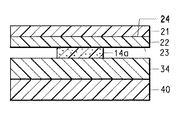
図2に示される受容体要素(20)は、レーザー適性集成体の第2の部分であり、ここに供与体の露光領域から物質が転写される。転写させることのできる特定の物質は、バインダー組成物と顔料とを含む着色材である。本発明の受容体要素は、画像受容層(22)を形成すべく先に記載したような配合物を含む。 The receiver element (20) shown in FIG. 2 is the second part of the laser-compatible assembly into which material is transferred from the exposed area of the donor. A specific material that can be transferred is a colorant comprising a binder composition and a pigment. The receiver element of the present invention comprises a formulation as described above to form an image receiving layer (22).
ほとんどの場合、供与体層の露光領域は、受容体要素の不在下では、供与体要素から除去されないであろう。すなわち、供与体要素だけをレーザー放射線で露光しても、物質の除去または転写は起こらない。供与体層の露光領域は、レーザー放射線で露光すると、供与体要素から除去されて、隣接する受容体要素に転写される。好ましい実施形態では、供与体要素を実際に受容体要素に接触させる。 In most cases, the exposed areas of the donor layer will not be removed from the donor element in the absence of the receiver element. That is, exposure of only the donor element with laser radiation does not result in removal or transfer of material. The exposed area of the donor layer is removed from the donor element and transferred to an adjacent receiver element upon exposure to laser radiation. In a preferred embodiment, the donor element is actually contacted with the acceptor element.
受容体要素(20)は、非感光性であってもまたは感光性であってもよい。非感光性受容体要素は、好ましくは、受容体支持体(21)と、画像受容表面(23)および非画像受容境界面(24)を有する画像受容層(22)とを含む。受容体支持体(21)は、典型的には、寸法安定性シート材料を含む。支持体が透過性である場合、受容体支持体を介して集成体を画像化することができる。受容体支持体用の透過性フィルムの例としては、たとえば、ポリエチレンテレフタレート、ポリエーテルスルホン、ポリイミド、ポリ(ビニルアルコール−co−アセタール)、ポリエチレン、または酢酸セルロースのようなセルロースエステルが挙げられる。不透過性支持体材料の例としては、たとえば、二酸化チタンのような白色顔料が充填されたポリエチレンテレフタレート、アイボリー紙、またはタイベック(Tyvek)(登録商標)スパンボンドポリオレフィンのような合成紙が挙げられる。プルーフィング用途では、紙支持体が典型的かつ好適であり、一方、医療用ハードコピーおよびカラーフィルターアレイ用途では、ポリ(エチレンテレフタレート)のようなポリエステル支持体が典型的かつ好適である。粗面化された支持体を受容体要素中で使用することも可能である。 The receiver element (20) may be non-photosensitive or photosensitive. The non-photosensitive receiver element preferably comprises a receiver support (21) and an image receiving layer (22) having an image receiving surface (23) and a non-image receiving interface (24). The receiver support (21) typically comprises a dimensionally stable sheet material. If the support is permeable, the assembly can be imaged through the receptor support. Examples of permeable films for receptor supports include, for example, polyethylene terephthalate, polyethersulfone, polyimide, poly (vinyl alcohol-co-acetal), polyethylene, or cellulose esters such as cellulose acetate. Examples of impermeable support materials include, for example, polyethylene terephthalate filled with a white pigment such as titanium dioxide, ivory paper, or synthetic paper such as Tyvek® spunbond polyolefin. . For proofing applications, a paper support is typical and preferred, while for medical hardcopy and color filter array applications, a polyester support such as poly (ethylene terephthalate) is typical and preferred. It is also possible to use a roughened support in the receiver element.
先に記載したような画像受容層(22)の配合物に加えて、画像受容層は、ポリカーボネート、ポリウレタン、ポリエステル、ポリビニルクロリド、スチレン/アクリロニトリル、エチレンおよび/またはビニルクロリドとの酢酸ビニルコポリマー、または(メタ)アクリレート(たとえば、ブチルメタクリレート)ポリマーおよびそのコポリマーのような1つ以上の高分子成分を含みうる。 In addition to the formulation of the image-receiving layer (22) as described above, the image-receiving layer may be a polycarbonate, polyurethane, polyester, polyvinyl chloride, styrene / acrylonitrile, vinyl acetate copolymer with ethylene and / or vinyl chloride, or One or more polymeric components such as (meth) acrylate (eg, butyl methacrylate) polymers and copolymers thereof may be included.
他の有用な受容体要素成分はまた、米国特許公報(特許文献24)にも開示されている。 Other useful receptor element components are also disclosed in US Pat.
画像受容層のこのコーティング重量は、画像を受容するのに有効な任意の量でありうる。一般的には10〜150mg/dm2、好ましくは40〜60mg/dm2の範囲のコーティング重量で、好結果が得られている。画像受容層は、典型的には、テクスチャーを形成するように適用してから除去されるポリエチレンのようなテクスチャードフィルムを用いてエンボス加工することにより、粗面化させることが可能である。粗面化テクスチャーはまた、配合物中に粗面化剤を含有させることにより形成することも可能である。 This coating weight of the image receiving layer can be any amount effective to receive the image. In general, good results have been obtained with coating weights in the range of 10 to 150 mg / dm 2 , preferably 40 to 60 mg / dm 2 . The image-receiving layer can typically be roughened by embossing with a textured film such as polyethylene that is applied to form a texture and then removed. A roughening texture can also be formed by including a roughening agent in the formulation.
画像受容層に加えて、受容体要素は、場合により、受容体支持体と画像受容層との間に1層以上の他の層(図示せず)を含みうる。画像受容層と支持体との間の追加層は、剥離層である。露光時および供与体要素からの分離時には、画像受容層は受容体支持体に固着するが、ラミネーションなどによるパーマネント基材または支持体への画像受容層の転写時には、受容体支持体からの画像受容層の分離を促進するように、剥離層は、受容体支持体に所望の固着性バランスを提供することができる。剥離層として使用するのに好適な材料の例としては、ポリアミド、シリコーン、ビニルクロリドポリマーおよびコポリマー、ビニルアセテートポリマーおよびコポリマー、ならびに可塑化ポリビニルアルコールが挙げられる。剥離層は、1〜50ミクロンの範囲の厚さを有しうる。受容体要素中に、典型的には、剥離層と受容体支持体との間に、変形可能な層であるクッション層を存在させることも可能である。クッション層は、集成時に受容体要素と供与体要素との間の接触を増大させるべく、存在させうる。クッション層として使用するのに好適な材料の例としては、スチレンとオレフィンモノマーとのコポリマー、たとえば、スチレン/エチレン/ブチレン/スチレンブロックコポリマー、スチレン/ブチレン/スチレンブロックコポリマーが挙げられる。フレキソグラフィープレート用途でバインダーとして有用なエラストマーは、この目的にも有用でありうる。 In addition to the image receiving layer, the receiver element may optionally include one or more other layers (not shown) between the receiver support and the image receiving layer. An additional layer between the image receiving layer and the support is a release layer. During exposure and separation from the donor element, the image receiving layer adheres to the receiver support, but during transfer of the image receiving layer to a permanent substrate or support, such as by lamination, image reception from the receiver support. The release layer can provide a desired balance of adhesion to the receiver support so as to facilitate layer separation. Examples of materials suitable for use as the release layer include polyamides, silicones, vinyl chloride polymers and copolymers, vinyl acetate polymers and copolymers, and plasticized polyvinyl alcohol. The release layer can have a thickness in the range of 1-50 microns. In the receiver element, a cushion layer, typically a deformable layer, can also be present between the release layer and the receiver support. A cushion layer may be present to increase contact between the receiver element and the donor element during assembly. Examples of suitable materials for use as the cushion layer include copolymers of styrene and olefin monomers such as styrene / ethylene / butylene / styrene block copolymers, styrene / butylene / styrene block copolymers. Elastomers useful as binders in flexographic plate applications can also be useful for this purpose.
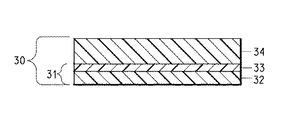
図3に示される画像固定要素(30)を利用することも可能である。画像固定要素は、剥離表面(31)を有する支持体と、熱可塑性ポリマー層(34)とを含む。 It is also possible to use the image fixing element (30) shown in FIG. The image fixing element includes a support having a release surface (31) and a thermoplastic polymer layer (34).
剥離表面(31)を有する支持体は、支持体(32)と、剥離層であってもよいオプションの層(33)とを含みうる。支持体(32)として使用される材料が、本質的に、剥離可能な表面を有する場合、たとえば、ポリエチレンまたはフルオロポリマーの場合、追加の表面層は必要でない。表面層または剥離層(33)は、支持体(32)に対して、本発明の処理工程全体にわたり支持体に固着した状態を保持するのに十分な固着性を有していなければならない。適正な剛性および寸法安定性を有するほとんど任意の材料が支持体(32)として有用である。有用な支持体(32)のいくつかの例としては、ポリエチレンテレフタレートおよびポリエチレンナフタネートなどのポリエステル、ポリアミド、ポリカーボネート、フルオロポリマー、ポリアセタール、ポリオレフィンなどのような高分子フィルムが挙げられる。支持体(32)はまた、薄い金属シートであってもよいしまたは天然もしくは合成の紙基材であってもよい。支持体(32)は、透過性であっても半透過性であってもまたは不透過性であってもよく、着色されていてもよく、さらに、カラー画像を含有する受容体要素へのそのラミネーション時にラミネーションデバイスを通る画像固定要素の移動を支援するための充填剤のような添加剤を組み入れてもよい。 The support having a release surface (31) can include a support (32) and an optional layer (33) which can be a release layer. If the material used as support (32) has an essentially peelable surface, for example in the case of polyethylene or fluoropolymer, no additional surface layer is necessary. The surface layer or release layer (33) must have sufficient adherence to the support (32) to keep it attached to the support throughout the processing steps of the present invention. Almost any material with proper stiffness and dimensional stability is useful as the support (32). Some examples of useful supports (32) include polymeric films such as polyesters such as polyethylene terephthalate and polyethylene naphthalate, polyamides, polycarbonates, fluoropolymers, polyacetals, polyolefins, and the like. The support (32) may also be a thin metal sheet or a natural or synthetic paper substrate. The support (32) may be transmissive, translucent or impermeable, colored, and further to its receiver element containing a color image. Additives such as fillers may be incorporated to assist in moving the image fixing element through the lamination device during lamination.
支持体(32)は、片面または両面上にコーティングされた帯電防止層を有していてもよい。これは、支持体(32)を熱可塑性ポリマー層(34)から取り除くときに静電気を減少させるのに有用でありうる。一般的には、支持体(32)のバック面上(すなわち、熱可塑性ポリマー層(34)から離れた支持体の面上)にコーティングされた帯電防止層を有することが好ましい。帯電防止材として使用しうる物質は、当技術分野で周知である。場合により、支持体(32)はまた、画像固定要素の輸送および取扱いを支援すべくマットテクスチャーを有していてもよい。 The support (32) may have an antistatic layer coated on one or both sides. This can be useful for reducing static electricity when the support (32) is removed from the thermoplastic polymer layer (34). In general, it is preferred to have an antistatic layer coated on the back side of the support (32) (ie on the side of the support remote from the thermoplastic polymer layer (34)). Materials that can be used as antistatic materials are well known in the art. Optionally, the support (32) may also have a mat texture to assist in the transport and handling of the image fixing element.
支持体(32)の剥離表面は、表面層(33)により提供しうる。剥離層は、一般的には、層の分離を促進する非常に薄い層である。剥離層として有用な材料は、当技術分野で周知であり、たとえば、シリコーン、メラミンアクリル樹脂、ビニルクロリドポリマーおよびコポリマー、ビニルアセテートポリマーおよびコポリマー、可塑化ポリビニルアルコール、エチレンおよびプロピレンのポリマーおよびコポリマーなどが挙げられる。個別の剥離層を支持体上にコーティングする場合、層は、一般的には、0.5〜10マイクロメートルの範囲の厚さを有する。 The release surface of the support (32) can be provided by the surface layer (33). The release layer is generally a very thin layer that facilitates layer separation. Materials useful as release layers are well known in the art and include, for example, silicones, melamine acrylic resins, vinyl chloride polymers and copolymers, vinyl acetate polymers and copolymers, plasticized polyvinyl alcohol, ethylene and propylene polymers and copolymers, and the like. Can be mentioned. When a separate release layer is coated on the support, the layer generally has a thickness in the range of 0.5 to 10 micrometers.
剥離層(33)は、静電防止剤、着色材、ハレーション防止染料、蛍光増白剤、界面活性剤、可塑剤、コーティング助剤、マット化剤などのような物質を含んでいてもよい。 The release layer (33) may contain substances such as antistatic agents, colorants, antihalation dyes, fluorescent brighteners, surfactants, plasticizers, coating aids, matting agents and the like.
熱可塑性ポリマー層(34)の熱可塑性ポリマーは、好ましくは、アモルファス(すなわち、非結晶性)の特性をもち、高軟化点、中〜高分子量、および画像受容ポリマー層の成分(たとえば、ポリカプロラクトン)との相溶性を有する。さらに、亀裂を生じることがなくしかも多くの異なるパーマネント基材に接合される能力を有する可撓性は有利である。ポリマーは、好ましくは、溶媒に可溶であり、溶媒および光に対して良好な安定性を有し、かつ良好な皮膜形成剤である。 The thermoplastic polymer of the thermoplastic polymer layer (34) preferably has amorphous (ie, non-crystalline) properties, high softening point, medium to high molecular weight, and components of the image receiving polymer layer (eg, polycaprolactone). ). In addition, flexibility is advantageous which does not cause cracking and has the ability to be bonded to many different permanent substrates. The polymer is preferably soluble in a solvent, has good stability to solvent and light, and is a good film former.
多くの有用な熱可塑性ポリマー材料が存在する。本発明に使用するのに好ましいのは、約27〜150℃、好ましくは40〜70℃、より好ましくは45〜55℃の範囲のTg(ガラス転移温度)、比較的高い軟化点(たとえば、47℃のTg、142℃のメルトフロー)、ASTM D822Aにより決定したときの低い破断点伸び(たとえば、3)、および中程度の重量平均分子量(Mw)(たとえば、67,000の領域)を有する熱可塑性ポリマーである。たとえば、約47℃のTgを有するポリエステルポリマーが好ましい。なぜなら、画像受容ポリマー(たとえば、結晶性ポリカプロラクトン)と画像固定層中のポリエステルポリマーとの間の良好な相溶性が達成されるからである。しかしながら、他の好適なポリマーは、許容しうる結果を与えることが示されている。いくつかの好適なポリマーとしては、メタクリレート/アクリレート、ポリビニルアセテート、ポリビニルブチラール、ポリビニルホルマール、スチレン−イソプレン−スチレンポリマー、およびスチレン−エチレン−ブチレン−スチレンポリマーなどが挙げられる。 There are many useful thermoplastic polymer materials. Preferred for use in the present invention is a Tg (glass transition temperature) in the range of about 27-150 ° C, preferably 40-70 ° C, more preferably 45-55 ° C, a relatively high softening point (eg 47 ° C Tg, 142 ° C melt flow), low elongation at break as determined by ASTM D822A (eg, 3), and moderate weight average molecular weight (Mw) (eg, region of 67,000) It is a plastic polymer. For example, a polyester polymer having a Tg of about 47 ° C. is preferred. This is because good compatibility is achieved between the image receiving polymer (eg, crystalline polycaprolactone) and the polyester polymer in the image fixing layer. However, other suitable polymers have been shown to give acceptable results. Some suitable polymers include methacrylate / acrylate, polyvinyl acetate, polyvinyl butyral, polyvinyl formal, styrene-isoprene-styrene polymer, and styrene-ethylene-butylene-styrene polymer.
熱可塑性ポリマーは、熱可塑性ポリマー層成分の全重量を基準にして、約60〜90%、好ましくは約70〜85%の量で存在する。 The thermoplastic polymer is present in an amount of about 60-90%, preferably about 70-85%, based on the total weight of the thermoplastic polymer layer component.
熱可塑性ポリマー層および画像受容層は、パーマネント基材(たとえば、紙)へのラミネーション時および冷却時に有意に移動しないようにプロセス時に画像がそれらの間に挟置されるようになるという点で、互いに関連している。これにより、この方式で(すなわち、画像固定要素で)熱可塑性ポリマー層を利用しない類似の方法と比較して、ハーフトーンドットの移動、スワス境界の亀裂および合体が、有意に減少し、それらは、かろうじて認知できるかまたは実質的に取り除かれる。 The thermoplastic polymer layer and the image receiving layer will be sandwiched between them during the process so that they do not move significantly during lamination to the permanent substrate (e.g. paper) and during cooling, Are related to each other. This significantly reduces halftone dot migration, swath boundary cracking and coalescence, as compared to similar methods that do not utilize thermoplastic polymer layers in this manner (ie, with image fixing elements). Barely perceivable or substantially eliminated.
熱可塑性ポリマー層はまた、パーマネント基材に転写されたカラー画像中のNIR染料に関連づけられる最終カラーへの影響を減少させる漂白化学過程を導入するためのビヒクルまたは機構を提供する。 The thermoplastic polymer layer also provides a vehicle or mechanism for introducing a bleaching chemistry process that reduces the effect on the final color associated with the NIR dye in the color image transferred to the permanent substrate.
熱可塑性ポリマー層はまた、この層の機能を妨害しないかぎり、添加剤を含有しうる。たとえば、可塑剤、他の変性用ポリマー、コーティング助剤、界面活性剤のような添加剤を使用することができる。いくつかの有用な可塑剤としては、ポリエチレングリコール、ポリプロピレングリコール、フタル酸エステル、ジブチルフタレート、およびトリアセチンのようなグリセリン誘導体が挙げられる。好ましくは、可塑剤は、熱可塑性ポリマー層成分の全重量を基準にして、約1〜20%、最も好ましくは5〜15%の量で存在する。 The thermoplastic polymer layer may also contain additives so long as they do not interfere with the function of this layer. For example, additives such as plasticizers, other modifying polymers, coating aids, surfactants can be used. Some useful plasticizers include polyethylene glycol, polypropylene glycol, phthalate esters, dibutyl phthalate, and glycerin derivatives such as triacetin. Preferably, the plasticizer is present in an amount of about 1-20%, most preferably 5-15%, based on the total weight of the thermoplastic polymer layer component.
先に述べたように、熱可塑性ポリマー層はまた、好ましくは、NIR染料のような熱増幅添加剤を漂白するための1種以上の染料漂白剤を含有しうる。染料漂白剤は、供与体要素中および/または受容体要素中に存在させうる。いくつかの有用な漂白剤としては、アミン、アゾ化合物、カルボニル化合物、および有機金属化合物、ならびにカルボアニオンが挙げられる。有用な酸化剤としては、ペルオキシド、ジアシルペルオキシド、過酸、ヒドロペルオキシド、ペルスルフェート、N−ハロアミド、N−ハロイミド、およびハロゲン化合物が挙げられる。ポリメチン型NIR染料と併用されるとりわけ好ましい染料漂白剤は、過酸化水素、有機ペルオキシド、ヘキサアリールビイミダゾール、N−ハロゲン化スクシンイミド、N−ハロゲン化およびビス−N−ハロゲン化ヒダントイン、他のハロゲン化有機化合物、ペルスルフェート、ペルボレート、ペルホスフェート、ヒポクロリット、およびアゾ化合物よりなる群から選択されるものである。ハロゲン化漂白剤では、ハロゲンは、元素の周期表(Periodic Table of the Elements)(サージェント・ウェルチ・サイエンティフィック・カンパニー(Sargent−Welch Scientific Company)1979年)に記載の第VIIB族の任意の元素でありうるが、典型的には、塩素、臭素、またはフッ素である。 As previously mentioned, the thermoplastic polymer layer may also preferably contain one or more dye bleaches for bleaching thermal amplification additives such as NIR dyes. Dye bleaching agents can be present in the donor element and / or in the receiver element. Some useful bleaching agents include amines, azo compounds, carbonyl compounds, and organometallic compounds, and carbanions. Useful oxidizing agents include peroxides, diacyl peroxides, peracids, hydroperoxides, persulfates, N-haloamides, N-haloimides, and halogen compounds. Particularly preferred dye bleaches for use with polymethine-type NIR dyes are hydrogen peroxide, organic peroxides, hexaarylbiimidazoles, N-halogenated succinimides, N-halogenated and bis-N-halogenated hydantoins, other halogenated One selected from the group consisting of organic compounds, persulfates, perborates, perphosphates, hypochlorites, and azo compounds. In halogenated bleaching agents, halogen is any element of Group VIIB described in Periodic Table of the Elements (Sargent-Welch Scientific Company, 1979). Typically, it is chlorine, bromine, or fluorine.
染料漂白剤は、熱可塑性ポリマー層成分の全重量を基準にして、通常は約1〜約20%、好ましくは約5〜約15%の量で存在する。 The dye bleach is usually present in an amount of about 1 to about 20%, preferably about 5 to about 15%, based on the total weight of the thermoplastic polymer layer components.
着色画像を受容するためのパーマネント基材は、ほとんど任意の所望の材料から選択することができる。ほとんどのプルーフィング用途では、紙支持体が使用され、好ましくは、画像が最終的に印刷されるのと同一の紙が使用される。パーマネント基材として使用しうる他の材料としては、布、木材、ガラス、陶磁器、ほとんどの高分子フィルム、合成紙、薄い金属シート、またはフォイルなどが挙げられる。熱可塑性ポリマー層(34)に固着するほとんど任意の材料をパーマネント基材として使用することができる。カラーフィルター用途では、パーマネント基材は、典型的には、ガラスである。 The permanent substrate for receiving the colored image can be selected from almost any desired material. In most proofing applications, a paper support is used, preferably the same paper on which the image is finally printed. Other materials that can be used as the permanent substrate include cloth, wood, glass, ceramics, most polymer films, synthetic paper, thin metal sheets, or foils. Almost any material that adheres to the thermoplastic polymer layer (34) can be used as a permanent substrate. For color filter applications, the permanent substrate is typically glass.
本発明の方法の第1の工程は、たとえば、図4に示されるように、レーザー放射線でレーザー適性集成体を画像様に露光することである。露光工程は、好ましくは約600mJ/cm2以下、最も好ましくは約250〜440mJ/cm2のレーザーフルエンスで行われる。レーザー適性集成体は、供与体要素と受容体要素とを含む。 The first step of the method of the present invention is to imagewise expose the laser-compatible assembly with laser radiation, for example as shown in FIG. The exposure step is preferably performed at a laser fluence of about 600 mJ / cm 2 or less, most preferably about 250 to 440 mJ / cm 2 . The laser suitability assembly includes a donor element and an acceptor element.
通常、集成体は、カバーシートが存在するのであればそれを取り除いた後、好ましくは供与体層が受容体要素上の画像受容層に実際に接触するように、供与体要素を受容体要素に隣接させて配置することにより、作製される。これを図4に示す。真空および/または圧力を用いて、2つの要素を保持一体化させることができる。そのほか、供与体層または画像受容層の中でスペーサー粒子を使用して、供与体要素と受容体要素とをわずかに離間させて配置することも可能である。一選択肢として、周囲で層を融合させることにより、供与体要素と受容体要素とを保持一体化させることができる。他の選択肢として、供与体と受容体要素とをテープ留めで一体化して画像形成装置にテープ留めすることができるか、またはピン/クランピングシステムを使用することができる。さらに他の選択肢として、供与体要素を受容体要素にラミネートしてレーザー適性集成体を形成することができる。レーザー適性集成体は、レーザー画像形成を容易に行えるように、ドラム上に都合よく装着することができる。 Usually, the assembly will have the donor element attached to the receiver element, preferably after the cover sheet is removed, so that the donor layer is actually in contact with the image receiving layer on the receiver element. It is produced by arranging them adjacent to each other. This is shown in FIG. The two elements can be held together using vacuum and / or pressure. Alternatively, it is possible to use spacer particles in the donor layer or the image receiving layer to place the donor element and the receiver element slightly spaced apart. As an option, the donor and acceptor elements can be held together by fusing layers around them. As another option, the donor and receiver elements can be taped together and taped to the imaging device, or a pin / clamping system can be used. As yet another option, the donor element can be laminated to the receiver element to form a laser-compatible assembly. The laser-compatible assembly can be conveniently mounted on the drum to facilitate laser imaging.
種々のタイプのレーザーを用いて、レーザー適性集成体を露光することができる。レーザーは、好ましくは、赤外領域、近赤外領域、または可視領域で発光するレーザーである。とりわけ有利であるのは、750〜870nmの領域で発光するダイオードレーザーであり、これは、小サイズ、低コスト、安定性、信頼性、丈夫さ、および変調の容易さの点で実質的な利点を提供する。780〜850nmの範囲で発光するダイオードレーザーが最も好ましい。そのようなレーザーは、たとえば、スペクトラ・ダイオード・ラボラトリーズ(Spectra Diode Laboratories)(カリフォルニア州サンノゼ(San Jose,CA))から入手可能である。 Various types of lasers can be used to expose the laser suitability assembly. The laser is preferably a laser that emits light in the infrared region, near infrared region, or visible region. Particularly advantageous is a diode laser emitting in the 750-870 nm region, which is a substantial advantage in terms of small size, low cost, stability, reliability, robustness, and ease of modulation. I will provide a. A diode laser emitting light in the range of 780 to 850 nm is most preferable. Such lasers are available from, for example, Spectra Diode Laboratories (San Jose, Calif.).
露光は、供与体要素の可撓性エジェクション層を介してまたは受容体要素を介して、行うことができる。ただし、これらは、レーザー放射線を実質的に透過するものでなければならない。ほとんどの場合、供与体可撓性エジェクション層は、赤外線を透過するフィルムであろう。そして露光は、可撓性エジェクション層またはサビング層を介して都合よく行われる。しかしながら、受容体要素が赤外線を実質的に透過する場合、赤外線レーザー放射線で受容体要素を画像様に露光することにより、本発明の方法を行うこともできる。 The exposure can take place via the flexible ejection layer of the donor element or via the receiver element. However, they must be substantially transparent to laser radiation. In most cases, the donor flexible ejection layer will be an infrared transparent film. The exposure is conveniently performed through a flexible ejection layer or a subbing layer. However, if the receiver element is substantially transparent to infrared radiation, the method of the present invention can also be carried out by exposing the receiver element imagewise with infrared laser radiation.
供与体層の露光領域が受容体要素にパターン状に転写されるように、レーザー適性集成体を画像様に露光する。パターンそれ自体は、たとえば、コンピューターにより生成されるドットまたは線画の形態で、コピー対象のアートワークを走査するにより得られる形態で、もとのアートワークから得られるディジタル化画像の形態で、またはレーザー露光の前にコンピューターで電子的に組み合わせることのできるこれらの形態の任意の組合せで、ありうる。レーザービームとレーザー適性集成体は、集成体の各微小領域(すなわち、「ピクセル」)がレーザーにより個別にアドレス指定されるように、互いに一定した移動状態にある。これは、一般的には、レーザー適性集成体を回転可能なドラムに取り付けることにより、達成される。フラットベッドレコーダーを使用することもできる。 The laser-compatible assembly is imagewise exposed so that the exposed areas of the donor layer are transferred in a pattern to the receiver element. The pattern itself is, for example, in the form of a computer-generated dot or line drawing, obtained by scanning the artwork to be copied, in the form of a digitized image obtained from the original artwork, or laser It can be any combination of these forms that can be combined electronically with a computer prior to exposure. The laser beam and the laser-compatible assembly are in constant motion relative to each other such that each microregion (ie, “pixel”) of the assembly is individually addressed by the laser. This is generally accomplished by attaching the laser-compatible assembly to a rotatable drum. A flatbed recorder can also be used.
本発明の方法の次の工程は、受容体要素から供与体要素を分離させることである。通常、これは、単純に2つの要素を剥離することにより行われる。これは、一般的には、ごくわずかの剥離力を必要とし、受容体要素から単純に供与体要素支持体を分離させることにより、達成される。これは、任意の従来の分離技術を用いて行うことができ、手動でまたはオペレーターを介在させることなく自動で行いうる。 The next step in the process of the present invention is to separate the donor element from the acceptor element. This is usually done by simply peeling the two elements. This is generally achieved by requiring very little peel force and simply separating the donor element support from the receiver element. This can be done using any conventional separation technique and can be done manually or automatically without operator intervention.
図5に示されるように、レーザーで生成されたカラー画像(着色画像としても知られる)の形で、好ましくは、ハーフトーンドット画像の形で、分離が行われ、該画像は、受容体要素の画像受容層上に出現する供与体層の転写された露光領域を含む。好ましくは、露光工程および分離工程により形成された画像は、レーザーで生成されて受容体支持体の層上に形成されたハーフトーンドットカラー画像である。 As shown in FIG. 5, the separation is performed in the form of a laser-generated color image (also known as a colored image), preferably in the form of a halftone dot image, the image being a receptor element. Including a transferred exposed area of the donor layer appearing on the image receiving layer. Preferably, the image formed by the exposure step and the separation step is a halftone dot color image generated with a laser and formed on the layer of the receiver support.
画像固定要素を使用する場合、次に、画像固定要素の熱可塑性ポリマー層と受容体要素の画像受容層との間に画像を挟置した状態で、画像固定要素を画像受容体要素に接触させる(好ましくは、ラミネートする)。典型的には、熱可塑性ポリマー層は、画像に接触した状態である。これは、図6に最も良好に示されている。好ましくは、本願特許出願人により製造されているウォータープルーフ(登録商標)ラミネーター(WATERPROOF(登録商標) Laminator)を用いてラミネーションを達成する。しかしながら、他の従来の手段を用いて、画像を有する受容体要素と固定要素の熱可塑性ポリマー層との組合せを達成することも可能である。熱可塑性ポリマー層(34)に対する、剥離表面(31)を有する固定要素支持体の固着性は、サンドイッチ体における他のいかなる層間の固着性よりも小さいことが重要である。 If an image fixing element is used, the image fixing element is then brought into contact with the image receiver element with the image sandwiched between the thermoplastic polymer layer of the image fixing element and the image receiving layer of the receiver element. (Preferably, laminate). Typically, the thermoplastic polymer layer is in contact with the image. This is best shown in FIG. Preferably, lamination is achieved using a Waterproof® Laminator manufactured by the present patent applicant (WATERPROOF® Laminator). However, it is also possible to use other conventional means to achieve a combination of image-receiving receiver element and fixing element thermoplastic polymer layer. It is important that the anchoring of the anchoring element support having the release surface (31) to the thermoplastic polymer layer (34) is less than the anchoring between any other layers in the sandwich.
その後、図6Aに示されるように、剥離表面(33)を有する支持体(32)を取り除いて(好ましくは、剥離して)熱可塑性フィルムを露出させる。その後、パーマネント基材を画像固定層(もし使用するのであれば)の露出した熱可塑性ポリマー層に、または画像固定層を用いる場合について図6Aに示されたサンドイッチ体の画像受容要素の画像受容層に、接触させることにより(好ましくは、ラミネートすることにより)、受容体要素上のカラー画像をパーマネント基材に転写することができる。この場合にもまた、好ましくは、本願特許出願人により製造されているウォータープルーフ(登録商標)ラミネーター(WATERPROOF(登録商標) Laminator)を用いてラミネーションを達成する。しかしながら、他の従来の手段を用いて、図7に示されるサンドイッチ体を生じるこの接触を達成することも可能である。 Thereafter, as shown in FIG. 6A, the support (32) having a release surface (33) is removed (preferably peeled) to expose the thermoplastic film. The permanent substrate is then applied to the exposed thermoplastic polymer layer of the image fixing layer (if used) or to the image receiving layer of the sandwich image receiving element shown in FIG. 6A for the case of using an image fixing layer. The color image on the receiver element can be transferred to a permanent substrate by contact (preferably by lamination). Again, lamination is preferably achieved using a Waterproof® Laminator manufactured by the applicant of the present patent application (WATERPROOF® Laminator). However, other conventional means may be used to achieve this contact resulting in the sandwich shown in FIG.
他の実施形態は、受容体支持体(21)を取り除いて(好ましくは、剥離して)図8に示される集成体またはサンドイッチ体を形成する追加の工程を含む。好ましい実施形態では、図7および8に例示された集成体は、レーザーで生成されて結晶性ポリマー層上に形成されたハーフトーンドットカラー熱画像と、一表面が該結晶性ポリマー層にラミネートされ、他の表面がパーマネント基材にラミネートされた熱可塑性ポリマー層とを含み、それにより、カラー画像が結晶性ポリマー層と熱可塑性ポリマー層との間に挟置された印刷プルーフを表す。 Other embodiments include the additional step of removing (preferably peeling) the receptor support (21) to form the assembly or sandwich shown in FIG. In a preferred embodiment, the assembly illustrated in FIGS. 7 and 8 comprises a laser-generated halftone dot color thermal image formed on a crystalline polymer layer and one surface laminated to the crystalline polymer layer. A printing proof in which the other surface includes a thermoplastic polymer layer laminated to a permanent substrate, whereby the color image is sandwiched between the crystalline polymer layer and the thermoplastic polymer layer.
受容体支持体(21)を取り除くと、画像受容層(22)の非画像受容境界面(24)が、新しい表面として環境に露出される。本発明の配合物の1つの利点は、プロセス時または最終物品に関して、受容層が新しい表面として環境に露出されたとき、それが耐久性、ブロッキング抵抗性、および透過性をもつ点である。 When the receiver support (21) is removed, the non-image receiving interface (24) of the image receiving layer (22) is exposed to the environment as a new surface. One advantage of the formulations of the present invention is that when the receiving layer is exposed to the environment as a new surface, either during processing or with respect to the final article, it is durable, blocking resistant, and permeable.
プルーフィング用途では、受容体要素は、マルチカラー画像が形成される中間要素でありうる。第1の着色材を含む供与体層を有する供与体要素は、先に記載したように、露光され分離される。受容体要素は、第1の着色材で形成された着色画像を有する。この画像は、好ましくは、レーザーで生成されたハーフトーンドットカラー熱画像である。その後、第1の供与体要素のものとは異なる供与体層を有する第2の供与体要素を、第1の着色材の着色画像を有する受容体要素と合わせて、レーザー適性集成体を形成し、先に記載したように、画像様に露光し、分離させる。(a)前に使用したものとは異なる着色材を有する供与体要素と、あらかじめ画像化された受容体要素とを合わせて、レーザー適性集成体を形成する工程、(b)露光する工程、および(c)分離させる工程は、受容体要素上にカラープルーフの多色画像を構築するために必要なだけ逐次的に繰り返される。 For proofing applications, the receiver element can be an intermediate element on which a multicolor image is formed. A donor element having a donor layer comprising a first colorant is exposed and separated as described above. The receiver element has a colored image formed with the first colorant. This image is preferably a laser generated halftone dot color thermal image. Thereafter, a second donor element having a donor layer different from that of the first donor element is combined with a receiver element having a colored image of the first colorant to form a laser-compatible assembly. , Imagewise exposed and separated as described above. (A) combining a donor element having a different colorant from that previously used and a pre-imaged receiver element to form a laser-compatible assembly; (b) exposing; and (C) The separating step is iteratively repeated as necessary to build a color proof multicolor image on the receiver element.
その後、固定要素をもし使用するのであれば、最終的着色画像を熱可塑性ポリマー層に接触させた状態で、固定要素を画像受容要素上の複数の着色画像に接触させる(好ましくは、ラミネートする)。 Thereafter, if a fixing element is to be used, the fixing element is contacted (preferably laminated) with a plurality of colored images on the image receiving element, with the final colored image in contact with the thermoplastic polymer layer. .
本発明の方法をカラーフィルターの作製に利用する場合、顔料は、通常、透過性であり、画像は、米国特許公報(特許文献25)および米国特許公報(特許文献26)に開示されているものを含めてカラーフィルター技術分野で周知の方法により、導電性層に関連づけられる。 When the method of the present invention is used for the production of a color filter, the pigment is usually transparent, and the image is disclosed in US Patent Publication (Patent Document 25) and US Patent Publication (Patent Document 26). Are associated with the conductive layer by methods well known in the color filter art.
典型的には、本発明の画像受容層、および本発明の画像受容層を使用する方法は、さまざまな用途における他のタイプの物質の転写にも同じようにあてはまる。たとえば、画像転写要素を用いて、典型的には液晶ディスプレイデバイスおよびフラットパネルディスプレイの作製に使用されるカラーフィルターを作製する場合にもあてはまる。一般的には、本発明の範囲は、固体物質が受容体にパターン状に適用される任意の用途を包含するように意図される。 Typically, the image-receiving layer of the present invention and the methods using the image-receiving layer of the present invention apply equally well to the transfer of other types of materials in various applications. This is also the case, for example, when using image transfer elements to make color filters typically used in making liquid crystal display devices and flat panel displays. In general, the scope of the present invention is intended to encompass any application where a solid material is applied in a pattern to a receptor.
本発明の1つの用途は、モノクロームフィルターまたはカラーフィルターのような放射フィルターの作製である。放射フィルターは、フラットパネルディスプレイ、液晶ディスプレイ、有機発光ダイオードにより照明されるディスプレイ、およびプラズマ法により照明されるディスプレイのようなディスプレイで使用することができる。ディスプレイは、単色(モノクローム)、または白色、黒色、および灰色を含めて多色(たとえば、赤色、緑色、および青色)を表示しうる。 One application of the present invention is the production of radiation filters such as monochrome filters or color filters. The radiation filter can be used in displays such as flat panel displays, liquid crystal displays, displays illuminated by organic light emitting diodes, and displays illuminated by the plasma method. The display may display a single color (monochrome) or multiple colors (eg, red, green, and blue) including white, black, and gray.
本発明の顔料着色層でパターン化された物品は、フラットパネルディスプレイのような液晶ディスプレイデバイスで使用することができる。液晶ディスプレイデバイスは、一般的には、液晶材料が充填されるキャビティーを規定する2つの離間して配置された部分的にまたは完全に透過性のパネルを備える。部分的に透過性の1つのパネルは、本発明のモノクロームまたはカラーの放射フィルターを備えうるか、または放射フィルターは、2つのパネルに関連づけて配向させることができる。アクティブ駆動液晶ディスプレイデバイスでは、一方の透過性パネル上に透過性電極を形成することが可能であり(この電極はパターン化されていてもされていなくてもよい)、他方の透過性パネル上には、個別にアドレス指定可能な透過性電極が形成される。配向層は、両方のパネル上の透過性電極層を覆うように設けられ、パネル間にツイスト(たとえば、90度のツイスト)を導入すべく液晶分子を配向させるように処理される。したがって、1つのタイプのディスプレイでは、平面偏光光の偏光面は、セルの一方の表面から他方の表面へツイステッド液晶組成物を透過するときに、90度の角度で回転されるであろう。ツイステッドネマティックおよびスーパーツイステッドネマティックのような配向を使用することができる。セルの所定の電極間に電界を印加すると、所定の電極間のセルの一部分で一時的に液晶組成物の配向ツイストが破壊され、それにより、液晶組成物を透過する光の偏光変化が変化する。セルの両側で光学偏光子を用いることにより、電界が印加されたか否に応じて、偏光光は、セルを完全にもしくは部分的に透過したり、または消失したりしうる。 Articles patterned with the pigmented layer of the present invention can be used in liquid crystal display devices such as flat panel displays. Liquid crystal display devices typically comprise two spaced apart partially or fully transmissive panels that define a cavity filled with liquid crystal material. One partially transmissive panel can comprise the monochrome or color emission filter of the present invention, or the emission filter can be oriented relative to the two panels. In an active drive liquid crystal display device, it is possible to form a transmissive electrode on one transmissive panel (this electrode may or may not be patterned) and on the other transmissive panel Are formed with individually addressable transparent electrodes. An alignment layer is provided to cover the transmissive electrode layer on both panels and is processed to align the liquid crystal molecules to introduce a twist (eg, 90 degree twist) between the panels. Thus, in one type of display, the plane of polarization of plane polarized light will be rotated at an angle of 90 degrees as it passes through the twisted liquid crystal composition from one surface of the cell to the other. Orientations such as twisted nematic and super twisted nematic can be used. When an electric field is applied between the predetermined electrodes of the cell, the alignment twist of the liquid crystal composition is temporarily broken at a part of the cell between the predetermined electrodes, thereby changing the polarization change of the light transmitted through the liquid crystal composition. . By using optical polarizers on both sides of the cell, the polarized light may be transmitted completely or partially through the cell or disappear depending on whether an electric field is applied.
各個別電極は、ピクセルとして知られる1つのモノクローム素子またはカラー素子の領域に対応するかまたは関連づけられる表面領域を有する。デバイスがカラー機能を有する場合、各ピクセルは、カラーフィルターのカラー領域、たとえば、赤色、緑色、または青色の領域に配向されなければならない。ディスプレイ動作時に、表示される画像に応じて、1つ以上のピクセル電極にエネルギーを印加すると、そのピクセルに関連づけられたカラーフィルター領域を、光が完全に透過したり、まったく透過しなかったり、または部分的に透過したりする。ユーザーにより感知される画像は、隣接および近接したカラーフィルター領域を光が透過することにより形成された色の混合である。 Each individual electrode has a surface area that corresponds to or is associated with a region of one monochrome or color element known as a pixel. If the device has color capabilities, each pixel must be oriented in the color region of the color filter, for example, the red, green, or blue region. During display operation, depending on the image being displayed, applying energy to one or more pixel electrodes may cause light to be transmitted completely through the color filter region associated with that pixel, or not at all, or It is partially transparent. The image perceived by the user is a mixture of colors formed by light passing through adjacent and adjacent color filter regions.
先に記載した高分子配向層は、液晶技術分野で一般に使用される任意の物質でありうる。そのような物質の例としては、ポリイミド、ポリビニルアルコール、およびメチルセルロースが挙げられる。先に記載した透過性導電性電極もまた、液晶技術分野で慣用されるものである。そのような物質の例としては、インジウムスズ酸化物、酸化インジウム、酸化スズ、およびスズ酸カドミウムが挙げられる。
以下に、本明細書に記載される発明を列記する。
1.熱転写画像を受容するための受容体要素において、
受容体支持体と、
熱転写画像を受容すべく前記受容体支持体の表面に適用された画像受容層であって、前記画像受容層は、カプロラクトンポリマー組成物の全重量を基準にして約70重量%〜約100重量%のカプロラクトンを含むカプロラクトンポリマー組成物と、セルロースエステル組成物の重量を基準にして、
(a)プロピオニル基もしくはブチリル基またはプロピオニル基とブチリル基との組合せである約20%〜約100%の第1のエステル基と、
(b)アセチル基である約25%までの第2のエステル基と、
(c)約10%までのヒドロキシル基と
を含むセルロースエステル組成物とを含み、前記カプロラクトンポリマー組成物対前記セルロースエステル組成物の重量比は、約1対1よりも大きい画像受容層と
を備えることを特徴とする受容体要素。
2.前記画像受容層が、前記カプロラクトンポリマー組成物の全重量を基準にして、約90重量%〜約100重量%のカプロラクトンを含むことを特徴とする前記1.に記載の受容体要素。
3.前記画像受容層が、前記セルロースエステル組成物の重量を基準にして、
(a)プロピオニル基もしくはブチリル基またはプロピオニル基とブチリル基との組合せである約25%〜約100%の第1のエステル基と、
(b)アセチル基である約10%までの第2のエステル基と、
(c)約3%までのヒドロキシル基と
を含むことを特徴とする前記1.に記載の受容体要素。
4.前記画像受容層がポリカプロラクトンとセルロースアセテートブチレートとを含むことを特徴とする前記1.に記載の受容体要素。
5.前記画像受容層がポリカプロラクトンとセルロースアセテートプロピオネートとを含むことを特徴とする前記1.に記載の受容体要素。
6.前記セルロースエステル組成物が約120〜約220℃の範囲の融点を有することを特徴とする前記1.に記載の受容体要素。
7.前記セルロースエステル組成物が約90〜約150℃の範囲のガラス転移温度を有することを特徴とする前記1.に記載の受容体要素。
8.前記セルロースエステル組成物の分子量範囲が約5,000〜約150,000ダルトンの範囲であることを特徴とする前記1.に記載の受容体要素。
9.前記カプロラクトンポリマー組成物対前記セルロースエステル組成物の比が約7:3以上であることを特徴とする前記1.に記載の受容体要素。
10.受容体要素の画像受容層を形成するための配合物であって、熱転写画像を受容するための前記配合物が、カプロラクトンポリマー組成物の全重量を基準にして約70重量%〜100重量%のカプロラクトンを含むカプロラクトンポリマー組成物と、セルロースエステル組成物の重量を基準にして、
(a)プロピオニル基もしくはブチリル基またはプロピオニル基とブチリル基との組合せである約20%〜約100%の第1のエステル基と、
(b)アセチル基である約25%までの第2のエステル基と、
(c)約10%までのヒドロキシル基と
を含むセルロースエステル組成物とを含み、前記カプロラクトンポリマー組成物対前記セルロースエステル組成物の重量比が、約1対1よりも大きいことを特徴とする配合物。
11.前記配合物が、前記カプロラクトンポリマー組成物の全重量を基準にして、約90重量%〜約100重量%のカプロラクトンを含むことを特徴とする前記10.に記載の配合物。
12.前記配合物が、前記セルロースエステル組成物の重量を基準にして、
(a)プロピオニル基もしくはブチリル基またはプロピオニル基とブチリル基との組合せである約25%〜約100%の第1のエステル基と、
(b)アセチル基である約10%までの第2のエステル基と、
(c)約3%までのヒドロキシル基と
を含むことを特徴とする前記10.に記載の配合物。
13.前記配合物がポリカプロラクトンとセルロースアセテートブチレートとを含むことを特徴とする前記10.に記載の配合物。
14.前記配合物がポリカプロラクトンとセルロースアセテートプロピオネートとを含むことを特徴とする前記10.に記載の配合物。
15.前記セルロースエステル組成物が約120〜約220℃の範囲の融点を有することを特徴とする前記10.に記載の配合物。
16.前記セルロースエステル組成物が約90〜約150℃の範囲のガラス転移温度を有することを特徴とする前記10.に記載の配合物。
17.前記セルロースエステル組成物の分子量範囲が約5,000〜約150,000ダルトンの範囲であることを特徴とする前記10.に記載の配合物。
18.前記カプロラクトンポリマー組成物対前記セルロースエステル組成物の比が約7:3以上であることを特徴とする前記10.に記載の配合物。
19.転写物質を含む供与体層を備えた供与体要素と、
以下の、
(a)受容体支持体と、
(b)前記転写物質を受容すべく前記受容体支持体の表面に適用された受容層と
を備えた受容体要素とを備える集成体であって、
前記受容層は、カプロラクトンポリマー組成物の全重量を基準にして約70重量%〜100重量%のカプロラクトンを含むカプロラクトンポリマー組成物と、セルロースエステル組成物の重量を基準にして、
(i)プロピオニル基もしくはブチリル基またはプロピオニル基とブチリル基との組合せである約20%〜約100%の第1のエステル基と、
(ii)アセチル基である約25%までの第2のエステル基と、
(iii)約10%までのヒドロキシル基と
を含むセルロースエステル組成物とを含み、前記カプロラクトンポリマー組成物対前記セルロースエステル組成物の重量比は、約1対1よりも大きく、前記受容層は、前記供与体層に隣接することを特徴とする集成体。
20.前記供与体要素が、前記供与体層に剥離可能に接合された支持体を備えることを特徴とする前記19.に記載の集成体。
21.前記受容層がセルロースアセテートブチレートを含むことを特徴とする前記19.に記載の集成体。
22.前記受容層がセルロースアセテートプロピオネートを含むことを特徴とする前記19.に記載の集成体。
23.前記セルロースエステル組成物が約120〜約220℃の範囲の融点を有することを特徴とする前記19.に記載の集成体。
24.前記セルロースエステル組成物が約90〜約150℃の範囲のガラス転移温度を有することを特徴とする前記19.に記載の集成体。
25.前記セルロースエステル組成物の分子量範囲が約5,000〜約150,000ダルトンの範囲であることを特徴とする前記19.に記載の集成体。
26.前記カプロラクトンポリマー組成物対前記セルロースエステル組成物の比が約7:3以上であることを特徴とする前記19.に記載の集成体。
27.前記転写物質が着色材を含むことを特徴とする前記19.に記載の集成体。
28.前記転写物質が近赤外染料をさらに含むことを特徴とする前記19.に記載の集成体。
29.前記転写物質が顔料粒子を含むことを特徴とする前記19.に記載の集成体。
30.支持体に剥離可能に接合された供与体層を備えた供与体要素であって、前記供与体層が転写物質を含む供与体要素と、
以下の、
(a)受容体支持体と、
(b)前記転写物質を受容すべく前記受容体支持体の表面に適用された画像受容層とを備えた受容体要素とを備えた集成体を形成する工程、および
前記転写物質を前記画像受容層に転写させて画像化受容体を形成するのに十分な化学線で前記集成体を画像様に露光する工程を含む画像化要素形成方法であって、
前記画像受容層は、カプロラクトンポリマー組成物の全重量を基準にして約70重量%〜100重量%のカプロラクトンを含むカプロラクトンポリマー組成物と、セルロースエステル組成物の重量を基準にして、
(i)プロピオニル基もしくはブチリル基またはプロピオニル基とブチリル基との組合せである約20%〜約100%の第1のエステル基と、
(ii)アセチル基である約25%までの第2のエステル基と、
(iii)約10%までのヒドロキシル基と
を含むセルロースエステル組成物とを含み、前記カプロラクトンポリマー組成物対前記セルロースエステル組成物の重量比は、約1対1よりも大きく、前記供与体層は、前記画像受容層に隣接することを特徴とする画像化要素形成方法。
31.前記供与体要素の剥離可能に接合された支持体を取り除いて前記受容体要素の画像化表面を露出させる工程と、前記画像化表面を画像固定要素に接触させる工程とをさらに含むことを特徴とする前記30.に記載の方法。
32.前記固定要素が漂白剤を含むことを特徴とする前記30.に記載の方法。
33.前記画像受容層がセルロースアセテートブチレートを含むことを特徴とする前記30.に記載の方法。
34.前記画像受容層がセルロースアセテートプロピオネートを含むことを特徴とする前記30.に記載の方法。
35.前記セルロースエステル組成物が約120〜約220℃の範囲の融点を有することを特徴とする前記30.に記載の方法。
36.前記セルロースエステル組成物が約90〜約150℃の範囲のガラス転移温度を有することを特徴とする前記30.に記載の方法。
37.前記セルロースエステル組成物の分子量範囲が約5,000〜約150,000ダルトンの範囲であることを特徴とする前記30.に記載の方法。
38.前記カプロラクトンポリマー組成物対前記セルロースエステル組成物の比が約7:3以上であることを特徴とする前記30.に記載の方法。
39.前記転写物質が着色材を含むことを特徴とする前記30.に記載の方法。
40.前記転写物質が近赤外染料をさらに含むことを特徴とする前記30.または32.に記載の方法。
41.前記転写物質が顔料粒子を含むことを特徴とする前記30.に記載の方法。
42.前記30.に記載の画像様に露光された集成体から供与体要素の支持体を分離させて画像化受容体の画像化表面を露出させる工程と、前記画像化受容体を透過性基材に接合させてカラーフィルターを形成する工程とを含むことを特徴とするカラーフィルターの作製方法。
43.前記42.に記載の方法により作製されたカラーフィルターを、導電性コーティング、液晶材料、および配向層と関連づける工程を含むことを特徴とする液晶ディスプレイデバイスの作製方法。
The polymer alignment layer described above may be any material generally used in the liquid crystal technical field. Examples of such materials include polyimide, polyvinyl alcohol, and methylcellulose. The transmissive conductive electrodes described above are also commonly used in the liquid crystal technical field. Examples of such materials include indium tin oxide, indium oxide, tin oxide, and cadmium stannate.
The inventions described in this specification are listed below.
1. In a receiver element for receiving a thermal transfer image,
A receptor support;
An image receiving layer applied to the surface of the receiver support to receive a thermal transfer image, wherein the image receiving layer is about 70% to about 100% by weight based on the total weight of the caprolactone polymer composition. Based on the weight of the caprolactone polymer composition containing the caprolactone and the weight of the cellulose ester composition,
(A) about 20% to about 100% of a first ester group that is a propionyl group or butyryl group or a combination of a propionyl group and a butyryl group;
(B) up to about 25% of a second ester group that is an acetyl group;
(C) up to about 10% hydroxyl groups and
An image-receiving layer wherein the weight ratio of the caprolactone polymer composition to the cellulose ester composition is greater than about 1: 1;
A receiver element characterized by comprising:
2. 1. The image-receiving layer comprising about 90 wt% to about 100 wt% caprolactone based on the total weight of the caprolactone polymer composition. A receptor element as described in.
3. The image receiving layer is based on the weight of the cellulose ester composition,
(A) about 25% to about 100% of a first ester group that is a propionyl group or butyryl group or a combination of a propionyl group and a butyryl group;
(B) up to about 10% of a second ester group that is an acetyl group;
(C) up to about 3% hydroxyl groups and
Including the above-described 1. A receptor element as described in.
4). 1. The image receiving layer described above, wherein the image receiving layer contains polycaprolactone and cellulose acetate butyrate. A receptor element as described in.
5. 1. The image receiving layer described above, wherein the image receiving layer contains polycaprolactone and cellulose acetate propionate. A receptor element as described in.
6). 1. The cellulose ester composition having a melting point in the range of about 120 to about 220 ° C. A receptor element as described in.
7). 1. The cellulose ester composition having a glass transition temperature in the range of about 90 to about 150 ° C. A receptor element as described in.
8). 1. The molecular weight range of the cellulose ester composition is in the range of about 5,000 to about 150,000 daltons. A receptor element as described in.
9. 1. The ratio of the caprolactone polymer composition to the cellulose ester composition is about 7: 3 or more. A receptor element as described in.
10. A formulation for forming an image-receiving layer of a receiver element, wherein the formulation for receiving a thermal transfer image is about 70% to 100% by weight based on the total weight of the caprolactone polymer composition. Based on the caprolactone polymer composition containing caprolactone and the weight of the cellulose ester composition,
(A) about 20% to about 100% of a first ester group that is a propionyl group or butyryl group or a combination of a propionyl group and a butyryl group;
(B) up to about 25% of a second ester group that is an acetyl group;
(C) up to about 10% hydroxyl groups and
A formulation wherein the weight ratio of the caprolactone polymer composition to the cellulose ester composition is greater than about 1: 1.
11. 10. The blend of
12 The formulation is based on the weight of the cellulose ester composition,
(A) about 25% to about 100% of a first ester group that is a propionyl group or butyryl group or a combination of a propionyl group and a butyryl group;
(B) up to about 10% of a second ester group that is an acetyl group;
(C) up to about 3% hydroxyl groups and
The above-mentioned 10. A formulation as described in 1.
13. 10. The composition described above, wherein the blend comprises polycaprolactone and cellulose acetate butyrate. A formulation as described in 1.
14 10. The composition as described above, wherein the blend comprises polycaprolactone and cellulose acetate propionate. A formulation as described in 1.
15. The cellulose ester composition has a melting point in the range of about 120 to about 220 ° C. A formulation as described in 1.
16. The cellulose ester composition has a glass transition temperature in the range of about 90 to about 150 ° C. A formulation as described in 1.
17. 10. The molecular weight range of the cellulose ester composition is in the range of about 5,000 to about 150,000 daltons. A formulation as described in 1.
18. 10. The ratio of the caprolactone polymer composition to the cellulose ester composition is about 7: 3 or more. A formulation as described in 1.
19. A donor element comprising a donor layer comprising a transfer material;
below,
(A) a receptor support;
(B) a receiving layer applied to the surface of the receptor support to receive the transfer material;
An assembly comprising a receptor element comprising:
The receiving layer is based on a caprolactone polymer composition comprising about 70 wt% to 100 wt% caprolactone based on the total weight of the caprolactone polymer composition, and based on the weight of the cellulose ester composition.
(I) about 20% to about 100% of a first ester group that is a propionyl group or butyryl group or a combination of a propionyl group and a butyryl group;
(Ii) up to about 25% of a second ester group that is an acetyl group;
(Iii) up to about 10% hydroxyl groups and
A weight ratio of the caprolactone polymer composition to the cellulose ester composition is greater than about 1: 1, and the receiving layer is adjacent to the donor layer. The assembly to do.
20. 18. The donor element of claim 19, wherein the donor element comprises a support releasably bonded to the donor layer. Assembly as described in.
21. 19. The above-mentioned 19., wherein the receiving layer contains cellulose acetate butyrate. Assembly as described in.
22. 18. The said receiving layer contains a cellulose acetate propionate. Assembly as described in.
23. 18. The cellulose ester composition having a melting point in the range of about 120 to about 220 ° C. Assembly as described in.
24. 18. The cellulose ester composition having a glass transition temperature in the range of about 90 to about 150 ° C. Assembly as described in.
25. 18. The molecular weight range of the cellulose ester composition is in the range of about 5,000 to about 150,000 daltons. Assembly as described in.
26. 18. The ratio of the caprolactone polymer composition to the cellulose ester composition is about 7: 3 or more. Assembly as described in.
27. 18. The above-mentioned 19., wherein the transfer substance contains a coloring material. Assembly as described in.
28. 18. The above-mentioned 19., wherein the transfer substance further contains a near infrared dye. Assembly as described in.
29. 18. The above-mentioned 19., wherein the transfer substance contains pigment particles. Assembly as described in.
30. A donor element comprising a donor layer releasably bonded to a support, said donor layer comprising a transfer material;
below,
(A) a receptor support;
(B) forming an assembly comprising a receiver element with an image receiving layer applied to the surface of the receiver support to receive the transfer material; and
A method of forming an imaging element comprising the step of imagewise exposing the assembly with actinic radiation sufficient to transfer the transfer material to the image receiving layer to form an imaged receiver,
The image-receiving layer is based on a caprolactone polymer composition comprising about 70 wt% to 100 wt% caprolactone based on the total weight of the caprolactone polymer composition, and based on the weight of the cellulose ester composition.
(I) about 20% to about 100% of a first ester group that is a propionyl group or butyryl group or a combination of a propionyl group and a butyryl group;
(Ii) up to about 25% of a second ester group that is an acetyl group;
(Iii) up to about 10% hydroxyl groups and
A weight ratio of the caprolactone polymer composition to the cellulose ester composition is greater than about 1: 1, and the donor layer is adjacent to the image receiving layer. An imaging element forming method.
31. Removing the releasably bonded support of the donor element to expose the imaging surface of the receiver element; and contacting the imaging surface with an image fixing element. 30. The method described in 1.
32. 30. The fixing element according to
33. 30. The image receiving layer comprising cellulose acetate butyrate. The method described in 1.
34. 30. The image receiving layer comprising cellulose acetate propionate. The method described in 1.
35. 30. The cellulose ester composition having a melting point in the range of about 120 to about 220 ° C. The method described in 1.
36. 30. The cellulose ester composition having a glass transition temperature in the range of about 90 to about 150 ° C. The method described in 1.
37. 30. The molecular weight range of the cellulose ester composition is in the range of about 5,000 to about 150,000 daltons. The method described in 1.
38. 30. The ratio of the caprolactone polymer composition to the cellulose ester composition is about 7: 3 or greater. The method described in 1.
39. 30. The above-mentioned 30. wherein the transfer substance contains a coloring material. The method described in 1.
40. 30. The transfer material further comprising a near infrared dye. Or 32. The method described in 1.
41. 30. The above-mentioned 30. wherein the transfer substance contains pigment particles. The method described in 1.
42. 30 above. Separating the support of the donor element from the imagewise exposed assembly of claim 1 to expose the imaging surface of the imaging receptor; and bonding the imaging receptor to a transmissive substrate. And a step of forming a color filter.
43. 42. A process for producing a liquid crystal display device, comprising the step of associating the color filter produced by the method described in 1 with a conductive coating, a liquid crystal material, and an alignment layer.
別段の記載がないかぎり、組成のパーセントはすべて、重量基準である。引用した物質は、以下の供給元から入手することができる。
トネ(TONE)(登録商標)P−787ポリカプロラクトン(CAS[24980−41−4])
コネチカット州ダンベリーのユニオン・カーバイド・カンパニー(Union Carbide Company,Danbury,CT)またはミシガン州ミッドランドのダウ・ケミカル・カンパニー(Dow Chemical Company,Midland,MI)
カパ(CAPA)(登録商標)650ポリカプロラクトン(CAS[24980−41−4])
英国ウォリントンのソルベイ(Solvay,Warrington,England)
CAB(CAS[9004−36−8])セルロースアセテートブチレートポリマー系列
テネシー州キングスポートのイーストマン・ケミカル・カンパニー(Eastman Chemical Company,Kingsport,TN)
CAP(CAS[9004−39−1])セルロースアセテートプロピオネートポリマー系列
テネシー州キングスポートのイーストマン・ケミカル・カンパニー(Eastman Chemical Company,Kingsport,TN)
ブルックフィールド(BROOKFIELD)(登録商標)粘度計
マサチューセッツ州ミドルボローのブルックフィールド・エンジニアリング・ラボラトリーズ(Brookfield Engineering Laboratories,Inc.,Middleboro,MA)
エルバックス(ELVAX)(登録商標)3124 押出可能なエチレン−ビニルアセテートコポリマー樹脂
本願特許出願人
クロナール(CRONAR)(登録商標)471X 二軸配向された熱セットポリエチレンテレフタレートフィルム
本願特許出願人
トレデガー(Tredegar)TSM(両面マット)ポリエチレン
インディアナ州テラフートのトレデガー(Tredegar,Terra Haute,IN)
ルストロ・グロス(Lustro Gloss)#100紙、LOE紙
メイン州ウェストブルックのワーナー(Warner Paper,Westbrook,ME)
テトラヒドロフラン(THF)(CAS109−99−9)
ミズーリ州セントルイスのシグマ・アルドリッチ・ケミカル・カンパニー(Sigma−Aldrich Chemical Company,St.Louis,MO)
アセトン(CAS67−64−1)
ミズーリ州セントルイスのシグマ・アルドリッチ・ケミカル・カンパニー(Sigma−Aldrich Chemical Company,St.Louis,MO)
カイナー(KYNAR)(登録商標)2801ヘキサフルオロプロピレン−ビニリデンポリマー(CAS9011−17−0)、
本願特許出願人
マクロメルト(MACROMELT)(登録商標)6900、ポリアミドポリマー(CAS 70983−76−5)
独国デュッセルドルフのヘンケル・グループ(Henkel Group,Duesseldorf,Germany)
タイリル(TYRIL)(登録商標)100、スチレンアクリロニトリルポリマー(CAS009003−54−7)
ミシガン州ミッドランドのダウ・ケミカル・カンパニー(Dow Chemical,Midland,MI)
スタイロン(STYRON)(登録商標)615スチレンポリマー(CAS009003−53−6)
ミシガン州ミッドランドのダウ・ケミカル・カンパニー(Dow Chemical,Midland,MI)
供与体要素:ブラック供与体要素H71081、マゼンタ供与体要素H71014、シアン供与体要素H70980、イエロー供与体要素H71030
本願特許出願人、デュポン・エレクトロニクス・アンド・コミュニケーションズ・テクノロジーズ(DuPont Electronics and Communications Technologies,Wilmington,DE)
画像固定層:IRL H74889
本願特許出願人、デュポン・エレクトロニクス・アンド・コミュニケーションズ・テクノロジーズ(DuPont Electronics and Communications Technologies,Wilmington,DE)
Unless otherwise noted, all compositional percentages are by weight. The cited materials can be obtained from the following sources:
Tone (registered trademark) P-787 polycaprolactone (CAS [24980-41-4])
Union Carbide Company, Danbury, CT, or Dow Chemical Company, Midland, Michigan, Dow Chemical Company, Midland, MI
CAPA (registered trademark) 650 polycaprolactone (CAS [24980-41-4])
Solvay, Warrington, England, Warrington, UK
CAB (CAS [9004-36-8]) Cellulose Acetate Butyrate Polymer Series Eastman Chemical Company, Kingsport, TN, Kingsport, Tennessee
CAP (CAS [9004-39-1]) Cellulose Acetate Propionate Polymer Series Eastman Chemical Company, Kingsport, TN, Kingsport, Tennessee
Brookfield® Viscometer Brookfield Engineering Laboratories, Inc., Middleboro, Massachusetts, Brookfield Engineering Laboratories, Inc., Middleboro, Mass.
ELVAX® 3124 Extrudable ethylene-vinyl acetate copolymer resin Patent Applicant CRONAR® 471X Biaxially oriented heat-set polyethylene terephthalate film Patent Applicant Tredegar TSM (Double-sided Matte) Polyethylene Toledagar, Teraft, Indiana (Tredegar, Terra Haute, IN)
Lustro Gloss # 100 paper, LOE paper Warner, Westbrook, Maine (Warner Paper, Westbrook, ME)
Tetrahydrofuran (THF) (CAS 109-99-9)
Sigma-Aldrich Chemical Company, St. Louis, MO, St. Louis, Missouri
Acetone (CAS67-64-1)
Sigma-Aldrich Chemical Company, St. Louis, MO, St. Louis, Missouri
KYNAR <(R)> 2801 hexafluoropropylene-vinylidene polymer (CAS 9011-17-0),
Patent Applicant Macromelt (registered trademark) 6900, polyamide polymer (CAS 70983-76-5)
Henkel Group in Dusseldorf, Germany (Henkel Group, Duesseldorf, Germany)
TYRIL® 100, styrene acrylonitrile polymer (CAS009003-54-7)
Dow Chemical Company, Midland, Michigan (Dow Chemical, Midland, MI)
STYRON (registered trademark) 615 styrene polymer (CAS009003-53-6)
Dow Chemical Company, Midland, Michigan (Dow Chemical, Midland, MI)
Donor elements: black donor element H71081, magenta donor element H71014, cyan donor element H70980, yellow donor element H71030
Patent Applicant, DuPont Electronics and Communications Technologies, Wilmington, DE
Image fixed layer: IRL H74889
Patent Applicant, DuPont Electronics and Communications Technologies, Wilmington, DE
以下の実施例により、本明細書に記載の特定の方法および製品を具体的に示す。全体を通じて、別段の記載がないかぎり、温度はすべて℃であり、パーセントはすべて重量パーセントである。 The following examples illustrate specific methods and products described herein. Throughout, all temperatures are in degrees Celsius and all percentages are percentages by weight, unless otherwise noted.
(実施例1)
ポリカプロラクトンのトネ(TONE)(登録商標)P−787(8.4グラム)をセルロースエステルCAP381−2(3.6グラム)およびテトラヒドロフラン(88グラム)と攪拌しながら組み合わせ、テトラヒドロフラン中の固形分12重量%の70:30トネ(TONE)(登録商標)P−787:CAB381−2の第1のブレンドを生成させた。完全に溶解されたブレンドは、ブルックフィールド(BROOKFIELD)(登録商標)粘度計(スピンドル#31、速度30RPM、室温)により測定したとき、344センチポアズの粘度を有していた。クロナール(CRONAR)(登録商標)471X下側ベース支持体上に1.25ミル層の溶融押出エルバックス(ELVAX)(登録商標)3124剥離層を有してなる受容体層支持体上に45mg/dm2のコーティング重量になるように#22巻線ロッドでブレンドをコーティングした。コーティングされたブレンドを、ヒートガンにより生成された加熱空気のストリームで乾燥させて、受容体層支持体上に乾燥ブレンドの画像受容層を含む画像受容要素を得た。約82℃(180°F)の熱および約800±400psiの圧力の下で、画像受容層をトレデガー(Tredegar)TSMポリエチレンでエンボス加工して表面にテクスチャーを設けた。
Example 1
The polycaprolactone TONE® P-787 (8.4 grams) was combined with the cellulose ester CAP381-2 (3.6 grams) and tetrahydrofuran (88 grams) with stirring to obtain a solids content of 12 in tetrahydrofuran. A first blend of 70% by weight of TONE® P-787: CAB381-2 was produced. The fully dissolved blend had a viscosity of 344 centipoise as measured by a Brookfield® viscometer (spindle # 31,
ブラック、シアン、マゼンタ、およびイエローの供与体要素(ブラック供与体要素H71081、マゼンタ供与体要素H71014、シアン供与体要素H70980、イエロー供与体要素H71030)、ならびにそのように調製された画像受容体要素を、ブリティッシュコロンビア州バンクーバーのクレオ(Creo Spectrum Trendsetter)製のクレオ・スペクトラム・トレンドセッター(Creo,Vancouver,BC)のカセット中に配置し、さまざまな条件下で逐次的に画像化して最適設定値を決定した。ドラム速度は、約140〜230RPMで変化させ、ワット数は、9〜16ワットで変化させ、そしてSDは、60〜75で変化させた。Trendsetterに接続されたコンピューターは、4つのプロセスカラー(イエロー、マゼンタ、シアン、およびブラック)を表すディジタルデータファイルを含んでいた。 Black, cyan, magenta, and yellow donor elements (black donor element H71081, magenta donor element H71014, cyan donor element H70980, yellow donor element H71030), and image receptor elements so prepared Placed in the cassette of Creo Spectrum Trendsetter (Creo, Vancouver, BC) from Creo Spectrum Trendsetter, Vancouver, British Columbia, and sequentially imaged under various conditions to determine optimal settings did. The drum speed was varied from about 140 to 230 RPM, the wattage was varied from 9 to 16 watts, and the SD was varied from 60 to 75. The computer connected to the Trendsetter contained digital data files representing the four process colors (yellow, magenta, cyan, and black).
各対応する色を表すディジタル画像データファイルを用いて、この画像形成装置により、最終的な別々の画像受容体要素上に裏読み形態で、レーザーで生成させた4色熱ディジタルハーフトーン画像(プルーフ)を作製した。この4色画像化受容体要素は、オリジナル画像受容体要素の組込みおよび除去を行って4つの別々のレーザー適性集成体を形成することにより得たものであった。露光は、約250mJ/cm2のレーザーフルエンスで行った。 Using the digital image data file representing each corresponding color, the image forming apparatus produced a laser-generated four-color thermal digital halftone image (proof) on the final separate image receiver element in a read-through form. ) Was produced. This four-color imaging receiver element was obtained by incorporating and removing the original image receiver element to form four separate laser-compatible assemblies. The exposure was performed with a laser fluence of about 250 mJ / cm 2 .
ウォータープルーフ(WATERPROOF)(登録商標)キャリアプレート(本願特許出願人)を用いて、画像固定要素の熱可塑性ポリマー層を画像に直接接触させた状態で、カラー画像を覆うようにIRL H74889画像固定要素を配置した。ラミネーションを行う前にウォータープルーフ(WATERPROOF)(登録商標)アンチスタチック・ブラッシュ(Antistatic Brush)(本願特許出願人)で画像固定要素を平滑化させることにより、層間のすべて空気を確実に除去するように留意した。次の設定値(120℃トップロール、115℃ボトムロール;150#;800mm/分)でウォータープルーフ(WATERPROOF)(登録商標)ラミネーター(本願特許出願人)を用いて、この「サンドイッチ」構造体を積層一体化せた。その後、画像固定要素支持体をサンドイッチ体から取り除いて、画像固定要素の熱可塑性ポリマー層と画像受容体要素上の画像受容層との間に挟置された4色ディジタル画像を残存させた。 An IRL H74889 image fixing element is used to cover a color image with a waterproof polymer layer of the image fixing element in direct contact with the image using a WATERPROOF® carrier plate. Arranged. Ensure that all air between layers is removed by smoothing the image-fixing element with a WATERPROOF® Antistatic Brush before applying the lamination. Keep in mind. This “sandwich” structure is then used with a WATERPROOF® laminator (patent applicant) at the following setpoints (120 ° C. top roll, 115 ° C. bottom roll; 150 #; 800 mm / min) Stacked and integrated. Thereafter, the image fixing element support was removed from the sandwich, leaving a four-color digital image sandwiched between the thermoplastic polymer layer of the image fixing element and the image receiving layer on the image receiver element.
熱可塑性ポリマー層を下向きにして上記のサンドイッチ構造体をパーマネント基材(ルストロ・グロス(Lustro Gloss)#100紙)の上面に配置し、紙設定値(120℃トップロール、115℃ボトムロール;450#;600mm/分)を用いて標準的ウォータープルーフ(WATERPROOF)(登録商標)ラミネーターによりラミネートした。サンドイッチ体を冷却させた後(約5分間)、受容体支持体を取り除き、画像を室温にさらに5〜10分配置して、きわめて耐久性のある4色ハーフトーンドット熱画像を紙上に得た。 The above sandwich structure is placed on the upper surface of a permanent substrate (Lustro Gloss # 100 paper) with the thermoplastic polymer layer facing down, and the paper set values (120 ° C. top roll, 115 ° C. bottom roll; 450 #; 600 mm / min) with a standard WATERPROOF® laminator. After the sandwich was allowed to cool (approximately 5 minutes), the receiver support was removed and the image was placed at room temperature for an additional 5-10 minutes to obtain a very durable 4-color halftone dot thermal image on paper. .
(実施例2〜8)
CAP381−2の代わりに表2に示されるセルロースエステルを実施例1のときと同様に使用し、画像受容要素の他の好ましい実施形態を形成した。ブレンド2〜8を用いて、それぞれ、実施例2〜8を形成した。3グラムのセルロースエステルを7グラムのトネ(TONE)(登録商標)P−787および90グラムのテトラヒドロフランとブレンドして、テトラヒドロフラン中の固形分10重量%の70:30トネ(TONE)(登録商標)P−787:セルロースエステルブレンドを形成した。
(Examples 2 to 8)
The cellulose ester shown in Table 2 was used in the same manner as in Example 1 instead of CAP381-2 to form another preferred embodiment of the image receiving element. Examples 2-8 were formed using blends 2-8, respectively. 3 grams of cellulose ester is blended with 7 grams of TONE® P-787 and 90 grams of tetrahydrofuran to give 10: 30% solids in tetrahydrofuran by 30:30 Tone®. P-787: A cellulose ester blend was formed.
(実施例9)
ポリカプロラクトンのトネ(TONE)(登録商標)P−787(6.0グラム)をセルロースエステルCAP 381−2(6.0グラム)およびテトラヒドロフラン(88グラム)と攪拌しながら組み合わせ、テトラヒドロフラン中の固形分12重量%の50:50トネ(TONE)(登録商標)P−787:CAB381−2の第1のブレンドを生成させた。完全に溶解されたブレンドは、ブルックフィールド(BROOKFIELD)(登録商標)粘度計(スピンドル#31、速度30RPM、室温)により測定したとき、239センチポアズの粘度を有していた。実施例1の手順を繰り返して、許容しうる画像形成品質の耐久性4色ハーフトーンドット熱画像を紙上に得た。
Example 9
The polycaprolactone Tone® P-787 (6.0 grams) was combined with cellulose ester CAP 381-2 (6.0 grams) and tetrahydrofuran (88 grams) with stirring to obtain a solid content in tetrahydrofuran. A first blend of 12% by weight of 50:50 TONE® P-787: CAB381-2 was produced. The fully dissolved blend had a viscosity of 239 centipoise as measured by a Brookfield® viscometer (spindle # 31,
(比較例)
表3に示されたポリマーを溶媒(指定の)と共にトネ(TONE)(登録商標)P−787とのブレンド(記載がなければ100%ポリマー、たとえば、比較例6−C、7−C)として使用し、実施例1の手順により画像受容要素および最終製品を作製した。たとえば、比較例1−Cでは、3部のポリスチレンを7部のトネ(TONE)(登録商標)P−787および90部テトラヒドロフランと組み合わせて固形分10%のブレンドを取得し、これを用いて実施例1の手順により画像受容要素を作製した。
(Comparative example)
As a blend of the polymers shown in Table 3 with TONE® P-787 along with solvent (designated) (100% polymer unless otherwise noted, eg Comparative Examples 6-C, 7-C) Used to make an image receiving element and final product by the procedure of Example 1. For example, in Comparative Example 1-C, 3 parts of polystyrene were combined with 7 parts of TONE® P-787 and 90 parts of tetrahydrofuran to obtain a 10% solids blend and carried out with this. An image receiving element was made by the procedure of Example 1.
比較例1−C〜4−Cでは、引掻傷および表面損傷に対する抵抗性が許容できないほど劣っていることが容易に観察された。 In Comparative Examples 1-C to 4-C, it was readily observed that the resistance to scratching and surface damage was unacceptably inferior.
(結果)
実施例と比較例で作製した最終製品(紙上の4色ハーフトーンドット熱画像)の性能を評価した。性能を等級づけする一方法では、「++」の等級は優れた品質を表し、「+」は非常に良好であることを表し、「0」は許容しうる性能を表し、「−」はいくらかの改良を必要とすることを表し、そして「−−」は、非常に劣った性能を表す。
(result)
The performance of the final product (4-color halftone dot thermal image on paper) produced in the examples and comparative examples was evaluated. In one method of grading performance, a grade of “++” represents excellent quality, “+” represents very good, “0” represents acceptable performance, and “−” is some Need to be improved, and "-" represents very poor performance.
一評価では、最終製品をブロッキング試験にかけた。ブロッキングとは、物品の外表面が他の表面(とりわけそれ自体の表面)に付着する傾向である。試験は、面同士を対向させて(F対F、ここで、各面は、画像受容層(22)の非画像受容境界面(24)である)、面をLOE紙に対向させて(F対LOE)、および1平方インチあたり1ポンドの荷重を加えてまたは加えずに、作製されたスタックよりなるものであった。摂氏40度、相対湿度50%(RH)で、サンプルを接触状態で24時間保持した。その後、それらを引き剥がしてスタックを分離させ、分離に必要とされる力および面の品質(平滑性、透過性)を観察することにより、スタックのブロッキングを評価した。ASTM D1146−88「潜在的固着性層のブロッキングポイントを調べる標準的方法(Standard Method for Blocking Point of Potentially Adhesive Layers)」、ASTM D−918−99「紙および板紙のブロッキング抵抗性を調べる標準的試験法(Standard Test Method for Blocking Resistance of Paper and Paperboard)」、ASTM D4946−89(1999)「建築用ペイントのブロッキング抵抗性を調べる標準的試験法(Standard Test Method for Blocking Resistance of Architectural Paints)」、またはASTM D3003−01「金属基材上の有機コーティングの圧力モットリングおよびブロッキング抵抗性を調べる標準的試験法(Standard Test Method for Pressure Mottling and Blocking Resistance of Organic Coatings on Metal Substrates)」に詳述されているような方法によっても、ブロッキングの性質を試験することができる。 In one evaluation, the final product was subjected to a blocking test. Blocking is the tendency of the outer surface of an article to adhere to other surfaces (especially its own surface). The test was face-to-face (F vs. F, where each face is a non-image receiving interface (24) of the image receiving layer (22)) and faced to LOE paper (F Vs. LOE) and consisted of a stack made with or without the addition of 1 pound of load per square inch. Samples were kept in contact for 24 hours at 40 degrees Celsius and 50% relative humidity (RH). The stacks were then peeled off to separate the stack, and the blocking of the stack was evaluated by observing the force and surface quality (smoothness, permeability) required for separation. ASTM D 1146-88 “Standard Method for Blocking Point of Potentially Adhesive Layers”, ASTM D-918-99 “Testing Blocking Resistance of Paper and Board” Standard Test Method for Blocking Resistance of Paper and Paperboard ”, ASTM D4946-89 (1999)“ Standard Test Method for Testing the Blocking Resistance of Architectural Paints ” Is detailed in ASTM D3003-01 “Standard Test Method for Pressure Testing and Blocking Resistance of Organic Coatings on Metal Subs.” The blocking properties can also be tested by such methods.
他の試験では、ASTM D−3363−74に記載されている正確に規定された方法により、硬度値を徐々に増大させた鉛筆の芯を、1本の鉛筆の芯がフィルムコーティングの表面を貫通切断するまで、フィルムコーティング表面に押圧した。フィルムコーティング表面を切断することもまたは損傷を与えることもない最も硬い鉛筆のグレードを表面硬度と見なした。次のように、最も柔らかいものから最も硬いものに向かって順に鉛筆の芯を報告した。6B、5B、4B、3B、2B、B、HB、F、H、2H、3H、4H、5H、6H、7H、8H、および9H。 In other tests, a pencil core with gradually increasing hardness values was passed through the surface of the film coating with a pencil core having a gradually increased hardness value according to the precisely defined method described in ASTM D-3363-74. Pressed against the film coating surface until cut. The hardest pencil grade that did not cut or damage the film coating surface was considered surface hardness. The pencil leads were reported in order from the softest to the hardest as follows. 6B, 5B, 4B, 3B, 2B, B, HB, F, H, 2H, 3H, 4H, 5H, 6H, 7H, 8H, and 9H.
ブロッキングの結果は、実施例1および実施例9が、比較例5−Cよりも改良され、比較例6−Cよりもかなり改良されることを示している。 The blocking results show that Example 1 and Example 9 are improved over Comparative Example 5-C and significantly improved over Comparative Example 6-C.
表5の鉛筆硬度の結果は、実施例1が、比較例6−Cと比較して、とりわけ、比較例5−Cと比較して、改良された引掻傷抵抗性をもち、したがって、より耐久性があることを示している。 The pencil hardness results in Table 5 show that Example 1 has improved scratch resistance and therefore more compared to Comparative Example 6-C, especially compared to Comparative Example 5-C. It shows that it is durable.
Claims (4)
以下の、
(a)受容体支持体と、
(b)前記転写物質を受容すべく前記受容体支持体の表面に適用された受容層と
を備えた受容体要素とを備える、レーザー誘起熱転写方法に使用される集成体であって、
前記受容層は、カプロラクトンポリマー組成物の全重量を基準にして70重量%〜100重量%のカプロラクトンを含むカプロラクトンポリマー組成物と、セルロースエステル組成物の重量を基準にして、
(i)プロピオニル基もしくはブチリル基またはプロピオニル基とブチリル基との組合せである20%〜100%の第1のエステル基と、
(ii)アセチル基である0〜25%の第2のエステル基と、
(iii)0〜10%のヒドロキシル基と
を含むセルロースエステル組成物とを含み、前記カプロラクトンポリマー組成物の重量は、前記セルロースエステル組成物の重量よりも大きく、前記受容層は、前記供与体層に隣接することを特徴とする集成体。A donor element comprising a donor layer comprising a transfer material containing particles of pigments or non-sublimable dyes;
below,
(A) a receptor support;
(B) an assembly for use in a laser-induced thermal transfer method, comprising a receptor element comprising a receptor layer applied to a surface of the receptor support to receive the transfer material,
The receiving layer is based on the weight of the caprolactone polymer composition comprising 70 wt% to 100 wt% caprolactone based on the total weight of the caprolactone polymer composition and the weight of the cellulose ester composition,
(I) 20% to 100% of a first ester group that is a propionyl group or butyryl group or a combination of a propionyl group and a butyryl group;
(Ii) 0 to 25% of the second ester group that is an acetyl group;
(Iii) a cellulose ester composition comprising 0-10% hydroxyl groups, wherein the caprolactone polymer composition has a weight greater than the weight of the cellulose ester composition, and the receiving layer comprises the donor layer. An assembly characterized by being adjacent to.
以下の、
(a)受容体支持体と、
(b)前記転写物質を受容すべく前記受容体支持体の表面に適用された画像受容層とを備えた受容体要素とを備えた、レーザー誘起熱転写方法に使用される集成体を形成する工程、および
前記転写物質を前記画像受容層に転写させて画像化受容体を形成するのに十分な化学線で前記集成体を画像様に露光する工程を含む画像化要素形成方法であって、
前記画像受容層は、カプロラクトンポリマー組成物の全重量を基準にして70重量%〜100重量%のカプロラクトンを含むカプロラクトンポリマー組成物と、セルロースエステル組成物の重量を基準にして、
(i)プロピオニル基もしくはブチリル基またはプロピオニル基とブチリル基との組合せである20%〜100%の第1のエステル基と、
(ii)アセチル基である0%〜25%の第2のエステル基と、
(iii)0%〜10%のヒドロキシル基と
を含むセルロースエステル組成物とを含み、前記カプロラクトンポリマー組成物の重量は、前記セルロースエステル組成物の重量よりも大きく、前記供与体層は、前記画像受容層に隣接することを特徴とする画像化要素形成方法。A donor element comprising a donor layer releasably bonded to a support, the donor layer comprising a transfer material containing pigment or non-sublimable dye particles;
below,
(A) a receptor support;
(B) forming an assembly for use in a laser-induced thermal transfer method, comprising a receiver element comprising an image receiving layer applied to the surface of the receiver support to receive the transfer material. And imaging element forming method comprising imagewise exposing the assembly with actinic radiation sufficient to transfer the transfer material to the image receiving layer to form an imaged receiver,
The image-receiving layer is based on the weight of the caprolactone polymer composition comprising 70 wt% to 100 wt% caprolactone based on the total weight of the caprolactone polymer composition and the weight of the cellulose ester composition,
(I) 20% to 100% of a first ester group that is a propionyl group or butyryl group or a combination of a propionyl group and a butyryl group;
(Ii) 0% to 25% of a second ester group that is an acetyl group;
(Iii) a cellulose ester composition containing 0% to 10% hydroxyl groups, wherein the weight of the caprolactone polymer composition is greater than the weight of the cellulose ester composition, and the donor layer comprises the image An imaging element forming method, characterized by being adjacent to a receiving layer.
Applications Claiming Priority (2)
| Application Number | Priority Date | Filing Date | Title |
|---|---|---|---|
| US38034002P | 2002-05-13 | 2002-05-13 | |
| PCT/US2003/014784 WO2003098348A1 (en) | 2002-05-13 | 2003-05-09 | Imaging process and products providing durable assemblages |
Publications (3)
| Publication Number | Publication Date |
|---|---|
| JP2005525257A JP2005525257A (en) | 2005-08-25 |
| JP2005525257A5 JP2005525257A5 (en) | 2006-06-22 |
| JP4425785B2 true JP4425785B2 (en) | 2010-03-03 |
Family
ID=29549954
Family Applications (1)
| Application Number | Title | Priority Date | Filing Date |
|---|---|---|---|
| JP2004505805A Expired - Fee Related JP4425785B2 (en) | 2002-05-13 | 2003-05-09 | Image forming method and product providing a durable assembly |
Country Status (8)
| Country | Link |
|---|---|
| US (1) | US7041417B2 (en) |
| EP (1) | EP1504307B1 (en) |
| JP (1) | JP4425785B2 (en) |
| KR (1) | KR101058977B1 (en) |
| AU (1) | AU2003229007A1 (en) |
| DE (1) | DE60315152T2 (en) |
| TW (1) | TWI286671B (en) |
| WO (1) | WO2003098348A1 (en) |
Families Citing this family (5)
| Publication number | Priority date | Publication date | Assignee | Title |
|---|---|---|---|---|
| WO2005004205A2 (en) * | 2003-06-26 | 2005-01-13 | E.I. Dupont De Nemours And Company | Methods for forming patterns of a filled dielectric material on substrates |
| US7405871B2 (en) | 2005-02-08 | 2008-07-29 | Intel Corporation | Efficient EUV collector designs |
| AT502857B1 (en) * | 2005-12-05 | 2008-07-15 | Stadler Michael Dr | SYSTEM AND METHOD FOR DETECTING AND PROCESSING TSUNAMI RELEVANT SEISMIC EVENTS |
| US7226709B1 (en) * | 2006-06-20 | 2007-06-05 | Eastman Kodak Company | Digital mask-forming film and method of use |
| KR20130010624A (en) * | 2011-07-19 | 2013-01-29 | 삼성디스플레이 주식회사 | Donor substrate, method of manufacturing a donor substrate and method of manufacturing an organic light emitting display device using a donor substrate |
Family Cites Families (24)
| Publication number | Priority date | Publication date | Assignee | Title |
|---|---|---|---|---|
| US3642507A (en) * | 1969-04-01 | 1972-02-15 | Union Carbide Corp | Compositions of nitrocellulose and cyclic ester polymers |
| US3781381A (en) * | 1971-05-06 | 1973-12-25 | Union Carbide Corp | Nylon polymers blended with cyclic ester polymers |
| JPS5986621A (en) * | 1982-11-10 | 1984-05-18 | Daicel Chem Ind Ltd | Production of new graft polymer |
| US4740497A (en) * | 1985-12-24 | 1988-04-26 | Eastman Kodak Company | Polymeric mixture for dye-receiving element used in thermal dye transfer |
| US4991936A (en) * | 1988-10-18 | 1991-02-12 | Eastman Kodak Company | Thermally-transferred color filter array element |
| US5126760A (en) * | 1990-04-25 | 1992-06-30 | Eastman Kodak Company | Direct digital halftone color proofing involving diode laser imaging |
| JP3291735B2 (en) * | 1991-03-26 | 2002-06-10 | ソニー株式会社 | Video photographic paper |
| JPH04332688A (en) * | 1991-05-07 | 1992-11-19 | Konica Corp | Color filter array element and preparation thereof |
| US5300398A (en) * | 1991-08-23 | 1994-04-05 | Eastman Kodak Company | Intermediate receiver cushion layer |
| JPH05309953A (en) * | 1992-03-09 | 1993-11-22 | Ricoh Co Ltd | Sublimation type thermal transfer image receiving sheet and method |
| US5939467A (en) * | 1992-06-26 | 1999-08-17 | The Procter & Gamble Company | Biodegradable polymeric compositions and products thereof |
| JPH06255275A (en) * | 1993-03-05 | 1994-09-13 | Toyo Ink Mfg Co Ltd | Thermal transfer image receiving sheet |
| US5521035A (en) * | 1994-07-11 | 1996-05-28 | Minnesota Mining And Manufacturing Company | Methods for preparing color filter elements using laser induced transfer of colorants with associated liquid crystal display device |
| JPH09183274A (en) * | 1995-12-28 | 1997-07-15 | Dainippon Printing Co Ltd | Thermal transfer image receiving sheet |
| WO1997034953A1 (en) * | 1996-03-19 | 1997-09-25 | The Procter & Gamble Company | Biodegradable polymeric compositions and products thereof |
| WO1999005078A1 (en) | 1997-07-28 | 1999-02-04 | Daicel Chemical Industries, Ltd. | Degradable coat bearing granular compositions for agricultural and horticultural use, biodegradable resin composition, moldings and films of the same, process for the production of films, and degradable trash bags |
| JPH11170581A (en) * | 1997-12-15 | 1999-06-29 | Konica Corp | Laser thermal transfer image forming method |
| JP4288813B2 (en) * | 1999-02-03 | 2009-07-01 | Dic株式会社 | Laminate for thermal transfer and magnetic recording medium |
| JP2001105747A (en) * | 1999-10-14 | 2001-04-17 | Dainippon Printing Co Ltd | Heat-transfer dye image-receiving sheet and accepting layer transfer sheet |
| AU6655000A (en) * | 1999-10-15 | 2001-04-26 | E.I. Du Pont De Nemours And Company | Thermal imaging process providing color versatility |
| US6294308B1 (en) * | 1999-10-15 | 2001-09-25 | E. I. Du Pont De Nemours And Company | Thermal imaging process and products using image rigidification |
| JP2001266334A (en) * | 2000-03-24 | 2001-09-28 | Dainippon Ink & Chem Inc | Laminated body for thermal transfer and magnetic recording medium |
| AU6147201A (en) * | 2000-05-16 | 2001-11-26 | Du Pont | Aqueous dispersions for color imaging |
| JP2004505292A (en) * | 2000-07-24 | 2004-02-19 | イー・アイ・デュポン・ドウ・ヌムール・アンド・カンパニー | Laser induced thermal transfer recording process |
-
2003
- 2003-05-09 KR KR1020047018280A patent/KR101058977B1/en not_active IP Right Cessation
- 2003-05-09 WO PCT/US2003/014784 patent/WO2003098348A1/en active IP Right Grant
- 2003-05-09 US US10/508,743 patent/US7041417B2/en not_active Expired - Fee Related
- 2003-05-09 DE DE60315152T patent/DE60315152T2/en not_active Expired - Lifetime
- 2003-05-09 JP JP2004505805A patent/JP4425785B2/en not_active Expired - Fee Related
- 2003-05-09 EP EP03726787A patent/EP1504307B1/en not_active Expired - Fee Related
- 2003-05-09 AU AU2003229007A patent/AU2003229007A1/en not_active Abandoned
- 2003-05-13 TW TW092112947A patent/TWI286671B/en not_active IP Right Cessation
Also Published As
| Publication number | Publication date |
|---|---|
| DE60315152D1 (en) | 2007-09-06 |
| TW200407675A (en) | 2004-05-16 |
| EP1504307A4 (en) | 2005-11-16 |
| KR101058977B1 (en) | 2011-08-23 |
| AU2003229007A1 (en) | 2003-12-02 |
| DE60315152T2 (en) | 2008-04-17 |
| WO2003098348A1 (en) | 2003-11-27 |
| TWI286671B (en) | 2007-09-11 |
| KR20050006252A (en) | 2005-01-15 |
| US20050164102A1 (en) | 2005-07-28 |
| EP1504307B1 (en) | 2007-07-25 |
| US7041417B2 (en) | 2006-05-09 |
| EP1504307A1 (en) | 2005-02-09 |
| JP2005525257A (en) | 2005-08-25 |
Similar Documents
| Publication | Publication Date | Title |
|---|---|---|
| EP1284866B1 (en) | Donor element comprising an aqueous dispersion | |
| JP4820482B2 (en) | Thermal image forming method and product using image fixing | |
| AU2002232630B2 (en) | Receiver element for adjusting the focus of an imaging laser | |
| JP4425785B2 (en) | Image forming method and product providing a durable assembly | |
| JP2005516805A (en) | Image transfer element, laser assembly and thermal imaging method | |
| US6926790B2 (en) | Overcoated donor elements and their process of use | |
| AU2002225703B2 (en) | Thermal imaging elements having improved stability | |
| EP1092554A2 (en) | Thermal imaging process providing color versatility | |
| JP2004508986A (en) | Ink receptor sheet for thermal transfer recording | |
| AU2001263010A1 (en) | Overcoated donor elements and their process of use | |
| AU2005200175B2 (en) | Thermal imaging process and products using image rigidification | |
| AU2001261472B2 (en) | Aqueous dispersions for color imaging | |
| AU2001261472A1 (en) | Aqueous dispersions for color imaging |
Legal Events
| Date | Code | Title | Description |
|---|---|---|---|
| A521 | Written amendment |
Free format text: JAPANESE INTERMEDIATE CODE: A523 Effective date: 20060502 |
|
| A621 | Written request for application examination |
Free format text: JAPANESE INTERMEDIATE CODE: A621 Effective date: 20060502 |
|
| A131 | Notification of reasons for refusal |
Free format text: JAPANESE INTERMEDIATE CODE: A131 Effective date: 20081226 |
|
| A601 | Written request for extension of time |
Free format text: JAPANESE INTERMEDIATE CODE: A601 Effective date: 20090325 |
|
| A602 | Written permission of extension of time |
Free format text: JAPANESE INTERMEDIATE CODE: A602 Effective date: 20090401 |
|
| A601 | Written request for extension of time |
Free format text: JAPANESE INTERMEDIATE CODE: A601 Effective date: 20090424 |
|
| A602 | Written permission of extension of time |
Free format text: JAPANESE INTERMEDIATE CODE: A602 Effective date: 20090507 |
|
| A601 | Written request for extension of time |
Free format text: JAPANESE INTERMEDIATE CODE: A601 Effective date: 20090526 |
|
| A602 | Written permission of extension of time |
Free format text: JAPANESE INTERMEDIATE CODE: A602 Effective date: 20090602 |
|
| A521 | Written amendment |
Free format text: JAPANESE INTERMEDIATE CODE: A523 Effective date: 20090625 |
|
| A131 | Notification of reasons for refusal |
Free format text: JAPANESE INTERMEDIATE CODE: A131 Effective date: 20090731 |
|
| A521 | Written amendment |
Free format text: JAPANESE INTERMEDIATE CODE: A523 Effective date: 20091029 |
|
| TRDD | Decision of grant or rejection written | ||
| A01 | Written decision to grant a patent or to grant a registration (utility model) |
Free format text: JAPANESE INTERMEDIATE CODE: A01 Effective date: 20091124 |
|
| A01 | Written decision to grant a patent or to grant a registration (utility model) |
Free format text: JAPANESE INTERMEDIATE CODE: A01 |
|
| A61 | First payment of annual fees (during grant procedure) |
Free format text: JAPANESE INTERMEDIATE CODE: A61 Effective date: 20091209 |
|
| R150 | Certificate of patent or registration of utility model |
Free format text: JAPANESE INTERMEDIATE CODE: R150 |
|
| FPAY | Renewal fee payment (event date is renewal date of database) |
Free format text: PAYMENT UNTIL: 20121218 Year of fee payment: 3 |
|
| LAPS | Cancellation because of no payment of annual fees |