JP4425552B2 - Battery mounting device - Google Patents
Battery mounting device Download PDFInfo
- Publication number
- JP4425552B2 JP4425552B2 JP2003057650A JP2003057650A JP4425552B2 JP 4425552 B2 JP4425552 B2 JP 4425552B2 JP 2003057650 A JP2003057650 A JP 2003057650A JP 2003057650 A JP2003057650 A JP 2003057650A JP 4425552 B2 JP4425552 B2 JP 4425552B2
- Authority
- JP
- Japan
- Prior art keywords
- battery
- spare tire
- floor panel
- holding means
- batteries
- Prior art date
- Legal status (The legal status is an assumption and is not a legal conclusion. Google has not performed a legal analysis and makes no representation as to the accuracy of the status listed.)
- Expired - Fee Related
Links
- 210000000078 claw Anatomy 0.000 claims description 11
- 239000002253 acid Substances 0.000 claims description 4
- 230000009191 jumping Effects 0.000 claims description 4
- 239000002184 metal Substances 0.000 description 6
- 238000000034 method Methods 0.000 description 4
- 230000004048 modification Effects 0.000 description 4
- 238000012986 modification Methods 0.000 description 4
- 238000005452 bending Methods 0.000 description 2
- 229910000831 Steel Inorganic materials 0.000 description 1
- 230000005540 biological transmission Effects 0.000 description 1
- 230000008859 change Effects 0.000 description 1
- 238000010586 diagram Methods 0.000 description 1
- 230000000694 effects Effects 0.000 description 1
- 238000005516 engineering process Methods 0.000 description 1
- 239000000446 fuel Substances 0.000 description 1
- 238000003780 insertion Methods 0.000 description 1
- 230000037431 insertion Effects 0.000 description 1
- 238000009434 installation Methods 0.000 description 1
- 238000004519 manufacturing process Methods 0.000 description 1
- 230000007246 mechanism Effects 0.000 description 1
- 238000010248 power generation Methods 0.000 description 1
- 230000001105 regulatory effect Effects 0.000 description 1
- 230000004044 response Effects 0.000 description 1
- 239000010959 steel Substances 0.000 description 1
- 238000010257 thawing Methods 0.000 description 1
- 230000009466 transformation Effects 0.000 description 1
- 230000007704 transition Effects 0.000 description 1
Images


Classifications
-
- Y—GENERAL TAGGING OF NEW TECHNOLOGICAL DEVELOPMENTS; GENERAL TAGGING OF CROSS-SECTIONAL TECHNOLOGIES SPANNING OVER SEVERAL SECTIONS OF THE IPC; TECHNICAL SUBJECTS COVERED BY FORMER USPC CROSS-REFERENCE ART COLLECTIONS [XRACs] AND DIGESTS
- Y02—TECHNOLOGIES OR APPLICATIONS FOR MITIGATION OR ADAPTATION AGAINST CLIMATE CHANGE
- Y02E—REDUCTION OF GREENHOUSE GAS [GHG] EMISSIONS, RELATED TO ENERGY GENERATION, TRANSMISSION OR DISTRIBUTION
- Y02E60/00—Enabling technologies; Technologies with a potential or indirect contribution to GHG emissions mitigation
- Y02E60/10—Energy storage using batteries
Landscapes
- Battery Mounting, Suspending (AREA)
Description
【0001】
【発明の属する技術分野】
本発明は、ラゲージルーム内に収容されたスペアタイヤの前方にバッテリを配設する際の取付装置に関する。
【0002】
【従来の技術】
近年、車両においては、モータジェネレータを用いた簡易ハイブリッドシステム、電動4輪駆動システム、電磁駆動弁、電動パワーステアリング、電動カーエアコン、電動ブレーキ、電動シャーシコントロール、フロントガラスの急速霜取り装置、シートヒータ等の各装備を高いクオリティで実現することを目的として、車載補機類の定格電圧を14Vから42Vへと昇圧化させることが検討されており、これに伴い、車載のバッテリ電圧を12Vから36Vへと昇圧化させることが検討されている。
【0003】
このような補機類の昇圧化への移行期間には、補機類の変更に伴うコストの高騰を抑制するため、補機類の昇圧化は、当該昇圧化によってより多くのメリットを享受可能なものから段階的に導入されることが望ましい。この場合、補機類の昇圧化によって見込まれる最も大きなメリットの1つとして、高出力なモータジェネレータを用いて簡易ハイブリッドシステムを構築することで燃費向上等を実現することが考えられる。そこで、近年では、36Vバッテリと12Vバッテリとをともに搭載し、例えばモータジェネレータ、電磁クラッチ、及びオートマチックトランスミッション用の電動オイルポンプ等を36Vバッテリで駆動するとともに、その他の補機類を12Vバッテリで駆動する技術が提案され実用化されている。
【0004】
しかしながら、上述のように36Vバッテリと12Vバッテリとを備えた車両においては、両バッテリを狭隘なエンジンルーム内に同時に搭載することが困難となる。また、車両にモータジェネレータを採用した場合には、インバータ装置を新たに搭載する必要がある。さらに、モータジェネレータによる発電電圧を電圧降下させて12Vバッテリ等にも給電するためには、DC−DCコンバータ等の補機類を新たに搭載する必要がある。
【0005】
これらに対処し、例えば非特許文献1には、36Vバッテリ及び12Vバッテリをラゲージルーム内のフロアパネル上に配設するとともに、各バッテリをラゲージルーム内に配設することでエンジンルーム内に確保されたスペースに、DC−DCコンバータを一体的に備えたインバータ装置を配設する技術が開示されている。
【0006】
また、36Vバッテリ及び12Vバッテリの取付構造として、上記非特許文献1には、スペアタイヤの前方でラゲージルームの車幅方向に架設されたバッテリキャリヤとホールダウンパイプとの間に、36Vバッテリ及び12Vバッテリをクランプ機構を介して固設する技術が開示されている。
【0007】
【非特許文献1】
トヨタ自動車株式会社編集「クラウン、クラウンマジェスタ、クラウンエステート新型車解説書」2001年8月20日発行、P0−2、P1−2〜1−7、P1−12〜1−21、P4−4
【0008】
【発明が解決しようとする課題】
ところで、車両においては、ラゲージルーム内にスペアタイヤを収容するスペアタイヤトレイを後突時のクラッシュストロークとして機能させることが一般的である。このため、スペアタイヤトレイの前面には、高剛性のスペアタイヤを後突時に車体前方に跳ね上げるようガイドするための傾斜部が設けられている。
【0009】
従って、上述の非特許文献1に開示された技術のようにスペアタイヤの前方にバッテリを配設する場合、バッテリ保護の観点から、バッテリは、後突時に予測されるスペアタイヤの軌跡からオフセットする位置に配設されることが望ましく、さらに、スペアタイヤから十分に離間する位置に配設されることがより望ましい。
【0010】
しかしながら、車体形状や車体に搭載される各部材のレイアウト等によっては後突時に予測されるスペアタイヤの軌跡上にバッテリを配設せざるを得ない場合がある。特に、バッテリの後部の一部がスペアタイヤトレイに臨まされる場合、後突時に跳ね上げられたスペアタイヤがバッテリの後部に下方から衝突してバッテリが破損される虞があった。
【0011】
本発明は上記事情に鑑みてなされたもので、後突時に跳ね上げられたスペアタイヤの衝突によるバッテリの破損を防止すると共に、バッテリによりスペアタイヤの移動が阻害されるのを防ぐことができるバッテリの取付装置を提供することを目的とする。
【0012】
【課題を解決するための手段】
上記課題を解決するため、請求項1記載の発明は、後突時にスペアタイヤを跳ね上げて車体前方にガイドする傾斜部が形成されたスペアタイヤトレイをラゲージルーム内のフロアパネル下部に有し、上記スペアタイヤトレイの前方で保持手段により上記フロアパネル上に保持されるバッテリを有し、少なくとも該バッテリの後部が上記スペアタイヤトレイに臨まされるバッテリの取付装置であって、上記保持手段に、上記スペアタイヤが上記バッテリの後部に下方から衝突した際に上記バッテリが前部下方を支点として回転移動するようガイドするガイド手段を設けたことを特徴とする。
【0013】
また、請求項2記載の発明によるバッテリの取付装置は、請求項1記載の発明において、上記保持手段は、上記バッテリの上面を下方から係止する係止部と、上記バッテリの前面に当接する当接部とを有し、上記スペアタイヤが上記バッテリの後部に下方から衝突した際に、上記係止部が上記バッテリ上面の係止を解放するとともに上記当接部が上記バッテリの車体前方への移動を規制することで、上記係止部及び上記当接部は上記ガイド手段として機能することを特徴とする。
【0014】
また、請求項3記載の発明によるバッテリの取付装置は請求項1記載の発明において、上記保持手段は、車幅方向に延在し、上記スペアタイヤトレイの上方に掛け渡され、上記バッテリの底面後部に連結するステーであって、上記ガイド手段は、上記ステーの上方への変形を許容する脆弱部であることを特徴とする。
【0015】
また、請求項4記載の発明によるバッテリの取付装置は、請求項3記載の発明において、上記バッテリは、上記ステーに予め連結された状態で上記ラゲージルーム内の上記フロアパネル上に固設されることを特徴とする。
【0016】
また、請求項5記載の発明によるバッテリの取付装置は、請求項1記載の発明において、上記保持手段は、上記バッテリの底面前部に連結するステーであって、上記ガイド手段は、上記ステーに一体的に設けられて上記バッテリの前面下部に当接する段部であることを特徴とする。
【0017】
また、請求項6記載の発明によるバッテリの取付装置は、請求項5記載の発明において、上記バッテリは、上記ステーに予め連結された状態で上記ラゲージルーム内の上記フロアパネル上に固設されることを特徴とする。
【0018】
また、請求項7記載の発明は、後突時にスペアタイヤを跳ね上げて車体前方にガイドする傾斜部が形成されたスペアタイヤトレイをラゲージルーム内のフロアパネル下部に有し、上記スペアタイヤトレイの前方で保持手段により上記フロアパネル上に保持されるバッテリを有し、少なくとも該バッテリの後部が上記スペアタイヤトレイに臨まされるバッテリの取付装置であって、上記保持手段を上記フロアパネル上に連結する連結手段を有し、上記連結手段は、上記スペアタイヤが上記バッテリの後部に下方から衝突した際に上記保持手段の連結を解放することを特徴とする。
【0019】
また、請求項8記載の発明によるバッテリの取付装置は、請求項7記載の発明において、上記連結手段は上方に開口するスリットを有し、上記保持手段に設けられた爪部が上記スリットに上方から挿入されることによって上記保持手段を上記フロアパネル上に連結することを特徴とする。
【0020】
また、請求項9記載の発明によるバッテリの取付装置は、請求項8記載の発明において、上記連結手段は、上記スリットに挿入された上記爪部の揺動を規制する係止部を有することを特徴とする。
【0021】
また、請求項10記載の発明によるバッテリの取付装置は、請求項1乃至請求項9の何れかに記載の発明において、上記バッテリはシール鉛蓄電池であることを特徴とする。
【0022】
【発明の実施の形態】
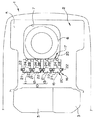
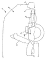
以下、図面を参照して本発明の実施の形態を説明する。図1乃至図4は本発明の第1の実施の一形態に係わり、図1はラゲージルームの要部を示す平面図、図2はスペアタイヤ衝突時のバッテリの挙動を示す説明図、図3はバッテリ及びバッテリホルダを示す分解斜視図、図4はバッテリホルダの変形例を示す説明図である。
【0023】
図1において符号1は車体を示す。本実施の形態において、車体1には、定格電圧が例えば42Vに設定されたモータジェネレータや電動オイルポンプ等の各補機類(図示せず)と、定格電圧が例えば14Vに設定されたランプバルブやオーディオ機器等の各補機類(図示せず)とが搭載されている。そして、高出力なモータジェネレータ等の補機類を搭載することにより、車体1にはアイドルストップ機能等を高いクオリティで実現可能な簡易ハイブリッドシステムが構築されている。
【0024】
また、定格電圧の異なる各補機類にそれぞれ対応して給電を行うため、車体1には、リヤシート3後部に設定されたラゲージルーム2内に、36Vバッテリ10と、12Vバッテリ15とが搭載されている。
【0025】
ラゲージルーム2を構成するフロアパネル5は略平坦なパネル部材で構成され、フロアパネル5の下部には、スペアタイヤ6を収容するためのスペアタイヤトレイ7が設けられている。本実施の形態において、スペアタイヤトレイ7は、フロアパネル5に一体形成されるもので、ラゲージルーム2内の右側かつ後方に偏倚した位置でフロアパネル5に凹設されている。また、図2に示すように、スペアタイヤトレイ7の前側壁面には、所定角度の傾斜部8が設けられている。傾斜部8は後突時にスペアタイヤ6を車体前方に跳ね上げるようガイドするためのもので(図2中2点鎖線参照)、スペアタイヤ6が車体前方に跳ね上げられて放出されることにより、スペアタイヤトレイ7は後突時のクラッシュストロークとして機能するようになっている。
【0026】
36Vバッテリ10は、扁平な略直方体形状をなす3個のバッテリ(12Vバッテリ)11〜13を有して構成されている。各バッテリ11〜13の端子面は最小面積を有する一面に設定され、この端子面から露呈された各端子(図示せず)が直列接続されることにより36Vの出力電圧を実現する。また、12Vバッテリ15は、バッテリ11〜13と略同型の扁平な略直方体形状をなす単一のバッテリで構成され、最小面積を有する一面が端子面として設定されている。ここで、各バッテリ11〜13及び12Vバッテリ15は、例えば、周知のシール鉛蓄電池で構成されている。
【0027】
36Vバッテリ10を構成するバッテリ11〜13、及び、12Vバッテリ15は、スペアタイヤトレイ7の前方で車幅方向に沿ってフロアパネル5上に配列され、これらの前後に連設された保持手段としてのバッテリホルダ16,17を介してフロアパネル5上に保持されている。
【0028】
ここで、各バッテリ11〜13,15は、各端子面が車体前方にそれぞれ臨まされた状態であって、且つ、後部の一部がスペアタイヤトレイ7の前部に露呈された状態で、フロアパネル5に倒伏して配置されている。そして、このように各バッテリ11〜13,15を倒伏してフロアパネル5上に配列することにより、バッテリ11〜13,15をラゲージルーム2内に配設した際にも良好なスペースユーティリティが確保される。この場合、各バッテリ11〜13,15をシール鉛蓄電池で構成することにより、バッテリ11〜13,15の各端子を上方に露呈させる必要がなくなり、バッテリ11〜13,15の配設方向に自由度を持たせることができる。
【0029】
図1〜図3に示すように、バッテリホルダ16は、例えば板金部材で構成されるもので、細長のバンド部20を有して構成されている。バンド部20には、各バッテリ11〜13,15の前部側面から前面にかけて各バッテリ11〜13,15の下部にそれぞれ当接するバッテリ当接部21が折曲形成されており、さらに、バンド部20の両端及び中途にはフロアパネル5に当接するフロア当接部22が形成されている。そして、バッテリホルダ16は、バンド部20に形成されたフロア当接部22を介してボルト締結されることでフロアパネル5上に強固に固定され、各バッテリ11〜13,15の車体前方への移動を規制するようになっている。また、バンド部20には、各バッテリ11〜13,15の左右側面に沿って上方にそれぞれ延出する腕部23が設けられている。これら各腕部23の先端部は対応する各バッテリ11〜13,15の上部でそれぞれ内側に指向して折曲されており、これにより、各腕部23の先端部は、各バッテリ11〜13,15の前部上面をそれぞれ係止する係止部24として構成されている。そして、各バッテリ11〜13,15は、各係止部24に係止されることによって、前部の上下方向への移動が規制されている。また、係止部24は、所定の衝撃によって変形可能に構成されており、これにより、係止部24は、スペアタイヤ6の衝突時に変形してバッテリ11〜13,15の前部上面に対する係止を解放するようになっている。
【0030】
バッテリホルダ17は、例えば板金部材で構成されるもので、バッテリ11〜13,15の後面に当接する細長のバンド部25を有して構成されている。バンド部25には下方に屈曲して延出する脚部26が設けられ、バッテリホルダ17は、脚部26を介してボルト締結されることで傾斜部8上に強固に固定されている。また、バンド部25には、各バッテリ11〜13,15の後面に沿って上方にそれぞれ延出する腕部27が設けられている。これら各腕部27の先端部は対応する各バッテリ11〜13,15の上部でそれぞれ前方に指向して折曲されており、これにより、各腕部27の先端部は、各バッテリ11〜13,15の後部上面をそれぞれ係止する係止部28として構成されている。そして、各バッテリ11〜13,15は、各係止部28に係止されることによって、後部の上下方向への移動が規制されている。また、係止部28は、所定の衝撃によって変形可能に構成されており、これにより、係止部24は、スペアタイヤ6の衝突時に変形してバッテリ11〜13,15の後部上面に対する係止を解放するようになっている。
【0031】
そして、これらの構成において、後突時に傾斜部8にガイドされて車体前方に跳ね上げられたスペアタイヤ6がバッテリ11〜13,15の後部に下方から衝突した際には、各係止部24,28がバッテリ11〜13,15上面の係止を解放する(図2中2点鎖線参照)とともにバッテリ当接部21がバッテリ11〜13,15の車体前方への移動を規制することにより、各係止部24,28及びバッテリ当接部21は、バッテリ11〜13,15が前部下方を支点として回転移動するようガイドするガイド手段としての機能を実現する。
【0032】
このような実施の形態によれば、後突時に傾斜部8にガイドされて車体前方に跳ね上げられたスペアタイヤ6がバッテリ11〜13,15の後部に下方から衝突した際には、バッテリホルダ16,17はバッテリ11〜13,15が前部下方を支点として回転移動するようガイドするので、スペアタイヤ6がバッテリ11〜13,15に衝突した際にも、当該衝突による衝撃がバッテリ11〜13,15に影響することを防止でき、各バッテリ11〜13,15の破損を的確に防止することができると共に、バッテリによりスペアタイヤの移動が阻害されることを防ぐことができる。
【0033】
ここで、本実施の形態においては、図4に示すように、スペアタイヤ6に対向する凸部29を脚部26に形成してもよい。このような凸部29を脚部26に設けることにより、スペアタイヤ6の衝突時に、バッテリホルダ17の変形を促進することができ、係止部28によるバッテリ11〜13,15上面の係止をスムーズに解放することができる。
【0034】
なお、上述の実施の形態においては、係止部24,28によってバッテリ11〜13,15の上面を下方から係止する一例について説明したが、本発明はこれに限定されるものではなく、例えば、係止部24或いは係止部28の何れか一方によってバッテリ11〜13,15の上面を係止するものであってもよい。
【0035】
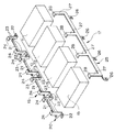
次に、図5乃至図7は本発明の第2の実施の形態に係わり、図5はラゲージルームの要部を示す側面図、図6はラゲージルームの要部を示す平面図、図7はバッテリ及びステーを示す分解斜視図である。なお、本実施の形態においては、バッテリホルダ16,17に代えて、ステー35を介して各バッテリ11〜13,15の底面後部をフロアパネル5上に保持した点が上述の第1の実施の形態と主として異なる。その他、同様の構成については同符号を付して説明を省略する。
【0036】
図示のように、各バッテリ11〜13,15は、その後部底面が、車幅方向に延在し、スペアタイヤトレイの上方に掛け渡された保持手段としてのステー35を介して一体的に連結されている。
【0037】
具体的に説明すると、ステー35は、例えば前後にフランジ36を有する断面略”ハット”形状の板金部材で構成され、左右両端がフランジ36を介してフロアパネル5上にボルト締結されている。また、ステー35の上面には、各バッテリ11〜13,15の後部底面が連結されているとともに、バッテリ11〜13,15の連結位置に略対応する位置に、複数の切り欠き37が設けられている。そして、このようにステー35の上面に切り欠き37が設けられることによって、ステー35は、下方への撓み強度が維持されたまま、上方への強度のみが所定に脆弱な構成となっている。すなわち、上面に切り欠き37を設けることによってステー35には車体上方への変形を許容する脆弱部38が設定され、この脆弱部38は、バッテリ11〜13,15の後部に下方からスペアタイヤ6が衝突した際に変形されることによって、バッテリ11〜13,15が前部下方を支点として回転移動するようガイドするガイド手段としての機能を実現する。
【0038】
ここで、本実施の形態において、各バッテリ11〜13,15は、車外において予めステー35に組み付けられた状態で、ラゲージルーム2内に搬入されて固設される。
【0039】
このような実施の形態によれば、後突時に傾斜部8にガイドされて車体前方に跳ね上げられたスペアタイヤ6がバッテリ11〜13,15の後部に下方から衝突した際には、脆弱部38での変形によって、ステー35は各バッテリ11〜13,15が前部下方を支点として回転移動するようガイドするので、スペアタイヤ6がバッテリ11〜13,15に衝突した際にも、当該衝突による衝撃がバッテリ11〜13,15に影響することを防止でき、各バッテリ11〜13,15の破損を的確に防止することができると共に、バッテリによりスペアタイヤの移動が阻害されることを防ぐことができる。
【0040】
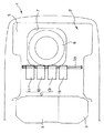
次に、図8乃至図10は本発明の第3の実施の形態に係わり、図8はラゲージルームの要部を示す側面図、図9はラゲージルームの要部を示す平面図、図10はバッテリ及びステーを示す分解斜視図である。なお、本実施の形態においては、バッテリホルダ16,17に代えて、ステー40を介して各バッテリ11〜13,15の底面前部をフロアパネル5上に保持した点が上述の第1の実施の形態と主として異なる。その他、同様の構成については同符号を付して説明を省略する。
【0041】
図示のように、各バッテリ11〜13,15は、その前部底面が、フロアパネル5上に架設された保持手段としてのステー40を介して一体的に連結されている。
【0042】
具体的に説明すると、ステー40は、例えば前後にフランジ41を有する断面略”ハット”形状の板金部材で構成され、左右両端がフランジ41を介してフロアパネル5上にボルト締結されている。また、ステー40の後部側フランジ41上には、各バッテリ11〜13,15の前部底面が連結されている。また、ステー40の後面には、車体前方に傾斜された傾斜面42と、この傾斜面42の下部に連設する段部43とが一体形成され、この段部43にはバッテリ11〜13,15の前面下部が当接されている。そして、段部43は、バッテリ11〜13,15の後部に下方からスペアタイヤ6が衝突された際に、バッテリ11〜13,15の車体前方への移動を規制することにより、バッテリ11〜13,15が前部下方を支点として回転移動するようガイドするガイド手段としての機能を実現する。その際、段部43の上部に傾斜面42を形成することにより、各バッテリ11〜13,15は良好な回転移動が許容される。
【0043】
このような実施の形態によれば、後突時に傾斜部8にガイドされて車体前方に跳ね上げられたスペアタイヤ6がバッテリ11〜13,15の後部に下方から衝突した際には、ステー40は、段部43によってバッテリ11〜13,15が前部下方を支点として回転移動するようガイドするので、スペアタイヤ6がバッテリ11〜13,15に衝突した際にも、当該衝突による衝撃がバッテリ11〜13,15に影響することを防止でき、各バッテリ11〜13,15の破損を的確に防止することができると共に、バッテリによりスペアタイヤの移動が阻害されることを防ぐことができる。
【0044】
次に、図11乃至図16は本発明の第4の実施の形態に係わり、図11はラゲージルームの要部を示す平面図、図12はバッテリ及びバッテリトレイを示す分解斜視図、図13はバッテリトレイの連結状態を示す説明図、図14はバッテリトレイの他の連結状態を示す説明図、図15はバッテリ及びバッテリトレイを示す平面図、図16はバッテリトレイの変形例を示す分解斜視図である。なお、本実施の形態においては、バッテリホルダ16,17に代えて、バッテリトレイ50を介して各バッテリ11〜13,15をフロアパネル5上に保持した点が上述の第1の実施の形態と主として異なる。その他、同様の構成については同符号を付して説明を省略する。
【0045】
図11,12に示すように、各バッテリ11〜13,15は、保持手段としてのバッテリトレイ50を介してフロアパネル5上に保持されている。バッテリトレイ50は、例えば板金部材で構成されるもので、各バッテリ11〜13,15は、バッテリトレイ50上に倒伏して配列された状態で、図示しないバンド等を介して固定されている。
【0046】
また、バッテリトレイ50の左右両端に設けられたフランジ51からは先端が下方に指向する一対の爪部52がそれぞれ延設されており、これら爪部52が連結手段としてのブラケット55に係合されることで、バッテリトレイ50はフロアパネル5上に連結されている。
【0047】
具体的に説明すると、ブラケット55は、例えば板金部材で構成されるもので、バッテリトレイ50が係合される係合面56を有して構成されている。この係合面56からはフロアパネル5に連結する脚部57が延設されており、ブラケット55は、脚部57を介したボルト締結によってフロアパネル5上に強固に固定されている。
【0048】
また、係合面56には爪部52に対応して上方に開口するスリット58が設けられており、このスリット58に爪部52が上方から挿入されることによって、バッテリトレイ50はフロアパネル5上に固設されている。
【0049】
ここで、本実施の形態において、バッテリトレイ50は車外において予めブラケット55に連結されるようになっており、各バッテリ11〜13,15は、このバッテリトレイ50に車外において予め組み付けられた状態で、ラゲージルーム2内に搬入されて固定される。その際の搬送を容易なものとするため、ブラケット55の係合面56には長孔59が設けられ、この長孔59は搬送時の把持部として機能するようになっている。また、図13に示すように、係合面56には、スリット58に沿って下方に延出する係止部60が設けられており、この係止部60によって、スリット58に挿入された爪部52の揺動が規制されるようになっている。なお、図14に示すように、係止部60は、係合面56を折曲することによって構成されるものであってもよい。さらに、図12に示すように、車両横転時においてバッテリトレイ50とブラケット55との連結が解放されるのを防止するため、バッテリトレイ50とブラケット55とをスチール製のワイヤー62等で連結している。
【0050】
このような実施の形態によれば、後突時に傾斜部8にガイドされて車体前方に跳ね上げられたスペアタイヤ6がバッテリ11〜13,15(バッテリトレイ50)の後部に下方から衝突した際には、ブラケット55は爪部52によるバッテリトレイ50との連結を解放するので、スペアタイヤ6がバッテリ11〜13,15に衝突した際にも、当該衝突による衝撃がバッテリ11〜13,15に影響することを防止でき、各バッテリ11〜13,15の破損を的確に防止することができると共に、バッテリによりスペアタイヤの移動が阻害されることを防ぐことができる。
【0051】
また、各バッテリ11〜13,15を予めバッテリトレイ50に組み付けるとともに、バッテリトレイ50を予めブラケット55に連結した状態でラゲージルーム2内に搬入することにより、狭隘なラゲージルーム2内での各バッテリ11〜13,15のバッテリトレイ50への組付作業等を防止しして組み付け性を向上することができる。この場合において、ブラケット55を各バッテリ11〜13,15の搬送時のキャリヤとして利用することができる。
【0052】
ここで、本実施の形態においては、図15,16に示すように、スペアタイヤ6に衝突される可能性が高いバッテリ(例えばバッテリ12,13)のみを保持手段としてのバッテリトレイ50に載置保持し、他のバッテリ(例えばバッテリ11,15)を連結手段としてのバッテリトレイ61に載置保持する構成としてもよい。このように構成することによって、バッテリトレイを小型なものとすることができ、バッテリトレイの製造を容易なものとすることができる。
【0053】
なお、上述の各実施の形態においては、3個のバッテリ11〜13で分割形成された36Vバッテリ10と12Vバッテリ15とをラゲージルーム2内のフロアパネル5上に取り付ける際の取付装置について説明したが、本発明はこれに限定されるものではなく、バッテリの電圧及び個数等は適宜変更可能であることは勿論である。
【0054】
【発明の効果】
以上説明したように本発明によれば、後突時に跳ね上げられたスペアタイヤの衝突によるバッテリの破損を的確に防止することができると共に、バッテリによりスペアタイヤの移動が阻害されるのを防ぐことができる。
【図面の簡単な説明】
【図1】本発明の第1の実施の一形態に係わり、ラゲージルームの要部を示す平面図
【図2】同上、スペアタイヤ衝突時のバッテリの挙動を示す説明図
【図3】同上、バッテリ及びバッテリホルダを示す分解斜視図
【図4】同上、バッテリホルダの変形例を示す説明図
【図5】本発明の第2の実施の形態に係わり、ラゲージルームの要部を示す側面図
【図6】同上、ラゲージルームの要部を示す平面図
【図7】同上、バッテリ及びステーを示す分解斜視図
【図8】本発明の第3の実施の形態に係わり、ラゲージルームの要部を示す側面図
【図9】同上、ラゲージルームの要部を示す平面図
【図10】同上、バッテリ及びステーを示す分解斜視図
【図11】本発明の第4の実施の形態に係わり、ラゲージルームの要部を示す平面図
【図12】同上、バッテリ及びバッテリトレイを示す分解斜視図
【図13】同上、バッテリトレイの連結状態を示す説明図
【図14】同上、バッテリトレイの他の連結状態を示す説明図
【図15】同上、バッテリ及びバッテリトレイを示す平面図
【図16】同上、バッテリトレイの変形例を示す分解斜視図
【符号の説明】
1 … 車体
2 … ラゲージルーム
5 … フロアパネル
6 … スペアタイヤ
7 … スペアタイヤトレイ
11〜13,15 … バッテリ
16,17 … バッテリホルダ(保持手段)
21 … バッテリ当接部(当接部;保持手段、ガイド手段)
24,28 … 係止部(保持手段、ガイド手段)
35 … ステー(保持手段)
38 … 脆弱部(ガイド手段)
40 … ステー(保持手段)
43 … 段部(ガイド手段)
50 … バッテリトレイ(保持手段)
52 … 爪部
55 … ブラケット(連結手段)
58 … スリット
60 … 係止部[0001]
BACKGROUND OF THE INVENTION
The present invention is a mounting method in which a battery is disposed in front of a spare tire housed in a luggage room. apparatus About.
[0002]
[Prior art]
In recent years, in vehicles, a simple hybrid system using a motor generator, an electric four-wheel drive system, an electromagnetically driven valve, an electric power steering, an electric car air conditioner, an electric brake, an electric chassis control, a quick defrosting device for a windshield, a seat heater, etc. In order to realize each of the above equipments with high quality, it has been studied to increase the rated voltage of in-vehicle accessories from 14V to 42V, and accordingly, the in-vehicle battery voltage is increased from 12V to 36V. It is being considered to increase the pressure.
[0003]
In such a transition period to boosting of auxiliary equipment, in order to suppress the cost increase accompanying the change of auxiliary equipment, boosting of auxiliary equipment can enjoy more merit by the boosting It is desirable to introduce them in stages. In this case, as one of the greatest merits expected by boosting the auxiliary machinery, it is conceivable to improve fuel efficiency by constructing a simple hybrid system using a high-output motor generator. Therefore, in recent years, both a 36V battery and a 12V battery are mounted. For example, a motor generator, an electromagnetic clutch, and an electric oil pump for an automatic transmission are driven by a 36V battery, and other auxiliary machines are driven by a 12V battery. Technology to do this has been proposed and put into practical use.
[0004]
However, in the vehicle including the 36V battery and the 12V battery as described above, it is difficult to mount both batteries in a narrow engine room at the same time. Further, when a motor generator is employed in the vehicle, it is necessary to newly install an inverter device. Furthermore, in order to reduce the power generation voltage generated by the motor generator to supply power to a 12V battery or the like, it is necessary to newly install auxiliary equipment such as a DC-DC converter.
[0005]
In response to these problems, for example, in Non-Patent Document 1, 36V battery and 12V battery are arranged on the floor panel in the luggage room, and each battery is arranged in the luggage room, so that it is secured in the engine room. A technique is disclosed in which an inverter device that is integrally provided with a DC-DC converter is disposed in a space.
[0006]
Further, as a mounting structure of 36V battery and 12V battery, the above-mentioned Non-Patent Document 1 discloses that a 36V battery and 12V battery are mounted between a battery carrier and a hole down pipe that are installed in front of the spare tire in the luggage width direction. A technique for fixing a battery via a clamp mechanism is disclosed.
[0007]
[Non-Patent Document 1]
Edited by Toyota Motor Co., Ltd. “Crown, Crown Majesta, Crown Estate New Model Manual” issued on August 20, 2001, P0-2, P1-2-1-7, P1-12-1-21, P4-4
[0008]
[Problems to be solved by the invention]
By the way, in a vehicle, it is general that a spare tire tray that accommodates a spare tire in a luggage room functions as a crash stroke at the time of a rear collision. For this reason, the front surface of the spare tire tray is provided with an inclined portion for guiding a high-rigidity spare tire to jump up to the front of the vehicle body at the time of a rear collision.
[0009]
Therefore, when the battery is disposed in front of the spare tire as in the technique disclosed in Non-Patent Document 1 described above, the battery is offset from the trajectory of the spare tire predicted at the time of the rear collision from the viewpoint of battery protection. It is desirable to be disposed at a position, and it is more desirable to be disposed at a position sufficiently separated from the spare tire.
[0010]
However, depending on the shape of the vehicle body, the layout of each member mounted on the vehicle body, etc., there are cases where the battery has to be disposed on the trajectory of the spare tire predicted at the time of the rear collision. In particular, when a part of the rear part of the battery is exposed to the spare tire tray, there is a possibility that the spare tire bounced up at the time of the rear collision may collide with the rear part of the battery from below and damage the battery.
[0011]
The present invention has been made in view of the above circumstances, and prevents a battery from being damaged due to a collision of a spare tire that is flipped up at the time of a rear collision, and can prevent a movement of the spare tire from being inhibited by the battery. Mounting apparatus The purpose is to provide.
[0012]
[Means for Solving the Problems]
In order to solve the above-mentioned problem, the invention according to claim 1 has a spare tire tray formed with an inclined portion for jumping up the spare tire and guiding it forward of the vehicle body at the time of a rear collision at the lower part of the floor panel in the luggage room, Installation of a battery having a battery held on the floor panel by a holding means in front of the spare tire tray, at least a rear portion of the battery facing the spare tire tray apparatus The holding means is provided with guide means for guiding the battery to rotate about the front lower portion when the spare tire collides with the rear portion of the battery from below.
[0013]
A battery mounting according to the invention of
[0014]
A battery mounting according to the invention of
[0015]
Further, the battery mounting according to the invention of claim 4 apparatus In the invention according to
[0016]
Further, the battery mounting according to the invention of claim 5 apparatus In the first aspect of the present invention, the holding means is a stay connected to the front bottom of the battery, and the guide means is provided integrally with the stay and contacts the lower front portion of the battery. It is the step part which touches, It is characterized by the above-mentioned.
[0017]
A battery mounting according to the invention of
[0018]
According to a seventh aspect of the present invention, a spare tire tray having an inclined portion formed to guide the front of the vehicle body by jumping up the spare tire at the time of a rear collision is provided at a lower portion of the floor panel in the luggage room. Mounting of a battery having a battery held on the floor panel by a holding means in front and at least a rear portion of the battery facing the spare tire tray apparatus And having connecting means for connecting the holding means on the floor panel, the connecting means releasing the connection of the holding means when the spare tire collides with the rear part of the battery from below. It is characterized by.
[0019]
A battery mounting according to the invention of claim 8 apparatus In the invention according to
[0020]
A battery mounting according to the invention of claim 9 apparatus The invention according to claim 8 is characterized in that the connecting means has a locking portion for restricting the swing of the claw portion inserted in the slit.
[0021]
A battery mounting according to the invention of
[0022]
DETAILED DESCRIPTION OF THE INVENTION
Embodiments of the present invention will be described below with reference to the drawings. 1 to 4 relate to a first embodiment of the present invention, FIG. 1 is a plan view showing the main part of the luggage room, FIG. 2 is an explanatory view showing the behavior of the battery at the time of spare tire collision, FIG. Is an exploded perspective view showing a battery and a battery holder, and FIG. 4 is an explanatory view showing a modification of the battery holder.
[0023]
In FIG. 1, reference numeral 1 denotes a vehicle body. In the present embodiment, the vehicle body 1 includes an auxiliary machine (not shown) such as a motor generator and an electric oil pump whose rated voltage is set to 42 V, for example, and a lamp valve whose rated voltage is set to 14 V, for example. And auxiliary devices (not shown) such as audio equipment. A simple hybrid system capable of realizing an idle stop function and the like with high quality is built in the vehicle body 1 by mounting auxiliary equipment such as a high-power motor generator.
[0024]
Further, in order to supply power corresponding to each auxiliary machine having different rated voltages, the vehicle body 1 is mounted with a
[0025]
The floor panel 5 constituting the
[0026]
The
[0027]
The
[0028]
Here, each of the
[0029]
As shown in FIGS. 1 to 3, the
[0030]
The
[0031]
In these configurations, when the
[0032]
According to such an embodiment, when the
[0033]
Here, in the present embodiment, as shown in FIG. 4, a convex portion 29 facing the
[0034]
In the above-described embodiment, an example in which the upper surfaces of the
[0035]
Next, FIGS. 5 to 7 relate to a second embodiment of the present invention, FIG. 5 is a side view showing the main part of the luggage room, FIG. 6 is a plan view showing the main part of the luggage room, and FIG. It is a disassembled perspective view which shows a battery and a stay. In the present embodiment, instead of the
[0036]
As shown in the figure, the rear surfaces of the
[0037]
More specifically, the
[0038]
Here, in the present embodiment, each of the
[0039]
According to such an embodiment, when the
[0040]
Next, FIGS. 8 to 10 relate to a third embodiment of the present invention, FIG. 8 is a side view showing the main part of the luggage room, FIG. 9 is a plan view showing the main part of the luggage room, and FIG. It is a disassembled perspective view which shows a battery and a stay. In the present embodiment, instead of the
[0041]
As shown in the drawing, the front bottom surfaces of the
[0042]
More specifically, the
[0043]
According to such an embodiment, when the
[0044]
Next, FIGS. 11 to 16 relate to a fourth embodiment of the present invention, FIG. 11 is a plan view showing the main part of the luggage room, FIG. 12 is an exploded perspective view showing a battery and a battery tray, and FIG. FIG. 14 is an explanatory view showing another connection state of the battery tray, FIG. 15 is a plan view showing the battery and the battery tray, and FIG. 16 is an exploded perspective view showing a modification of the battery tray. It is. In the present embodiment, instead of the
[0045]
As shown in FIGS. 11 and 12, the
[0046]
In addition, a pair of
[0047]
More specifically, the
[0048]
In addition, the engaging
[0049]
Here, in the present embodiment, the
[0050]
According to such an embodiment, when the
[0051]
In addition, each
[0052]
Here, in the present embodiment, as shown in FIGS. 15 and 16, only the batteries (for example, the
[0053]
In each of the above-described embodiments, attachment when
[0054]
【The invention's effect】
As described above, according to the present invention, it is possible to accurately prevent the damage of the battery due to the collision of the spare tire that is flipped up at the time of the rear collision, and to prevent the movement of the spare tire by the battery. Can do.
[Brief description of the drawings]
FIG. 1 is a plan view showing a main part of a luggage room according to an embodiment of the present invention.
FIG. 2 is an explanatory diagram showing the behavior of a battery when a spare tire collides with the above.
FIG. 3 is an exploded perspective view showing the battery and the battery holder.
FIG. 4 is an explanatory view showing a modification of the battery holder as above.
FIG. 5 is a side view showing a main part of a luggage room according to a second embodiment of the present invention.
FIG. 6 is a plan view showing the main part of the luggage room.
FIG. 7 is an exploded perspective view showing the battery and the stay.
FIG. 8 is a side view showing a main part of a luggage room according to a third embodiment of the present invention.
FIG. 9 is a plan view showing the main part of the luggage room
FIG. 10 is an exploded perspective view showing the battery and the stay.
FIG. 11 is a plan view showing a main part of a luggage room according to a fourth embodiment of the present invention.
FIG. 12 is an exploded perspective view showing the battery and the battery tray.
FIG. 13 is an explanatory view showing a connected state of the battery tray as in the above.
FIG. 14 is an explanatory view showing another connection state of the battery tray as in the above.
FIG. 15 is a plan view showing the battery and the battery tray as in the above.
FIG. 16 is an exploded perspective view showing a modification of the battery tray of the above.
[Explanation of symbols]
1 ... Body
2 ... Luggage room
5… Floor panel
6 ... spare tire
7 ... Spare tire tray
11 to 13, 15 ... battery
16, 17 ... Battery holder (holding means)
21 ... Battery contact portion (contact portion; holding means, guide means)
24, 28 ... Locking portion (holding means, guide means)
35 ... Stay (holding means)
38 ... Vulnerable part (guide means)
40 ... Stay (holding means)
43 ... Step (guide means)
50 ... Battery tray (holding means)
52 ... Claw
55 ... Bracket (connection means)
58… slit
60 ... Locking part
Claims (10)
上記保持手段に、上記スペアタイヤが上記バッテリの後部に下方から衝突した際に上記バッテリが前部下方を支点として回転移動するようガイドするガイド手段を設けたことを特徴とするバッテリの取付装置。There is a spare tire tray formed in the lower part of the floor panel in the luggage room that has an inclined portion that guides the spare tire to the front of the vehicle body by jumping up at the time of a rear collision, and is placed on the floor panel by a holding means in front of the spare tire tray. A battery mounting device having a battery to be held, at least a rear portion of the battery facing the spare tire tray,
A battery mounting device , characterized in that the holding means is provided with guide means for guiding the battery to rotate around the front lower part when the spare tire collides with the rear part of the battery from below.
上記スペアタイヤが上記バッテリの後部に下方から衝突した際に、上記係止部が上記バッテリ上面の係止を解放するとともに上記当接部が上記バッテリの車体前方への移動を規制することで、上記係止部及び上記当接部は上記ガイド手段として機能することを特徴とする請求項1記載のバッテリの取付装置。The holding means includes a locking portion that locks the upper surface of the battery from below, and a contact portion that contacts the front surface of the battery,
When the spare tire collides with the rear portion of the battery from below, the locking portion releases the locking of the upper surface of the battery and the contact portion restricts the movement of the battery forward of the vehicle body. 2. The battery mounting device according to claim 1, wherein the locking portion and the contact portion function as the guide means.
上記ガイド手段は、上記ステーの上方への変形を許容する脆弱部であることを特徴とする請求項1記載のバッテリの取付装置。The holding means is a stay that extends in the vehicle width direction, spans above the spare tire tray, and is connected to the bottom rear portion of the battery,
2. The battery mounting device according to claim 1, wherein the guide means is a fragile portion that allows the stay to be deformed upward.
上記ガイド手段は、上記ステーに一体的に設けられて上記バッテリの前面下部に当接する段部であることを特徴とする請求項1記載のバッテリの取付装置。The holding means is a stay connected to the bottom front portion of the battery,
2. The battery mounting device according to claim 1, wherein the guide means is a step provided integrally with the stay and abutted against a lower front surface of the battery.
上記保持手段を上記フロアパネル上に連結する連結手段を有し、
上記連結手段は、上記スペアタイヤが上記バッテリの後部に下方から衝突した際に上記保持手段の連結を解放することを特徴とするバッテリの取付装置。There is a spare tire tray formed in the lower part of the floor panel in the luggage room that has an inclined portion that guides the spare tire to the front of the vehicle body by jumping up at the time of a rear collision, and is placed on the floor panel by a holding means in front of the spare tire tray. A battery mounting device having a battery to be held, at least a rear portion of the battery facing the spare tire tray,
Having connecting means for connecting the holding means on the floor panel;
The battery attachment device, wherein the connection means releases the connection of the holding means when the spare tire collides with the rear portion of the battery from below.
上記保持手段に設けられた爪部が上記スリットに上方から挿入されることによって上記保持手段を上記フロアパネル上に連結することを特徴とする請求項7記載のバッテリの取付装置。The connecting means has a slit opening upward,
8. The battery mounting apparatus according to claim 7, wherein a claw portion provided on the holding means is inserted into the slit from above, whereby the holding means is connected to the floor panel.
Priority Applications (1)
| Application Number | Priority Date | Filing Date | Title |
|---|---|---|---|
| JP2003057650A JP4425552B2 (en) | 2003-03-04 | 2003-03-04 | Battery mounting device |
Applications Claiming Priority (1)
| Application Number | Priority Date | Filing Date | Title |
|---|---|---|---|
| JP2003057650A JP4425552B2 (en) | 2003-03-04 | 2003-03-04 | Battery mounting device |
Publications (2)
| Publication Number | Publication Date |
|---|---|
| JP2004265839A JP2004265839A (en) | 2004-09-24 |
| JP4425552B2 true JP4425552B2 (en) | 2010-03-03 |
Family
ID=33121003
Family Applications (1)
| Application Number | Title | Priority Date | Filing Date |
|---|---|---|---|
| JP2003057650A Expired - Fee Related JP4425552B2 (en) | 2003-03-04 | 2003-03-04 | Battery mounting device |
Country Status (1)
| Country | Link |
|---|---|
| JP (1) | JP4425552B2 (en) |
Families Citing this family (2)
| Publication number | Priority date | Publication date | Assignee | Title |
|---|---|---|---|---|
| JP6171946B2 (en) * | 2014-01-22 | 2017-08-02 | トヨタ自動車株式会社 | Car with battery pack |
| JP6717173B2 (en) * | 2016-11-28 | 2020-07-01 | トヨタ自動車株式会社 | Vehicle-mounted structure of electrical equipment |
Family Cites Families (6)
| Publication number | Priority date | Publication date | Assignee | Title |
|---|---|---|---|---|
| JPH0810029Y2 (en) * | 1990-01-16 | 1996-03-27 | スズキ株式会社 | Car battery storage structure |
| JPH05201355A (en) * | 1992-01-24 | 1993-08-10 | Honda Motor Co Ltd | Electric vehicle body structure |
| JPH05201354A (en) * | 1992-01-24 | 1993-08-10 | Honda Motor Co Ltd | Electric vehicle body structure |
| JPH05201356A (en) * | 1992-01-24 | 1993-08-10 | Honda Motor Co Ltd | Car body structure of electric automobile |
| JP3817953B2 (en) * | 1999-02-22 | 2006-09-06 | マツダ株式会社 | Vehicle battery mounting structure |
| JP3879339B2 (en) * | 1999-11-17 | 2007-02-14 | マツダ株式会社 | Lower body structure of the vehicle |
-
2003
- 2003-03-04 JP JP2003057650A patent/JP4425552B2/en not_active Expired - Fee Related
Also Published As
| Publication number | Publication date |
|---|---|
| JP2004265839A (en) | 2004-09-24 |
Similar Documents
| Publication | Publication Date | Title |
|---|---|---|
| JP4346928B2 (en) | Battery mounting structure | |
| JP6363656B2 (en) | Automotive battery | |
| CN102548788B (en) | Vehicle charging port arrangement | |
| JP6118381B2 (en) | Automotive battery | |
| US9365165B2 (en) | Onboard equipment fixing structure | |
| JP6626903B2 (en) | Mounting structure of high voltage control equipment unit | |
| JP4274819B2 (en) | Battery mounting structure | |
| US11318992B2 (en) | Vehicle lower structure | |
| JP5532128B2 (en) | Mounting structure for electrical equipment at the rear of the vehicle body | |
| US20090294626A1 (en) | Mounting structure | |
| WO2006054134A2 (en) | Inverter buffer structure for a hybrid vehicle | |
| JP2010285058A (en) | Rear structure of the car body | |
| US20210371011A1 (en) | Electric powered vehicle | |
| JP2016078713A (en) | Vehicle high voltage electric device mounting structure | |
| JP5928289B2 (en) | High voltage harness protection structure for vehicles | |
| JP2005093299A (en) | Battery mounting structure | |
| US12545129B2 (en) | Fuel cell vehicle | |
| JP2004265840A (en) | Battery terminal connection structure | |
| JP4505716B2 (en) | Electric equipment fixing structure of vehicle | |
| JP2022180716A (en) | Lower part structure for vehicle | |
| JP4425552B2 (en) | Battery mounting device | |
| US12509154B2 (en) | Inverter mounting structure for vehicle | |
| JP2004265841A (en) | Battery terminal connection structure | |
| JP2006199051A (en) | Wiring structure of wire harness | |
| JP7210117B2 (en) | Blower support structure |
Legal Events
| Date | Code | Title | Description |
|---|---|---|---|
| A621 | Written request for application examination |
Free format text: JAPANESE INTERMEDIATE CODE: A621 Effective date: 20060303 |
|
| A977 | Report on retrieval |
Free format text: JAPANESE INTERMEDIATE CODE: A971007 Effective date: 20090817 |
|
| A131 | Notification of reasons for refusal |
Free format text: JAPANESE INTERMEDIATE CODE: A131 Effective date: 20090908 |
|
| A521 | Request for written amendment filed |
Free format text: JAPANESE INTERMEDIATE CODE: A523 Effective date: 20091026 |
|
| TRDD | Decision of grant or rejection written | ||
| A01 | Written decision to grant a patent or to grant a registration (utility model) |
Free format text: JAPANESE INTERMEDIATE CODE: A01 Effective date: 20091117 |
|
| A01 | Written decision to grant a patent or to grant a registration (utility model) |
Free format text: JAPANESE INTERMEDIATE CODE: A01 |
|
| A61 | First payment of annual fees (during grant procedure) |
Free format text: JAPANESE INTERMEDIATE CODE: A61 Effective date: 20091209 |
|
| R150 | Certificate of patent or registration of utility model |
Ref document number: 4425552 Country of ref document: JP Free format text: JAPANESE INTERMEDIATE CODE: R150 Free format text: JAPANESE INTERMEDIATE CODE: R150 |
|
| FPAY | Renewal fee payment (event date is renewal date of database) |
Free format text: PAYMENT UNTIL: 20121218 Year of fee payment: 3 |
|
| FPAY | Renewal fee payment (event date is renewal date of database) |
Free format text: PAYMENT UNTIL: 20121218 Year of fee payment: 3 |
|
| FPAY | Renewal fee payment (event date is renewal date of database) |
Free format text: PAYMENT UNTIL: 20131218 Year of fee payment: 4 |
|
| R250 | Receipt of annual fees |
Free format text: JAPANESE INTERMEDIATE CODE: R250 |
|
| R250 | Receipt of annual fees |
Free format text: JAPANESE INTERMEDIATE CODE: R250 |
|
| S531 | Written request for registration of change of domicile |
Free format text: JAPANESE INTERMEDIATE CODE: R313531 |
|
| R350 | Written notification of registration of transfer |
Free format text: JAPANESE INTERMEDIATE CODE: R350 |
|
| R250 | Receipt of annual fees |
Free format text: JAPANESE INTERMEDIATE CODE: R250 |
|
| R250 | Receipt of annual fees |
Free format text: JAPANESE INTERMEDIATE CODE: R250 |
|
| R250 | Receipt of annual fees |
Free format text: JAPANESE INTERMEDIATE CODE: R250 |
|
| S533 | Written request for registration of change of name |
Free format text: JAPANESE INTERMEDIATE CODE: R313533 |
|
| R350 | Written notification of registration of transfer |
Free format text: JAPANESE INTERMEDIATE CODE: R350 |
|
| R250 | Receipt of annual fees |
Free format text: JAPANESE INTERMEDIATE CODE: R250 |
|
| LAPS | Cancellation because of no payment of annual fees |