JP4423890B2 - Developing device and image forming apparatus - Google Patents
Developing device and image forming apparatus Download PDFInfo
- Publication number
- JP4423890B2 JP4423890B2 JP2003186920A JP2003186920A JP4423890B2 JP 4423890 B2 JP4423890 B2 JP 4423890B2 JP 2003186920 A JP2003186920 A JP 2003186920A JP 2003186920 A JP2003186920 A JP 2003186920A JP 4423890 B2 JP4423890 B2 JP 4423890B2
- Authority
- JP
- Japan
- Prior art keywords
- developer
- transport
- developing device
- toner
- axial direction
- Prior art date
- Legal status (The legal status is an assumption and is not a legal conclusion. Google has not performed a legal analysis and makes no representation as to the accuracy of the status listed.)
- Expired - Fee Related
Links
Images


Landscapes
- Dry Development In Electrophotography (AREA)
- Cleaning In Electrography (AREA)
Description
【0001】
【発明の属する技術分野】
本発明は2成分現像剤を用いて像担持体上の静電潜像を顕像化する現像装置、及びかかる現像装置を用いた複写機、プリンタ等の画像形成装置に関する。
【0002】
【従来の技術】
従来知られている複写機等の画像形成装置においては、像担持体にレーザー光を照射して形成する画像データに基づいて露光を行って静電潜像を形成し、形成した潜像をトナーにより現像した後、シートに転写し熱定着を行うことによって画像を形成している。画像形成装置の現像は、1成分現像剤またはトナーとキャリアから成る2成分現像剤を用いて像担持体に形成した静電潜像を可視化している。
【0003】
2成分現像剤を用いる場合においては、像担持体の周囲に設けた位置が固定された複数の磁極の外周に回転可能なスリーブを配置した現像剤搬送体により、磁気的に吸着されて現像剤の磁気ブラシが形成されるとともに、スリーブの回転により像担持体に磁気ブラシが搬送される。像担持体に搬送された磁気ブラシは、像担持体上に形成された潜像の電位に応じたトナーを付着させて顕像化する。現像終了後の現像剤は回収され、外部から適宣補給されるトナーとともに再び現像に用いられる。このような構成に用いられる現像剤は、安定したトナー画像を形成するために一定のトナー量(トナー濃度)と潜像の電位に応じて付着するための帯電量を維持する必要がある。トナーの濃度は現像で消費したトナーと補給トナーとの分布、トナーの帯電量はキャリアとトナーとの混合時の摩擦により決定される。そこで、現像器はトナーとキャリアからなる現像剤の撹拌を充分に行って、トナー濃度分布を均一にするとともに、トナーに付与する帯電量を飽和させて、トナー画像の安定化を行っている。
【0004】
トナーの帯電量が不充分の場合には画像上の欠陥が生じるだけではなく、トナー飛散やコボレといった現象により機内を汚染することとなる。この現象はトナーリサイクルシステムを採用している画像形成装置では特に生じ易い。
【0005】
現像装置内において、キャリアとトナーとの攪拌が充分に行われて良好な帯電状態とする方法として、現像剤搬送体に現像剤を搬送供給するのに例えば特許文献1や特許文献2においては3本以上の攪拌スクリュを使用することが記載されており、また特許文献3では表面に多数の突条を設けたパドル部材と軸に対して円板状部材を串刺し状に取り付けた攪拌ロールとを使用することが記載されている。
【0006】
【特許文献1】
特開平3−194572号公報
【0007】
【特許文献2】
特開2001−249545号公報
【0008】
【特許文献3】
特開平5−134540号公報
【0009】
【発明が解決しようとする課題】
上記の提案は、トナーの飛散やコボレを防止するのに有効ではあるが、多種多様な画像条件をすべて満足させるには不充分である。例えば原稿サイズの小さいチャートをプリントし続けたり、極端に黒化率の低いチャートをプリントし続けると、現像剤の劣化が起こりトナー飛散が起こり易くなる。逆に黒化率の高いチャートをプリントし続けると現像剤の帯電量が立ち上がりきれずに現像が行われてトナー飛散が起こってしまう。
【0010】
本発明者らは現像装置内における現像剤の攪拌搬送の実態につき検討を行って来た。従来の現像装置にあっては、新トナー又はリサイクルトナーは搬送スクリュ上に落下し、攪拌搬送される方式が多くとられている。落下したトナーはスクリュ間に挟まれた形で搬送スクリュの1回転中に1リード分の移動が行われ、その間に現像剤との攪拌が行われる。スクリュ内の現像剤は既にトナーはキャリアに付着した状態にあるので、搬送スクリュ内では落下したトナーによって現像剤は極端なトナーリッチの状態にあって、搬送スクリュによる現像剤搬送中には充分な摩擦帯電がなされることがない。
【0011】
本発明は、落下したトナーが搬送スクリュ内にあって現像剤と共に搬送される過程において、落下したトナーは現像剤と充分に接触攪拌がなされ、摩擦帯電が良好になされた状態で現像剤搬送体へと供給され、トナー飛散やコボレ等の生じることなく良好な画像形成が行われる現像装置、及びかかる現像装置を有する画像形成装置を提供することを目的としている。
【0012】
【課題を解決するための手段】
前記の課題を解決し、かつ目的を達成するために本発明の現像装置及び画像形成装置は以下のように構成している。
【0013】
1.像担持体に対向し回転して2成分現像剤を現像領域へと搬送し静電潜像を顕像化する現像剤搬送体と、
該現像剤搬送体の後方にあって現像剤搬送体軸方向に現像剤を搬送する少なくとも2本の搬送スクリュと、
更に該搬送スクリュの後方にあって、現像剤搬送体軸方向への搬送力を持たないで現像剤の攪拌を行う攪拌部材とを有する現像装置において、
前記攪拌部材は、回転可能な軸に、所定の角度だけ回転させた、前記軸方向への投影面が円形の楕円板を複数枚、所定の間隔で略平行に固設したものであり、
トナー補給を行う補給位置は、最も後方に位置した前記搬送スクリュの端部近くの位置であることを特徴とする現像装置。
【0014】
2.前記現像剤搬送体と前記搬送スクリュとの間に軸方向への現像剤搬送力を持たない現像剤供給部材を有することを特徴とする前記1に記載の現像装置。
【0016】
3.前記所定の角度は、30°〜60°であることを特徴とする前記1又は2に記載の現像装置。
【0017】
4.像担持体に対向し回転して2成分現像剤を現像領域へと搬送し静電潜像を顕像化する現像剤搬送体と、
該現像剤搬送体の後方にあって現像剤搬送体軸方向に現像剤を搬送する2本の搬送スクリュと、
更に2本の前記搬送スクリュの間にあって、現像剤搬送体軸方向への搬送力を持たないで現像剤の攪拌を行う攪拌部材とを有する現像装置において、
前記攪拌部材は、回転可能な軸に、所定の角度だけ回転させた、前記軸方向への投影面が円形の楕円板を複数枚、所定の間隔で略平行に固設したものであり、
トナー補給を行う補給位置は、最も後方に位置した前記搬送スクリュの端部近くの位置であることを特徴とする現像装置。
【0019】
5.前記現像剤搬送体と前記搬送スクリュとの間に軸方向への現像剤搬送力を持たない現像剤供給部材を有することを特徴とする前記4に記載の現像装置。
【0021】
6.前記所定の角度は、30°〜60°であることを特徴とする前記4又は5の何れか1項に記載の現像装置。
【0022】
7.像担持体と、像担持体上の静電潜像を2成分現像剤を用いて顕像化する現像装置と、該顕像を転写紙上に転写する転写装置と、像担持体上のトナーをクリーニングするクリーニング装置とを有する画像形成装置において、
前記現像装置は、像担持体に対向し回転して2成分現像剤を現像領域へと搬送し静電潜像を顕像化する現像剤搬送体と、該現像剤搬送体の後方にあって現像剤搬送体軸方向への現像剤搬送力を持たない現像剤供給部材と、該現像剤供給部材の後方にあって現像剤搬送体軸方向に現像剤を搬送する少なくとも2本の搬送スクリュと、更に該搬送スクリュの後方にあって、現像剤搬送体軸方向への搬送力を持たないで現像剤の攪拌を行う攪拌部材と、を有していて、
前記攪拌部材は、回転可能な軸に、所定の角度だけ回転させた、前記軸方向への投影面が円形の楕円板を複数枚、所定の間隔で略平行に固設したものであり、
トナー補給を行う補給位置は、最も後方に位置した前記搬送スクリュと前記攪拌部材の略中間位置とした現像装置であることを特徴とした画像形成装置。
【0023】
8.像担持体と、像担持体上の静電潜像を2成分現像剤を用いて顕像化する現像装置と、該顕像を転写紙上に転写する転写装置と、像担持体上のトナーをクリーニングするクリーニング装置とを有する画像形成装置において、
前記現像装置は、像担持体に対向し回転して2成分現像剤を現像領域へと搬送し静電潜像を顕像化する現像剤搬送体と、該現像剤搬送体の後方にあって現像剤搬送体軸方向への現像剤搬送力を持たない現像剤供給部材と、該現像剤供給部材の後方にあって現像剤搬送体軸方向に現像剤を搬送する少なくとも2本の搬送スクリュと、更に2本の前記搬送スクリュの間にあって、現像剤搬送体軸方向への搬送力を持たないで現像剤の攪拌を行う攪拌部材と、を有していて、
前記攪拌部材は、回転可能な軸に、所定の角度だけ回転させた、前記軸方向への投影面が円形の楕円板を複数枚、所定の間隔で略平行に固設したものであり、
トナー補給を行う補給位置は、最も後方に位置した前記搬送スクリュの現像剤搬送方向上流側の端部近くの位置とした現像装置であることを特徴とした画像形成装置。
【0030】
【発明の実施の形態】
図面を用いて本発明の画像形成装置について説明する。
【0031】
(1) 図1の断面構成図に示す画像形成装置は、本発明の現像装置を使用してモノクロ画像を形成する電子写真プロセスを利用した複写機の画像形成部を図示したものである。但し、本発明は図1に示した構成に限定されるものではない。
【0032】
1は像担持体のドラム状した感光体であって、マイナス帯電する有機半導体層としてフタロシアニン顔料をポリカーボネイトに分散したものを接地された金属製のシリンダ状の基板上に塗布してあり、電荷輸送層を含めた感光体層の膜厚30μmであって、ドラム径φ100mmで矢示方向に500mm/sの周速(Vp)で駆動回転される。
【0033】
2は回転する感光体1の周囲を所定の極性・電位に一様に帯電処理するスコロトロン帯電手段で、ワイヤ〜グリッド間距離7.5mm、グリッド〜感光体間距離1mm、ワイヤ〜バックプレート間距離12mmの帯電極構成をしていて、グリッド印加電圧を−730Vとし、帯電電流値−800μAをもってバイアス電圧を印加し、感光体1の帯電電位を−750Vとしている。
【0034】
3はレーザ走査方式をとった像露光手段で、レーザ波長780nmの半導体レーザ(LD)を用い、その出力パワーは500μWである。像露光手段3はレーザビームを出射して感光体1の一様に帯電した表面を走査露光し、静電潜像を形成する。
【0035】
現像装置4は、後に詳しく説明するが、感光体1に対向して回転する現像剤搬送体41により感光体1上の静電潜像をトナー像として現像する。接触或いは非接触による現像が、イメージ露光と反転現像との組み合わせで2成分現像剤を用いての現像が行われる。現像剤搬送体41はマグネットロールの周囲にステンレス溶射表面加工を施したアルミ製のスリーブを被せた構成とし、現像剤搬送体41のローラ径φ50mm、回転数247〜534rpmで回転し、感光体1との線速比(Vs/Vp)は1.3〜2.8としている。現像剤搬送体41には直流成分の現像バイアスによって現像が行われるが、直流成分としては−600Vの現像バイアスを印加して反転現像が行われる。
【0036】
非磁性トナーと磁性キャリアを含有する2成分現像剤のトナーとしては、体積平均粒径が3〜9μm、本実施例においては6μmの重合トナーが用いられる。重合トナーを用いることにより、高解像力であり、濃度が安定しかぶりの発生が極めて少ない画像形成装置が可能となる。
【0037】
重合トナーは次のような製造方法により製造される。
トナー用バインダー樹脂の生成とトナー形状とがバインダー樹脂の原料モノマー又はプレポリマーの重合及びその後の化学的処理により形成されて得られる。より具体的には、懸濁重合又は乳化重合等の重合反応と必要によりその後に行われる粒子同士の融着工程を経て得られ、重合トナーでは、原料モノマー又はプレポリマーを水系で均一に分散した後に重合させトナーを製造することから、トナーの粒度分布及び形状の均一な球形トナーが得られる。
【0038】
トナーは体積平均粒径が3μmを下回ると、かぶりの発生やトナー飛散が起こりやすくなる。上限9μmは本実施の形態が目標とする高画質を形成することを可能する粒径の上限である。
【0039】
キャリアとしては、体積平均粒径が30〜65μmで磁化量が20〜70emu/gの磁性粒子からなるフェライトコアのキャリアが好ましい。30μmよりも粒径の小さなキャリアではキャリア付着が生じやすくなる。また、65μmよりも粒径の大きなキャリアでは、均一な濃度の画像が形成されない場合が生じうる。
【0040】
5はトナー像の転写性を高めるために照射する転写前露光光源で、光波長700nmのLEDで、光出力10luxをもって照射する。
【0041】
6はコロトロンの転写極で、ワイヤ〜感光体1間距離8mm、ワイヤ〜バックプレート間距離12mmの構成となっていて、転写電流200μAの定電流制御によって感光体1上のトナー像の転写紙上への転写を行う。
【0042】
7はコロトロンの分離極で、ワイヤ〜感光体1間距離8mm、ワイヤ〜バックプレート間距離12mmの構成となていて、AC成分100μA、DC成分−200μAの分離電流によって転写紙の感光体1からの分離を促す。
【0043】
給紙部より給紙された転写紙Pは、レジストローラ21によって感光体1上に形成されたトナー像と同期して給紙がなされ、転写ニップ部において転写極6によってトナー像の転写を受ける。転写ニップ部を通過した転写紙Pは、感光体1の面から分離極7によって分離され、搬送ベルト22によって定着装置23へ搬送される。
【0044】
定着装置23は内部にヒータを配置した加熱ローラ23aと加圧ローラ23bとより成り、トナー像を保持した転写紙Pは加熱ローラ23aと加圧ローラ23bとの間で加熱・加圧がなされて定着し、トナー像が定着された転写紙Pは排紙ローラ24によって機外の排紙トレイ上に排出される。
【0045】
一方、転写紙Pへのトナー像の転写後の感光体1の表面はクリーニング装置8により転写残トナーの清掃が行われる。本実施例においてはクリーニング手段としてウレタンゴム製のブレードが用いられ、クリーニングブレードはカウンタタイプに感光体1周面に摺接して清掃を行っている。クリーニング装置8を通過して表面が清掃された感光体1周面は、光波長700nm、光出力10lux光源を用いた帯電前露光(PCL)手段9によって照射がなされ、残留電位を低下して次の画像形成サイクルへと移行する。
【0046】
クリーニング装置8によって回収されたトナーは搬送スクリュ等を用いてトナー搬送するトナーリサイクル手段81によって現像装置4に回収される。現像装置4への回収動作は感光体1の回転動作と同時に併行して行われる。
【0047】
(2) 次に図1によって説明した画像形成装置に設置して現像を行う現像装置4について説明する。
【0048】
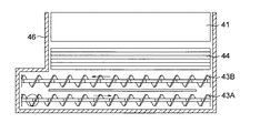
(実施の形態1)
図2には本実施例の現像装置4の側断面図を示し、図3には平面配置図を示している。本実施形態の請求項1記載の現像装置4は、感光体1に対向して位置した現像剤搬送体41の後方に現像剤搬送体軸方向に現像剤を搬送する搬送スクリュ43A、43Bと、更に後方の搬送スクリュ43Aの後方に現像剤搬送体軸方向への搬送力を持たないで現像剤の攪拌を行う攪拌部材42が設けられている。更に本実施例においては現像剤搬送体41と搬送スクリュ43Bとの間には軸方向への現像剤搬送力を持たない現像剤供給部材44を設け、現像剤搬送体41周面上の現像を終えた現像剤に代えて新しい現像剤の供給を行っている。
【0049】
現像剤を現像剤搬送体41へと供給する水車状をなした現像剤供給部材44は4〜8枚程度の放射状の羽根を有している。羽根は3枚以下では現像剤の供給性能は低下し、9枚以上では現像剤へのストレスが増加し、現像剤劣化を招く傾向にある。本実施例では外径40mmで現像剤搬送体41との線速比は0.5〜1.0に設定している。線速比が0.5以下では現像剤の搬送性が不足する傾向にあり、線速比が1.0以上の場合にはストレス増加による現像剤劣化が増加することが認められる。現像剤搬送体41との間隔は1mm〜5mmにあることを適当としている。1mm以下だとストレスは増加し、5mm以上だと搬送性能は低下する。
【0050】
搬送スクリュ43A、43Bは図4に示す本実施例では同形の部材を使用している。本実施例では外径24mmスクリュピッチp16mmのものを使用している。現像剤搬送体41との線速比は0.5〜1.5の間に設定している。線速比が0.5以下においては左右に濃度差が生じるようになり、線速比1.5以上では攪拌性能が確保できない。スクリュピッチpは10mm〜25mmの間のものが用いられる。スクリュピッチpが10mm以下では現像剤濃度に左右差が生じる。またスクリュピッチpが25mm以上では現像剤搬送中に攪拌性能を充分に確保することができなくなる。搬送スクリュ43Bと現像剤供給部材44との間隔は1mm〜5mmの間を適当とする。間隔が1mm以下だとストレスは増加し、間隔が5mm以下だと現像剤の搬送性能は低下する。また搬送スクリュ43A、43B間での間隔は1mm〜5mmの間に設定している。間隔が1mm以下だとストレスが増加し、5mm以上だと両者の間での現像剤の受け渡し能力が低下する。
【0051】
攪拌部材42は、放射状に板材を回転軸に取り付けた水車型あるいは図5(a)に示すような平行な板状部材を回転軸に取り付けた串刺し型が用いられる。何れの型方式による場合も外径24mm見当で、現像剤搬送体41との線速比は1〜2の間に設定している。線速比が1以下の場合には充分な攪拌性能を得ることができない。また線速比が2以上の場合にはストレスの増加が認められる。攪拌部材42が水車型の場合には放射状に植設された羽根数は4〜8枚を適当とし、羽根数は3枚以下では充分な現像剤攪拌性能を得ることができない。また、羽根数が9枚以上の場合にはストレスが増加してしまう。
【0052】
攪拌部材42として本実施例では串刺し型を用いている。略平行に傾いて取り付けられた複数の板状部材421は間隔xとして12〜24mmの間の間隔として、傾き角度θとして30°〜60°の角度をもって回転軸に固設されている。傾き角度θが60°以上の場合には現像剤の攪拌性能が低下するので、間隔xを狭く設定することが必要となる。また角度θが30°以下の場合には間隔xを広く設定してもストレスが増加して来る。本実施例では角度θとして45°、間隔xとして20mmに設定して良好な攪拌結果を得ている。なお板状部材421としては、軸方向への投影面が円形の楕円板が好ましく用いられる。図5(b)には本実施例で板状部材421として使用している楕円板の形状を示している。
【0053】
攪拌部材42と搬送スクリュ43との間隔は1mm〜5mmの間に設定することが好ましい。かかる間隔が設定されていることによって、搬送スクリュ43によって搬送される現像剤に対して攪拌部材42からの攪拌された現像剤が適度に供給されることとなる。なお、攪拌部材42は搬送スクリュ43と同長である必要はなく、次に説明する新トナーの補給位置前後をカバーする長さを有していることによって本発明の効果を奏することができる。
【0054】
本実施例においては現像装置4内の搬送スクリュ43Bに対向した位置に、現像剤の透磁率を検出してトナー濃度を検出する透磁率センサ(Lセンサ)200が設置されていて、トナー濃度の検出が行われている。透磁率センサ200は、磁性キャリアと非磁性トナーの混合比率を見掛け透磁率として検出し、アナログ又はデジタルの電気信号として出力する。現像装置4では現像によって消費されるトナーに対して新トナー及びリサイクルトナーの補給がなされて、現像装置4内では例えば4.5質量%のトナー濃度が維持されるよう制御がなされている。
【0055】
現像装置4の上方には新トナー(NT)を蓄える新トナーホッパ49が設けられていて、その下部には新トナーの現像装置4への供給を行う供給バルブ491が設けられていて、トナー濃度値が所定の濃度値以下に低下したと検知すると、所定量の新トナーが新トナーホッパ49から現像装置4に補給される。
【0056】
本実施形態においては、新トナーの補給位置は、後方に位置した搬送スクリュ43Aと攪拌部材42との略中間位置としていて、外殻46の上面に設けた落下口46Aから新トナー及びリサイクルトナーは落下する構造となっている。新トナー及びリサイクルトナーは搬送スクリュ43Aで搬送される現像剤と攪拌部材42で攪拌された現像剤とが合流する箇所に落下し、攪拌されながら搬送されることとなるので、新トナーやリサイクルトナーは充分な帯電状態に保たれてキャリア粒子外周に付着し、現像剤搬送体41へと移動して現像が行われることとなる。
【0057】
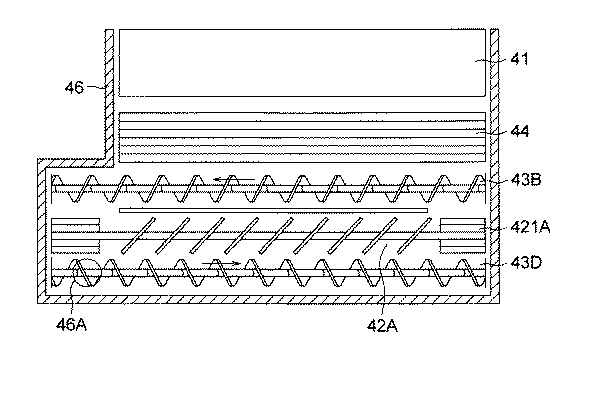
(実施の形態2)
図6には本実施例の現像装置4の側断面図を示し、図7には平面配置図を示している。本実施形態の請求項6記載の現像装置4は、感光体1に対向して位置した現像剤搬送体41の後方に現像剤搬送体軸方向に現像剤を搬送する2本の搬送スクリュ43B、43Dと、搬送スクリュ43B、43Dの間にあって現像剤搬送体軸方向への搬送力を持たないで現像剤の攪拌を行う攪拌部材42Aが設けられている。更に本実施例においては現像剤搬送体41と搬送スクリュ43Bとの間には軸方向への現像剤搬送力を持たない現像剤供給部材44を設け、搬送スクリュ43Bから排出される新しい現像剤を現像剤搬送体41へと供給している。実施の形態1で説明したのと同一機能をもった部材については、同一符号をもって表示し、説明を省略する。
【0058】
2本の搬送スクリュ43B、43Dについて、搬送スクリュ43Bは実施の形態1で説明したのと全く同じ左方向へのリードを有した搬送スクリュである。一方、搬送スクリュ43Dは他は全く同じであるが右方向へのリードを有した搬送スクリュである。よって、搬送スクリュ43Bと43Dとは同方向に回転しながら現像剤を反対方向に搬送している。
【0059】
本実施例においては、新トナー及びリサイクルトナーは後方の搬送スクリュ43Dの端部近くに落下し補給される構成となっていて、搬送スクリュ43Dによって現像剤上に落下して搬送されるトナーに対して、攪拌部材42Aからの攪拌された現像剤が加わって攪拌搬送され、現像剤は特にストレスを受けることなくトナーは摩擦帯電によって飽和状態にまで帯電がなされ、キャリア粒子周面に付着した状態となる。
【0060】
攪拌部材42Aは搬送スクリュ43B、43Dの間に位置しているので、搬送スクリュ43B、43Dの回転によって、回動する現像剤は攪拌部材42Aの両端部を横切る形で攪拌搬送されることとなる。本実施例では攪拌部材42Aの中間部は攪拌部材42におけると同形状の串刺し型とし、両端部431は水車型としている。現像剤は端部において水車型の攪拌部材により攪拌されて搬送スクリュ間での移動が行われる。但し攪拌部材42Aの形状はかかる形状に限定されるものではない。
【0061】
搬送スクリュ43Bと攪拌部材42Aとの間隔は1mm〜5mmの間に設定し、攪拌部材42Aと搬送スクリュ43Dとの間隔も1mm〜5mmの間に設定している。かかる間隔条件を満たすことによって、攪拌搬送されて飽和状態にまで帯電がなされた新トナーやリサイクルトナーはキャリア粒子周面に付着した状態となって回動し、搬送スクリュ43Bによる搬送から外れて現像剤供給部材44へと移動し、現像に用いられることとなる。
【0062】
(3) 図2、図3によって示した実施の形態1の現像装置(実施例1)と、図6、図7によって示した実施の形態2の現像装置(実施例2)とにつき性能テストを行っている。この際比較検討のため、実施例1の現像装置について攪拌部材42を取り除いた図8に示す構成とした現像装置(比較例1)と、実施例1の現像装置について攪拌部材42に代えて搬送スクリュとし、帰還回路43Rを追加して3本の搬送スクリュ43A、43B、43Cによって攪拌搬送する構成とした図9に示す現像装置(比較例2)とを用いて比較検討を行っている。
【0063】
テストを行う現像装置は何れも図1に示した画像形成装置に装着しテストを行っている。テストは新現像剤を装填し、機内を清掃した状態で、次の4テスト項目について、各100kcプリント宛のテストを行い、機内特に転写分離極近傍でのトナー飛散の状況と、現像に基づいて生じるプリント画像の良否を○×をもって評価した。
【0064】
テスト(1) はがきサイズ 黒化率1%相当の原稿
テスト(2) はがきサイズ 黒化率40%相当の原稿
テスト(3) A3サイズ 黒化率1%相当の原稿
テスト(4) A3サイズ 黒化率40%相当の原稿
【0065】
【表1】
比較例1については、黒化率40%原稿テスト(2)及びテスト(4)については補充された新トナーに対する攪拌不足が原因と思われるトナー飛散が認められた。またテスト(1)については現像剤中でのリサイクルトナーの比率が高くなり、リサイクルトナーに対する攪拌不足が原因と思われるトナー飛散が認められた。
【0067】
比較例2については、比較例1と比較し現像剤の攪拌搬送を行う搬送スクリュが1本増えただけ攪拌性能が向上していることが認められた。しかし、黒化率40%の原稿、テスト(2)及びテスト(4)についてはトナー飛散は許容値以上のものであった。
【0068】
一方、実施例1及び実施例2については、原稿サイズや原稿の黒化率には関係なく、転写分離極近傍におけるトナー飛散は少なく、画像不良の発生も認められなかった。
【0069】
【発明の効果】
請求項1〜3記載の発明によれば、現像装置の構成として現像剤搬送体の後方に少なくとも2本の搬送スクリュと、更にその後方に攪拌部材を設けた構成とし、攪拌部材を、回転可能な軸に、所定の角度だけ回転させた、前記軸方向への投影面が円形の楕円板を複数枚、所定の間隔で略平行に固設したものとし、トナー補給を行う補給位置を最も後方に位置した前記搬送スクリュの端部近くの位置とすることによって、落下トナーは搬送スクリュによって搬送される過程においてトナーには飽和状態の帯電がなされて、現像に際してはトナー飛散やコボレが生じることなく良好な現像が行われることとなる。
【0070】
請求項4〜6記載の発明によれば、現像装置の構成として現像剤搬送体の後方に2本の搬送スクリュとその間に攪拌部材を設けた構成とし、攪拌部材を、回転可能な軸に、所定の角度だけ回転させた、前記軸方向への投影面が円形の楕円板を複数枚、所定の間隔で略平行に固設したものとし、トナー補給を行う補給位置を最も後方に位置した前記搬送スクリュの端部近くの位置とすることによって、落下トナーは搬送スクリュによって、搬送される過程においてトナーには飽和状態の帯電がなされて、現像に際してはトナー飛散やコボレが生じることなく良好な現像が行われることとなる。
【0071】
請求項7記載の発明によれば、像担持体と、像担持体上の静電潜像を2成分現像剤を用いて顕像化する現像装置と、該顕像を転写紙上に転写する転写装置と、像担持体上のトナーをクリーニングするクリーニング装置とを有する画像形成装置においても、請求項1〜3記載の現像装置を使用することによって、トナー飛散やコボレ等の現象が生じることなく良好な画質の画像形成が行われるようになる。
【0072】
請求項8記載の発明によれば、像担持体と、像担持体上の静電潜像を2成分現像剤を用いて顕像化する現像装置と、該顕像を転写紙上に転写する転写装置と、像担持体上のトナーをクリーニングするクリーニング装置とを有する画像形成装置においても、請求項4〜6記載の現像装置を使用することによって、トナー飛散やコボレ等の現象が生じることなく良好な画質の画像形成が行われるようになる。
【図面の簡単な説明】
【図1】画像形成装置の断面構成図。
【図2】現像装置(実施の形態1)の側断面図。
【図3】現像装置(実施の形態1)の平面配置図。
【図4】搬送スクリュの外形図。
【図5】攪拌部材の外形図及び板状部材形状。
【図6】現像装置(実施の形態2)の側断面図。
【図7】現像装置(実施の形態2)の平面配置図。
【図8】現像装置(比較例1)の平面配置図。
【図9】現像装置(比較例2)の平面配置図。
【符号の説明】
1 感光体
4 現像装置
41 現像剤搬送体
42 攪拌部材
42A 攪拌部材
43A(B、C、D) 搬送スクリュ
44 現像剤供給部材[0001]
BACKGROUND OF THE INVENTION
The present invention relates to a developing device that visualizes an electrostatic latent image on an image carrier using a two-component developer, and an image forming apparatus such as a copying machine and a printer using the developing device.
[0002]
[Prior art]
In a conventional image forming apparatus such as a copying machine, an electrostatic latent image is formed by exposure based on image data formed by irradiating an image carrier with laser light, and the formed latent image is converted into toner. Then, the image is transferred to a sheet and heat-fixed to form an image. Development of the image forming apparatus visualizes an electrostatic latent image formed on an image carrier using a one-component developer or a two-component developer composed of toner and a carrier.
[0003]
In the case of using a two-component developer, the developer is magnetically attracted by a developer conveying body in which a rotatable sleeve is disposed on the outer periphery of a plurality of magnetic poles fixed at positions provided around the image carrier. The magnetic brush is conveyed to the image carrier by the rotation of the sleeve. The magnetic brush conveyed to the image carrier is visualized by attaching toner according to the potential of the latent image formed on the image carrier. The developer after the completion of development is collected and used again for development together with the toner properly supplied from the outside. In order to form a stable toner image, the developer used in such a configuration needs to maintain a constant toner amount (toner concentration) and a charge amount for adhering according to the potential of the latent image. The toner density is determined by the distribution of the toner consumed in the development and the replenishment toner, and the charge amount of the toner is determined by the friction when the carrier and the toner are mixed. Therefore, the developing device sufficiently stirs the developer composed of toner and carrier to make the toner density distribution uniform and saturate the charge amount applied to the toner to stabilize the toner image.
[0004]
Insufficient charge amount of toner not only causes defects on the image but also contaminates the inside of the machine due to the phenomenon of toner scattering and blurring. This phenomenon is particularly likely to occur in an image forming apparatus that employs a toner recycling system.
[0005]
As a method of sufficiently stirring the carrier and the toner in the developing device so as to obtain a good charged state, for example, in Patent Document 1 and Patent Document 2, 3 is used to transport and supply the developer to the developer transport body. Patent Document 3 describes that a paddle member having a large number of protrusions on the surface and a stirring roll in which a disk-like member is attached in a skewered manner with respect to the shaft are described. The use is described.
[0006]
[Patent Document 1]
Japanese Patent Laid-Open No. 3-194572
[0007]
[Patent Document 2]
JP 2001-249545 A
[0008]
[Patent Document 3]
Japanese Patent Laid-Open No. 5-134540
[0009]
[Problems to be solved by the invention]
Although the above proposal is effective in preventing toner scattering and blurring, it is not sufficient to satisfy all the various image conditions. For example, if a chart having a small original size is continuously printed or a chart having an extremely low blackening rate is continuously printed, the developer is deteriorated and toner scattering tends to occur. On the other hand, if a chart with a high blackening rate is continuously printed, the charge amount of the developer cannot be fully raised and the development is performed, causing toner scattering.
[0010]
The inventors of the present invention have studied the actual state of agitating and conveying the developer in the developing device. In a conventional developing apparatus, a method in which new toner or recycled toner falls on a conveying screw and is stirred and conveyed is often used. The dropped toner is sandwiched between the screws and moved by one lead during one rotation of the conveying screw, and during that time, the developer is agitated. Since the developer in the screw is already in a state where the toner has adhered to the carrier, the developer is in an extremely toner-rich state due to the dropped toner in the transport screw, which is sufficient during the transport of the developer by the transport screw. There is no frictional charging.
[0011]
In the present invention, in a process in which the dropped toner is transported together with the developer in the transport screw, the dropped toner is sufficiently contacted and stirred with the developer, and the developer transport body is in a state in which the triboelectric charge is excellent. It is an object of the present invention to provide a developing device which can be supplied to the printer and can perform good image formation without causing toner scattering or blurring, and an image forming apparatus having such a developing device.
[0012]
[Means for Solving the Problems]
In order to solve the above-described problems and achieve the object, the developing device and the image forming apparatus of the present invention are configured as follows.
[0013]
1. A developer carrier that rotates opposite to the image carrier and conveys the two-component developer to the development region to visualize the electrostatic latent image;
At least two transport screws behind the developer transport body for transporting the developer in the developer transport body axial direction;
Furthermore, in the developing device having a stirring member that is behind the transport screw and stirs the developer without having a transport force in the developer transport body axial direction.
The agitating member is formed by rotating a plurality of elliptical plates each having a circular projection surface in the axial direction, which are rotated on a rotatable shaft by a predetermined angle, and are fixed substantially in parallel at predetermined intervals.The
The replenishment position for toner replenishment is a position near the end of the conveying screw located at the rearmost position.A developing device.
[0014]
2. in frontA developer supply member that does not have developer transport force in the axial direction is provided between the developer transport body and the transport screw.Said2. The developing device according to 1.
[0016]
3. The said predetermined angle is 30 degrees-60 degrees, The said 1 characterized by the above-mentionedOr 2The developing device according to 1.
[0017]
4. A developer carrier that rotates opposite to the image carrier and conveys the two-component developer to the development region to visualize the electrostatic latent image;
Two transport screws behind the developer transport body for transporting the developer in the developer transport body axial direction;
Further, in a developing device having a stirring member that is between the two transport screws and stirs the developer without having a transport force in the developer transport body axial direction.
The agitating member is formed by rotating a plurality of elliptical plates each having a circular projection surface in the axial direction, which are rotated on a rotatable shaft by a predetermined angle, and are fixed substantially in parallel at predetermined intervals.The
The replenishment position for toner replenishment is a position near the end of the conveying screw located at the rearmost position.A developing device.
[0019]
5. A developer supply member having no developer transport force in the axial direction is provided between the developer transport body and the transport screw.4The developing device according to 1.
[0021]
6. The predetermined angle is 30 ° to 60 °.4 or 5The developing device according to any one of the above.
[0022]
7. An image carrier, a developing device that visualizes the electrostatic latent image on the image carrier using a two-component developer, a transfer device that transfers the developed image onto transfer paper, and a toner on the image carrier. In an image forming apparatus having a cleaning device for cleaning,
The developing device,A developer transport body that rotates opposite to the image carrier and transports the two-component developer to the development area to visualize the electrostatic latent image, and a developer transport body shaft that is behind the developer transport body and A developer supply member that does not have a developer transport force in the direction, at least two transport screws behind the developer supply member that transport the developer in the developer transport body axial direction, and the transport screw And a stirring member that stirs the developer without having a transport force in the developer transport body axial direction.
The stirring member is a rotatable shaft rotated by a predetermined angle, and a plurality of elliptical plates each having a circular projection surface in the axial direction are fixed substantially in parallel at predetermined intervals.
An image forming apparatus characterized in that a replenishing position for replenishing toner is a developing device located at a substantially intermediate position between the conveying screw located at the rearmost position and the stirring member.
[0023]
8. An image carrier, a developing device that visualizes the electrostatic latent image on the image carrier using a two-component developer, a transfer device that transfers the developed image onto transfer paper, and a toner on the image carrier. In an image forming apparatus having a cleaning device for cleaning,
The developing device,A developer transport body that rotates opposite to the image carrier and transports the two-component developer to the development area to visualize the electrostatic latent image, and a developer transport body shaft that is behind the developer transport body and A developer supply member that does not have a developer transport force in the direction, at least two transport screws that are behind the developer supply member and transport the developer in the developer transport body axial direction, and two more A stirring member that is between the transport screws and that stirs the developer without having a transport force in the developer transport body axial direction;
The stirring member is a rotatable shaft rotated by a predetermined angle, and a plurality of elliptical plates each having a circular projection surface in the axial direction are fixed substantially in parallel at predetermined intervals.
An image forming apparatus, wherein a replenishing position for replenishing toner is a developing device located near the end on the upstream side in the developer conveying direction of the conveying screw located at the rearmost position.
[0030]
DETAILED DESCRIPTION OF THE INVENTION
The image forming apparatus of the present invention will be described with reference to the drawings.
[0031]
(1) The image forming apparatus shown in the cross-sectional configuration diagram of FIG. 1 illustrates an image forming unit of a copying machine using an electrophotographic process for forming a monochrome image using the developing device of the present invention. However, the present invention is not limited to the configuration shown in FIG.
[0032]
Reference numeral 1 denotes a drum-shaped photoconductor of an image carrier, which is a negatively charged organic semiconductor layer in which a phthalocyanine pigment dispersed in polycarbonate is coated on a grounded metal cylindrical substrate, and is used for charge transport. The photosensitive layer including the layer has a film thickness of 30 μm, and is driven to rotate at a peripheral speed (Vp) of 500 mm / s in the direction of the arrow with a drum diameter of φ100 mm.
[0033]
Reference numeral 2 denotes a scorotron charging means for uniformly charging the periphery of the rotating photosensitive member 1 to a predetermined polarity and potential. The distance between the wire and the grid is 7.5 mm, the distance between the grid and the photosensitive member is 1 mm, and the distance between the wire and the back plate. It has a 12 mm band electrode configuration, a grid applied voltage is −730 V, a bias voltage is applied with a charging current value of −800 μA, and a charging potential of the photoreceptor 1 is −750 V.
[0034]
Reference numeral 3 denotes an image exposure means using a laser scanning system, which uses a semiconductor laser (LD) having a laser wavelength of 780 nm, and its output power is 500 μW. The image exposure means 3 emits a laser beam and scans and exposes the uniformly charged surface of the photoreceptor 1 to form an electrostatic latent image.
[0035]
As will be described in detail later, the developing device 4 develops the electrostatic latent image on the photoreceptor 1 as a toner image by a
[0036]
As a toner of a two-component developer containing a nonmagnetic toner and a magnetic carrier, a polymerized toner having a volume average particle diameter of 3 to 9 μm, and in this embodiment, 6 μm is used. By using the polymerized toner, an image forming apparatus having a high resolving power and a stable density and a very small occurrence of fog can be realized.
[0037]
The polymerized toner is manufactured by the following manufacturing method.
The formation of the binder resin for toner and the toner shape are obtained by polymerization of the raw material monomer or prepolymer of the binder resin and subsequent chemical treatment. More specifically, it is obtained through a polymerization reaction such as suspension polymerization or emulsion polymerization and, if necessary, a step of fusing particles between them, and in the polymerization toner, the raw material monomer or prepolymer is uniformly dispersed in an aqueous system. Since the toner is subsequently polymerized, a spherical toner having a uniform toner particle size distribution and shape can be obtained.
[0038]
If the toner has a volume average particle size of less than 3 μm, fogging and toner scattering are likely to occur. The upper limit of 9 μm is the upper limit of the particle size that enables the high image quality targeted by the present embodiment to be formed.
[0039]
As the carrier, a ferrite core carrier made of magnetic particles having a volume average particle size of 30 to 65 μm and a magnetization of 20 to 70 emu / g is preferable. Carrier adhesion tends to occur with a carrier having a particle size smaller than 30 μm. In addition, a carrier having a particle diameter larger than 65 μm may not form a uniform density image.
[0040]
Reference numeral 5 denotes a pre-transfer exposure light source for irradiating in order to improve the transferability of the toner image.
[0041]
[0042]
[0043]
The transfer paper P fed from the paper feed unit is fed in synchronism with the toner image formed on the photosensitive member 1 by the
[0044]
The fixing
[0045]
On the other hand, the toner remaining on the surface of the photoreceptor 1 after the transfer of the toner image onto the transfer paper P is cleaned by the cleaning device 8. In this embodiment, a blade made of urethane rubber is used as the cleaning means, and the cleaning blade is a counter type for cleaning by sliding on the circumferential surface of the photosensitive member 1. The peripheral surface of the photosensitive member 1 whose surface has been cleaned by passing through the cleaning device 8 is irradiated by a pre-charge exposure (PCL) means 9 using a light wavelength of 700 nm and a light output of 10 lux light source, and the residual potential is lowered to the next. Shift to the image forming cycle.
[0046]
The toner collected by the cleaning device 8 is collected by the developing device 4 by toner recycling means 81 that conveys the toner using a conveying screw or the like. The collecting operation to the developing device 4 is performed concurrently with the rotating operation of the photosensitive member 1.
[0047]
(2) Next, the developing device 4 installed in the image forming apparatus described with reference to FIG. 1 and performing development will be described.
[0048]
(Embodiment 1)
FIG. 2 is a side sectional view of the developing device 4 of the present embodiment, and FIG. 3 is a plan layout view. The developing device 4 according to claim 1 of the present embodiment includes
[0049]
The
[0050]
The conveying
[0051]
As the stirring
[0052]
In this embodiment, a skewer type is used as the stirring
[0053]
The distance between the agitating
[0054]
In this embodiment, a magnetic permeability sensor (L sensor) 200 for detecting the magnetic permeability of the developer and detecting the toner density is installed at a position facing the conveying
[0055]
A
[0056]
In the present embodiment, the replenishment position of the new toner is a substantially intermediate position between the conveying
[0057]
(Embodiment 2)
FIG. 6 shows a side sectional view of the developing device 4 of the present embodiment, and FIG. 7 shows a plan layout view. The developing device 4 according to
[0058]
Regarding the two conveying
[0059]
In this embodiment, the new toner and the recycled toner are dropped and replenished near the end of the rear conveying screw 43D, and the toner dropped onto the developer by the conveying screw 43D is supplied to the toner. Then, the stirred developer from the stirring
[0060]
Since the agitating
[0061]
The distance between the conveying
[0062]
(3) A performance test was conducted between the developing device of the first embodiment shown in FIGS. 2 and 3 (Example 1) and the developing device of the second embodiment shown in FIGS. 6 and 7 (Example 2). Is going. At this time, for comparison, the developing device (Comparative Example 1) in which the stirring
[0063]
Each developing device to be tested is mounted on the image forming apparatus shown in FIG. The test is conducted with the new developer loaded and the inside of the machine cleaned, and the following four test items are tested for each 100 kc print. Based on the state of toner scattering inside the machine, particularly near the transfer separation pole, and development. The quality of the resulting printed image was evaluated with ◯ ×.
[0064]
Test (1) Postcard size Original with 1% blackening rate
Test (2) Postcard size Document with a blackening rate equivalent to 40%
Test (3) A3 size Document with blackening rate equivalent to 1%
Test (4) A3 size Document with blackening rate equivalent to 40%
[0065]
[Table 1]
In Comparative Example 1, toner scattering, which is considered to be caused by insufficient stirring of the replenished new toner, was observed in the original test (2) and test (4) with a blackening rate of 40%. In Test (1), the ratio of recycled toner in the developer was high, and toner scattering that was thought to be caused by insufficient stirring with respect to the recycled toner was observed.
[0067]
In Comparative Example 2, it was recognized that the stirring performance was improved by one more transport screw for stirring and transporting the developer than in Comparative Example 1. However, the toner scattering for the original with a blackening rate of 40%, Test (2) and Test (4) was more than the allowable value.
[0068]
On the other hand, in Examples 1 and 2, there was little toner scattering in the vicinity of the transfer separation pole, and no image defect was observed regardless of the document size or the blackening rate of the document.
[0069]
【The invention's effect】
Claims 1 to3According to the described invention, the developing device has a configuration in which at least two transport screws are provided behind the developer transport body, and a stirring member is further provided behind the developer transport body. A plurality of elliptical plates with a circular projection surface in the axial direction, which are rotated by an angle ofThe replenishment position for toner replenishment is the position near the end of the conveying screw located at the rearmost position.As a result, in the process in which the fallen toner is conveyed by the conveyance screw, the toner is charged in a saturated state, and good development is performed without causing toner scattering or blurring during development.
[0070]
Claim4~6According to the described invention, the developing device has a configuration in which two conveying screws and a stirring member are provided behind the developer conveying member, and the stirring member is rotated by a predetermined angle about a rotatable shaft. A plurality of elliptical plates each having a circular projection surface in the axial direction fixed substantially in parallel at a predetermined interval;The replenishment position for toner replenishment is the position near the end of the conveying screw located at the rearmost position.As a result, the fallen toner is charged in a saturated state in the process of being conveyed by the conveying screw, and good development is performed without causing toner scattering or blurring during development.
[0071]
Claim7According to the described invention, the image carrier, the developing device that visualizes the electrostatic latent image on the image carrier using the two-component developer, the transfer device that transfers the developed image onto the transfer paper, An image forming apparatus having a cleaning device for cleaning toner on the image carrier is also disclosed in claims 1 to 3.3By using the developing device described above, it is possible to form an image with good image quality without causing toner scattering or blurring.
[0072]
Claim8According to the described invention, the image carrier, the developing device that visualizes the electrostatic latent image on the image carrier using the two-component developer, the transfer device that transfers the developed image onto the transfer paper, An image forming apparatus having a cleaning device for cleaning toner on the image carrier.4~6By using the developing device described above, it is possible to form an image with good image quality without causing toner scattering or blurring.
[Brief description of the drawings]
FIG. 1 is a cross-sectional configuration diagram of an image forming apparatus.
FIG. 2 is a side sectional view of a developing device (Embodiment 1).
FIG. 3 is a plan layout view of a developing device (Embodiment 1).
FIG. 4 is an external view of a conveying screw.
FIG. 5 is an external view of a stirring member and a plate-like member shape.
FIG. 6 is a side sectional view of a developing device (Embodiment 2).
FIG. 7 is a plan layout view of a developing device (Embodiment 2).
FIG. 8 is a plan layout view of a developing device (Comparative Example 1).
FIG. 9 is a plan layout view of a developing device (Comparative Example 2).
[Explanation of symbols]
1 Photoconductor
4 Development device
41 Developer transport body
42 Stirring member
42A Stirring member
43A (B, C, D) Conveying screw
44 Developer supply member
Claims (8)
該現像剤搬送体の後方にあって現像剤搬送体軸方向に現像剤を搬送する少なくとも2本の搬送スクリュと、
更に該搬送スクリュの後方にあって、現像剤搬送体軸方向への搬送力を持たないで現像剤の攪拌を行う攪拌部材とを有する現像装置において、
前記攪拌部材は、回転可能な軸に、所定の角度だけ回転させた、前記軸方向への投影面が円形の楕円板を複数枚、所定の間隔で略平行に固設したものであり、
トナー補給を行う補給位置は、最も後方に位置した前記搬送スクリュと前記攪拌部材の略中間位置であることを特徴とする現像装置。A developer carrier that rotates opposite to the image carrier and conveys the two-component developer to the development region to visualize the electrostatic latent image;
At least two transport screws behind the developer transport body for transporting the developer in the developer transport body axial direction;
Furthermore, in the developing device having a stirring member that is behind the transport screw and stirs the developer without having a transport force in the developer transport body axial direction.
The stirring member is a rotatable shaft, rotated by a predetermined angle, plural projection plane circular elliptical plate to said axial state, and are not fixedly provided substantially in parallel at predetermined intervals,
Supply position for toner replenishment to a developing device which is characterized substantially intermediate position der Rukoto the rearmost to the conveying screw positioned at the agitating member.
該現像剤搬送体の後方にあって現像剤搬送体軸方向に現像剤を搬送する2本の搬送スクリュと、 Two transport screws behind the developer transport body for transporting the developer in the developer transport body axial direction;
更に2本の前記搬送スクリュの間にあって、現像剤搬送体軸方向への搬送力を持たないで現像剤の攪拌を行う攪拌部材とを有する現像装置において、 Further, in a developing device having a stirring member that is between the two transport screws and stirs the developer without having a transport force in the developer transport body axial direction.
前記攪拌部材は、回転可能な軸に、所定の角度だけ回転させた、前記軸方向への投影面が円形の楕円板を複数枚、所定の間隔で略平行に固設したものであり、 The stirring member is a rotatable shaft rotated by a predetermined angle, and a plurality of elliptical plates each having a circular projection surface in the axial direction are fixed substantially in parallel at predetermined intervals.
トナー補給を行う補給位置は、最も後方に位置した前記搬送スクリュの端部近くの位置であることを特徴とする現像装置。 2. A developing device according to claim 1, wherein a replenishing position for replenishing toner is a position near an end of the conveying screw located at the rearmost position.
前記現像装置は、像担持体に対向し回転して2成分現像剤を現像領域へと搬送し静電潜像を顕像化する現像剤搬送体と、該現像剤搬送体の後方にあって現像剤搬送体軸方向への現像剤搬送力を持たない現像剤供給部材と、該現像剤供給部材の後方にあって現像剤搬送体軸方向に現像剤を搬送する少なくとも2本の搬送スクリュと、更に該搬送スクリュの後方にあって、現像剤搬送体軸方向への搬送力を持たないで現像剤の攪拌を行う攪拌部材と、を有していて、 The developing device rotates opposite to the image carrier, conveys the two-component developer to the development area, and visualizes the electrostatic latent image, and is located behind the developer carrier. A developer supply member that does not have developer transport force in the developer transport body axial direction, and at least two transport screws that are behind the developer supply member and transport the developer in the developer transport body axial direction; And a stirring member that is behind the transport screw and stirs the developer without having a transport force in the developer transport body axial direction,
前記攪拌部材は、回転可能な軸に、所定の角度だけ回転させた、前記軸方向への投影面が円形の楕円板を複数枚、所定の間隔で略平行に固設したものであり、 The stirring member is a rotatable shaft rotated by a predetermined angle, and a plurality of elliptical plates each having a circular projection surface in the axial direction are fixed substantially in parallel at predetermined intervals.
トナー補給を行う補給位置は、最も後方に位置した前記搬送スクリュと前記攪拌部材の略中間位置とした現像装置であることを特徴とした画像形成装置。 An image forming apparatus characterized in that a replenishing position for replenishing toner is a developing device located at a substantially intermediate position between the conveying screw located at the rearmost position and the stirring member.
前記現像装置は、像担持体に対向し回転して2成分現像剤を現像領域へと搬送し静電潜像を顕像化する現像剤搬送体と、該現像剤搬送体の後方にあって現像剤搬送体軸方向への現像剤搬送力を持たない現像剤供給部材と、該現像剤供給部材の後方にあって現像剤搬送体軸方向に現像剤を搬送する少なくとも2本の搬送スクリュと、更に2本の前記搬送スクリュの間にあって、現像剤搬送体軸方向への搬送力を持たないで現像剤の攪拌を行う攪拌部材と、を有していて、 The developing device rotates opposite to the image carrier, conveys the two-component developer to the development area, and visualizes the electrostatic latent image, and is located behind the developer carrier. A developer supply member that does not have developer transport force in the developer transport body axial direction, and at least two transport screws that are behind the developer supply member and transport the developer in the developer transport body axial direction; And a stirring member that is between the two transport screws and stirs the developer without having a transport force in the developer transport body axial direction,
前記攪拌部材は、回転可能な軸に、所定の角度だけ回転させた、前記軸方向への投影面が円形の楕円板を複数枚、所定の間隔で略平行に固設したものであり、 The stirring member is a rotatable shaft rotated by a predetermined angle, and a plurality of elliptical plates each having a circular projection surface in the axial direction are fixed substantially in parallel at predetermined intervals.
トナー補給を行う補給位置は、最も後方に位置した前記搬送スクリュの現像剤搬送方向上流側の端部近くの位置とした現像装置であることを特徴とした画像形成装置。 An image forming apparatus, wherein a replenishing position for replenishing toner is a developing device located near the end on the upstream side in the developer conveying direction of the conveying screw located at the rearmost position.
Priority Applications (1)
| Application Number | Priority Date | Filing Date | Title |
|---|---|---|---|
| JP2003186920A JP4423890B2 (en) | 2003-06-30 | 2003-06-30 | Developing device and image forming apparatus |
Applications Claiming Priority (1)
| Application Number | Priority Date | Filing Date | Title |
|---|---|---|---|
| JP2003186920A JP4423890B2 (en) | 2003-06-30 | 2003-06-30 | Developing device and image forming apparatus |
Publications (2)
| Publication Number | Publication Date |
|---|---|
| JP2005024621A JP2005024621A (en) | 2005-01-27 |
| JP4423890B2 true JP4423890B2 (en) | 2010-03-03 |
Family
ID=34185924
Family Applications (1)
| Application Number | Title | Priority Date | Filing Date |
|---|---|---|---|
| JP2003186920A Expired - Fee Related JP4423890B2 (en) | 2003-06-30 | 2003-06-30 | Developing device and image forming apparatus |
Country Status (1)
| Country | Link |
|---|---|
| JP (1) | JP4423890B2 (en) |
Families Citing this family (1)
| Publication number | Priority date | Publication date | Assignee | Title |
|---|---|---|---|---|
| KR100739756B1 (en) | 2005-11-17 | 2007-07-13 | 삼성전자주식회사 | Nonmagnetic monocomponent type developing apparatus |
-
2003
- 2003-06-30 JP JP2003186920A patent/JP4423890B2/en not_active Expired - Fee Related
Also Published As
| Publication number | Publication date |
|---|---|
| JP2005024621A (en) | 2005-01-27 |
Similar Documents
| Publication | Publication Date | Title |
|---|---|---|
| JP4642529B2 (en) | Development device | |
| JP2006313307A (en) | Image forming apparatus | |
| JP2005037878A (en) | Development apparatus, image forming apparatus, processing cartridge, and development method | |
| US6892045B2 (en) | Image forming apparatus and convey control method for recycle toner | |
| JPH09288426A (en) | Image forming device | |
| JP2009025700A (en) | Development apparatus and image forming apparatus using the same | |
| JP5463756B2 (en) | Developing device and image forming apparatus | |
| JP4423890B2 (en) | Developing device and image forming apparatus | |
| JP5174568B2 (en) | Developing device and image forming apparatus including the same | |
| JPH0792813A (en) | Developing device | |
| JP2010230752A (en) | Developing device, method of producing developing device, and image forming apparatus | |
| JP2005121774A (en) | Development apparatus and image forming apparatus | |
| JP2004279490A (en) | Image forming apparatus | |
| JP2002323786A (en) | Toner and image forming apparatus | |
| JP2011095377A (en) | Image forming apparatus | |
| JPH1184857A (en) | Image forming device | |
| JP2001125366A (en) | Developing device | |
| JP3846467B2 (en) | Developing device and image forming apparatus | |
| JP3846466B2 (en) | Developing device and image forming apparatus | |
| JP2006138881A (en) | Image forming apparatus and process cartridge | |
| JP4292976B2 (en) | Developing device and image forming apparatus | |
| JPH1144996A (en) | Developing device | |
| JP4122816B2 (en) | Image forming apparatus | |
| JP3849656B2 (en) | Image forming apparatus | |
| JP2010128191A (en) | Developing device, and image forming apparatus with the same |
Legal Events
| Date | Code | Title | Description |
|---|---|---|---|
| A621 | Written request for application examination |
Free format text: JAPANESE INTERMEDIATE CODE: A621 Effective date: 20060612 |
|
| A977 | Report on retrieval |
Free format text: JAPANESE INTERMEDIATE CODE: A971007 Effective date: 20080829 |
|
| A131 | Notification of reasons for refusal |
Free format text: JAPANESE INTERMEDIATE CODE: A131 Effective date: 20080909 |
|
| A131 | Notification of reasons for refusal |
Free format text: JAPANESE INTERMEDIATE CODE: A131 Effective date: 20090303 |
|
| A521 | Written amendment |
Free format text: JAPANESE INTERMEDIATE CODE: A523 Effective date: 20090430 |
|
| A131 | Notification of reasons for refusal |
Free format text: JAPANESE INTERMEDIATE CODE: A131 Effective date: 20090818 |
|
| A521 | Written amendment |
Free format text: JAPANESE INTERMEDIATE CODE: A523 Effective date: 20091014 |
|
| TRDD | Decision of grant or rejection written | ||
| A01 | Written decision to grant a patent or to grant a registration (utility model) |
Free format text: JAPANESE INTERMEDIATE CODE: A01 Effective date: 20091117 |
|
| A01 | Written decision to grant a patent or to grant a registration (utility model) |
Free format text: JAPANESE INTERMEDIATE CODE: A01 |
|
| A61 | First payment of annual fees (during grant procedure) |
Free format text: JAPANESE INTERMEDIATE CODE: A61 Effective date: 20091130 |
|
| R150 | Certificate of patent or registration of utility model |
Free format text: JAPANESE INTERMEDIATE CODE: R150 |
|
| FPAY | Renewal fee payment (event date is renewal date of database) |
Free format text: PAYMENT UNTIL: 20121218 Year of fee payment: 3 |
|
| FPAY | Renewal fee payment (event date is renewal date of database) |
Free format text: PAYMENT UNTIL: 20131218 Year of fee payment: 4 |
|
| S111 | Request for change of ownership or part of ownership |
Free format text: JAPANESE INTERMEDIATE CODE: R313111 |
|
| R350 | Written notification of registration of transfer |
Free format text: JAPANESE INTERMEDIATE CODE: R350 |
|
| LAPS | Cancellation because of no payment of annual fees |