JP4423014B2 - Electric motor for vehicle - Google Patents
Electric motor for vehicle Download PDFInfo
- Publication number
- JP4423014B2 JP4423014B2 JP2003391029A JP2003391029A JP4423014B2 JP 4423014 B2 JP4423014 B2 JP 4423014B2 JP 2003391029 A JP2003391029 A JP 2003391029A JP 2003391029 A JP2003391029 A JP 2003391029A JP 4423014 B2 JP4423014 B2 JP 4423014B2
- Authority
- JP
- Japan
- Prior art keywords
- rotor
- electric motor
- stator
- attached
- ring
- Prior art date
- Legal status (The legal status is an assumption and is not a legal conclusion. Google has not performed a legal analysis and makes no representation as to the accuracy of the status listed.)
- Expired - Lifetime
Links
- 230000002093 peripheral effect Effects 0.000 claims description 45
- 238000005096 rolling process Methods 0.000 claims description 20
- 238000004891 communication Methods 0.000 claims description 19
- XLYOFNOQVPJJNP-UHFFFAOYSA-N water Substances O XLYOFNOQVPJJNP-UHFFFAOYSA-N 0.000 claims description 14
- 238000007789 sealing Methods 0.000 claims description 12
- 239000000498 cooling water Substances 0.000 claims description 7
- 230000005484 gravity Effects 0.000 claims description 7
- 239000000843 powder Substances 0.000 claims description 7
- 239000000314 lubricant Substances 0.000 claims description 3
- 239000000428 dust Substances 0.000 description 8
- XEEYBQQBJWHFJM-UHFFFAOYSA-N Iron Chemical compound [Fe] XEEYBQQBJWHFJM-UHFFFAOYSA-N 0.000 description 6
- 239000000725 suspension Substances 0.000 description 6
- 230000002159 abnormal effect Effects 0.000 description 5
- 230000005540 biological transmission Effects 0.000 description 5
- 230000005856 abnormality Effects 0.000 description 4
- 230000001105 regulatory effect Effects 0.000 description 4
- 229920003051 synthetic elastomer Polymers 0.000 description 4
- 239000005061 synthetic rubber Substances 0.000 description 4
- 239000003638 chemical reducing agent Substances 0.000 description 3
- 239000004519 grease Substances 0.000 description 3
- 238000009434 installation Methods 0.000 description 3
- 229910052742 iron Inorganic materials 0.000 description 3
- 238000000034 method Methods 0.000 description 3
- 230000006866 deterioration Effects 0.000 description 2
- 238000006073 displacement reaction Methods 0.000 description 2
- 230000009977 dual effect Effects 0.000 description 2
- 230000000694 effects Effects 0.000 description 2
- 238000012423 maintenance Methods 0.000 description 2
- 238000009751 slip forming Methods 0.000 description 2
- 238000005452 bending Methods 0.000 description 1
- 230000003139 buffering effect Effects 0.000 description 1
- 238000001816 cooling Methods 0.000 description 1
- 238000010586 diagram Methods 0.000 description 1
- 238000003825 pressing Methods 0.000 description 1
- 238000009423 ventilation Methods 0.000 description 1
Images


Description
本発明は、車両用電動機に関する。 The present invention relates to a car amphibious motor.
電気自動車においては、電動機1台でトランスミッション、デファレンシャルギヤを介してトルクを分配して駆動輪を駆動する方式や、駆動輪に遊星ギヤ等の減速機と電動機を一体的に組み込んだインホイールモータ方式等が提案されている(例えば、特許文献1参照)。 In electric vehicles, a single motor is used to drive the drive wheels by distributing torque via the transmission and differential gear, and an in-wheel motor system in which the drive wheels are integrated with a reduction gear such as a planetary gear and an electric motor. Etc. have been proposed (see, for example, Patent Document 1).
しかし、上記のような電動機1台でデファレンシャルギヤ等を介して駆動輪を駆動する方式では、その動力伝達系による電動機出力の損失が大きいため駆動効率が悪かった。
また、上記インホイールモータ方式では、トランスミッションやデファレンシャルギヤを介することなく駆動輪を駆動するので、駆動効率は大幅に改善される。しかし、当該方式においても、減速機を介して駆動輪を駆動しているので電動機出力の損失は、なお存在していた。
また、このインホイールモータ方式においては、駆動輪に電動機や減速機が一体的に組み込まれているため、車両のサスペンションが路面に応じて上下動した場合、タイヤや車軸と共に、電動機や減速機等も上下動することになる。つまり、サスペンションにおける路面に応じて上下に可動する部分の重量が、電動機や減速機の装着により増加し、いわゆるバネ下重量の増加を招いていた。これにより、サスペンションの路面に対する追従性が低下し、タイヤの接地性と乗り心地性が大幅に悪化するという問題があった。
また、上述のような電動機に使用される軸受ユニットは、通常、電動機内で固定されており、その軸受ユニットの軸受に異常が生じた場合にその交換作業が行い難く、また軸受の点検作業などを実施するのが困難であった。
However, in the method of driving the driving wheels with a single electric motor as described above via a differential gear or the like, the driving efficiency is poor because the loss of the motor output by the power transmission system is large.
Moreover, in the said in-wheel motor system, since a driving wheel is driven without going through a transmission and a differential gear, drive efficiency is improved significantly. However, even in this method, since the drive wheels are driven via the reduction gear, there is still a loss in the motor output.
Further, in this in-wheel motor system, since an electric motor and a speed reducer are integrally incorporated in the drive wheel, when the vehicle suspension moves up and down according to the road surface, the electric motor, the speed reducer, etc. Will also move up and down. In other words, the weight of the portion of the suspension that can move up and down in accordance with the road surface increases due to the mounting of the electric motor and the speed reducer, leading to an increase in the so-called unsprung weight. As a result, the followability of the suspension to the road surface is lowered, and there is a problem that the ground contact property and riding comfort of the tire are greatly deteriorated.
In addition, the bearing unit used in the electric motor as described above is usually fixed in the electric motor, and it is difficult to replace the bearing unit when an abnormality occurs in the bearing of the bearing unit. It was difficult to implement.
本発明はこのような事情に鑑みなされたものであり、軸受に異常などが生じたときでも、その異常な軸受の交換作業などを容易に行うことができ、かつ、電気自動車等の車両の駆動輪に一体的に組み込まれても、タイヤの接地性と乗り心地性を悪化させることがない、駆動効率の高い車両用電動機を提供することを目的とする。 The present invention has been made in view of such circumstances, and even when an abnormality or the like occurs in a bearing, the operation of replacing the abnormal bearing can be easily performed , and driving of a vehicle such as an electric vehicle is possible . be integrated in the wheel, it is not Na worsen the ride comfort and the ground of the tire, and an object thereof is to provide an electric machine having high drive dynamic efficient vehicles.
本発明の車両用電動機は、ステータ及びロータを備え、前記ロータによって車両の駆動輪を回転駆動させる車両用電動機であって、内輪と、外輪と、これら内外輪間に転動自在に設けられた複数の転動体とを備えた転がり軸受を有し、前記ステータの軸方向両端部及び前記ロータの軸方向両端部に、前記内輪及び前記外輪の一方及び他方がそれぞれ取付けられ、前記ステータに対して前記ロータを回転自在に支持する軸受ユニットを備え、前記軸受ユニットは、前記内輪の内周面及び前記外輪の外周面の少なくとも一方の周面に嵌合されるとともに、その軌道輪が取付けられている前記ステータ又は前記ロータに対し着脱可能に固定される円環状のハウジング部材を有し、前記軌道輪は、その周面において、その軸方向の一方側が前記ステータ又は前記ロータ側に形成された環状の取付面に対し着脱可能に取り付けられているとともに、他方側が前記ハウジング部材に嵌合されており、前記軸受ユニットは、さらに、前記内外輪間に取付けられた第一のシール部材と、前記内外輪間の環状開口部を塞ぐように前記ハウジング部材に取付けられた第二のシール部材とを有し、前記両シール部材において被シール面に摺接する摺接部には、当該シール部材の主成分よりも比重の大きい微粉末が混入されていることを特徴としている。
また、本発明の車両用電動機は、円筒状に構成されたロータ及び円筒状に構成され前記ロータに包囲されたステータを備え、車両の駆動輪に連結可能に構成され前記ロータによって前記駆動輪を回転駆動させる車両用電動機であって、内輪と、外輪と、これら内外輪間に転動自在に設けられた複数の転動体とを備えた転がり軸受を有し、前記内輪及び前記外輪が前記ステータの軸方向両端部及び前記ロータの軸方向両端部にそれぞれ取付けられ、前記ステータに対して前記ロータを回転自在に支持する軸受ユニットを備え、前記軸受ユニットは、前記内輪の内周面及び前記外輪の外周面の少なくとも一方の周面に嵌合されるとともに、その軌道輪が取付けられている前記ステータ又は前記ロータに対し着脱可能に固定される円環状のハウジング部材を有し、前記軌道輪は、その周面において、その軸方向の一方側が前記ステータ又は前記ロータ側に形成された環状の取付面に対し着脱可能に取り付けられているとともに、他方側が前記ハウジング部材に嵌合されており、前記軸受ユニットは、さらに、前記内外輪間に取付けられた第一のシール部材と、前記内外輪間の環状開口部を塞ぐように前記ハウジング部材に取付けられた第二のシール部材とを有し、前記第一及び第二のシール部材間には潤滑剤が充填され、前記両シール部材には、被シール面に摺接する摺接部が設けられているとともに、この摺接部には、前記被シール面に対する接触面積を減少させる凹部が形成され、前記シール部材の摺接部には、当該シール部材の主成分よりも比重の大きい微粉末が混入されていることを特徴としている。
上記のように構成された車両用電動機は、前記ステータ及び前記ロータの各軸方向端部に前記軸受ユニットの内輪及び外輪の一方及び他方がそれぞれ取付けられているので、転がり軸受のみが破損した場合に、電動機全体を分解しなくても電動機から当該転がり軸受を前記ハウジング部材とともに着脱させることができ、当該転がり軸受を容易に交換することができる。
The vehicle electric motor of the present invention is a vehicle electric motor that includes a stator and a rotor, and rotationally drives a drive wheel of the vehicle by the rotor, and is provided so as to be able to roll between an inner ring, an outer ring, and the inner and outer rings. has a rolling bearing and a plurality of rolling elements, the axially opposite end portions of the axial end portion and the rotor of the stator, one and the other of the inner ring and the outer ring are attached, respectively, to the stator A bearing unit that rotatably supports the rotor, and the bearing unit is fitted to at least one of the inner circumferential surface of the inner ring and the outer circumferential surface of the outer ring, and the raceway ring is attached to the bearing unit. An annular housing member that is detachably fixed to the stator or the rotor. The raceway has a circumferential surface on one side of the axial direction of the stay. Or while being detachably attached to an annular attachment surface formed on the rotor side, the other side is fitted to the housing member, and the bearing unit is further attached between the inner and outer rings. A sliding contact portion having a first sealing member and a second sealing member attached to the housing member so as to close an annular opening between the inner and outer rings, and slidingly contacting a sealed surface in the both sealing members. Is characterized in that a fine powder having a specific gravity larger than that of the main component of the seal member is mixed therein .
According to another aspect of the present invention, there is provided a vehicular electric motor including a rotor configured in a cylindrical shape and a stator configured in a cylindrical shape and surrounded by the rotor, and configured to be connectable to a drive wheel of a vehicle. An electric motor for a vehicle that is driven to rotate, and includes a rolling bearing including an inner ring, an outer ring, and a plurality of rolling elements provided between the inner and outer rings so as to be capable of rolling, and the inner ring and the outer ring are the stator. The bearing units are respectively attached to both axial ends of the rotor and axially both ends of the rotor, and rotatably support the rotor with respect to the stator. The bearing units include an inner peripheral surface of the inner ring and the outer ring. An annular housing that is fitted to at least one peripheral surface of the outer peripheral surface of the rotor and is detachably fixed to the stator or the rotor to which the race is attached. The raceway has a member, and one of the axial directions of the raceway is detachably attached to an annular attachment surface formed on the stator or the rotor side, and the other side is the housing. The bearing unit is further fitted to the housing member so as to close the first seal member attached between the inner and outer rings and the annular opening between the inner and outer rings. Two sealing members, a lubricant is filled between the first and second sealing members, and both the sealing members are provided with sliding contact portions that are in sliding contact with the surfaces to be sealed, The sliding contact portion is formed with a recess for reducing the contact area with the surface to be sealed, and the sliding contact portion of the seal member is mixed with fine powder having a specific gravity larger than the main component of the seal member. This It is characterized in.
In the vehicular electric motor configured as described above, when one and the other of the inner ring and the outer ring of the bearing unit are respectively attached to the axial ends of the stator and the rotor, only the rolling bearing is damaged. In addition, the rolling bearing can be detached from the electric motor together with the housing member without disassembling the entire electric motor, and the rolling bearing can be easily replaced.
また、上記車両用電動機において、円筒状のステータとロータとから構成される中空の円筒形状としているので、従来例に示した電動機よりも軽量なものとなる。また、減速機を介さずに前記ロータにより駆動輪を直接的に駆動することができることから、駆動効率が高いものとなる。 Further, in the electric machine above the vehicle, since the hollow cylindrical composed of a circular cylindrical stator and a rotor, a lighter than the motor shown in the conventional example. In addition, since the driving wheels can be directly driven by the rotor without using a reduction gear, the driving efficiency is high.
また、上記車両用電動機では、前記軸受ユニットは、前記内外輪間に取付けられた第一のシール部材と、前記環状開口部を塞ぐように前記ハウジング部材に取付けられた第二のシール部材とを有し、前記第一及び第二のシール部材間に潤滑剤を充填しているので、シール部材を潤滑し、その摩耗を抑制することができ、当該シール部材の寿命が向上する。これにより長期に渡って電動機内部への耐防塵、耐水性を維持することができる。 Further, the electric motor for the vehicle, wherein the bearing unit includes a first seal member mounted between said inner and outer rings, and a second seal member attached to said housing member so as to close the annular opening And the lubricant is filled between the first and second seal members, so that the seal member can be lubricated and its wear can be suppressed, and the life of the seal member is improved. Thereby, it is possible to maintain dust resistance and water resistance inside the electric motor for a long time.
また、上記車両用電動機では、前記シール部材には、被シール面に摺接する摺接部が設けられているとともに、この摺接部には、前記被シール面に対する接触面積を減少させる凹部が形成されているので、上記摺接部での接触面積が減少し、高速回転時でも摺接部での動摩擦力が大きくなることを抑制することができ、前記シール部材の寿命を向上させることができる。よって、軸受寿命の向上および電動機内部への耐防塵・耐防水性を維持することができる。 Further, the electric motor for the vehicle, the seal member, with which the sliding contact portion is provided in sliding contact with the object to be sealing surfaces, this sliding contact portion, the concave portion to reduce the contact area with the object seal face formed Therefore, the contact area at the slidable contact portion is reduced, and an increase in dynamic friction force at the slidable contact portion can be suppressed even during high-speed rotation, and the life of the seal member can be improved. . Therefore, it is possible to improve the bearing life and to maintain the dust resistance and waterproof resistance inside the electric motor.
また、上記車両用電動機では、前記シール部材の摺接部には、当該シール部材の主成分よりも比重の大きい微粉末が混入されているので、シール部材の摺接部に作用する遠心力が高められ、ロータの回転速度に応じて摺接部を広げさせることができる。よって、ロータの回転速度に応じて摺接部での接触面圧を変化させることができ、高速回転時でも当該摺接部での動摩擦力の増加を抑えることができる。よって、軸受寿命の向上および電動機内部への耐防塵・耐防水性を維持することができる。 Further, in the above-described vehicle electric motor , fine powder having a specific gravity larger than that of the main component of the seal member is mixed in the sliding contact portion of the seal member, so that a centrifugal force acting on the slide contact portion of the seal member is generated. enhanced et is, it is possible to let spread sliding part according to the rotational speed of the rotor. Therefore, the contact surface pressure at the sliding contact portion can be changed according to the rotational speed of the rotor, and an increase in the dynamic friction force at the sliding contact portion can be suppressed even during high-speed rotation. Therefore, it is possible to improve the bearing life and to maintain the dust resistance and waterproof resistance inside the electric motor.
また、上記車両用電動機において、前記ロータに取付けられた磁石と、この磁石に対向するように前記ステータに配置されたホールICとを有することが好ましい。
このようにすることで、ロータの回転数および回転位置を検出することができるので、車両用電動機の回転数制御が容易になる。
The vehicle electric motor preferably includes a magnet attached to the rotor and a Hall IC disposed on the stator so as to face the magnet.
By doing in this way, since the rotation speed and rotation position of a rotor are detectable, rotation speed control of the motor for vehicles becomes easy.
また、上記車両用電動機において、前記ロータ及び前記ステータの少なくとも一方側に形成され、電動機の内部空間と外部空間とを連通する連通孔と、この連通孔を閉塞し、電動機の内部空間の圧力が所定値以上になると当該連通孔を開放するリリーフ弁とを備えることが好ましい。
このようにすることで電動機の運転に伴う温度上昇によって電動機の内部空間の圧力が高くなった場合に、前記栓部材は、内部空間の空気圧により前記付勢手段の付勢力に抗して弁座から離れるよう押し上げられ、連通孔を開放状態にして当該内部空間の圧力を適度に下げることができる。これにより、電動機の内部の異常な圧力上昇を抑えることができる。
Further, in the vehicle electric motor, a communication hole formed on at least one side of the rotor and the stator and communicating the internal space and the external space of the electric motor, and the communication hole is closed, and the pressure of the internal space of the electric motor is It is preferable to provide a relief valve that opens the communication hole when a predetermined value or more is reached.
In this way, when the pressure in the internal space of the motor becomes high due to a temperature rise associated with the operation of the motor, the plug member resists the urging force of the urging means by the air pressure in the internal space. The pressure in the internal space can be lowered moderately by pushing up away from the air and opening the communication hole. Thereby, the abnormal pressure rise inside an electric motor can be suppressed.
また、上記車両用電動機において、前記ステータの内周面には、冷却水路を備えたウォータージャケットが設けられていることが好ましい。
この場合、高負荷で電動機が運転された場合でも、ウォータージャケットの冷却水路を流れる冷却水によって、電動機の運転に伴う温度上昇を抑え、その温度上昇による電動機の破損等を防止することができる。
In the vehicle electric motor, it is preferable that a water jacket provided with a cooling water channel is provided on the inner peripheral surface of the stator.
In this case, even when the motor is operated with a high load, the cooling water flowing through the cooling water passage of the water jacket can suppress the temperature increase accompanying the operation of the motor and prevent the motor from being damaged due to the temperature increase.
以上のように、上記軸受ユニットは、その転がり軸受が電動機等の装置に対して着脱可能に取付けることができるので、当該転がり軸受に異常などが生じたときでも、その異常な転がり軸受を容易に交換することができる。
また、本発明に係る車両用電動機は、駆動輪と一体に組み込まれた場合にも、バネ下重量の増加を抑制することができるため、タイヤの接地性と乗り心地を悪化させることを抑制できる。また、減速機を介さずに前記ロータにより駆動輪を直接的に駆動することができることから、駆動効率が高いものとなる。
As described above, since the rolling bearing can be detachably attached to a device such as an electric motor, even if an abnormality occurs in the rolling bearing, the abnormal rolling bearing can be easily formed. Can be exchanged.
In addition, the vehicle electric motor according to the present invention can suppress an increase in unsprung weight even when it is integrated with a drive wheel, so that deterioration of tire ground contact and riding comfort can be suppressed. . In addition, since the driving wheels can be directly driven by the rotor without using a reduction gear, the driving efficiency is high.
本発明の好ましい実施形態について添付図面を参照しながら説明する。なお、以下の説明では、電気自動車の駆動源を構成する電動機に適用した場合を例示して説明する。
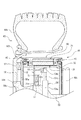
図1は、本発明の第一の実施形態に係る車両用電動機の構成を模式的に示した車軸方向の断面図である。また、図2は、図1中の電動機の一部分を示した円筒軸方向断面図である。
図1において、本実施形態の電動機10は、タイヤ60aとホイール60bとからなる駆動輪60の内部に設けられ、ホイール60bに連結されて駆動輪60を駆動するようになっている。
Preferred embodiments of the present invention will be described with reference to the accompanying drawings. In the following description, a case where the present invention is applied to an electric motor constituting a drive source of an electric vehicle will be described as an example.
Figure 1 is a cross-sectional view of an axle direction schematically showing the structure of engagement Ru car dual motor in the first embodiment of the present invention. FIG. 2 is a sectional view in the cylindrical axis direction showing a part of the electric motor in FIG.
In FIG. 1, the
上記電動機10は、図2に示すように、第一の保持部材20aと第二の保持部材20bとを組み合わされてなる円筒状のロータ保持部20と、第一の保持部材30aと第二の保持部材30bとを組み合わされてなる円筒状のステータ保持部30と、ロータ保持部20及びステータ保持部30の各軸方向両端部に組付けられた軸受ユニット40とを具備している。
ロータ保持部20の内周面には、ロータマグネット21aが埋め込まれた円筒状のロータ本体21が取付けられており、これらのロータ保持部20とロータ本体21とで円筒状のロータRが構成されている。上記ステータ保持部30は、ロータ保持部20に同心で対向配置されている。また、このステータ保持部30の外周面には、ステータコイル31aとステータコア31bを備えた円筒状のステータ本体31が取付けられており、これらのステータ保持部30とステータ本体31とで円筒状のステータSが構成されている。
上記軸受ユニット40は、円環状のハウジング部材41と玉軸受42とにより構成されている。この軸受ユニット40は、そのハウジング部材41をロータ保持部20に一体的に固定することで電動機10に取付けられており、その玉軸受42は、ロータ本体21の内周面とステータ本体31の外周面とが常に一定の間隔となるように、ステータ保持部30に対してロータ本体21とこれと共に回転するロータ保持部20を回転自在に支持している。
As shown in FIG. 2, the
A
The bearing
図1に戻って、電動機10では、ステータ保持部30の内周面に突起状のブラケット33が数箇所形成されている。このブラケット33には、円形板である支持板51が取付けられている。支持板51は、その外径がステータ内周面の直径よりやや小さい直径に形成され、電動機10の円筒軸直交面に対して平行に取付けられている。支持板51の中心部には、円断面を有する固定軸である車両側の車軸50を挿通するための円形の孔51aがその外周に対して同心に設けられている。この孔51aは、支持板51がステータ保持部30に取付けられた時に車軸50と接触しない程度の大きさで成形されている。
前記支持板51に対向するように、円形の支持板52が設けられている。この支持板52の中心部には、車軸50を挿通するための円形の孔52aがその外周に対して同心に設けられている。この孔52aは、支持板52が取付けられている位置における車軸50の外径と略同じ直径で成形されている。そして、支持板52は、前記孔52aに前記車軸50を挿通しつつ、車軸50に確実に固定されている。この支持板52の支持板51と対向する側の面の外縁部には、スライド式のフレキシブル継手53が取付けられている。このフレキシブル継手53は、支持板51と支持板52とが対向しているそれぞれの面同士を連結しており、両者の電動機10の円筒軸直方向への多少の位置ずれが許容されている。
このようにして、支持板51と支持板52を連結することで、電動機10は、フレキシブル継手53により車軸50に対して多少の円筒軸直方向への位置ずれを許容した状態で連結されると同時に、車軸方向の所定位置で保持されており、電動機10と駆動輪60との回転軸方向に対する位置関係を一定に維持している。
Returning to FIG. 1, in the
A
When the
また、支持板51の上端部には、ダンパー支持部材51bが設けられており、このダンパー支持部材51bと車軸50とを連結するように電動機支持用のダンパー54が取付けられている。このダンパー54は、ケース内に緩衝部材(図示せず)を収納したケース54aと、このケース54a内で緩衝部材に支持された棒状部材54bを備えており、前記棒状部材54bは、ケース54aに対してその軸直方向に移動可能となっている。棒状部材54bの一端部は、ダンパー支持部材51bに取付けられ、他端部は、ケース54a内に収納された緩衝部材により支持されている。ケース54aは、車軸50にダンパー54が垂直になるように取付け、固定されている。また、図中では省略したが、支持板51の下端部にもダンパー支持部材が設けられており、上記同様にダンパー支持部材と車軸50とを連結するように電動機支持用のダンパーが取付けられている。
上記棒状部材54bは、ケース54aに対して、電動機10を上下動のみ可能に支持している。すなわち、ダンパー54は、車両が静止状態である場合には、電動機10の円筒軸が車軸50の軸心と一致する様に電動機10を支持している。車両が走行して車軸が車体に対して上下動した場合、ダンパー54は、その緩衝作用によって車軸50に対する上下動を抑え、車軸50の上下動が電動機10に伝達するのを抑えるように支持している。
このようにして、電動機10は、車軸50の上方側と下方側に取付けられたダンパーによって、車軸50に対して支持されている。
Further, a
The bar-
Thus, the
上記車軸50は、円断面である軸状の部材で、その一端には、図示しない軸受装置が設けられており、この軸受装置によりハブ50cが回転可能に取付けられている。ハブ50cには、図示しない路面と接地する駆動輪60が一体回転可能に取付けられている。そして車軸50の他端は、図示しない車体に揺動可能に取付けられている。車軸50の車体側の端部付近には、車体支持用のサスペンション50dが取付けられている。サスペンション50dは、一端が車軸50に他端が車体に取付けられており、駆動輪60や車軸50等が揺動可能に車体を支持することができるように構成されている。
The
図2中電動機10の左側の上記ハウジング部材41の側面には、円形板状の連結板55がロータ保持部20と同心一体に取付けられている。この連結板55は、ロータ保持部20の外径よりやや小さい直径に設定されている。その中心部には、円形の孔55aがその外周と同心に設けられており、車軸50が挿通されている。この孔55aは、連結板55が、ハウジング部材41に取付けられた時に車軸50と接触しない程度の大きさに設定されている。
ホイール60bの車体側の垂直面には、連結板56がホイール60bと同心一体に取付けられている。この連結板56には、その中心部にハブ50cの外径と略同じ直径であって、円形の孔56aがその外周と同心に設けられており、この孔56aにハブ50cが挿通されている。この連結板56の電動機10側の外縁部には、スライド式のフレキシブル継手57が取付けられている。このフレキシブル継手57は、連結板56と連結板55とが対向しているそれぞれの面同士を連結されており、両者の円筒軸直方向への多少の位置ずれが許容されている。
このようにして、連結板55と連結板56を連結することで、ホイール60bは、フレキシブル継手57によりロータ保持部20に対して多少の円筒軸直方向への位置ずれを許容した状態で連結されている。これにより、ロータ保持部20と駆動輪60は、一体回転可能に連結されている。
A circular plate-like connecting
A connecting
By connecting the connecting
上記したように、電動機10は、車軸50に対する上下動をダンパー54を介して許容しつつ、車軸50に取付けられている。また、ロータ保持部20は駆動輪60と一体回転可能に連結されている。従って、電動機10は、車軸50に対して上下動した場合でも、ロータRによって駆動輪60を回転させることができる。
As described above, the
図3は、図1中の軸受ユニットの一部分を示した円筒軸方向断面図である。以下の説明では、図1中、電動機10の右側に取付けられている軸受ユニット40を説明する。
図3において、上記軸受ユニット40は、上述したように、ハウジング部材41と玉軸受42とを備えている。玉軸受42は、転動体としての複数のボール43と、内周面に軌道面を有する回転輪としての外輪44と、外周面に軌道面を有する固定輪としての内輪45を備えている。ハウジング部材41は円筒形状をしており、その内径は外輪44の外周直径と略同じに設定され、また、その外径はロータ保持部20の外径よりやや小さく設定されている。ハウジング部材41には、ハウジング部材41をロータ保持部20に固定するためのボルト46を通す貫通孔41dがハウジング部材41の同心円に等配して形成されている。そして、後述するように、玉軸受42は、ハウジング部材41に圧入されてこれと一体とされている。
FIG. 3 is a cylindrical axial sectional view showing a part of the bearing unit in FIG. 1. In the following description, the bearing
In FIG. 3, the bearing
ロータ保持部20の端面には、外輪44の外周面が取付けられる環状の軸受取付面22と玉軸受42の軸方向の位置を規制するための軸受規制部23が形成されている。また、ロータ保持部20の端面には、ネジ部24が、貫通孔41dに一致するように形成されている。このネジ部24には、ハウジング部材41をロータ保持部20に固定するためのボルト46が取付けられている。ステータ保持部30の端面には、内輪45の内周面が取付けられる軸受取付面32が形成されている。
On the end surface of the
また、上記軸受ユニット40では、外輪44の内側端面44aがハウジング部材41の内側端面41aよりもロータ保持部20側へ突出して外輪44の外周面の一方側に露出面44cが形成されるように、ハウジング部材41は当該外周面の他方側に嵌合されている。また、ハウジング部材41には、外輪44、ひいては玉軸受42の軸方向への位置を規制しつつ、玉軸受42の端部を覆うように縁部41cが形成されている。
Further, in the bearing
上記軸受ユニット40を電動機10に装着する場合、露出面44cは軸受取付面22に挿嵌され、軸受取付面32は内輪45の内周面に挿嵌される。このようにしてロータ保持部20とステータ保持部30との端部に玉軸受42が取付けられ、ステータ保持部30は、玉軸受42を介してロータ保持部20を同軸で回転自在に支持することができる。また、このとき、軸受取付面22と露出面44cとは、着脱可能に嵌合(ルーズフィット)されている。同様に内輪45の内周面と軸受取付面32とは着脱可能に嵌合されている。
そして、複数のボルト46によりハウジング部材41は、ロータ保持部20の端面に取付けられ、さらに、円環状の止め板47をボルト48により取付けられている。このとき、外輪44がその両端を軸受規制部23と縁部41cとによりロータ保持部20に対して確実に位置決めされることで、玉軸受42は、電動機に対して位置決めされている。このようにして、軸受ユニット40は電動機10に取付けられている。
When the bearing
The
なお、内輪45の内側端面45aとステータ保持部30の端面との間及び外側端面45bと止め板47との間には若干の間隙が設けられている。これは、電動機10が運転時のその温度上昇した場合に発生するロータ保持部20とステータ保持部30との熱膨張量の差を許容するためである。
A slight gap is provided between the
図3中、縁部41cの内輪外側端面45bと対向している部分には、内輪外側端面45bと縁部41cにより形成される開口部を塞ぐように例えば合成ゴムを主成分とする円筒状のシール部材70が取付けられている。
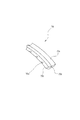
図4は、シール部材の一部を表した模式図である。図3も参照して、このシール部材70は、取付け部70aが、ハウジング部材縁部41cに形成されている溝部41eに取付けられ、摺接部70cが、内輪外側端面45bに接触し、内輪外側端面45bと縁部41cにより形成される開口部を塞いでいる。電動機10の運転時において、シール部材70は、ロータ保持部20と共に回転するので、摺接部70cが内輪外側端面45bに対して摺接しつつ、開口部をシールするように構成されている。
In FIG. 3, a portion of the
FIG. 4 is a schematic view showing a part of the seal member. Referring also to FIG. 3, this
摺接部70cには、摺接部70cの一部を切り欠くことで円周方向に沿って等間隔で連続的に凹部70dが形成されている。そして、シール部材70は、溝部41eに取付けられる際には、屈曲部70bで屈曲させた状態で取付けられる。このとき、摺接部70cは、その先端を外周方向に向けるようにして取付けられる。このようにすることで、シール部材70が伸直状態に戻ろうとする弾性力により、摺接部70cを内輪外側端面45bに押し付けてシール効果を高めている。
また、このシール部材70において、摺接部70c付近のみに主成分の合成ゴムの中に例えば鉄の微粉末を混入して成形している。これにより、摺接部70c付近のみをシール部材70の他の部分と比較して比重を大きくしている。
The sliding
Further, in the
また、図3を参照して、内輪45の軌道面端部には、玉軸受42の環状開口部を塞ぐように例えば合成ゴムを主成分とする円環状のシール部材71が取付けられている。このシール部材71は、内輪45の軌道面側に形成される溝部45cに取付けられ、摺接部71cが、外輪44の軌道面側端部44dに接触し、玉軸受42の環状開口部を塞いでいる。電動機10の運転時には、回転しない摺接部71cに対して、回転する外輪軌道面側端部44dとが摺接しつつ、環状開口部をシールするように構成されている。
Referring to FIG. 3, an
このシール部材71も上述のシール部材70と同様に摺接部71cには、摺接部71cの一部を切り欠くことで円周方向に沿って等間隔で連続的に凹部が形成されている。シール部材71は、玉軸受42に取付けられる際には、屈曲した状態で取付けられており、シール部材71が伸直状態に戻ろうとする弾性力により、摺接部71cを外輪軌道面側端部44dに押し付けてシール効果を高めている。
シール部材70とシール部材71と玉軸受42とハウジング部材41とにより形成される円環状の空間72には、例えばグリスが充填されており、外部に漏れないように保持されている。
Similarly to the
An
図5は、図1中、本発明の第一の実施形態に係る電動機10の一部分を示した円筒軸方向断面図である。ロータ保持部20の内周側に形成されている円環状の磁石取付部25には、円環状の磁石26が一体に固定されている。この磁石26は、外周は前記磁石取付部25の内径と略同じ直径で形成されており、複数の磁極が連続的に配置されている。ホール素子を含んだホールIC34は、ステータ保持部30に取付けられている取付板35に固定されている。そして、このホールIC34は、ロータ保持部20と一体に回転する前記円環状の磁石25の内周面とホールIC34とが常に一定の間隔をもって対向配置されるように固定されている。
FIG. 5 is a sectional view in the cylindrical axis direction showing a part of the
上記のように構成された本実施形態にかかる電動機10は、ロータR及びステータSが円筒状に構成されているので、上記従来例よりも軽量なものとすることができる。従って、本実施例のように、電動機10を車軸50に搭載した場合にも、バネ下重量の増加を抑制することができる。また、この電動機10は、減速機等を介さずロータRにより駆動輪60を直接的に駆動しているので、駆動効率が高いものとなる。
さらに、本実施形態では、電動機10は、ダンパー54とフレキシブル継手53とを介して車軸50に支持され、駆動輪60と前記ロータ保持部20はフレキシブル継手57で連結されている。従って、車両が走行して車軸が上下に振動した場合にも、電動機10は車軸50に対して上下動が可能であるので、車軸軸50の上下動を電動機10に伝達するのを抑え、電動機10ができるだけ車体に対して上下方向に振動するのを抑制することができる。これにより、電動機10が車軸50へ与える影響を少なくすることができるため、駆動輪60の路面に対する追従性が低下するのを抑制し、乗り心地性が悪化することを抑制できる。また、この電動機10において、車両を支えるための負荷荷重は、駆動輪60を支持している車軸50やサスペンション50dにより負担されており、電動機10には、前記負荷荷重は、全く作用しないように搭載されている。これにより、電動機10は、外部から作用する荷重を考慮する必要性が低くなるので、より軽量な構造設計とすることができる。
Since the rotor R and the stator S are configured in a cylindrical shape, the
Further, in the present embodiment, the
また、本実施形態では、シール部材70とシール部材71と玉軸受42とハウジング部材41とにより形成される円環状の空間72には、グリスが充填されているので、両シール部材70,71の摺接部70c,71cは、常にグリスにより潤滑される。これによって、摺接部70c,71cは、これらに接触している部材と摺動しても摩耗を抑制することができ、両シール部材70,71の寿命が向上する。これにより長期に渡って電動機内部への耐防塵・耐水性を維持することができる。また、摺接部70c,71cには、その一部を切り欠くことで円周方向に沿って等間隔で連続的に凹部が形成されているので、摺接部70c,71cとこれに接触している部材との接触面積が減少し、高速回転時でも摺接部70c,71cでの動摩擦力が大きくなることを抑制することができ、当該シール部材70,71の寿命を向上させることができる。よって、軸受寿命の向上および電動機内部への耐防塵・耐防水性を維持することができる。
In the present embodiment, the
さらに、シール部材70は、摺接部70cを外周方向に向けるように屈曲させて取付けられているので、電動機10の運転時に、シール部材70が高速回転した場合、摺接部70cは、遠心力により外周方向への力を受ける。すなわち、摺接部70cには、内輪外側端面45bから離反するように遠心力が作用する。それに加えて、摺接部70c付近は、主成分の合成ゴムの中に鉄の微粉末を混入して成形されており、摺接部70c付近のみ他の部分と比較して比重を大きくしているので、摺接部70cに作用する遠心力は、より高められ、内輪外側端面45bから離反する方向への力が高められる。これにより、ロータRの回転速度に応じて摺接部70cを広げさせることができる。よって、ロータRの回転速度に応じて摺接部70cでの接触面圧を変化させることができ、高速回転時でも当該摺接部70cでの動摩擦力の増加を抑えることができる。よって、軸受寿命の向上および電動機内部への耐防塵・耐防水性を維持することができる。
Further, since the
また、本実施形態では、ステータ保持部30にホールIC34を備え、ロータ保持部20に円環状磁石25を備えているので、電動機10の運転時にロータの回転数および回転位置を検出することができ、電動機10の運転制御が容易なものにできる。
Further, in the present embodiment, since the
また、本実施形態に係る軸受ユニット40は、その玉軸受42がロータR及びステータSの各軸方向両端部に取付けられている。また、その内輪45の内周面がステータS側の軸受取付面32に対し着脱可能に嵌合されるとともに、外輪44の外周面の一方側に構成された上記露出面44cがロータR側の軸受取付面22に対し着脱可能に嵌合され、かつ外輪外周面の他方側に嵌合されたハウジング部材41がロータR側のロータ保持部20に対し着脱可能に固定されている。これにより、玉軸受42を電動機10に対して着脱可能に取付けることができ、当該玉軸受42の点検時や異常発生時などに、電動機10を分解しなくても電動機10から玉軸受42のみを取付・取外しすることができる。
In the bearing
図6は、本発明の第二の実施形態に係る車両用電動機の一部分を示した円筒軸方向断面図である。本実施形態と第一の実施形態との主な相違点は、ロータ保持部20に電動機10の内部空間から外部空間への一方向のみに通気可能に構成されたリリーフ弁27を設けた点である。
このリリーフ弁27は、ロータ保持部20に形成された連通孔27eと、連通孔27e内で上記内部空間側に設けられた弁座27fと、連通孔27e内を移動可能に配置された栓部材としてのボール27cと、連通孔27eの内部に配置された付勢手段としてのスプリング27dと、前記スプリング27dを連通孔27eに留めるための円筒状部材27aとにより構成されている。
連通孔27eは、電動機10の内部空間と外部空間とを連通しており、その内径は、ボール27cが自在に移動可能な径に設定されている。そして、上記弁座27fはボール27cが密接可能なように半球状に形成されており、当該弁座27fにボール27cが密接したときに連通孔27eは閉塞状態とされ、またボール27cが弁座27fから離反したときに連通孔27eは開放状態とされるようになっている。また、このボール27cには、一端側が円筒状部材27aに当接したスプリング27dの他端側が当接されており、ボール27cがスプリング27dによって弁座27f側に付勢されており、スプリング27dの付勢力によってボール27cと弁座27fとの密接状態が維持されて連通孔27eは閉塞状態で保持されている。
FIG. 6 is a sectional view in the cylindrical axis direction showing a part of the vehicle electric motor according to the second embodiment of the present invention. The main difference between the present embodiment and the first embodiment is that the
The
The
このように構成されたリリーフ弁27では、電動機10の運転に伴う当該電動機10の内部の温度上昇によってその内部空間が熱せられ、その内部圧力が上昇した場合、ボール27cには、その内部圧力(空気圧)によってロータ保持部20外側方向へ押し上げられる力が作用する。そして、上記内部圧力がスプリング27dの付勢力以上に達したときには、ボール27cは、その押し上げられる力により弁座27fから離される。これによりリリーフ弁27は作動して、連通孔27eが閉塞状態から開放状態となり、電動機10の内部圧力を下げることができる。このとき、スプリング27dの自由長やバネ定数、連通孔27eや通気孔27bの内径等は、電動機10の内部圧力が最適な値に保持できるように設定されている。
In the
上記のように構成された本実施形態にかかる電動機10は、その運転に伴う温度上昇により電動機内部の圧力が高くなった場合にのみ開口するリリーフ弁27が設けられているので、電動機の外部からの粉塵や水分等の電動機内部への侵入を防ぎながら、電動機内部の異常な圧力上昇を抑えることができる。
また、上記の説明では、ロータ保持部20にリリーフ弁27を設けた構成について説明したが、ステータS側のステータ保持部30にリリーフ弁27を設ける構成でもよい。また、リリーフ弁27には、栓部材としてボール27cと、半球状に形成された弁座27fとを用いたが、三角柱形状の栓部材と、その栓部材に対して密着可能な弁座とを用いてもよい。
The
In the above description, the configuration in which the
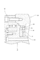
図7は、本発明の第三の実施形態に係る電動機10の一部分を示した円筒軸方向断面図である。本実施形態と第一および第二の実施形態との主な相違点は、ステータ保持部30の内周面に電動機10を冷却するためのウォータージャケット37を設けた点である。
このウォータージャケット37は、冷却水路37aが内部に形成されている。このウォータージャケット37は、ステータ保持部30の内周部に形成されたウォータージャケットの取付部38に、ウォータージャケット37の外周面が密着するように圧入されている。このとき、取付部38は、ウォータージャケット37が圧入された時にステータ保持部30内周面には段差が形成されないように形成されている。そして、冷却水路37aには冷却水が流され、ステータ保持部30を冷却するように構成されている。
上記のように構成された本実施形態にかかる電動機10は、高負荷で電動機が運転された場合でも、ウォータージャケット37によって、電動機の運転に伴う温度上昇を抑え、その温度上昇による電動機の破損等を防止することができる。
FIG. 7 is a cylindrical axial direction sectional view showing a part of the
The
Even when the
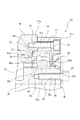
図8は、本発明の第四の実施形態である電動機の一部分を示した円筒軸方向断面図である。本実施形態と第一、第二及び第三の実施形態との相違点は、電動機10両端部に取付けられている軸受ユニット80の構成において、内輪の内周側にもハウジング部材を取付けた点である。
FIG. 8 is a sectional view in the cylindrical axis direction showing a part of the electric motor according to the fourth embodiment of the present invention. This embodiment and the first is different from the second and third embodiments, the configuration of the
図中本実施形態に示す軸受ユニット80は、第一のハウジング部材81と第二のハウジング部材82と玉軸受83とを備えている。玉軸受83は、転動体としてのボール84と、内周面に軌道面を有する回転輪としての外輪85と、外周面に軌道面を有する固定輪としての内輪86とを備えている。第一のハウジング部材81は円筒形状をしており、その内径は玉軸受83の外輪85の外周直径と略同じに設定され、また、その外径はロータ保持部20の外径よりやや小さく設定されている。第一のハウジング部材81には、第一のハウジング部材81をロータ保持部20に固定するためのボルト87を通す貫通孔81cが第一のハウジング部材81の同心円に等配して形成されている。第二のハウジング部材82も円筒形状をしており、その外径は玉軸受83の内輪86の内周直径と略同じに設定され、また、その内径はステータ保持部30の内径と略同じに設定されている。第二のハウジング部材82には、第二のハウジング部材82をステータ保持部30に固定するためのボルト89を通す貫通孔82cが第二のハウジング部材82の同心円に等配して形成されている。そして、後述するように、第二のハウジング部材82は玉軸受83の内径に圧入され、玉軸受83は第一のハウジング部材81の内径に圧入されて一体とされている。
A bearing
ロータ保持部20の端面には、外輪85の外周面が取付けられる環状の軸受取付面22と玉軸受83の軸方向の位置を規制するための軸受規制部23が形成されている。また、ロータ保持部20の端面には、ネジ部24が、貫通孔81cに一致するように形成されている。このネジ部24には、第一のハウジング部材81をロータ保持部20に固定するためのボルト87が取付けられている。ステータ保持部30の端面には、内輪45の内周面が取付けられる軸受取付面32が形成されている。また、ステータ保持部30の端面には、ネジ部39が、貫通孔82cに一致するように形成されている。このネジ部39には、第二のハウジング部材82をロータ保持部20に固定するためのボルト89が取付けられている。
On the end surface of the
また、上記軸受ユニット80では、外輪85の内側端面85aが第一のハウジング部材81の内側端面81aよりもロータ保持部20側へ突出して外輪85の外周面の一方側に露出面85cが形成されるように、第一のハウジング部材81は当該外周面の他方側に嵌合されている。同様に、また、内輪86の内側端面86aが第二のハウジング部材82の内側端面82aよりもステータ保持部30側へ突出して内輪86の内周面の一方側に露出面86cが形成されるように、第二のハウジング部材82は当該内周面の他方側に嵌合されている。
Further, in the bearing
上記軸受ユニット80を電動機10に装着する場合、露出面85cはロータ保持部20の軸受取付面22に挿嵌され、露出面86cは、ステータ保持部30の軸受取付面32に挿嵌される。このようにしてロータ保持部20とステータ保持部30の端部に玉軸受83が取付けられ、ステータ保持部30は、玉軸受83を介してロータ保持部20を同軸で回転自在に支持することができる。また、このとき、軸受取付面22と露出面85cとは、着脱可能に嵌合されている。同様に露出面86cと前記軸受取付面32とは着脱可能に嵌合されている。
そして、第一のハウジング部材81は、複数のボルト87によりロータ保持部20の端面に固定され、また、第二のハウジング部材82は、複数のボルト89によりステータ保持部30の端面に固定されている。
さらに、第一のハウジング部材81と第二のハウジング部材82とにより形成される環状開口部には、玉軸受83を保護するため、円環状のシール部材90が装着される。そして、このシール部材90の脱落を防止するために、円環状の止め板88が、第二のハウジング部材82をステータに固定しているボルト89により共締めされて固定されている。このようにして、軸受ユニット80は電動機10に取付けられている。
When the bearing
The
Further, an
上記のように構成された軸受ユニット80は、上記露出面85c及び86cが対応する軸受取付面22及び32に対して着脱可能に嵌合されているので、玉軸受83を電動機10に対して着脱可能に取付けることができる。これにより、上記実施形態と同様に、玉軸受83の点検時や異常発生時などに、電動機10を分解しなくても電動機10から玉軸受42のみを取付・取外しすることができる。また、本実施形態では、玉軸受83の開口部は、軸受ユニット80に取付けられる円環状のシール部材90でシールすることができるので、軸受ユニット40の耐防塵、耐水性が向上し、軸受寿命の低下を抑制することができる。
Bearings unit constructed as described above 80, since the exposed
本実施形態で示した軸受ユニット80では、内輪85の内径には第二のハウジング部材82が圧入されているが、内輪85の内径と第二のハウジング部材82とは、着脱可能に嵌合されていてもよい。第二のハウジング部材82は内輪85に取付けられ、それ自身は回転しないので特に強固に固定する必要がないからである。
In the bearing
上記説明した軸受ユニット40,80では、外輪の外周面のみにハウジング部材41を嵌合した場合と、内外輪の周面にハウジング部材81,82を嵌合した場合とを示したが、内輪の内周面にのみハウジング部材を嵌合した構成でもよい。
また、上記軸受ユニット40,80では、外輪にはロータRが取付けられ、内輪にはステータSが取付けられる構成となっていたが、当該軸受ユニットが取付けられる電動機の構成により、外輪にステータが取付けられ、内輪にロータが取付けられる構成でもよい。
In
Further, the upper
尚、上記説明した本発明に係る車両用電動機の実施形態は電気自動車に適用した場合であるが、タイヤ駆動の新交通システム、荷役システムなどへの適用や、タイヤの替わりに鉄輪を用いた軌道上を走行する路面電車、レールバスなどへも適用可能であることはいうまでもない。 Although the above-described embodiment of the vehicle motor according to the present invention is applied to an electric vehicle, it is applied to a tire-driven new traffic system, a cargo handling system, etc., or a track using an iron wheel instead of a tire. Needless to say, the present invention can be applied to a tram or a rail bus running on the road.
また、上記に説明した軸受ユニットでは、転がり軸受として玉軸受を用いたが、ころ軸受等の玉軸受以外の転がり軸受を用いてもよい。 Further, the bearings units described above, was used a ball bearing as the rolling bearing may be used rolling bearings other than ball bearings, such as roller bearings.
本発明の車両用電動機は、上記各実施形態に限定されるものではなく、電動機の構成や、車両への搭載方法、軸受ユニットの設置数、ハウジング部材の設置数や設置箇所等は、本発明の趣旨に基づいて適宜変更することができる。 Motor vehicle of the present invention is not limited to the above embodiment, the configuration and the electric motor, the method mounted on the vehicle, the number of installation of the bearing unit, the installation number and installation locations, etc. of the housing members, the It can change suitably based on the meaning of invention.
10 電動機
21 ロータ本体
22 軸受取付面
26 磁石
27 リリーフ弁
27e 連通孔
31 ステータ本体
32 軸受取付面
34 ホールIC
37 ウォータージャケット
40,80 軸受ユニット
41,81,82 ハウジング部材
42,83 玉軸受
43,84 ボール(転動体)
44,85 外輪
44c,85c,86c 露出面
45,86 内輪
60 駆動輪
70,71,90 シール部材
70c,71c 摺接部
70d 凹部
R ロータ
S ステータ
DESCRIPTION OF
37
44, 85
Claims (5)
内輪と、外輪と、これら内外輪間に転動自在に設けられた複数の転動体とを備えた転がり軸受を有し、前記ステータの軸方向両端部及び前記ロータの軸方向両端部に、前記内輪及び前記外輪の一方及び他方がそれぞれ取付けられ、前記ステータに対して前記ロータを回転自在に支持する軸受ユニットを備え、
前記軸受ユニットは、前記内輪の内周面及び前記外輪の外周面の少なくとも一方の周面に嵌合されるとともに、その軌道輪が取付けられている前記ステータ又は前記ロータに対し着脱可能に固定される円環状のハウジング部材を有し、前記軌道輪は、その周面において、その軸方向の一方側が前記ステータ又は前記ロータ側に形成された環状の取付面に対し着脱可能に取り付けられているとともに、他方側が前記ハウジング部材に嵌合されており、
前記軸受ユニットは、さらに、前記内外輪間に取付けられた第一のシール部材と、前記内外輪間の環状開口部を塞ぐように前記ハウジング部材に取付けられた第二のシール部材とを有し、前記両シール部材において被シール面に摺接する摺接部には、当該シール部材の主成分よりも比重の大きい微粉末が混入されていることを特徴とする車両用電動機。 A vehicular electric motor comprising a stator and a rotor, wherein a driving wheel of the vehicle is rotated by the rotor,
An inner ring, an outer ring and, have a rolling bearing that includes a plurality of rolling elements disposed rollably between these inner and outer rings, the axial ends of the axial end portion and the rotor of said stator, said One and the other of the inner ring and the outer ring are attached, respectively, and includes a bearing unit that rotatably supports the rotor with respect to the stator,
The bearing unit is fitted to at least one of the inner peripheral surface of the inner ring and the outer peripheral surface of the outer ring, and is detachably fixed to the stator or the rotor to which the race ring is attached. The bearing ring is detachably attached to the annular attachment surface formed on the stator or the rotor side on one side in the axial direction of the raceway ring . And the other side is fitted to the housing member ,
The bearing unit further includes a first seal member attached between the inner and outer rings and a second seal member attached to the housing member so as to close an annular opening between the inner and outer rings. An electric motor for a vehicle , wherein a fine powder having a specific gravity larger than that of a main component of the seal member is mixed in a sliding contact portion that is in sliding contact with a surface to be sealed in both the seal members .
内輪と、外輪と、これら内外輪間に転動自在に設けられた複数の転動体とを備えた転がり軸受を有し、前記内輪及び前記外輪が前記ステータの軸方向両端部及び前記ロータの軸方向両端部にそれぞれ取付けられ、前記ステータに対して前記ロータを回転自在に支持する軸受ユニットを備え、A rolling bearing having an inner ring, an outer ring, and a plurality of rolling elements provided between the inner and outer rings so as to be able to roll; the inner ring and the outer ring are axially opposite ends of the stator and a shaft of the rotor; A bearing unit that is attached to each of both ends in the direction, and rotatably supports the rotor with respect to the stator;
前記軸受ユニットは、前記内輪の内周面及び前記外輪の外周面の少なくとも一方の周面に嵌合されるとともに、その軌道輪が取付けられている前記ステータ又は前記ロータに対し着脱可能に固定される円環状のハウジング部材を有し、前記軌道輪は、その周面において、その軸方向の一方側が前記ステータ又は前記ロータ側に形成された環状の取付面に対し着脱可能に取り付けられているとともに、他方側が前記ハウジング部材に嵌合されており、The bearing unit is fitted to at least one of the inner peripheral surface of the inner ring and the outer peripheral surface of the outer ring, and is detachably fixed to the stator or the rotor to which the race ring is attached. And the bearing ring is detachably attached to an annular attachment surface formed on the stator or the rotor side on the circumferential surface of the raceway ring. The other side is fitted to the housing member,
前記軸受ユニットは、さらに、前記内外輪間に取付けられた第一のシール部材と、前記内外輪間の環状開口部を塞ぐように前記ハウジング部材に取付けられた第二のシール部材とを有し、前記第一及び第二のシール部材間には潤滑剤が充填され、The bearing unit further includes a first seal member attached between the inner and outer rings and a second seal member attached to the housing member so as to close an annular opening between the inner and outer rings. In addition, a lubricant is filled between the first and second sealing members,
前記両シール部材には、被シール面に摺接する摺接部が設けられているとともに、この摺接部には、前記被シール面に対する接触面積を減少させる凹部が形成され、Both the sealing members are provided with a sliding contact portion that is in sliding contact with the surface to be sealed, and a concave portion that reduces a contact area with respect to the surface to be sealed is formed in the sliding contact portion,
前記シール部材の摺接部には、当該シール部材の主成分よりも比重の大きい微粉末が混入されていることを特徴とする車両用電動機。A vehicular electric motor characterized in that a fine powder having a specific gravity larger than that of a main component of the seal member is mixed in the sliding contact portion of the seal member.
この連通孔を閉塞し、電動機の内部空間の圧力が所定値以上になると当該連通孔を開放するリリーフ弁とを備えることを特徴とする請求項1〜3のいずれか一項に記載の車両用電動機。 A communication hole that is formed on at least one side of the rotor and the stator and communicates an internal space and an external space of the motor;
4. The vehicle according to claim 1, further comprising a relief valve that closes the communication hole and opens the communication hole when the pressure in the internal space of the electric motor exceeds a predetermined value . Electric motor.
Priority Applications (1)
| Application Number | Priority Date | Filing Date | Title |
|---|---|---|---|
| JP2003391029A JP4423014B2 (en) | 2002-11-22 | 2003-11-20 | Electric motor for vehicle |
Applications Claiming Priority (2)
| Application Number | Priority Date | Filing Date | Title |
|---|---|---|---|
| JP2002339013 | 2002-11-22 | ||
| JP2003391029A JP4423014B2 (en) | 2002-11-22 | 2003-11-20 | Electric motor for vehicle |
Publications (2)
| Publication Number | Publication Date |
|---|---|
| JP2004245409A JP2004245409A (en) | 2004-09-02 |
| JP4423014B2 true JP4423014B2 (en) | 2010-03-03 |
Family
ID=33031663
Family Applications (1)
| Application Number | Title | Priority Date | Filing Date |
|---|---|---|---|
| JP2003391029A Expired - Lifetime JP4423014B2 (en) | 2002-11-22 | 2003-11-20 | Electric motor for vehicle |
Country Status (1)
| Country | Link |
|---|---|
| JP (1) | JP4423014B2 (en) |
Families Citing this family (5)
| Publication number | Priority date | Publication date | Assignee | Title |
|---|---|---|---|---|
| JP4694147B2 (en) * | 2004-05-26 | 2011-06-08 | トヨタ自動車株式会社 | Wheel support device |
| JP4986421B2 (en) * | 2005-07-11 | 2012-07-25 | 株式会社ブリヂストン | Shaft coupling and in-wheel motor system using the same |
| JP2009144739A (en) * | 2007-12-11 | 2009-07-02 | Jtekt Corp | Bearing device for vehicle |
| WO2013018394A1 (en) * | 2011-08-02 | 2013-02-07 | 日本精工株式会社 | Hub bearing, speed reduction mechanism, and in-wheel motor |
| DE102016109221B4 (en) * | 2016-05-19 | 2021-04-01 | Ujet S.A. | Wheel with drive unit for a vehicle, method for assembling a wheel and sealing device for sealing a bearing device of a wheel |
-
2003
- 2003-11-20 JP JP2003391029A patent/JP4423014B2/en not_active Expired - Lifetime
Also Published As
| Publication number | Publication date |
|---|---|
| JP2004245409A (en) | 2004-09-02 |
Similar Documents
| Publication | Publication Date | Title |
|---|---|---|
| CN101044035B (en) | Vehicle ground connection comprising a wheel and a suspension integrated therein | |
| CN109121405B (en) | Electric wheel of vehicle | |
| CN102958729B (en) | Motor-driven wheel hub including electric traction unit | |
| EP1636060B1 (en) | Suspension system for suspending a wheel having a motor therein | |
| JP2728648B2 (en) | Anti-friction bearing capable of generating electric energy | |
| JP5069975B2 (en) | In-wheel motor drive device | |
| US7530416B2 (en) | Motor-driven wheel driving apparatus | |
| US20080174190A1 (en) | Rotating electrical machine | |
| RU2136523C1 (en) | Drive set for electric rail vehicles | |
| JP4423014B2 (en) | Electric motor for vehicle | |
| JP2017057901A (en) | Motor drive unit for vehicle | |
| US10988147B2 (en) | Independent wheel drive device and vehicle | |
| CN100509446C (en) | Door type structure axle assembly especial for low chassis car | |
| JP2007191035A (en) | In-wheel motor system | |
| JP2007195320A (en) | In-wheel motor system | |
| JP4216000B2 (en) | Wheel shaft and bogie with variable gauge mechanism | |
| JP2007216928A (en) | In-wheel motor system | |
| JPH09119511A (en) | Gear device | |
| JP4380493B2 (en) | Electric wheel drive device | |
| CN207649914U (en) | A kind of three sections of shaft type rail vehicle axle head grounding device chambers | |
| JP2006117003A (en) | Electric wheel drive device | |
| JP2007190966A (en) | In-wheel motor system | |
| JP2002061660A (en) | Rolling bearing unit for wheel | |
| JP2008168822A (en) | In-wheel motor drive unit | |
| JP3702165B2 (en) | Independent wheel drive system using outer rotor type motor |
Legal Events
| Date | Code | Title | Description |
|---|---|---|---|
| A521 | Request for written amendment filed |
Free format text: JAPANESE INTERMEDIATE CODE: A523 Effective date: 20040622 |
|
| A621 | Written request for application examination |
Free format text: JAPANESE INTERMEDIATE CODE: A621 Effective date: 20061027 |
|
| A977 | Report on retrieval |
Free format text: JAPANESE INTERMEDIATE CODE: A971007 Effective date: 20090716 |
|
| A131 | Notification of reasons for refusal |
Free format text: JAPANESE INTERMEDIATE CODE: A131 Effective date: 20090804 |
|
| A521 | Request for written amendment filed |
Free format text: JAPANESE INTERMEDIATE CODE: A523 Effective date: 20091005 |
|
| A711 | Notification of change in applicant |
Free format text: JAPANESE INTERMEDIATE CODE: A711 Effective date: 20091019 |
|
| TRDD | Decision of grant or rejection written | ||
| A521 | Request for written amendment filed |
Free format text: JAPANESE INTERMEDIATE CODE: A821 Effective date: 20091019 |
|
| A01 | Written decision to grant a patent or to grant a registration (utility model) |
Free format text: JAPANESE INTERMEDIATE CODE: A01 Effective date: 20091201 |
|
| A01 | Written decision to grant a patent or to grant a registration (utility model) |
Free format text: JAPANESE INTERMEDIATE CODE: A01 |
|
| A61 | First payment of annual fees (during grant procedure) |
Free format text: JAPANESE INTERMEDIATE CODE: A61 Effective date: 20091207 |
|
| FPAY | Renewal fee payment (event date is renewal date of database) |
Free format text: PAYMENT UNTIL: 20121211 Year of fee payment: 3 |
|
| R150 | Certificate of patent or registration of utility model |
Ref document number: 4423014 Country of ref document: JP Free format text: JAPANESE INTERMEDIATE CODE: R150 Free format text: JAPANESE INTERMEDIATE CODE: R150 |
|
| FPAY | Renewal fee payment (event date is renewal date of database) |
Free format text: PAYMENT UNTIL: 20131211 Year of fee payment: 4 |
|
| R250 | Receipt of annual fees |
Free format text: JAPANESE INTERMEDIATE CODE: R250 |
|
| EXPY | Cancellation because of completion of term |