JP4422027B2 - Surgical stapling device - Google Patents
Surgical stapling device Download PDFInfo
- Publication number
- JP4422027B2 JP4422027B2 JP2004543410A JP2004543410A JP4422027B2 JP 4422027 B2 JP4422027 B2 JP 4422027B2 JP 2004543410 A JP2004543410 A JP 2004543410A JP 2004543410 A JP2004543410 A JP 2004543410A JP 4422027 B2 JP4422027 B2 JP 4422027B2
- Authority
- JP
- Japan
- Prior art keywords
- anvil
- assembly
- indicator
- stapling device
- screw
- Prior art date
- Legal status (The legal status is an assumption and is not a legal conclusion. Google has not performed a legal analysis and makes no representation as to the accuracy of the status listed.)
- Expired - Fee Related
Links
Images


Classifications
-
- A—HUMAN NECESSITIES
- A61—MEDICAL OR VETERINARY SCIENCE; HYGIENE
- A61B—DIAGNOSIS; SURGERY; IDENTIFICATION
- A61B17/00—Surgical instruments, devices or methods, e.g. tourniquets
- A61B17/068—Surgical staplers, e.g. containing multiple staples or clamps
-
- A—HUMAN NECESSITIES
- A61—MEDICAL OR VETERINARY SCIENCE; HYGIENE
- A61B—DIAGNOSIS; SURGERY; IDENTIFICATION
- A61B17/00—Surgical instruments, devices or methods, e.g. tourniquets
- A61B17/11—Surgical instruments, devices or methods, e.g. tourniquets for performing anastomosis; Buttons for anastomosis
- A61B17/115—Staplers for performing anastomosis in a single operation
- A61B17/1155—Circular staplers comprising a plurality of staples
-
- A—HUMAN NECESSITIES
- A61—MEDICAL OR VETERINARY SCIENCE; HYGIENE
- A61B—DIAGNOSIS; SURGERY; IDENTIFICATION
- A61B17/00—Surgical instruments, devices or methods, e.g. tourniquets
- A61B17/32—Surgical cutting instruments
- A61B17/3205—Excision instruments
- A61B17/32053—Punch like cutting instruments, e.g. using a cylindrical or oval knife
-
- A—HUMAN NECESSITIES
- A61—MEDICAL OR VETERINARY SCIENCE; HYGIENE
- A61B—DIAGNOSIS; SURGERY; IDENTIFICATION
- A61B17/00—Surgical instruments, devices or methods, e.g. tourniquets
- A61B2017/00367—Details of actuation of instruments, e.g. relations between pushing buttons, or the like, and activation of the tool, working tip, or the like
- A61B2017/00371—Multiple actuation, e.g. pushing of two buttons, or two working tips becoming operational
-
- A—HUMAN NECESSITIES
- A61—MEDICAL OR VETERINARY SCIENCE; HYGIENE
- A61B—DIAGNOSIS; SURGERY; IDENTIFICATION
- A61B17/00—Surgical instruments, devices or methods, e.g. tourniquets
- A61B17/068—Surgical staplers, e.g. containing multiple staples or clamps
- A61B17/072—Surgical staplers, e.g. containing multiple staples or clamps for applying a row of staples in a single action, e.g. the staples being applied simultaneously
- A61B2017/07214—Stapler heads
- A61B2017/07257—Stapler heads characterised by its anvil
-
- A—HUMAN NECESSITIES
- A61—MEDICAL OR VETERINARY SCIENCE; HYGIENE
- A61B—DIAGNOSIS; SURGERY; IDENTIFICATION
- A61B17/00—Surgical instruments, devices or methods, e.g. tourniquets
- A61B17/28—Surgical forceps
- A61B17/29—Forceps for use in minimally invasive surgery
- A61B2017/2901—Details of shaft
- A61B2017/2905—Details of shaft flexible
-
- A—HUMAN NECESSITIES
- A61—MEDICAL OR VETERINARY SCIENCE; HYGIENE
- A61B—DIAGNOSIS; SURGERY; IDENTIFICATION
- A61B90/00—Instruments, implements or accessories specially adapted for surgery or diagnosis and not covered by any of the groups A61B1/00 - A61B50/00, e.g. for luxation treatment or for protecting wound edges
- A61B90/08—Accessories or related features not otherwise provided for
- A61B2090/0807—Indication means
- A61B2090/0811—Indication means for the position of a particular part of an instrument with respect to the rest of the instrument, e.g. position of the anvil of a stapling instrument
-
- A—HUMAN NECESSITIES
- A61—MEDICAL OR VETERINARY SCIENCE; HYGIENE
- A61B—DIAGNOSIS; SURGERY; IDENTIFICATION
- A61B90/00—Instruments, implements or accessories specially adapted for surgery or diagnosis and not covered by any of the groups A61B1/00 - A61B50/00, e.g. for luxation treatment or for protecting wound edges
- A61B90/36—Image-producing devices or illumination devices not otherwise provided for
- A61B90/361—Image-producing devices, e.g. surgical cameras
- A61B2090/3616—Magnifying glass
Description
本出願は、2002年10月4日に出願された米国仮特許出願番号第60/416,055号から優先権を主張し、この出願の全体は、引用することにより本明細書に援用する。 This application claims priority from US Provisional Patent Application No. 60 / 416,055, filed Oct. 4, 2002, which is hereby incorporated by reference in its entirety.
(背景)
1.技術分野
本発明の開示事項は、一般に、外科手術用のステープルを人体組織に適用するための外科手術用ステープリングデバイスに関する。詳細には、本発明の開示事項は、中空組織器官の円形吻合実施するのに適する外科手術用ステープリングデバイスに関する。
(background)
1. TECHNICAL FIELD The present disclosure generally relates to a surgical stapling device for applying surgical staples to human tissue. In particular, the present disclosure relates to a surgical stapling device suitable for performing circular anastomoses of hollow tissue organs.
2.背景技術
吻合は、別個の中空組織部分を外科手術で結合することである。一般に、吻合手順は、中空組織の罹患または欠陥部分を除去して、残存端部部分を結合する外科手術に従う。所望の吻合手順に応じて、端部部分は、円形、端部−側部または側部−側部器官の再構築法により結合される。
2. BACKGROUND ART An anastomosis is the surgical joining of separate hollow tissue sections. In general, the anastomosis procedure follows a surgical procedure that removes the diseased or defective portion of the hollow tissue and joins the remaining end portions. Depending on the desired anastomosis procedure, the end portions are joined by a circular, end-side or side-side organ reconstruction method.
円形吻合手順では、器官部分の2つの端部はステープリング機器により結合され、ステープリング機器は、ステープルの円形配列が各器官部分の端部部分を貫通するように駆動し、同時に、駆動されるステープルの円形配列の内側にある組織を除芯して、環状通路を解放する。中空組織の円形吻合を行なうための器具の実施例は、米国特許第6,053,390号、第5,588,579号、第5,119,983号、第5,005,749号、第4,646,745号、第4,576,167号、および第4,473,077号に記載されており、これらの特許は、引用することにより全体を本明細書に援用する。一般に、こうした器具は、近位端にハンドル部分を有する長形シャフトを備え、ハンドル部分は、遠位端に配置された器具およびステープル保持構成部品を作動させる。アンビルロッドおよび取り付けられたアンビルヘッドを備えるアンビル組立体は、ステープル保持構成部品に隣接する遠位端に実装される。ステープリングされる器官の組織の対向端部部分は、アンビルヘッドとステープル保持構成部品との間に圧締される。圧締された組織は、1個または複数のステープルをステープル保持構成部品から駆動して、ステープルの両端が組織を通過し、アンビルヘッドによって変形するようにしてステープリングされる。 In a circular anastomosis procedure, the two ends of the organ parts are joined by a stapling instrument that drives the circular array of staples through the end parts of each organ part and is driven simultaneously. The tissue inside the circular array of staples is decentered to release the annular passage. Examples of instruments for performing circular anastomoses of hollow tissue are described in US Pat. Nos. 6,053,390, 5,588,579, 5,119,983, 5,005,749, 4,646,745, 4,576,167, and 4,473,077, which are hereby incorporated by reference in their entirety. In general, such instruments comprise an elongate shaft having a handle portion at a proximal end, which actuates an instrument and staple holding component disposed at the distal end. An anvil assembly comprising an anvil rod and an attached anvil head is mounted at the distal end adjacent to the staple holding component. Opposite end portions of the tissue of the organ to be stapled are clamped between the anvil head and the staple holding component. The pressed tissue is stapled by driving one or more staples from the staple holding component so that both ends of the staples pass through the tissue and are deformed by the anvil head.
使用時、ステープル保持構成部品およびアンビル組立体は、結合される器官の対向部分内に配置され、執刀医の目には見えない。一般に、インディケータは、執刀医の目に見えるステープリングデバイス上に設けられるため、アンビル組立体およびステープル保持部分が十分に接近し、デバイスが発射可能位置になったことを確認できる。従来のインディケータは、デバイスが接近すると執刀医の目に見える位置に移動される標示を備える。こうした標示は、見えにくい場合がある。 In use, the staple holding component and the anvil assembly are placed in opposite portions of the organ to be joined and are not visible to the surgeon. In general, the indicator is provided on the stapling device visible to the surgeon so that the anvil assembly and staple holding portion are sufficiently close to confirm that the device is in a fireable position. Conventional indicators comprise an indicator that is moved to a position visible to the surgeon as the device approaches. Such signs may be difficult to see.
したがって、執刀医が容易に見ることが可能な標示を顕著に標示する接近/発射可能インディケータを備えるステープリングデバイスに対する必要性が存在する。 Thus, there is a need for a stapling device with an approachable / fireable indicator that prominently displays an indication that can be easily viewed by the surgeon.
発明の開示
本発明の開示事項により、外科手術用ステープリングデバイスは、好ましくは円形吻合を行なうために開示する。外科手術用ステープリングデバイスは、ハンドル部分または組立体、本体部分、並びにアンビル組立体およびシェル組立体を備えるヘッド部分を備える。ハンドル部分は、アンビルおよびシェル組立体を接近させるための回転可能な接近ノブと、シェル組立体内に配置されたステープルを放出するための発射機構を作動させるための発射トリガとを備え得る。発射トリガは、好ましくは、発射機構を作動させるために設けられた2バーリンケージの1個のリンクを形成する。2バーリンケージは、デバイスを発射するのに要する発射力を減少させるという改善された機械的利益をデバイスに提供する。
SUMMARY OF THE INVENTION In accordance with the present disclosure, a surgical stapling device is preferably disclosed for performing a circular anastomosis. The surgical stapling device includes a handle portion or assembly, a body portion, and a head portion that includes an anvil assembly and a shell assembly. The handle portion, Ru obtained comprises a rotatable approximation knob for approximating the anvil and shell assemblies and a firing trigger for actuating a firing mechanism for releasing the staples disposed in the body shell assembly. The firing trigger preferably forms a single link of two bar linkages provided to actuate the firing mechanism. The two-bar linkage provides the device with improved mechanical benefits of reducing the firing force required to fire the device.
ヘッド部分はアンビル組立体を備え、アンビル組立体は、デバイスが発射されて非接近状態になると自動的に傾斜する傾斜可能なアンビルを備える。傾斜可能なアンビルは、減少したアンビルプロファイルを提供し、吻合手順が実施された後、デバイスを取り出す時の外傷を減少させる。 The head portion includes an anvil assembly that includes a tiltable anvil that tilts automatically when the device is fired and in an inaccessible state. The tiltable anvil provides a reduced anvil profile and reduces trauma when the device is removed after the anastomosis procedure has been performed.
外科手術用ステープリングデバイスは、デバイスが接近するまで、発射トリガの作動を防止する発射ロックアウト機構も備える。好ましい一実施態様では、発射ロックアウト機構は、ハンドル組立体内に移動可能に配置されたトリガロックおよびロックアウト部材を備える。ロックアウト部材は、デバイスが接近するまで、トリガロックがロック位置からアンロック位置に移動するのを防止する。 The surgical stapling device also includes a firing lockout mechanism that prevents actuation of the firing trigger until the device is approached. In a preferred embodiment, the firing lockout mechanism comprises a trigger lock and lockout member that is movably disposed within the handle assembly. The lockout member prevents the trigger lock from moving from the locked position to the unlocked position until the device is approached.
外科手術用ステープリングデバイスは、触知式表示機構も備える。好ましい一実施態様では、触知式表示機構は、アンビルヘッドが、傾斜可能な十分な距離だけ非接近状態になり、したがって、デバイスを患者から取り外すことが可能であることを執刀医に認識させる。 The surgical stapling device also includes a tactile display mechanism. In one preferred embodiment, the tactile display mechanism allows the surgeon to recognize that the anvil head is out of proximity for a sufficient distance that can be tilted, thus allowing the device to be removed from the patient.
もう1つの好ましい実施態様では、ステープリングデバイスは、好ましくはデバイスのハンドル組立体の上面上に延在する球根状インディケータを備える。インディケータは、デバイスが接近して発射可能位置にあることを執刀医に認識させるための標示を備える。好ましくは、インディケータは、標示を顕著に表示するための拡大材料から形成されたカバーを備える。ここに開示するインディケータは、器具の上面および側面の両方から、執刀医に対する改善された可視化を提供する。 In another preferred embodiment, the stapling device preferably comprises a bulbous indicator that extends over the top surface of the device handle assembly. The indicator is provided with an indication to allow the surgeon to recognize that the device is close and in a fireable position. Preferably, the indicator comprises a cover formed from a magnifying material for prominently displaying the indication. The indicator disclosed herein provides improved visualization to the surgeon from both the top and side of the instrument.
もう1つの好ましい実施態様では、ステープリングデバイスのアンビル組立体は、アンビルヘッド上に配置されたリテーナクリップを備える。リテーナクリップは、好ましくは、少なくとも1個の弾性アームを備え、この弾性アームは、その非付勢位置で切断リングに係合し、切断リングが、ステープリングデバイスの非接近時にナイフブレードに付着するのを防止するように配置される。好ましい実施態様では、リテーナクリップは1対の弾性アームを備え、アンビル組立体内のアンビルポスト内にある横断スロット内に配置される。切断リングは、アンビルポストの周囲に配置され、弾性アームを横断スロット内に圧迫する。切断リングは、デバイスが発射されて、リテーナクリップの弾性アームが外側に、切断リングの運動を遮断する位置まで屈曲することが可能になると、アンビルポストの周囲で移動可能である。 In another preferred embodiment, the anvil assembly of the stapling device comprises a retainer clip disposed on the anvil head. The retainer clip preferably comprises at least one elastic arm that engages the cutting ring in its non-biased position and the cutting ring adheres to the knife blade when the stapling device is not approaching. It is arranged to prevent this. In a preferred embodiment, the retainer clip comprises a pair of resilient arms and is disposed in a transverse slot in the anvil post within the anvil assembly. A cutting ring is placed around the anvil post and presses the resilient arm into the transverse slot. The cutting ring is movable around the anvil post when the device is fired and the elastic arms of the retainer clip can be bent outward to a position that blocks the movement of the cutting ring.
(好ましい実施態様の詳細な説明)
ここに開示する外科手術用ステープリングデバイスの好ましい実施態様について、図面に関して詳細に説明し、図中、類似の参照符号は、いくつかの図面の各々で同一または対応する要素を指示する。
Detailed Description of Preferred Embodiments
Preferred embodiments of the surgical stapling device disclosed herein will be described in detail with reference to the drawings, wherein like reference numerals designate identical or corresponding elements in each of the several views.
本明細書の全体を通して、「近位」という用語は、操作者に最も近い器具の部分を指示し、「遠位」という用語は、操作者から最も離れた器具の部分を指示する。 Throughout this specification, the term “proximal” refers to the portion of the instrument that is closest to the operator, and the term “distal” refers to the portion of the instrument that is furthest away from the operator.
図1および図2は、ここに開示され、全体として参照符号10で示される外科手術用ステープリングデバイスの好ましい一実施態様である。簡潔に述べるなら、外科手術用ステープリングデバイス10は、近位のハンドル組立体12と、曲線状の長形外側管14aを備える長形の中心本体部分14と、遠位のヘッド部分16とを備える。別法によると、外科手術手順によっては、たとえば痔核の治療では、実質的に直線、好ましくは短い中心本体部分を有することが望ましい。本体部分14およびヘッド部分16の長さ、形状および/または直径も、特定の外科手順に適合するように変更することができる。
1 and 2 are one preferred embodiment of a surgical stapling device disclosed herein and indicated generally by the reference numeral 10. Briefly, the surgical stapling device 10 includes a
ハンドル組立体12は、固定ハンドル18と、発射トリガ20と、回転可能な接近ノブ22と、インディケータ24とを備える。固定ハンドル18は、好ましくは熱可塑性ハンドル部分18aおよび18b(図3)、たとえばポリカーボネートから形成し、これらは共に、ハンドル組立体12の内部構成部品のための筐体を画定する。ハンドル部分18aおよび18bは、好ましくは、超音波溶接により互いに固定する。別法によると、その他の公知の固定技術を使用することができ、たとえばスクリュー、接着剤、スナップ嵌合コネクタなどが挙げられる。ハンドル部分12の内部の構成部品について、以下で詳細に説明する。好ましくは、クッション状および/または弾性の滑り止め部分、たとえばグリップ(図示しない)は、発射トリガ20のハンドル部分18aおよび18bに固締されるか、またはこれらの一部として含まれる。滑り止めグリップは、オーバモルド手順を使用してハンドル部分18aおよび18b並びに発射トリガ20上に形成され、ネオプレンまたはゴムから形成され得る。別法によると、その他の適切な材料、たとえばエラストマー材料、および結合技術を使用することができる。枢動可能に実装されたトリガロック26はハンドル組立体12に固締され、ステープリングデバイス10の偶発的な発射を防止するように手動で配置される。インディケータ24は固定ハンドル18上に配置され、デバイスが接近し、発射可能であるかどうかを執刀医に認識させるための標示、たとえばカラーコード、英字ラベルなどを備える。インディケータ24は、ハンドル部分18aおよび18bの上面から外側に延在する球根状または凸状を有し、執刀医がステープリングデバイスの上面および側面から容易に見ることができる。
The
ヘッド部分16は、アンビル組立体30およびシェル組立体31を備える。これらの組立体の各々について、以下で詳細に説明する。特記しない限り、外科手術用デバイス10の構成部品は、一般に、ポリカーボネートを含む熱可塑性樹脂、およびステンレス鋼およびアルミニウムを含む金属から形成される。特定の構成部品を形成するために選択される特定の材料は、特定構成部品の強度要件によって決まる。たとえば、アンビルは、ステンレス鋼などの金属から形成することが好ましく、固定ハンドルは、ポリカーボネートなどの熱可塑性樹脂から形成することが好ましい。別法によると、上記に列挙しないその他の金属で、殺菌手順に耐えることが可能な金属を使用して、ステープリングデバイス10の構成部品を形成することができるが、材料は、外科手術用途に適し、特定構成部品の強度要件に適合することが条件である。
The
図3〜図5は、ハンドル組立体12の内部の構成部品を示す。内部の構成部品としては、接近および発射機構の近位の構成部品、発射ロックアウト機構、およびインディケータ駆動機構が挙げられる。図6および図7は、長形本体部分14の内部の構成部品を示す。これらの構成部品としては、接近および発射機構の遠位の構成部品が挙げられる。これらの機構の各々について、以下で詳細に説明する。
3 to 5 show the internal components of the
(接近機構)
図3〜図8を参照すると、接近機構は、接近ノブ22、駆動スクリュー32、回転可能スリーブ33、それぞれ第1および第2スクリューの延在部分34および36(図6)、およびアンビルリテーナ38を備える。回転可能スリーブ33は、実質的に円筒状の中空本体部分40と、実質的に円筒状のカラー42とを備え、これらは共に中心ボア33aを画定する。カラー42には、その周囲に環状の溝44が形成され、この溝は、ハンドル部分18aおよび18bの内壁上に形成された内側延在フランジ46を収容する寸法である。溝44とフランジ46との間の係合は、スリーブ33をハンドル18内に軸方向に固定し、しかも固定ハンドル18に関連してスリーブ33の回転を可能にする。回転可能スリーブ33の本体部分40の近位端は、固定ハンドル18の近位端にある開口部18bを通って延在する。正反対に対向する1対の長形リブ48は、本体部分40の外面上に配置されるか、または形成される。接近ノブ22は1対の内側スロット49aを備え、これらのスロットは、スリーブ33のリブ48を収容して、スリーブ33をノブ22に回転可能に固定するように配置され、その結果、ノブ22の回転により、スリーブ33が同時に回転する。
(Access mechanism)
With reference to FIGS. 3-8, the access mechanism includes an
スクリュー32の近位の半分は、螺旋状チャネル50を含み、回転可能スリーブ33の中心ボア33a内に摺動可能に配置される寸法に作られる。スクリュー32の遠位端は、スクリュー32の外面と、プッシャリンク74の内面との間に液密シールを提供するためのシール部材37(図3)を収容する寸法の環状凹部35を備える。ピン52(図3)は、スリーブ33の円筒状カラー42を通って螺旋状のチャネル50内に半径方向に延在する。スリーブ33は、固定ハンドル18に対して軸方向に固定されるため、スクリュー32の周囲におけるスリーブ33の回転により、ピン52は、スクリュー32のチャネル50に沿って移動し、スクリュー32を固定ハンドル18内において軸方向に移動させる。
The proximal half of the
図6〜図8を参照すると、スクリュー32の遠位端は横断スロット54を備える。上部および底部のスクリュー延在部分34および36(図6)の各々は、近位に位置する可撓性の平坦なバンド部分58と、遠位に位置する平坦なバンド部分60とを備える。別法によると、スクリューの延在部分34および36は、バンド構成以外の構成を有することができる。たとえば、スクリュー延在部分34および36は、断面が半円形および円形である。上部および下部スクリュー延在部分34および36の可撓性は、スクリュー延在部分34および36が曲線状の長形本体部分14を通って移動することを可能にする。各々のバンド部分58の近位端は孔62を備え、この孔は、スクリュー延在部分34および36の近位端をスクリュー32の横断スロット54内に固定するためのピン64を収容する寸法である。別法によると、その他の固締技術を使用して、各々のバンド部分58をスクリュー32に固定することができ、たとえば溶接、クリンプ加工などがある。各々のスクリュー延在部分34および36の遠位に位置するバンド部分は、アンビルリテーナ38(図7)の近位端内に形成された横断スロット66内に収容され、アンビルリテーナ38をスクリュー延在部分34および36の遠位端に固締する寸法に作られる。好ましくは、アンビルリテーナ38およびバンド部分60の近位端を通って延在する1対のピンは、スクリュー延在部分34および36をアンビルリテーナ38に固定するために使用される。別法によると、バンド部分60は、スロット66内に蝋付けもしくは溶接することができるか、またはその他の固締技術を使用して、スクリュー延在部分34および36のバンド部分60をアンビルリテーナ38、たとえばスクリュー、クリンプなどに固定する。アンビルリテーナ38は、以下で詳細に説明するように、アンビル組立体に係合するように構成された環状突出部177(図7)を備える。別法によると、突出部177は環状である必要はなく、様々な取付け構造、たとえば凹部、溝などを含む。
With reference to FIGS. 6-8, the distal end of
再び図3〜図7を参照すると、接近ノブ22を手動で回転させる場合、回転可能スリーブ33は、スクリュー32の近位端周囲で回転し、ピン52をスクリュー32の螺旋状チャネル50に沿って移動させる。スリーブ33は固定ハンドル18に軸方向に固定されるので、ピン52がチャネル50を通って移動すると、スクリュー32が前進し、固定ハンドル18内に後退する。その結果、スクリュー32の遠位端に固締される上部および底部スクリュー延在部分34および36と、スクリュー延在部分34および36の遠位端に固締されるアンビルリテーナ38とは、長形本体部分14内で軸方向に移動する。アンビル組立体30は、アンビルリテーナ38の遠位端に固定されるので、接近ノブ22の回転により、アンビル組立体30は、シェル組立体31に関連して離間位置と接近位置とので移動する。
Referring again to FIGS. 3-7, when manually rotating the
(発射機構)
図3〜図6および図9を参照すると、発射機構は、発射トリガ20と、発射リンク72と、長形のプッシャリンク74(図6)とを備える。発射トリガ20は、本体部分76およびトリガカバー80を備える。好ましくはネオプレンまたはゴムから形成されたクッション状把持表面(図示しない)は、トリガカバー80上に設けられる。クッション状把持表面は、滑り止めのクッション状表面を提供して、デバイス10の作動が執刀医にとってさらに快適になるようにする。トリガ20の本体部分76の遠位端は、枢動部材84により、結合部材86に枢動可能に接続される。結合部材86は、プッシャリンク74の近位端に固定され、プッシャリンク74と一体に、またはプッシャリンク74に固締された別個の要素として形成される。発射リンク72は、枢動部材87によりトリガ20の本体部分76に枢動可能に固定された遠位端と、枢動部材79により、固定ハンドル18の固定ハンドル半体部分18aおよび18bとの間に形成された垂直スロット82内に枢動可能に固定された第2端部とを備える。枢動部材79は、スロット82内で垂直に自由に移動する。ばね82a(図9)は、ハンドル18内に支持されて、枢動部材79をスロット82の底部方向に下方に圧迫する。トリガ20の本体部分76は、当接部分89および当接部分91を含む1対の当接部分をさらに備え、これらの当接部分は、以下に詳細に説明するようにトリガロック26の遠位端26a(図4)に係合するように配置され、デバイス10が接近する前にトリガ20が作動するのを防止する。
(Launch mechanism)
With reference to FIGS. 3-6 and 9, the firing mechanism includes a firing
長形プッシャリンク74の近位端に支持される結合部材86は、フランジ104(図6)を備える。ばね106は、外側管14aの近位端とフランジ104(図4)との間に配置され、プッシャリンクを近位に、後退した非発射位置に付勢する。1対のウィング108は、結合部材86から半径方向外側に延在する。ウィング108は、固定ハンドル18の内壁に沿って形成されたチャネル111(図3)に沿って摺動し、デバイス10の発射時に、プッシャリンク74の適切な整列を固定ハンドル18内で維持する寸法に作られる。
A
図6を参照すると、プッシャリンク74の遠位端は、プッシャバック186の近位端内に形成された部材220と錠止係合する寸法である。プッシャバック186はシェル組立体31の一部を形成しており、以下で詳細に説明する。プッシャリンク74は、好ましくは、可撓性プラスチック材料から形成し、プッシャリンクが、本体14を通って移動する時に、さらに容易に屈曲することを可能にする複数のノッチ187を備える。プッシャリンク74は、接近機構を摺動可能に収容するための中空チャネル76を画定する。プッシャリンク74に形成された平坦な表面つまりカットアウト74aは、並列アラインメントで配置されたスクリュー延在部分34および36を摺動可能に支持する。スペーサ77は、カットアウト74aに隣接する外側管14a内に配置されて、スクリュー延在部分34および36およびプッシャリンク74に対して追加の支持を提供し、各々の構成部品が、作動時に座屈するのを防止する。環状チャネル74bは、プッシャリンク74の周囲に形成されて、Oリングシール74cを収容する。プッシャリンク74は本体部分14内に摺動可能に配置され、その結果、Oリング74cは、プッシャリンク74と外側管14aの内壁との間の空間をシールする。デバイスの発射機構の作動について、以下で詳細に説明する。
Referring to FIG. 6, the distal end of
再び図3〜図6および図9を参照すると、発射トリガ20が作動すると、つまり枢動部材84の周囲で枢動すると、発射リンク72は、近位に移動し、枢動部材79がスクリューストップ306(図3)上に形成された当接部分の表面307(図25A〜D)に係合する。スクリューストップ306は、以下で詳細に説明するようにスクリュー32に軸方向に固定される。その後、発射トリガ20は遠位に押されて、プッシャリンク74をばね106の付勢に対抗して遠位に前進させる。プッシャリンク74の遠位端はプッシャバック186に接続され、発射トリガ20の作動により、プッシャバック186はシェル組立体31内で前進し、以下で説明するようにステープルをシェル組立体31から押し出すことができる。
Referring again to FIGS. 3-6 and 9, when the firing
(アンビル組立体)
図10〜図21を参照すると、アンビル組立体30は、アンビルヘッド組立体120と、アンビル中心ロッド組立体152とを含む。アンビルヘッド組立体120は、ポスト122と、アンビルヘッド124と、バックアッププレート126と、切断リング128と、保持クリップ127と、アンビル129とを含む。ポスト122は、アンビルヘッド124内のボアを通して中心に配置される。別法によると、ポスト122は、アンビルヘッド124と一体成形される。アンビル129は、外側環状凹部136内のアンビルヘッド124上に支持され、ステープルを収容して変形させるための複数のポケット140を備える。少なくとも1個のタブ129aは、アンビル129から半径方向外側に延在し、アンビルヘッド124内に形成されたカットアウト124a内に収容される寸法に作られる。タブ129aおよびカットアウト124aは、アンビル129を環状凹部136内でアラインする機能を果たす。バックアッププレート126は中心開口部126bを備え、この開口部は、アンビルヘッド124の内側凹部134内のポスト122周囲であって、ポスト122と環状凹部136との間に配置される。バックアッププレート126は、隆起したプラットフォーム126aを含む。切断リング128は、プラットフォーム126aと実質的に同じ構成の開口部128aを含む。開口部128aは、切断リング128aをバックアップリング126上に回転可能に固定するために、プラットフォーム126aの周囲に配置される。好ましくは、切断リング128はポリエチレンから形成され、たとえば接着剤を使用してバックアッププレート126に固定して取り付けられる。バックアップリング126は、好ましくは金属から形成し、切断リング128を支持して組織の切断を強化する。別法によると、構造のその他の材料は、プレート126およびリング128を構成するために使用される。切断リング128およびバックアッププレート126は、ポスト122周囲に摺動可能に実装される。バックアッププレート126は、以下で詳細に説明する1対の内側に延在するタブ150を備える。切断リング128はタブ128bを備え、このタブは、アンビルヘッド124内に形成されたカットアウト124b内に収容され、バックアップリング126および切断リング128をアンビルヘッド124内で適切にアラインする。
(Anvil assembly)
With reference to FIGS. 10-21, the
アンビル中心ロッド組立体152は、アンビル中心ロッド154と、プランジャ156と、プランジャばね158とを備える。中心ロッド154の第1端部は、中心ロッド154の中心の長手方向軸から偏位する横断方向貫通ボア160を含む。アンビルヘッド組立体120のポスト122は、横断方向貫通ボア162も含む。枢動部材164は、ポスト122を中心ロッド154に枢動可能に固定され、アンビルヘッド組立体120は、アンビル中心ロッド組立体152に枢動可能に実装される。プランジャ156は、中心ロッド154の第1端部に形成されたボア154b(図16)内に摺動可能に配置される。プランジャ156は係合フィンガ168を備え、この係合フィンガは、アンビルヘッド組立体120の枢軸から偏位して、プランジャばね158によりポスト122の基部122aと係合するように付勢され、アンビルヘッド組立体120を中心ロッド154に対してある角度で枢着位置に圧迫する。好ましい非傾斜位置では、バックアッププレート126上に形成されたタブ150は、中心ロッド154の上面154a(図20)と係合し、アンビルヘッド組立体120が枢動部材164の周囲で枢動するのを防止する。デバイス10が発射されると、バックアッププレート126および切断リング128は、以下でさらに詳細に説明するように、ナイフ188(図6)によりポスト122(図21)周囲のアンビルヘッド124のアンビル凹部134内にさらに深く移動し、タブ150を移動させて中心ロッド154の上面154aから離脱させ、プランジャ156が、アンビルヘッド組立体120を枢動部材164の周囲で枢動させることを可能にする。
The anvil
リテーナクリップ127は、ポスト122内に形成された横断スロット122c内に配置され、1対の外側に付勢された可撓性アーム127aおよび127bを備える。アーム127bは、枢動ピン164(図17)を収容する寸法に作られる。デバイス10を発射する前に、アーム127aおよび127bは、バックアッププレート126(図17)により内側に変形する。デバイス10が発射し、バックアッププレート126が、ナイフ188によりアンビルヘッド124内にさらに深く押し入れられた後、可撓性アーム127aおよび127bは、外側にバックアッププレート126の前面の位置に跳ねる。この位置では、アーム127aおよび127bは、切断リング128およびバックアッププレート126が、アンビル組立体30が非接近状態にある時に、ナイフに付着するのを防止する。リテーナクリップは、アンビルヘッドポストおよびアンビル中心ロッドが一体成形されている非枢動アンビル組立体と共に使用される。
The
中心ロッド154の第2端部は、複数の屈曲可能アーム155aにより画定されるボア170を含む。ボア170は、取り外し可能なトロカール157を収容する寸法に作られる。少なくとも1個の屈曲可能アーム155、および好ましくは複数、たとえば3個の屈曲可能アーム155は開口部155aを備え、この開口部は、取り外し可能なトロカール157上に形成された突出部157dを収容して、トロカール157を中心ロッド154(図13)に解除自在に固定する寸法に作られる。各々の可撓性アーム155の遠位端は、以下で詳細に説明するように、アンビルリテーナ38に解除自在に係合する寸法に作られた内側肩状部155b(図10)を備える。複数のスプライン181は、中心ロッド154の周囲に形成され、シェル組立体31の溝196a(図6)内に収容されて、アンビルおよびシェル組立体の接近時に、シェル組立体31内でアンビル組立体30とアラインする寸法に作られる。中心ロッド154は、執刀医が捕捉器具を使ってアンビル組立体30を把持するのを容易にする環状凹部部分183も備える。
The second end of the
図12および図13を参照すると、取り外し可能なトロカール157は、トロカール先端157aと、本体部分157bと、片持ち梁アーム157cとを備える。突出部157dは、片持ち梁アーム157cの自由端上に配置される。アーム157cは、図13に矢印「A」で示す方向の下方に、つまり半径方向内側に屈曲可能であり、本体部分157bを中心ロッド154のボア170内に容易に挿入することができる。スプライン157eまたはその他は、好ましくは、本体部分157b上に設けられ、トロカール157をボア170内に適切にアラインする。アーム157cは、突出部157dを外側に付勢し、その結果、突出部157dが中心ロッド154内の開口部155aの下を通過する時、突出部157dは外側に開口部155a内にスナップ嵌合し、取り外し可能なトロカール157を中心ロッド154に解除自在に固定する。タブ157fはアーム157c上に配置され、押下げアーム157cおよび突出部157dに係合して、突出部157dをアーム155の開口部155aから取り出して、トロカール157を中心ロッド154から容易に取り出せるようにする。トロカール先端157aは貫通ボア157gを含み、この貫通ボアは、縫合糸(図示しない)を収容し、トロカール157および/またはアンビル組立体30を容易に人体内に配置し、人体内から取り出せる寸法に作られる。鋭利な先端を有するように図示されているが、その他のトロカール先端構成、たとえば鈍な先端が考えられる。
With reference to FIGS. 12 and 13, the
(シェル組立体)
図6を参照すると、シェル組立体31は、シェル182と、プッシャバック186と、円筒状ナイフ188と、ステープルガイド192とを備える。シェル182は、アンビル中心ロッド154(図10)上のスプライン181と嵌合する外側筐体部分194と、溝196aを有する内側ガイド部分196とを備える。外側筐体部分194は、遠位の円筒状セクション200と、中心の円錐状セクション202と、近位の比較的小径の円筒状セクション204とを有する貫通ボア198を画定する。複数の開口部206は、円錐状セクション202内に形成される。開口部206は、デバイスの作動時に、流体および組織の通過が可能な寸法に作られる。1対の正反対に対向する可撓性係合部材207は、シェル182の近位の円筒状セクション204上に形成される。係合部材207は、外側管14aの遠位端上に形成された開口部207a内に収容されて、シェル182を長形本体14aに固定するように配置される。外側管14aの近位端に形成された1対の開口部211は、固定ハンドル18の内壁上に形成された突出部(図示しない)を収容して、管14aをハンドル部分12に容易に取り付けることができる寸法に作られる。
(Shell assembly)
Referring to FIG. 6, the
プッシャバック186は、シェル182の内側ガイド部分196の周囲に摺動可能に配置された中心貫通ボア208を含む。プッシャバック186は、シェル182の遠位の円筒状セクション200内に摺動可能に配置された遠位の円筒状セクション210と、中心円錐状セクション212と、近位の比較的小径の円筒状セクション214とを備える。プッシャバック186の近位端は部材220を備え、この部材220は、プッシャリンク74の弾性フィンガ110と錠止係合するように構成され、プッシャリンク74の遠位の面、プッシャバック186の近位の面に当接するように、プッシャリンク74をプッシャバック186に固締する。
The pusher back 186 includes a central through
プッシャバック186の遠位端は、プッシャ190を備える。プッシャ190は、多数の遠位に延在するフィンガ226を備え、これらのフィンガは、ステープルガイド192内に形成されたスロット228内に摺動可能に収容され、ステープル230をスロット228から押し出す寸法に作られる。円筒状ナイフ188は、プッシャバック186の中心貫通ボア内に摩擦的に保持され、ナイフ188をプッシャ190に対して固定して取り付ける。別法によると、ナイフ188は、接着剤、クリンプ加工、ピンなどを使用してプッシャバック186内に保持される。ナイフ188の遠位端は、円形切断縁部234を備える。
The distal end of pusher back 186 includes a
動作時、プッシャリンク74が、以下で説明するように発射トリガ20の作動に応じて遠位に前進する場合、プッシャバック186は、シェル182内で遠位に前進する。プッシャバック186が前進すると、フィンガ226がステープルガイド192のスロット228を通って前進し、スロット228内に配置されたステープル230が前進して、ステープル230がステープルガイド192からアンビル129のステープル変形ポケット140内に押し出される。ナイフ188は、プッシャバック186に固定されるため、ナイフ188も遠位に前進して、以下でさらに詳細に説明するように組織を除芯する。
In operation, pusher back 186 is advanced distally within
剛性ブシュ209は、シェル182の内側ガイド部分196の近位端内に支持される。ブシュ209は、アンビル組立体30(図14)のアンビルリテーナ38および中心ロッド154を摺動可能に収容する寸法の貫通ボアを画定する。ブシュ209は、アンビル組立体30が接近した時に、中心ロッド154の可撓性アーム155を側方に支持し、アンビル組立体30がアンビルリテーナ38から離脱するのを防止する。非接近位置では、中心ロッド154の可撓性アーム155は、アンビル組立体30をリテーナ38から取り出すことができるように、ブシュ209の外側に配置される。
(カム調節機構)
図8および図22〜28を参照すると、カム調節部材400は、セットスクリュー312により、側壁306a内に形成された凹部306b内においてスクリューストップ306の側壁306a上に固定される。カム調節部材400は、貫通ボア404を有する円形ディスク402を備える。貫通ボア404は、ディスク402を貫通して偏心状に形成され、セットスクリュー312を収容する寸法に作られる。ディスク402内には、比較的小さいノッチまたは孔406も形成され、調節ツール(図示しない)の先端を収容する寸法に作られる。凹部306b(図22)は、前部の当接部分の肩状部または表面306cと、後部の当接部分の表面306dとを備え、ディスク402の外側縁部が、前部および後部の当接部分の表面306cおよび306dに当接するようにディスクを収容する寸法に作られる。
(Cam adjustment mechanism)
Referring to FIGS. 8 and 22 to 28, the
セットスクリュー312は、ディスク402およびスクリューストップ306を通って延在し、スクリュー32のねじ付きボア32a(図6)内に収容され、スクリューストップ306をスクリュー32上の軸方向固定位置に固定する。カム調節部材400は、スクリュー32上におけるスクリューストップ306の軸方向位置を調節する機能を果たす。詳細には、セットスクリュー312は、ディスク402がスクリューストップ306の凹部306b内で回転するように緩めることができる。ディスク402は、スクリュー32の周囲に偏心状態で実装され、凹部306bの前部および後部当接部分の表面306cおよび306dに係合し、ディスク402が固定セットスクリュー312周囲で回転すると、スクリューストップ306を軸方向にスクリュー32に沿って圧迫し、スクリュー32上のスクリューストップ306の軸方向位置を調節する。たとえば、ディスク402が、矢印「B」で指示する時計方向(図28に示す)に回転すると、スクリューストップ306は、ディスク402の外側縁部と凹部306bの後部肩状部306dとの間の係合に応じて、軸方向にスクリュー32に対して、矢印「C」で指示する方向に移動する。逆に、ディスク402が、矢印「D」で指示する反時計方向(図27に示す)に回転すると、スクリューストップ306は、ディスク402の外側縁部と凹部306bの前部肩状部との間の係合に応じて、軸方向にスクリュー32に対して、矢印「E」で指示する方向に移動する。
The
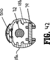
ステープリングデバイス10が完全接近位置にある場合、つまりアンビル組立体30およびシェル組立体31が並列アラインメント状態になって、組織収容隙間(図46)を画定する場合、スクリューストップ306は、回転可能スリーブ33の本体部分42に当接し、つまり、スリーブ33は接近機構のストップとして機能する。図48参照。この位置では、アンビル組立体30およびシェル組立体31はわずかに離間して、組織収容隙間を画定する。カム調節部材400を設けることにより、組織収容隙間は、スクリュー32上のスクリューストップ306の位置を調節して、所望の範囲内になるように選択的に調節することができる。好ましくは、カム調節部材400は、±.045インチの組織収容隙間を調節することが可能だが、これより大きいかまたは小さい調節能力も考えられる。一般に、組織収容隙間の調節は、デバイスの操作者が行なう。別法によると、孔または開口部は、調節部材400に直接触れて、執刀医またはその他の医療従事者が現場で組織収容隙間を調節できるように、ハンドル部分12(図1)に設けられる。
When the stapling device 10 is in a fully approached position, i.e., when the
(インディケータ機構)
図3〜図5および図29を参照すると、インディケータ機構は、球根状インディケータ24と、レンズカバー24aと、摺動部材500とを備える。インディケータ24は、枢動部材502の周囲に枢動可能に支持される。インディケータ24は、ハンドルセクション18aおよび18bと一体に形成することが好ましい。レンズカバー24aはインディケータ24上に配置し、インディケータ24の容易な視認性を促進するために、拡大材料から形成することが好ましい。摺動部材500は、長形スロット506が内部に形成された本体部分504と、遠位の当接部材、または上方に折り返されたリップ部分508と、近位の延在部分510とを備える。摺動部材500は、ハンドルセクション18aおよび18b間に摺動可能に配置される。近位の延在部分510は、ハンドルセクション18aおよび18bと一体に成形され得る支持構造(図5)により、固定ハンドル18内に摺動可能に支持される。付勢部材、好ましくはコイルばね512は、支持構造516と、摺動部材500の本体部分504との間の近位の延在部分510の周囲に圧縮して配置され、摺動部材500を遠位に固定ハンドル18内に圧迫する。インディケータ24は、1対の下方に延在する突出部518および520(図32)を備える。摺動部材500の上方に折り返されたリップ部分508は、突出部518および520間に配置され、固定ハンドル18内で移動する時に、突出部518および520に係合するように配置される。デバイス10の非発射位置では、付勢部材512は、摺動部材500を遠位に圧迫し、リップ部分508を突出部518に係合させてインディケータを第1位置に枢動させ、デバイスがまだ接近せず、発射可能状態にないことを執刀医に知らせる。
(Indicator mechanism)
3 to 5 and 29, the indicator mechanism includes a
上記のとおり、スクリューストップ306は、スクリュー32(図33)に固定して取り付けられる。スクリューストップ306は、第1当接部分または係合部材522を備え、これは、摺動部材500のスロット506を通って移動し、デバイスの接近時にスロット506の近位端506a(図29)に係合する。係合部材522がスロット506の近位端に当接すると、デバイス10がさらに接近し、ばね512の付勢に対抗して、摺動プレート500を固定ハンドル18内の近位に移動させ、その結果、摺動部材500の上方に折り返されたリップ508はインディケータ24の突出部520に係合する。突出部520とリップ508との間の係合により、インディケータ24は、枢動部材502の周囲で第2位置に枢動する。第2位置では、インディケータ24は、デバイスが接近し、発射可能位置になったことを執刀医に知らせる。図48参照。
As described above, the
(発射ロックアウト機構)
図3〜図5および図30を参照すると、発射ロックアウト機構はトリガロック26およびロックアウト部材530を備える。トリガロック26は、ハンドルセクション18aおよび18bのボア532(図3)内に、枢動部材534周囲で枢動可能に支持される。枢動部材534は、好ましくはT形であり、ボア532の内壁に摩擦的に係合し、トリガロック26の回転を防止する。別法によると、その他の枢動部材構成が考えられ、たとえば円形、方形などがある。トリガロック26の先端26aは、発射トリガ20の本体部分76上にある当接部分89と91との間に配置され、トリガロック26が係止位置にある時に、トリガ20が作動するのを防止する。トリガロック26は、以下でさらに詳細に説明するように、近位の延在部分26bも備える。
(Launch lockout mechanism)
With reference to FIGS. 3-5 and 30, the firing lockout mechanism includes a
ロックアウト部材530は、本体部分536と、近位の延在部分538と、1対の前部脚部540aと、1対の後部脚部540bと、当接部材または下方に折り返されたリップ部分542とを備える。ロックアウト部材530は、ハンドルセクション18aおよび18bの内壁上に形成された第1および第2ストップ544と546(図5)との間に摺動可能に配置される。ストップ544は後部脚部540bに係合するように配置され、ストップ546は、前部脚部540aに係合するように配置される。単一の当接部材を各々の対の脚部に置き換えることも考えられる。付勢部材、好ましくはコイルばね549は、ストップ544と本体536との間の近位の延在部分538周囲に配置され、脚部540がストップ546に当接する最も遠位の位置にロックアウト530を圧迫する。この位置では、トリガロック26の延在部分26bは、ロックアウト部材530のリップ部分542の下側に配置され、トリガロック26が枢動部材534の周囲で枢動するのを防止し、ひいてはステープリングデバイス10の発射を防止する。
上記のとおり、スクリューストップ306は、スクリュー32に固定される。1個または複数の第2係合部材548は、スクリューストップ306(図23)から下方に延在する。ステープリングデバイス10が接近し、スクリュー32が固定ハンドル18内で近位に移動すると、係合部材548は、ロックアウト部材530の遠位の脚部540a(図47)に当接し、ロックアウト部材530をばね部材549の付勢に対抗して近位に、リップ部分542がトリガロック26の延在部分26bの近位に離間する位置に移動させる。ロックアウト部材530のこの位置では、トリガロック526は、枢動部材534の周囲で枢動可能であり、ステープリングデバイス10の発射を可能にする。
As described above, the
(触知式インディケータ機構)
図3、図5、図9および図9Aを参照すると、固定ハンドル18内に設けられた触知式インディケータ機構は、ハンドルセクション18aおよび18b内に画定された垂直スロット582内に摺動可能に配置された当接部材580を備える。当接部材580は突起580aと、ガイドリブ580bとを備える。突起580aは、スロット582の壁部に沿って形成された2個の戻り止め582aおよび582bの1個内に収容される寸法に作られる。当接部材580は、突起580aが戻り止め582a内に配置される後退(下方)位置から、突起580aが戻り止め582b内に配置される延在(上方)位置に移動可能である。突起580aと戻り止め582aおよび582bとの間の係合は、当接部材580をそれぞれ上方位置または下方位置に維持する。
(Tactile indicator mechanism)
Referring to FIGS. 3, 5, 9 and 9A, the tactile indicator mechanism provided in the fixed
ステープリングデバイス10の発射前、当接部材580は後退(下方)位置に位置する。デバイス10が発射されると、発射リンク72の延在部分590(図3)は当接部材580に係合し、当接部材580をその後退位置から延在位置に移動させる。延在位置では、当接部材580は、固定ハンドル18のチャネル111内に延在する。
Prior to firing of the stapling device 10, the
スクリューストップ306は、固定ハンドル18のチャネル111内に摺動可能に配置された1対のウィング584を備える。ステープリングデバイス10が発射された後、当接部材580はチャネル111内に配置される。アンビル組立体30およびカートリッジ組立体31の非接近時には、スクリューストップ306のウィング584は当接部材580に係合し、当接部材580を逆に後退(下方)位置に圧迫する。当接部材580とスクリューストップ306のウィング584との間の係合は、アンビルおよびカートリッジ組立体30および31が予め決められた量だけ接近していないことを執刀医に対して触知式および/または可聴式で指示する。好ましくは、当接部材580は、アンビルおよびカートリッジ組立体が、アンビルヘッド組立体が傾斜するのに十分な距離だけ分離する時点で、スクリューストップ306のウィング584に係合するように配置される。したがって、当接部材580とスクリューストップ306のウィング584との間の係合は、アンビルヘッド組立体120が傾斜し、ステープリングデバイス10を患者から取り出すことが可能であることを執刀医に対して触知式および/または可聴式で指示する。
The
(動作)
次に、外科手術用ステープリングデバイス10の動作について、図31〜図61に関して詳細に説明する。
(Operation)
The operation of the surgical stapling device 10 will now be described in detail with respect to FIGS.
図31〜図35は、アンビル組立体をアンビルリテーナ38に取り付ける前の非接近位置つまり開放位置にある外科手術用ステープリングデバイス10を示す。この位置では、付勢部材106(図33)は、カップリング86に係合し、プッシャリンク74を、カップリング86がスクリューストップ306に当接する最も近位の位置に圧迫する。付勢部材512は、インディケータ機構の摺動部材500に係合し、摺動部材500をインディケータ24の突出部518に係合するように配置して、インディケータ24を図33に示すように時計方向に枢動させる。付勢部材549は、ロックアウト部材530の本体536に係合し、ロックアウト部材530を最も遠位の位置に圧迫し、この位置では、ロックアウト部材530のリップ部分542がトリガロック26の延在部分26b上に配置され、トリガロック26が非錠止位置に移動するのを防止する。付勢部材82aも、枢動部材79(図32)に係合して、枢動部材79を垂直スロット82の基部に圧迫し、触知式インディケータ580は後退位置つまり下方位置になり、突出部580aは戻り止め582aで位置決めされる。
FIGS. 31-35 show the surgical stapling device 10 in an inaccessible or open position prior to attaching the anvil assembly to the
図36〜図44は、アンビル組立体30がアンビルリテーナ38に取り付けられ、アンビル組立体30が非接近位置つまり開放位置にある外科手術用ステープリングデバイス10を示す。図37および図38を参照すると、アンビル組立体30をアンビルリテーナ38に取り付ける時、アンビルリテーナ38は、アンビル組立体30の中心ロッド154のボア170内に配置される。可撓性アーム155は外側に偏向して、中心ロッド154を収容する。中心ロッド154は、アンビルリテーナ38上に、図37に矢印「K」で示す方向に前進して、可撓性アーム155の内側肩状部155bは、アンビルリテーナ38上に形成された環状突出部177上を通過する。この時点では、弾性脚部155は、アンビルリテーナに解除自在に係合する。ステープリングデバイスの他の構成部品の位置は、アンビル組立体30をアンビルリテーナ38に取り付けることにより影響を受けず、上記で説明し、図31〜図35に示す状態を保つ。
36-44 show the surgical stapling device 10 with the
図45〜図50は、アンビル組立体30およびカートリッジ組立体31が接近位置つまり閉鎖位置に移動する時の外科手術用ステープリングデバイス10を示す。上記のとおり、アンビル組立体30は、回転ノブ22を図45に矢印「L」で示す方向に回転させることにより、接近位置つまり閉鎖位置に移動する。ノブ22が回転すると、円筒状スリーブ33が回転し、ピン52をスクリュー32の螺旋状チャネル50に沿って移動させる。図48参照。ピン52が螺旋状チャネル50に沿って移動すると、スクリュー32は、スリーブ33内で近位に平行移動する。スクリュー32の遠位端は、遠位端においてアンビルリテーナ38(図46)に固締されるスクリュー延在部分34および36に接続される。したがって、スリーブ33におけるスクリュー32の後退は、アンビルリテーナ38およびアンビル組立体30の近位の移動に変換される。アンビル組立体30が接近すると、中心ロッド154の可撓性脚部155は、アンビル組立体30が接近すると、中心ロッド154の可撓性脚部155はブシュ209内に引き込まれ、脚部155をアンビルリテーナ38上に錠止する。
FIGS. 45-50 show the surgical stapling device 10 when the
図47〜図49を参照すると、スクリューストップ306は、セットスクリュー312により軸方向にスクリュー32に固定される。したがって、スクリュー32がスリーブ33内に後退すると、スクリューストップ306は、固定ハンドル18内の遠位の位置から近位の位置に移動する。スクリューストップ306が遠位の位置から近位の位置に移動すると、スクリューストップ306上に形成された第1係合部材522は、摺動プレート500(図29)のスロット506の近位端506aに当接し、摺動プレート500をばね512の付勢に対抗して近位に移動させる。摺動プレートが近位に移動すると、摺動部材500のリップ508(図48)は、インディケータ24の突出部520に係合し、インディケータ24を図48に示す反時計方向に枢動させる。
Referring to FIGS. 47 to 49, the
スクリューストップ306は、第2係合部材548(図47)も備える。スクリューストップ306が、アンビル組立体30の接近時に遠位の位置から近位の位置に移動すると、第2係合部材548は、ロックアウト部材530の遠位の脚部540aに係合し、ロックアウト部材530を近位に、リップ部分542がトリガロック26の延在部分26bの近位に離間する位置に移動させる。この位置では、トリガロック26は非錠止位置に枢動して、ステープリングデバイス10の発射を可能にする。
The
スクリューストップ306が固定ハンドル18内の最も近位の位置に移動すると、スクリューストップ306の当接部分の表面307を発射リンク72の枢動部材79に係合する位置に配置する。当接部分の表面307は、実質的に凹状の表面を備え、この表面は、ステープリングデバイスの発射時に、枢軸79を部分的に捕捉し、枢軸79のバックストップとして作用するように配置される。
As the screw stop 306 moves to the most proximal position within the fixed
図51〜図56は、発射トリガ20の発射行程における外科手術用ステープリングデバイス10を示す。トリガ20が、固定ハンドル方向に、図52に矢印「M」で指示する方向に圧縮されると、枢動部材79は、スクリューストップ306上の当接部分の表面307に係合し、発射トリガ20が遠位に押される。上記のとおり、発射トリガ22の遠位端は、結合部材86を介してプッシャリンク74の近位端に接続される。したがって、発射トリガ20が遠位に移動すると、プッシャリンク74は、図52に矢印「N」で指示する方向に遠位に移動し、プッシャバック186をシェル組立体31(図52)内において前進させる。プッシャバック186のフィンガ190は、ステープル230をステープルガイド192から押し出す。
FIGS. 51-56 show the surgical stapling device 10 during the firing stroke of the firing
円筒状ナイフ188は、プッシャバック186と同時に移動し、その結果、ナイフ188は移動して、切断リング128およびバックアッププレート126に係合する。上記のとおり、切断リング128は、好ましくはポリエチレンから成形し、バックアッププレート126は、好ましくは金属から成形する。ナイフ188は、切断リング128に係合すると、切断リング128に切り込み、バックアッププレート126をアンビルヘッド124内にさらに深く押し入れて、タブ150(図56)を移動させて、中心ロッド154(図56)の上面154aから離脱させる。次に、アンビルヘッド124は、部材164の周囲で自由に枢動し、プランジャ156により枢動するように促進される。アンビル組立体はシェル組立体31と並列アラインメントされているため、アンビルヘッド14は、アンビルおよびシェル組立体が、アンビルヘッドが完全に枢動するのに十分な距離だけ非接近状態になるまで、完全には枢動しないことに注意する。バックアッププレート126がアンビルヘッド124内に移動すると、リテーナクリップ127(図55)の可撓性アーム127aおよび127bは、外側にバックアッププレート126の前面の位置に跳ねて、バックアッププレート126がアンビルヘッド124から移動するのを妨げる。上記のとおり、アーム127aおよび127bは、アンビル組立体30が非接近位置に戻った時に、バックアッププレート126がナイフ188に付着するのを防止する。
The
図53および図54を参照すると、トリガ20が作動する、つまり固定ハンドル18方向に圧迫されると、発射リンク72の延在部分590は当接部材580方向に枢動して当接部材580に係合し、当接部材580を後退位置から延在位置に移動させる。当接部材は、その延在位置では、固定ハンドル18のチャネル111を遮断する。
53 and 54, when the
図57〜図60を参照すると、デバイス10が発射された後、ステープリングデバイス10が非接近状態にある時、スクリューストップ306のウィング584は、アンビルヘッド124が、傾斜した減少プロファイル位置に枢動することが可能な非接近位置において、触知式インディケータ580(図58)に係合する。ウィング584と触知式インディケータ580との間の接触は、アンビルヘッド124が傾斜したことを触知式および/または可聴式の指示を提供する。追加の力が接近ノブ22に与えられると、スクリューストップ306のウィング584は、触知式インディケータを後退位置に強制し、ステープリングデバイス10が完全開放位置に移動することを可能にする。この位置では、可撓性アーム155は、ブシュ209の遠位に位置し、アンビル組立体30はアンビルリテーナ28から離脱することができる。
Referring to FIGS. 57-60, after the device 10 is fired, when the stapling device 10 is in an inaccessible state, the
本明細書に開示した実施態様には、様々な変更を加えることができることが分かるであろう。したがって、上記の説明は、制限的なものではなく、好ましい実施態様を例示しているにすぎないと考えるべきである。当業者は、本明細書に添付する請求項の範囲および精神の範囲内で、その他の変更を想像するであろう。たとえば、上記の説明は、もっぱらステープルについて述べているが、ステープルは、2部式固締具などの異なるタイプの組織固締具を備えることが想像される。2部式固締具を適用するステープリングデバイスの場合、ステープリングデバイスのアンビル組立体は、各々の2部式固締具の一方の部分を支持するであろう。 It will be appreciated that various modifications can be made to the embodiments disclosed herein. Accordingly, the above description should not be construed as limiting, but merely as exemplifications of preferred embodiments. Those skilled in the art will envision other modifications within the scope and spirit of the claims appended hereto. For example, while the above description has described exclusively for staples, it is envisioned that staples comprise different types of tissue fasteners, such as two-part fasteners. In the case of a stapling device applying a two-part fastener, the anvil assembly of the stapling device will support one part of each two-part fastener.
ここに開示する外科手術用ステープリングデバイスの様々な好ましい実施態様について、図面に関して本明細書で開示する。
Claims (3)
発射トリガを含むハンドル組立体と、
該ハンドル組立体から遠位に延在する本体部分と、
アンビル組立体およびシェル組立体を備えるヘッド部分であって、該アンビル組立体が該シェル組立体に対して、離間位置と接近位置との間で移動可能なヘッド部分と、
インディケータであって、該インディケータが、該ハンドル組立体上に配置され、該デバイスの少なくとも1つの側面からインディケータを見ることを容易にするための球根状の形状を有し、該アンビル組立体およびカートリッジ組立体が接近位置に移動するのに応じて、第1位置から第2位置に移動可能で、該アンビル組立体が接近位置にあることを執刀医に視覚的に指示するインディケータと、
該インディケータを少なくとも部分的に覆うように配置されたレンズであって、拡大材料から形成されたレンズと、
該ハンドル組立体内に配置され、少なくとも部分的に該本体部分を通って延在する接近機構であって、該デバイス内で移動可能であり、該アンビル組立体を離間位置と接近位置との間で移動させる、接近機構と
該インディケータに動作可能に結合し、該ハンドル組立体内で移動可能な摺動部材であって、前進位置から後退位置に移動可能であり、該インディケータを第1位置から第2位置に移動させる、摺動部材とを備え、
ここで、該接近機構が、該ハンドル組立体内で線形移動可能なスクリュー部材を備え、該スクリュー部材の上に当接部材が支持され、該当接部材が、該スクリュー部材と共に移動可能であり、該摺動部材が、内部に形成された長形スロットを含み、該当接部材が該長形スロット内で移動可能であって、該スロットの近位端に係合し、該摺動部材をその前進位置から後退位置に移動させ、該インディケータが、該ハンドル組立体内に枢動可能に支持される、
外科手術用ステープリングデバイス。A surgical stapling device comprising:
A handle assembly including a firing trigger;
A body portion extending distally from the handle assembly;
A head portion comprising an anvil assembly and a shell assembly, wherein the anvil assembly is movable relative to the shell assembly between a spaced position and an approach position;
An indicator, wherein the indicator is disposed on the handle assembly and has a bulbous shape to facilitate viewing of the indicator from at least one side of the device, the anvil assembly and cartridge An indicator that is movable from a first position to a second position in response to the assembly moving to the approach position and visually indicating to the surgeon that the anvil assembly is in the approach position ;
A lens arranged to at least partially cover the indicator, wherein the lens is formed from a magnifying material;
An access mechanism disposed within the handle assembly and extending at least partially through the body portion, the access mechanism being movable within the device, wherein the anvil assembly is moved between a spaced position and an access position; Move, with approach mechanism
A sliding member operably coupled to the indicator and movable within the handle assembly, wherein the sliding member is movable from an advanced position to a retracted position and moves the indicator from a first position to a second position. A moving member,
Here, the approach mechanism includes a screw member that is linearly movable in the handle assembly, a contact member is supported on the screw member, and the corresponding contact member is movable together with the screw member. The sliding member includes an elongated slot formed therein, the corresponding contact member being movable within the elongated slot, engaging the proximal end of the slot, and moving the sliding member forward Moving from a position to a retracted position, the indicator being pivotally supported in the handle assembly;
Surgical stapling device.
前記アンビル組立体が、
ポストを有するアンビルヘッドと、複数のステープル形成ポケットを備えるアンビルと、第1位置から第2位置に摺動可能にポストの周囲に配置された切断リングと、
該アンビルヘッドのポストから延在するアンビル中心ロッドと、
該アンビルヘッドのポスト上に配置されたリテーナクリップであって、少なくとも1個の弾性アームを有し、非付勢状態で、該ポストから外側に延在するリテーナクリップとを備え、
第1位置で、該切断リングが該弾性アームに少なくとも部分的に係合して、該弾性アームを該切断リングの移動経路から離脱するように促進し、第2位置で、該リテーナクリップの弾性アームが、該切断リングの移動経路内に突出して、該切断リングがその第2位置から逆に第1位置に移動するのを防止する、外科手術用ステープリングデバイス。 The surgical stapling device according to claim 1, comprising:
The anvil assembly is
An anvil head having a post, a plurality of the anvil having staple-forming pockets, the cutting ring from a first position disposed around slidably post the second position,
An anvil center rod extending from the post of the anvil head;
A retainer clip positioned on the post of the anvil head has at least one resilient arm, in a non-energized state, and a retainer clip extending outwardly from said post,
In a first position, the cutting ring is at least partially engaged with the elastic arm to facilitate disengagement of the elastic arm from the path of movement of the cutting ring, and in a second position, the elasticity of the retainer clip. A surgical stapling device , wherein an arm protrudes into a path of movement of the cutting ring to prevent the cutting ring from moving back from its second position to the first position.
ここで、前記アンビルヘッドが、枢動部材により、前記アンビル中心ロッドに枢動可能に取り付けられ、該リテーナクリップが、前記枢動部材を収容して、該リテーナクリップを前記ポストに固定するための凹部を備え、前記切断リングが、前記切断リングに固定されたバックアッププレートを備え、該バックアッププレートが、該切断リングが第1位置にある場合に、アンビルヘッドがアンビル中心ロッドに対して枢動することを防止するように配置された少なくとも1個のタブを有する、
外科手術用ステープリングデバイス。The surgical stapling device of claim 2 , wherein the anvil head post includes a transverse slot formed therein, the retainer clip is disposed within the transverse slot, and the retainer clip is 1 A pair of resilient arms, wherein when the cutting ring is in the second position, one arm extends from each side of the transverse slot, and in the first position, the cutting ring is in the transverse slot of the post Arranged around and engaging the resilient arm, compressing the resilient arm of the retainer clip into the transverse slot;
Wherein the anvil head is pivotally attached to the anvil center rod by a pivot member, and the retainer clip receives the pivot member and secures the retainer clip to the post. A recess, wherein the cutting ring includes a backup plate secured to the cutting ring, the anvil head pivoting relative to the anvil center rod when the backup plate is in the first position Having at least one tab arranged to prevent
Surgical stapling device .
Applications Claiming Priority (2)
| Application Number | Priority Date | Filing Date | Title |
|---|---|---|---|
| US41605502P | 2002-10-04 | 2002-10-04 | |
| PCT/US2003/031638 WO2004032766A2 (en) | 2002-10-04 | 2003-10-06 | Surgical stapling device |
Related Child Applications (1)
| Application Number | Title | Priority Date | Filing Date |
|---|---|---|---|
| JP2009244983A Division JP4898888B2 (en) | 2002-10-04 | 2009-10-23 | Surgical stapling device |
Publications (3)
| Publication Number | Publication Date |
|---|---|
| JP2006501950A JP2006501950A (en) | 2006-01-19 |
| JP2006501950A5 JP2006501950A5 (en) | 2006-10-05 |
| JP4422027B2 true JP4422027B2 (en) | 2010-02-24 |
Family
ID=32093804
Family Applications (3)
| Application Number | Title | Priority Date | Filing Date |
|---|---|---|---|
| JP2004543410A Expired - Fee Related JP4422027B2 (en) | 2002-10-04 | 2003-10-06 | Surgical stapling device |
| JP2009244983A Expired - Fee Related JP4898888B2 (en) | 2002-10-04 | 2009-10-23 | Surgical stapling device |
| JP2011219384A Pending JP2012024608A (en) | 2002-10-04 | 2011-10-03 | Surgical stapling device |
Family Applications After (2)
| Application Number | Title | Priority Date | Filing Date |
|---|---|---|---|
| JP2009244983A Expired - Fee Related JP4898888B2 (en) | 2002-10-04 | 2009-10-23 | Surgical stapling device |
| JP2011219384A Pending JP2012024608A (en) | 2002-10-04 | 2011-10-03 | Surgical stapling device |
Country Status (8)
| Country | Link |
|---|---|
| US (4) | US7303106B2 (en) |
| EP (2) | EP2055246B1 (en) |
| JP (3) | JP4422027B2 (en) |
| AU (2) | AU2003279147B2 (en) |
| CA (2) | CA2501049C (en) |
| DE (1) | DE60327227D1 (en) |
| ES (2) | ES2385522T3 (en) |
| WO (1) | WO2004032766A2 (en) |
Families Citing this family (828)
| Publication number | Priority date | Publication date | Assignee | Title |
|---|---|---|---|---|
| US20070060952A1 (en) * | 2005-09-02 | 2007-03-15 | Roby Mark S | Surgical stapling device with coated knife blade |
| US10285694B2 (en) | 2001-10-20 | 2019-05-14 | Covidien Lp | Surgical stapler with timer and feedback display |
| US7464847B2 (en) | 2005-06-03 | 2008-12-16 | Tyco Healthcare Group Lp | Surgical stapler with timer and feedback display |
| CA2501049C (en) | 2002-10-04 | 2012-01-03 | Tyco Healthcare Group Lp | Surgical stapling device |
| US20070084897A1 (en) | 2003-05-20 | 2007-04-19 | Shelton Frederick E Iv | Articulating surgical stapling instrument incorporating a two-piece e-beam firing mechanism |
| US9060770B2 (en) | 2003-05-20 | 2015-06-23 | Ethicon Endo-Surgery, Inc. | Robotically-driven surgical instrument with E-beam driver |
| ES2551683T3 (en) | 2003-06-20 | 2015-11-23 | Covidien Lp | Surgical stapling instrument |
| ES2380921T3 (en) | 2003-10-17 | 2012-05-21 | Tyco Healthcare Group Lp | Surgical stapling device |
| US8181840B2 (en) | 2004-03-19 | 2012-05-22 | Tyco Healthcare Group Lp | Tissue tensioner assembly and approximation mechanism for surgical stapling device |
| US8215531B2 (en) | 2004-07-28 | 2012-07-10 | Ethicon Endo-Surgery, Inc. | Surgical stapling instrument having a medical substance dispenser |
| US8905977B2 (en) | 2004-07-28 | 2014-12-09 | Ethicon Endo-Surgery, Inc. | Surgical stapling instrument having an electroactive polymer actuated medical substance dispenser |
| US11896225B2 (en) | 2004-07-28 | 2024-02-13 | Cilag Gmbh International | Staple cartridge comprising a pan |
| AU2006255303B2 (en) | 2005-06-03 | 2011-12-15 | Covidien Lp | Battery powered surgical instrument |
| US7717312B2 (en) | 2005-06-03 | 2010-05-18 | Tyco Healthcare Group Lp | Surgical instruments employing sensors |
| US11291443B2 (en) | 2005-06-03 | 2022-04-05 | Covidien Lp | Surgical stapler with timer and feedback display |
| US7407075B2 (en) * | 2005-08-15 | 2008-08-05 | Tyco Healthcare Group Lp | Staple cartridge having multiple staple sizes for a surgical stapling instrument |
| US7669746B2 (en) | 2005-08-31 | 2010-03-02 | Ethicon Endo-Surgery, Inc. | Staple cartridges for forming staples having differing formed staple heights |
| US7934630B2 (en) | 2005-08-31 | 2011-05-03 | Ethicon Endo-Surgery, Inc. | Staple cartridges for forming staples having differing formed staple heights |
| US11484312B2 (en) | 2005-08-31 | 2022-11-01 | Cilag Gmbh International | Staple cartridge comprising a staple driver arrangement |
| US8800838B2 (en) | 2005-08-31 | 2014-08-12 | Ethicon Endo-Surgery, Inc. | Robotically-controlled cable-based surgical end effectors |
| US11246590B2 (en) | 2005-08-31 | 2022-02-15 | Cilag Gmbh International | Staple cartridge including staple drivers having different unfired heights |
| US9237891B2 (en) | 2005-08-31 | 2016-01-19 | Ethicon Endo-Surgery, Inc. | Robotically-controlled surgical stapling devices that produce formed staples having different lengths |
| US10159482B2 (en) | 2005-08-31 | 2018-12-25 | Ethicon Llc | Fastener cartridge assembly comprising a fixed anvil and different staple heights |
| US7673781B2 (en) | 2005-08-31 | 2010-03-09 | Ethicon Endo-Surgery, Inc. | Surgical stapling device with staple driver that supports multiple wire diameter staples |
| US7673783B2 (en) | 2005-11-04 | 2010-03-09 | Ethicon Endo-Surgery, Inc. | Surgical stapling instruments structured for delivery of medical agents |
| US20070106317A1 (en) | 2005-11-09 | 2007-05-10 | Shelton Frederick E Iv | Hydraulically and electrically actuated articulation joints for surgical instruments |
| US7799039B2 (en) | 2005-11-09 | 2010-09-21 | Ethicon Endo-Surgery, Inc. | Surgical instrument having a hydraulically actuated end effector |
| US7673780B2 (en) | 2005-11-09 | 2010-03-09 | Ethicon Endo-Surgery, Inc. | Articulation joint with improved moment arm extension for articulating an end effector of a surgical instrument |
| US11278279B2 (en) | 2006-01-31 | 2022-03-22 | Cilag Gmbh International | Surgical instrument assembly |
| US7845537B2 (en) | 2006-01-31 | 2010-12-07 | Ethicon Endo-Surgery, Inc. | Surgical instrument having recording capabilities |
| US7568603B2 (en) | 2006-01-31 | 2009-08-04 | Ethicon Endo-Surgery, Inc. | Motor-driven surgical cutting and fastening instrument with articulatable end effector |
| US7644848B2 (en) | 2006-01-31 | 2010-01-12 | Ethicon Endo-Surgery, Inc. | Electronic lockouts and surgical instrument including same |
| US7766210B2 (en) | 2006-01-31 | 2010-08-03 | Ethicon Endo-Surgery, Inc. | Motor-driven surgical cutting and fastening instrument with user feedback system |
| US9861359B2 (en) | 2006-01-31 | 2018-01-09 | Ethicon Llc | Powered surgical instruments with firing system lockout arrangements |
| US8186555B2 (en) | 2006-01-31 | 2012-05-29 | Ethicon Endo-Surgery, Inc. | Motor-driven surgical cutting and fastening instrument with mechanical closure system |
| US20110024477A1 (en) | 2009-02-06 | 2011-02-03 | Hall Steven G | Driven Surgical Stapler Improvements |
| US11224427B2 (en) | 2006-01-31 | 2022-01-18 | Cilag Gmbh International | Surgical stapling system including a console and retraction assembly |
| US7753904B2 (en) | 2006-01-31 | 2010-07-13 | Ethicon Endo-Surgery, Inc. | Endoscopic surgical instrument with a handle that can articulate with respect to the shaft |
| US8708213B2 (en) | 2006-01-31 | 2014-04-29 | Ethicon Endo-Surgery, Inc. | Surgical instrument having a feedback system |
| US7770775B2 (en) | 2006-01-31 | 2010-08-10 | Ethicon Endo-Surgery, Inc. | Motor-driven surgical cutting and fastening instrument with adaptive user feedback |
| US11793518B2 (en) | 2006-01-31 | 2023-10-24 | Cilag Gmbh International | Powered surgical instruments with firing system lockout arrangements |
| US20110006101A1 (en) | 2009-02-06 | 2011-01-13 | EthiconEndo-Surgery, Inc. | Motor driven surgical fastener device with cutting member lockout arrangements |
| US20110290856A1 (en) | 2006-01-31 | 2011-12-01 | Ethicon Endo-Surgery, Inc. | Robotically-controlled surgical instrument with force-feedback capabilities |
| US8161977B2 (en) | 2006-01-31 | 2012-04-24 | Ethicon Endo-Surgery, Inc. | Accessing data stored in a memory of a surgical instrument |
| US20120292367A1 (en) | 2006-01-31 | 2012-11-22 | Ethicon Endo-Surgery, Inc. | Robotically-controlled end effector |
| US8763879B2 (en) | 2006-01-31 | 2014-07-01 | Ethicon Endo-Surgery, Inc. | Accessing data stored in a memory of surgical instrument |
| US8820603B2 (en) | 2006-01-31 | 2014-09-02 | Ethicon Endo-Surgery, Inc. | Accessing data stored in a memory of a surgical instrument |
| US8062236B2 (en) | 2006-02-02 | 2011-11-22 | Tyco Healthcare Group, Lp | Method and system to determine an optimal tissue compression time to implant a surgical element |
| US20070225562A1 (en) | 2006-03-23 | 2007-09-27 | Ethicon Endo-Surgery, Inc. | Articulating endoscopic accessory channel |
| US8992422B2 (en) | 2006-03-23 | 2015-03-31 | Ethicon Endo-Surgery, Inc. | Robotically-controlled endoscopic accessory channel |
| US8540132B2 (en) * | 2006-05-16 | 2013-09-24 | Covidien Lp | Tilt anvil assembly |
| US7552854B2 (en) | 2006-05-19 | 2009-06-30 | Applied Medical Resources Corporation | Surgical stapler with firing lock mechanism |
| US8322455B2 (en) | 2006-06-27 | 2012-12-04 | Ethicon Endo-Surgery, Inc. | Manually driven surgical cutting and fastening instrument |
| US7740159B2 (en) | 2006-08-02 | 2010-06-22 | Ethicon Endo-Surgery, Inc. | Pneumatically powered surgical cutting and fastening instrument with a variable control of the actuating rate of firing with mechanical power assist |
| US20110087276A1 (en) | 2009-10-09 | 2011-04-14 | Ethicon Endo-Surgery, Inc. | Method for forming a staple |
| US10130359B2 (en) | 2006-09-29 | 2018-11-20 | Ethicon Llc | Method for forming a staple |
| US8348131B2 (en) | 2006-09-29 | 2013-01-08 | Ethicon Endo-Surgery, Inc. | Surgical stapling instrument with mechanical indicator to show levels of tissue compression |
| US10568652B2 (en) | 2006-09-29 | 2020-02-25 | Ethicon Llc | Surgical staples having attached drivers of different heights and stapling instruments for deploying the same |
| ES2627615T3 (en) | 2006-10-26 | 2017-07-28 | Covidien Lp | Device that uses alloys with shape memory for buttress connection |
| US7699203B2 (en) * | 2006-11-13 | 2010-04-20 | Warsaw Orthopedic, Inc. | Variable angle surgical staple inserter |
| DE602006012069D1 (en) * | 2006-12-04 | 2010-03-18 | Ethicon Endo Surgery Inc | Tissue clamp for transanal hemorrhoidopexy or hemorrhoidectomy |
| US7900805B2 (en) | 2007-01-10 | 2011-03-08 | Ethicon Endo-Surgery, Inc. | Surgical instrument with enhanced battery performance |
| US7721931B2 (en) | 2007-01-10 | 2010-05-25 | Ethicon Endo-Surgery, Inc. | Prevention of cartridge reuse in a surgical instrument |
| US8652120B2 (en) | 2007-01-10 | 2014-02-18 | Ethicon Endo-Surgery, Inc. | Surgical instrument with wireless communication between control unit and sensor transponders |
| US7954682B2 (en) | 2007-01-10 | 2011-06-07 | Ethicon Endo-Surgery, Inc. | Surgical instrument with elements to communicate between control unit and end effector |
| US8684253B2 (en) | 2007-01-10 | 2014-04-01 | Ethicon Endo-Surgery, Inc. | Surgical instrument with wireless communication between a control unit of a robotic system and remote sensor |
| US11291441B2 (en) | 2007-01-10 | 2022-04-05 | Cilag Gmbh International | Surgical instrument with wireless communication between control unit and remote sensor |
| US7721936B2 (en) | 2007-01-10 | 2010-05-25 | Ethicon Endo-Surgery, Inc. | Interlock and surgical instrument including same |
| US7738971B2 (en) | 2007-01-10 | 2010-06-15 | Ethicon Endo-Surgery, Inc. | Post-sterilization programming of surgical instruments |
| US8459520B2 (en) | 2007-01-10 | 2013-06-11 | Ethicon Endo-Surgery, Inc. | Surgical instrument with wireless communication between control unit and remote sensor |
| US8540128B2 (en) | 2007-01-11 | 2013-09-24 | Ethicon Endo-Surgery, Inc. | Surgical stapling device with a curved end effector |
| US11039836B2 (en) | 2007-01-11 | 2021-06-22 | Cilag Gmbh International | Staple cartridge for use with a surgical stapling instrument |
| DE602007012771D1 (en) | 2007-03-07 | 2011-04-07 | Covidien Ag | CLAMP DEVICE FOR MUCOSEKTOMY |
| US7431188B1 (en) | 2007-03-15 | 2008-10-07 | Tyco Healthcare Group Lp | Surgical stapling apparatus with powered articulation |
| US8727197B2 (en) | 2007-03-15 | 2014-05-20 | Ethicon Endo-Surgery, Inc. | Staple cartridge cavity configuration with cooperative surgical staple |
| US8056787B2 (en) | 2007-03-28 | 2011-11-15 | Ethicon Endo-Surgery, Inc. | Surgical stapling and cutting instrument with travel-indicating retraction member |
| US8893946B2 (en) | 2007-03-28 | 2014-11-25 | Ethicon Endo-Surgery, Inc. | Laparoscopic tissue thickness and clamp load measuring devices |
| US7981124B2 (en) * | 2007-04-04 | 2011-07-19 | Misder, Llc | Medical device for applying purse string sutures |
| US11259801B2 (en) | 2007-04-13 | 2022-03-01 | Covidien Lp | Powered surgical instrument |
| US20080255413A1 (en) | 2007-04-13 | 2008-10-16 | Michael Zemlok | Powered surgical instrument |
| US8800837B2 (en) | 2007-04-13 | 2014-08-12 | Covidien Lp | Powered surgical instrument |
| US7950560B2 (en) | 2007-04-13 | 2011-05-31 | Tyco Healthcare Group Lp | Powered surgical instrument |
| US7823760B2 (en) | 2007-05-01 | 2010-11-02 | Tyco Healthcare Group Lp | Powered surgical stapling device platform |
| US7931660B2 (en) | 2007-05-10 | 2011-04-26 | Tyco Healthcare Group Lp | Powered tacker instrument |
| US7798386B2 (en) | 2007-05-30 | 2010-09-21 | Ethicon Endo-Surgery, Inc. | Surgical instrument articulation joint cover |
| US7810693B2 (en) | 2007-05-30 | 2010-10-12 | Ethicon Endo-Surgery, Inc. | Surgical stapling and cutting instrument with articulatable end effector |
| US8157145B2 (en) | 2007-05-31 | 2012-04-17 | Ethicon Endo-Surgery, Inc. | Pneumatically powered surgical cutting and fastening instrument with electrical feedback |
| US7905380B2 (en) | 2007-06-04 | 2011-03-15 | Ethicon Endo-Surgery, Inc. | Surgical instrument having a multiple rate directional switching mechanism |
| US8534528B2 (en) | 2007-06-04 | 2013-09-17 | Ethicon Endo-Surgery, Inc. | Surgical instrument having a multiple rate directional switching mechanism |
| US8931682B2 (en) | 2007-06-04 | 2015-01-13 | Ethicon Endo-Surgery, Inc. | Robotically-controlled shaft based rotary drive systems for surgical instruments |
| US7832408B2 (en) | 2007-06-04 | 2010-11-16 | Ethicon Endo-Surgery, Inc. | Surgical instrument having a directional switching mechanism |
| US11564682B2 (en) | 2007-06-04 | 2023-01-31 | Cilag Gmbh International | Surgical stapler device |
| US7819299B2 (en) | 2007-06-04 | 2010-10-26 | Ethicon Endo-Surgery, Inc. | Surgical instrument having a common trigger for actuating an end effector closing system and a staple firing system |
| US7604640B2 (en) * | 2007-06-14 | 2009-10-20 | Zimmer Spine Austin, Inc. | Device and system for applying rotary impact |
| US7731072B2 (en) | 2007-06-18 | 2010-06-08 | Ethicon Endo-Surgery, Inc. | Surgical stapling and cutting instrument with improved anvil opening features |
| US7658311B2 (en) | 2007-06-22 | 2010-02-09 | Ethicon Endo-Surgery, Inc. | Surgical stapling instrument with a geared return mechanism |
| US7753245B2 (en) | 2007-06-22 | 2010-07-13 | Ethicon Endo-Surgery, Inc. | Surgical stapling instruments |
| US8308040B2 (en) | 2007-06-22 | 2012-11-13 | Ethicon Endo-Surgery, Inc. | Surgical stapling instrument with an articulatable end effector |
| US11849941B2 (en) | 2007-06-29 | 2023-12-26 | Cilag Gmbh International | Staple cartridge having staple cavities extending at a transverse angle relative to a longitudinal cartridge axis |
| US9820748B2 (en) * | 2007-09-24 | 2017-11-21 | Covidien Lp | Insertion aid with interference fit |
| US7922063B2 (en) | 2007-10-31 | 2011-04-12 | Tyco Healthcare Group, Lp | Powered surgical instrument |
| US8011554B2 (en) * | 2008-01-09 | 2011-09-06 | Tyco Healthcare Group, Lp | Raised boss for staple guide |
| US7766209B2 (en) | 2008-02-13 | 2010-08-03 | Ethicon Endo-Surgery, Inc. | Surgical stapling instrument with improved firing trigger arrangement |
| US8453908B2 (en) | 2008-02-13 | 2013-06-04 | Ethicon Endo-Surgery, Inc. | Surgical stapling instrument with improved firing trigger arrangement |
| US8561870B2 (en) | 2008-02-13 | 2013-10-22 | Ethicon Endo-Surgery, Inc. | Surgical stapling instrument |
| US8540133B2 (en) | 2008-09-19 | 2013-09-24 | Ethicon Endo-Surgery, Inc. | Staple cartridge |
| US7866527B2 (en) | 2008-02-14 | 2011-01-11 | Ethicon Endo-Surgery, Inc. | Surgical stapling apparatus with interlockable firing system |
| US9179912B2 (en) | 2008-02-14 | 2015-11-10 | Ethicon Endo-Surgery, Inc. | Robotically-controlled motorized surgical cutting and fastening instrument |
| US8622274B2 (en) | 2008-02-14 | 2014-01-07 | Ethicon Endo-Surgery, Inc. | Motorized cutting and fastening instrument having control circuit for optimizing battery usage |
| US7810692B2 (en) | 2008-02-14 | 2010-10-12 | Ethicon Endo-Surgery, Inc. | Disposable loading unit with firing indicator |
| US7861906B2 (en) | 2008-02-14 | 2011-01-04 | Ethicon Endo-Surgery, Inc. | Surgical stapling apparatus with articulatable components |
| RU2493788C2 (en) | 2008-02-14 | 2013-09-27 | Этикон Эндо-Серджери, Инк. | Surgical cutting and fixing instrument, which has radio-frequency electrodes |
| US7913891B2 (en) | 2008-02-14 | 2011-03-29 | Ethicon Endo-Surgery, Inc. | Disposable loading unit with user feedback features and surgical instrument for use therewith |
| US8459525B2 (en) | 2008-02-14 | 2013-06-11 | Ethicon Endo-Sugery, Inc. | Motorized surgical cutting and fastening instrument having a magnetic drive train torque limiting device |
| US8752749B2 (en) | 2008-02-14 | 2014-06-17 | Ethicon Endo-Surgery, Inc. | Robotically-controlled disposable motor-driven loading unit |
| US8573465B2 (en) | 2008-02-14 | 2013-11-05 | Ethicon Endo-Surgery, Inc. | Robotically-controlled surgical end effector system with rotary actuated closure systems |
| US7793812B2 (en) | 2008-02-14 | 2010-09-14 | Ethicon Endo-Surgery, Inc. | Disposable motor-driven loading unit for use with a surgical cutting and stapling apparatus |
| US8584919B2 (en) | 2008-02-14 | 2013-11-19 | Ethicon Endo-Sugery, Inc. | Surgical stapling apparatus with load-sensitive firing mechanism |
| US8636736B2 (en) | 2008-02-14 | 2014-01-28 | Ethicon Endo-Surgery, Inc. | Motorized surgical cutting and fastening instrument |
| US7819296B2 (en) | 2008-02-14 | 2010-10-26 | Ethicon Endo-Surgery, Inc. | Surgical stapling apparatus with retractable firing systems |
| US7819298B2 (en) | 2008-02-14 | 2010-10-26 | Ethicon Endo-Surgery, Inc. | Surgical stapling apparatus with control features operable with one hand |
| US7857185B2 (en) | 2008-02-14 | 2010-12-28 | Ethicon Endo-Surgery, Inc. | Disposable loading unit for surgical stapling apparatus |
| US8758391B2 (en) | 2008-02-14 | 2014-06-24 | Ethicon Endo-Surgery, Inc. | Interchangeable tools for surgical instruments |
| US7819297B2 (en) | 2008-02-14 | 2010-10-26 | Ethicon Endo-Surgery, Inc. | Surgical stapling apparatus with reprocessible handle assembly |
| US8657174B2 (en) | 2008-02-14 | 2014-02-25 | Ethicon Endo-Surgery, Inc. | Motorized surgical cutting and fastening instrument having handle based power source |
| US20130153641A1 (en) | 2008-02-15 | 2013-06-20 | Ethicon Endo-Surgery, Inc. | Releasable layer of material and surgical end effector having the same |
| US20090206131A1 (en) | 2008-02-15 | 2009-08-20 | Ethicon Endo-Surgery, Inc. | End effector coupling arrangements for a surgical cutting and stapling instrument |
| US7980443B2 (en) | 2008-02-15 | 2011-07-19 | Ethicon Endo-Surgery, Inc. | End effectors for a surgical cutting and stapling instrument |
| US8608044B2 (en) | 2008-02-15 | 2013-12-17 | Ethicon Endo-Surgery, Inc. | Feedback and lockout mechanism for surgical instrument |
| US7959051B2 (en) | 2008-02-15 | 2011-06-14 | Ethicon Endo-Surgery, Inc. | Closure systems for a surgical cutting and stapling instrument |
| US11272927B2 (en) | 2008-02-15 | 2022-03-15 | Cilag Gmbh International | Layer arrangements for surgical staple cartridges |
| US20090206126A1 (en) | 2008-02-15 | 2009-08-20 | Ethicon Endo-Surgery, Inc. | Buttress material with alignment and retention features for use with surgical end effectors |
| US8733611B2 (en) | 2008-03-12 | 2014-05-27 | Covidien Lp | Ratcheting mechanism for surgical stapling device |
| US7926691B2 (en) | 2008-04-14 | 2011-04-19 | Tyco Healthcare Group, L.P. | Variable compression surgical fastener cartridge |
| US8231040B2 (en) * | 2008-04-14 | 2012-07-31 | Tyco Healthcare Group Lp | Variable compression surgical fastener cartridge |
| US8028884B2 (en) * | 2008-04-22 | 2011-10-04 | Tyco Healthcare Group Lp | Cartridge for applying varying amounts of tissue compression |
| US7922061B2 (en) | 2008-05-21 | 2011-04-12 | Ethicon Endo-Surgery, Inc. | Surgical instrument with automatically reconfigurable articulating end effector |
| US20110040308A1 (en) | 2008-06-13 | 2011-02-17 | Ramiro Cabrera | Endoscopic Stitching Devices |
| US8678264B2 (en) | 2008-07-07 | 2014-03-25 | Covidien Lp | Surgical instrument with elongated channel |
| US8685046B2 (en) * | 2008-08-05 | 2014-04-01 | Covidien Lp | Magnetic compression anastomosis device |
| AU2015202752B2 (en) * | 2008-08-12 | 2016-05-19 | Covidien Lp | Surgical tilt anvil assembly |
| AU2016210627B2 (en) * | 2008-08-12 | 2017-07-13 | Covidien Lp | Surgical tilt anvil assembly |
| US8109426B2 (en) | 2008-08-12 | 2012-02-07 | Tyco Healthcare Group Lp | Surgical tilt anvil assembly |
| US20100051668A1 (en) | 2008-09-03 | 2010-03-04 | Milliman Keith L | Surgical instrument with indicator |
| US8113405B2 (en) | 2008-09-03 | 2012-02-14 | Tyco Healthcare Group, Lp | Surgical instrument with indicator |
| US8181838B2 (en) | 2008-09-10 | 2012-05-22 | Tyco Healthcare Group Lp | Surgical stapling device |
| US8083120B2 (en) | 2008-09-18 | 2011-12-27 | Ethicon Endo-Surgery, Inc. | End effector for use with a surgical cutting and stapling instrument |
| US7837080B2 (en) | 2008-09-18 | 2010-11-23 | Ethicon Endo-Surgery, Inc. | Surgical stapling instrument with device for indicating when the instrument has cut through tissue |
| PL3476312T3 (en) | 2008-09-19 | 2024-03-11 | Ethicon Llc | Surgical stapler with apparatus for adjusting staple height |
| US7954686B2 (en) | 2008-09-19 | 2011-06-07 | Ethicon Endo-Surgery, Inc. | Surgical stapler with apparatus for adjusting staple height |
| US9386983B2 (en) | 2008-09-23 | 2016-07-12 | Ethicon Endo-Surgery, Llc | Robotically-controlled motorized surgical instrument |
| US11648005B2 (en) | 2008-09-23 | 2023-05-16 | Cilag Gmbh International | Robotically-controlled motorized surgical instrument with an end effector |
| US8210411B2 (en) | 2008-09-23 | 2012-07-03 | Ethicon Endo-Surgery, Inc. | Motor-driven surgical cutting instrument |
| US9050083B2 (en) | 2008-09-23 | 2015-06-09 | Ethicon Endo-Surgery, Inc. | Motorized surgical instrument |
| US9005230B2 (en) | 2008-09-23 | 2015-04-14 | Ethicon Endo-Surgery, Inc. | Motorized surgical instrument |
| US8279242B2 (en) * | 2008-09-26 | 2012-10-02 | Microsoft Corporation | Compensating for anticipated movement of a device |
| US8608045B2 (en) | 2008-10-10 | 2013-12-17 | Ethicon Endo-Sugery, Inc. | Powered surgical cutting and stapling apparatus with manually retractable firing system |
| US8020743B2 (en) | 2008-10-15 | 2011-09-20 | Ethicon Endo-Surgery, Inc. | Powered articulatable surgical cutting and fastening instrument with flexible drive member |
| US8231042B2 (en) | 2008-11-06 | 2012-07-31 | Tyco Healthcare Group Lp | Surgical stapler |
| US8408441B2 (en) | 2009-01-06 | 2013-04-02 | Covidien Lp | Surgical stapler |
| US8281974B2 (en) | 2009-01-14 | 2012-10-09 | Tyco Healthcare, Group LP | Surgical stapler with suture locator |
| US8517239B2 (en) | 2009-02-05 | 2013-08-27 | Ethicon Endo-Surgery, Inc. | Surgical stapling instrument comprising a magnetic element driver |
| US8414577B2 (en) | 2009-02-05 | 2013-04-09 | Ethicon Endo-Surgery, Inc. | Surgical instruments and components for use in sterile environments |
| US8397971B2 (en) | 2009-02-05 | 2013-03-19 | Ethicon Endo-Surgery, Inc. | Sterilizable surgical instrument |
| US8485413B2 (en) | 2009-02-05 | 2013-07-16 | Ethicon Endo-Surgery, Inc. | Surgical stapling instrument comprising an articulation joint |
| CA2751664A1 (en) | 2009-02-06 | 2010-08-12 | Ethicon Endo-Surgery, Inc. | Driven surgical stapler improvements |
| US8444036B2 (en) | 2009-02-06 | 2013-05-21 | Ethicon Endo-Surgery, Inc. | Motor driven surgical fastener device with mechanisms for adjusting a tissue gap within the end effector |
| US8453913B2 (en) | 2009-02-06 | 2013-06-04 | Covidien Lp | Anvil for surgical stapler |
| US8418909B2 (en) * | 2009-06-02 | 2013-04-16 | Covidien Lp | Surgical instrument and method for performing a resection |
| US8821514B2 (en) | 2009-06-08 | 2014-09-02 | Covidien Lp | Powered tack applier |
| US8276802B2 (en) | 2009-07-11 | 2012-10-02 | Tyco Healthcare Group Lp | Surgical instrument with double cartridge and anvil assemblies |
| US8146790B2 (en) * | 2009-07-11 | 2012-04-03 | Tyco Healthcare Group Lp | Surgical instrument with safety mechanism |
| US8328062B2 (en) | 2009-07-21 | 2012-12-11 | Covidien Lp | Surgical instrument with curvilinear tissue-contacting surfaces |
| US8267301B2 (en) | 2009-08-19 | 2012-09-18 | Tyco Healthcare Group Lp | Surgical stapler |
| US20110062210A1 (en) * | 2009-09-17 | 2011-03-17 | Chan Siu Leung | Two-stage, flat clinching stapler |
| US8413872B2 (en) | 2009-10-28 | 2013-04-09 | Covidien Lp | Surgical fastening apparatus |
| US8430292B2 (en) | 2009-10-28 | 2013-04-30 | Covidien Lp | Surgical fastening apparatus |
| US8322590B2 (en) * | 2009-10-28 | 2012-12-04 | Covidien Lp | Surgical stapling instrument |
| US8622275B2 (en) | 2009-11-19 | 2014-01-07 | Ethicon Endo-Surgery, Inc. | Circular stapler introducer with rigid distal end portion |
| US8136712B2 (en) | 2009-12-10 | 2012-03-20 | Ethicon Endo-Surgery, Inc. | Surgical stapler with discrete staple height adjustment and tactile feedback |
| US8851354B2 (en) | 2009-12-24 | 2014-10-07 | Ethicon Endo-Surgery, Inc. | Surgical cutting instrument that analyzes tissue thickness |
| US8220688B2 (en) | 2009-12-24 | 2012-07-17 | Ethicon Endo-Surgery, Inc. | Motor-driven surgical cutting instrument with electric actuator directional control assembly |
| US8267300B2 (en) | 2009-12-30 | 2012-09-18 | Ethicon Endo-Surgery, Inc. | Dampening device for endoscopic surgical stapler |
| US8714430B2 (en) | 2009-12-31 | 2014-05-06 | Covidien Lp | Indicator for surgical stapler |
| US8561871B2 (en) | 2009-12-31 | 2013-10-22 | Covidien Lp | Indicators for surgical staplers |
| US8608046B2 (en) | 2010-01-07 | 2013-12-17 | Ethicon Endo-Surgery, Inc. | Test device for a surgical tool |
| CN101856250B (en) * | 2010-06-07 | 2011-08-31 | 常州威克医疗器械有限公司 | Disposable automatic safety circular anastomat |
| US8596515B2 (en) | 2010-06-18 | 2013-12-03 | Covidien Lp | Staple position sensor system |
| US8789740B2 (en) | 2010-07-30 | 2014-07-29 | Ethicon Endo-Surgery, Inc. | Linear cutting and stapling device with selectively disengageable cutting member |
| US8783543B2 (en) | 2010-07-30 | 2014-07-22 | Ethicon Endo-Surgery, Inc. | Tissue acquisition arrangements and methods for surgical stapling devices |
| US8672207B2 (en) | 2010-07-30 | 2014-03-18 | Ethicon Endo-Surgery, Inc. | Transwall visualization arrangements and methods for surgical circular staplers |
| US8068011B1 (en) | 2010-08-27 | 2011-11-29 | Q Street, LLC | System and method for interactive user-directed interfacing between handheld devices and RFID media |
| ES2887194T3 (en) * | 2010-09-09 | 2021-12-22 | Queen Mary & Westfield College Univ Of London | Device for trephine formation and stoma anastomosis |
| US8360296B2 (en) | 2010-09-09 | 2013-01-29 | Ethicon Endo-Surgery, Inc. | Surgical stapling head assembly with firing lockout for a surgical stapler |
| US9289212B2 (en) | 2010-09-17 | 2016-03-22 | Ethicon Endo-Surgery, Inc. | Surgical instruments and batteries for surgical instruments |
| US8632525B2 (en) | 2010-09-17 | 2014-01-21 | Ethicon Endo-Surgery, Inc. | Power control arrangements for surgical instruments and batteries |
| US20120078244A1 (en) | 2010-09-24 | 2012-03-29 | Worrell Barry C | Control features for articulating surgical device |
| US8733613B2 (en) | 2010-09-29 | 2014-05-27 | Ethicon Endo-Surgery, Inc. | Staple cartridge |
| US9301753B2 (en) | 2010-09-30 | 2016-04-05 | Ethicon Endo-Surgery, Llc | Expandable tissue thickness compensator |
| US9332974B2 (en) | 2010-09-30 | 2016-05-10 | Ethicon Endo-Surgery, Llc | Layered tissue thickness compensator |
| US9307989B2 (en) | 2012-03-28 | 2016-04-12 | Ethicon Endo-Surgery, Llc | Tissue stapler having a thickness compensator incorportating a hydrophobic agent |
| US11925354B2 (en) | 2010-09-30 | 2024-03-12 | Cilag Gmbh International | Staple cartridge comprising staples positioned within a compressible portion thereof |
| US9517063B2 (en) | 2012-03-28 | 2016-12-13 | Ethicon Endo-Surgery, Llc | Movable member for use with a tissue thickness compensator |
| US9364233B2 (en) | 2010-09-30 | 2016-06-14 | Ethicon Endo-Surgery, Llc | Tissue thickness compensators for circular surgical staplers |
| US11298125B2 (en) | 2010-09-30 | 2022-04-12 | Cilag Gmbh International | Tissue stapler having a thickness compensator |
| US9320523B2 (en) | 2012-03-28 | 2016-04-26 | Ethicon Endo-Surgery, Llc | Tissue thickness compensator comprising tissue ingrowth features |
| US9839420B2 (en) | 2010-09-30 | 2017-12-12 | Ethicon Llc | Tissue thickness compensator comprising at least one medicament |
| US8893949B2 (en) | 2010-09-30 | 2014-11-25 | Ethicon Endo-Surgery, Inc. | Surgical stapler with floating anvil |
| US9414838B2 (en) | 2012-03-28 | 2016-08-16 | Ethicon Endo-Surgery, Llc | Tissue thickness compensator comprised of a plurality of materials |
| US9220501B2 (en) | 2010-09-30 | 2015-12-29 | Ethicon Endo-Surgery, Inc. | Tissue thickness compensators |
| CN103140178B (en) | 2010-09-30 | 2015-09-23 | 伊西康内外科公司 | Comprise the closure system keeping matrix and alignment matrix |
| US9295464B2 (en) | 2010-09-30 | 2016-03-29 | Ethicon Endo-Surgery, Inc. | Surgical stapler anvil comprising a plurality of forming pockets |
| US20120080498A1 (en) | 2010-09-30 | 2012-04-05 | Ethicon Endo-Surgery, Inc. | Curved end effector for a stapling instrument |
| US11812965B2 (en) | 2010-09-30 | 2023-11-14 | Cilag Gmbh International | Layer of material for a surgical end effector |
| US10945731B2 (en) | 2010-09-30 | 2021-03-16 | Ethicon Llc | Tissue thickness compensator comprising controlled release and expansion |
| US9314246B2 (en) | 2010-09-30 | 2016-04-19 | Ethicon Endo-Surgery, Llc | Tissue stapler having a thickness compensator incorporating an anti-inflammatory agent |
| US9629814B2 (en) | 2010-09-30 | 2017-04-25 | Ethicon Endo-Surgery, Llc | Tissue thickness compensator configured to redistribute compressive forces |
| US9277919B2 (en) | 2010-09-30 | 2016-03-08 | Ethicon Endo-Surgery, Llc | Tissue thickness compensator comprising fibers to produce a resilient load |
| US8740034B2 (en) | 2010-09-30 | 2014-06-03 | Ethicon Endo-Surgery, Inc. | Surgical stapling instrument with interchangeable staple cartridge arrangements |
| US9861361B2 (en) | 2010-09-30 | 2018-01-09 | Ethicon Llc | Releasable tissue thickness compensator and fastener cartridge having the same |
| US8695866B2 (en) | 2010-10-01 | 2014-04-15 | Ethicon Endo-Surgery, Inc. | Surgical instrument having a power control circuit |
| US8496157B2 (en) | 2011-02-18 | 2013-07-30 | Covidien Lp | Tilting anvil for annular surgical stapler |
| US8827903B2 (en) | 2011-03-14 | 2014-09-09 | Ethicon Endo-Surgery, Inc. | Modular tool heads for use with circular surgical instruments |
| US8800841B2 (en) | 2011-03-15 | 2014-08-12 | Ethicon Endo-Surgery, Inc. | Surgical staple cartridges |
| US8926598B2 (en) | 2011-03-15 | 2015-01-06 | Ethicon Endo-Surgery, Inc. | Surgical instruments with articulatable and rotatable end effector |
| US10603044B2 (en) | 2011-04-27 | 2020-03-31 | Covidien Lp | Surgical instruments for use with diagnostic scanning devices |
| RU2606493C2 (en) | 2011-04-29 | 2017-01-10 | Этикон Эндо-Серджери, Инк. | Staple cartridge, containing staples, located inside its compressible part |
| US8490850B2 (en) | 2011-04-29 | 2013-07-23 | Covidien Lp | Circular stapler with controlled tissue compression |
| US9072535B2 (en) | 2011-05-27 | 2015-07-07 | Ethicon Endo-Surgery, Inc. | Surgical stapling instruments with rotatable staple deployment arrangements |
| US11207064B2 (en) | 2011-05-27 | 2021-12-28 | Cilag Gmbh International | Automated end effector component reloading system for use with a robotic system |
| CN103584895B (en) * | 2012-08-16 | 2015-12-16 | 苏州天臣国际医疗科技有限公司 | Double helix guiding piece |
| CN102949221B (en) * | 2011-08-24 | 2015-09-02 | 苏州天臣国际医疗科技有限公司 | guide appendages |
| PL2752161T3 (en) | 2011-08-24 | 2019-04-30 | Suzhou Touchstone Int Medical Science Co Ltd | Guiding device |
| EP2752162B1 (en) * | 2011-08-24 | 2018-10-31 | Suzhou Touchstone International Medical Science Co., Ltd. | Introducer accessory |
| US8789739B2 (en) | 2011-09-06 | 2014-07-29 | Ethicon Endo-Surgery, Inc. | Continuous stapling instrument |
| US9050084B2 (en) | 2011-09-23 | 2015-06-09 | Ethicon Endo-Surgery, Inc. | Staple cartridge including collapsible deck arrangement |
| US8708212B2 (en) | 2011-10-18 | 2014-04-29 | Covidien Lp | Tilt top anvil with torsion spring |
| US9016547B2 (en) | 2011-10-26 | 2015-04-28 | Covidien Lp | EEA tilt top anvil with ratchet/locking mechanism |
| DE102011054821A1 (en) * | 2011-10-26 | 2013-05-02 | Medizinische Hochschule Hannover | Device combination for connecting hollow organs (anastomosis) |
| CN103083055A (en) * | 2011-11-07 | 2013-05-08 | 苏州天臣国际医疗科技有限公司 | Guide accessory |
| US9603599B2 (en) * | 2011-12-16 | 2017-03-28 | Ethicon Endo-Surgery, Llc | Feature to reengage safety switch of tissue stapler |
| US9220502B2 (en) | 2011-12-28 | 2015-12-29 | Covidien Lp | Staple formation recognition for a surgical device |
| US9186148B2 (en) | 2012-01-05 | 2015-11-17 | Ethicon Endo-Surgery, Inc. | Tissue stapler anvil feature to prevent premature jaw opening |
| US9010605B2 (en) | 2012-01-12 | 2015-04-21 | Covidien Lp | Sliding sleeve for circular stapling instrument reloads |
| US9044230B2 (en) | 2012-02-13 | 2015-06-02 | Ethicon Endo-Surgery, Inc. | Surgical cutting and fastening instrument with apparatus for determining cartridge and firing motion status |
| US9022274B2 (en) * | 2012-02-15 | 2015-05-05 | Covidien Lp | Circular stapler with increased lumen diameter |
| US9078653B2 (en) | 2012-03-26 | 2015-07-14 | Ethicon Endo-Surgery, Inc. | Surgical stapling device with lockout system for preventing actuation in the absence of an installed staple cartridge |
| US9198662B2 (en) | 2012-03-28 | 2015-12-01 | Ethicon Endo-Surgery, Inc. | Tissue thickness compensator having improved visibility |
| CN104321024B (en) | 2012-03-28 | 2017-05-24 | 伊西康内外科公司 | Tissue thickness compensator comprising a plurality of layers |
| MX353040B (en) | 2012-03-28 | 2017-12-18 | Ethicon Endo Surgery Inc | Retainer assembly including a tissue thickness compensator. |
| CN104334098B (en) | 2012-03-28 | 2017-03-22 | 伊西康内外科公司 | Tissue thickness compensator comprising capsules defining a low pressure environment |
| US20130284792A1 (en) * | 2012-04-26 | 2013-10-31 | Covidien Lp | Surgical Stapling Device Including A Camera |
| US9101358B2 (en) | 2012-06-15 | 2015-08-11 | Ethicon Endo-Surgery, Inc. | Articulatable surgical instrument comprising a firing drive |
| US9351734B2 (en) | 2012-06-19 | 2016-05-31 | Covidien Lp | Spring loaded anvil retainer |
| US9125662B2 (en) | 2012-06-28 | 2015-09-08 | Ethicon Endo-Surgery, Inc. | Multi-axis articulating and rotating surgical tools |
| US9408606B2 (en) | 2012-06-28 | 2016-08-09 | Ethicon Endo-Surgery, Llc | Robotically powered surgical device with manually-actuatable reversing system |
| US11202631B2 (en) | 2012-06-28 | 2021-12-21 | Cilag Gmbh International | Stapling assembly comprising a firing lockout |
| RU2636861C2 (en) | 2012-06-28 | 2017-11-28 | Этикон Эндо-Серджери, Инк. | Blocking of empty cassette with clips |
| BR112014032776B1 (en) | 2012-06-28 | 2021-09-08 | Ethicon Endo-Surgery, Inc | SURGICAL INSTRUMENT SYSTEM AND SURGICAL KIT FOR USE WITH A SURGICAL INSTRUMENT SYSTEM |
| US20140005718A1 (en) | 2012-06-28 | 2014-01-02 | Ethicon Endo-Surgery, Inc. | Multi-functional powered surgical device with external dissection features |
| US20140001231A1 (en) | 2012-06-28 | 2014-01-02 | Ethicon Endo-Surgery, Inc. | Firing system lockout arrangements for surgical instruments |
| US8747238B2 (en) | 2012-06-28 | 2014-06-10 | Ethicon Endo-Surgery, Inc. | Rotary drive shaft assemblies for surgical instruments with articulatable end effectors |
| US9101385B2 (en) | 2012-06-28 | 2015-08-11 | Ethicon Endo-Surgery, Inc. | Electrode connections for rotary driven surgical tools |
| US9289256B2 (en) | 2012-06-28 | 2016-03-22 | Ethicon Endo-Surgery, Llc | Surgical end effectors having angled tissue-contacting surfaces |
| US9119657B2 (en) | 2012-06-28 | 2015-09-01 | Ethicon Endo-Surgery, Inc. | Rotary actuatable closure arrangement for surgical end effector |
| US9561038B2 (en) | 2012-06-28 | 2017-02-07 | Ethicon Endo-Surgery, Llc | Interchangeable clip applier |
| US9028494B2 (en) | 2012-06-28 | 2015-05-12 | Ethicon Endo-Surgery, Inc. | Interchangeable end effector coupling arrangement |
| US9072536B2 (en) | 2012-06-28 | 2015-07-07 | Ethicon Endo-Surgery, Inc. | Differential locking arrangements for rotary powered surgical instruments |
| US9649111B2 (en) | 2012-06-28 | 2017-05-16 | Ethicon Endo-Surgery, Llc | Replaceable clip cartridge for a clip applier |
| US10213205B2 (en) | 2012-07-06 | 2019-02-26 | Covidien Lp | T-slot tilt anvil for circular stapling instrument |
| CN102813539B (en) * | 2012-09-17 | 2014-10-01 | 北京中法派尔特医疗设备有限公司 | Linear cutting stitching instrument with travel indicating device |
| TWI626922B (en) * | 2012-09-20 | 2018-06-21 | 卡波諾凡股份有限公司 | A mounting tool for an anastomotic device |
| US9675359B2 (en) | 2012-10-10 | 2017-06-13 | Covidien Lp | Surgical instrument with preload assembly |
| US9386985B2 (en) | 2012-10-15 | 2016-07-12 | Ethicon Endo-Surgery, Llc | Surgical cutting instrument |
| DE102012110312A1 (en) * | 2012-10-29 | 2014-04-30 | Aesculap Ag | Anastomosis instrument with swiveling anvil |
| DE102012110660A1 (en) | 2012-11-07 | 2014-05-22 | Aesculap Ag | Electrosurgical instrument with clamping pressure control for electrode industries |
| US9572572B2 (en) | 2012-11-09 | 2017-02-21 | Covidien Lp | Circular stapler mechanical lockout |
| US9498222B2 (en) * | 2012-11-29 | 2016-11-22 | Ethicon Endo-Surgery, Llc | Pivoting anvil for surgical circular stapler |
| US9724100B2 (en) * | 2012-12-04 | 2017-08-08 | Ethicon Llc | Circular anvil introduction system with alignment feature |
| US9445816B2 (en) | 2012-12-17 | 2016-09-20 | Ethicon Endo-Surgery, Llc | Circular stapler with selectable motorized and manual control |
| US9351724B2 (en) | 2013-01-11 | 2016-05-31 | Covidien Lp | Circular stapling instrument |
| US9386984B2 (en) | 2013-02-08 | 2016-07-12 | Ethicon Endo-Surgery, Llc | Staple cartridge comprising a releasable cover |
| US10092292B2 (en) | 2013-02-28 | 2018-10-09 | Ethicon Llc | Staple forming features for surgical stapling instrument |
| MX364729B (en) | 2013-03-01 | 2019-05-06 | Ethicon Endo Surgery Inc | Surgical instrument with a soft stop. |
| RU2672520C2 (en) | 2013-03-01 | 2018-11-15 | Этикон Эндо-Серджери, Инк. | Hingedly turnable surgical instruments with conducting ways for signal transfer |
| US9554794B2 (en) | 2013-03-01 | 2017-01-31 | Ethicon Endo-Surgery, Llc | Multiple processor motor control for modular surgical instruments |
| US20140263552A1 (en) | 2013-03-13 | 2014-09-18 | Ethicon Endo-Surgery, Inc. | Staple cartridge tissue thickness sensor system |
| US9592056B2 (en) | 2013-03-14 | 2017-03-14 | Covidien Lp | Powered stapling apparatus |
| US9629629B2 (en) | 2013-03-14 | 2017-04-25 | Ethicon Endo-Surgey, LLC | Control systems for surgical instruments |
| US9883860B2 (en) | 2013-03-14 | 2018-02-06 | Ethicon Llc | Interchangeable shaft assemblies for use with a surgical instrument |
| US9872683B2 (en) | 2013-03-14 | 2018-01-23 | Applied Medical Resources Corporation | Surgical stapler with partial pockets |
| KR102649677B1 (en) | 2013-03-15 | 2024-03-21 | 어플라이드 메디컬 리소시스 코포레이션 | Surgical stapler having actuation mechanism with rotatable shaft |
| EP4129207A1 (en) | 2013-03-15 | 2023-02-08 | Applied Medical Resources Corporation | Surgical stapler with expandable jaw |
| CN104042292A (en) | 2013-03-15 | 2014-09-17 | 柯惠Lp公司 | Surgical anastomosis device comprising assemblies capable of being repeatedly utilized |
| US9572577B2 (en) | 2013-03-27 | 2017-02-21 | Ethicon Endo-Surgery, Llc | Fastener cartridge comprising a tissue thickness compensator including openings therein |
| US9795384B2 (en) | 2013-03-27 | 2017-10-24 | Ethicon Llc | Fastener cartridge comprising a tissue thickness compensator and a gap setting element |
| US9332984B2 (en) | 2013-03-27 | 2016-05-10 | Ethicon Endo-Surgery, Llc | Fastener cartridge assemblies |
| US9867612B2 (en) | 2013-04-16 | 2018-01-16 | Ethicon Llc | Powered surgical stapler |
| BR112015026109B1 (en) | 2013-04-16 | 2022-02-22 | Ethicon Endo-Surgery, Inc | surgical instrument |
| US9574644B2 (en) | 2013-05-30 | 2017-02-21 | Ethicon Endo-Surgery, Llc | Power module for use with a surgical instrument |
| CN104207815B (en) * | 2013-05-30 | 2017-02-22 | 瑞奇外科器械(中国)有限公司 | Stapler nail anvil assembly and stapler |
| US9532780B2 (en) | 2013-06-12 | 2017-01-03 | Covidien Lp | EEA anvil snap ring activator |
| US9668740B2 (en) | 2013-06-14 | 2017-06-06 | Covidien Lp | Anvil assembly with sliding sleeve |
| US10271843B2 (en) | 2013-06-17 | 2019-04-30 | Covidien Lp | Surgical instrument with lockout mechanism |
| US9750503B2 (en) | 2013-07-11 | 2017-09-05 | Covidien Lp | Methods and devices for performing a surgical anastomosis |
| CN103340661B (en) * | 2013-08-01 | 2016-08-10 | 苏州贝诺医疗器械有限公司 | There is the circular digestive tract stapler of video capability |
| RU2678363C2 (en) | 2013-08-23 | 2019-01-28 | ЭТИКОН ЭНДО-СЕРДЖЕРИ, ЭлЭлСи | Firing member retraction devices for powered surgical instruments |
| US9510828B2 (en) | 2013-08-23 | 2016-12-06 | Ethicon Endo-Surgery, Llc | Conductor arrangements for electrically powered surgical instruments with rotatable end effectors |
| US9693773B2 (en) | 2013-09-11 | 2017-07-04 | Covidien Lp | Anvil assembly with sliding sleeve |
| US20140171986A1 (en) | 2013-09-13 | 2014-06-19 | Ethicon Endo-Surgery, Inc. | Surgical Clip Having Comliant Portion |
| US10980542B2 (en) | 2016-11-14 | 2021-04-20 | Ethicon Llc | Circular surgical stapler with recessed deck |
| US10709452B2 (en) | 2013-09-23 | 2020-07-14 | Ethicon Llc | Methods and systems for performing circular stapling |
| WO2015065484A1 (en) | 2013-11-04 | 2015-05-07 | Covidien Lp | Surgical fastener applying apparatus |
| US9554802B2 (en) | 2013-11-13 | 2017-01-31 | Covidien Lp | Anvil assembly with frangible retaining member |
| US9517070B2 (en) | 2013-11-13 | 2016-12-13 | Covidien Lp | Anvil assembly and delivery system |
| US9724092B2 (en) | 2013-12-23 | 2017-08-08 | Ethicon Llc | Modular surgical instruments |
| US9642620B2 (en) | 2013-12-23 | 2017-05-09 | Ethicon Endo-Surgery, Llc | Surgical cutting and stapling instruments with articulatable end effectors |
| US9839428B2 (en) | 2013-12-23 | 2017-12-12 | Ethicon Llc | Surgical cutting and stapling instruments with independent jaw control features |
| US9681870B2 (en) | 2013-12-23 | 2017-06-20 | Ethicon Llc | Articulatable surgical instruments with separate and distinct closing and firing systems |
| US20150173756A1 (en) | 2013-12-23 | 2015-06-25 | Ethicon Endo-Surgery, Inc. | Surgical cutting and stapling methods |
| US9763662B2 (en) | 2013-12-23 | 2017-09-19 | Ethicon Llc | Fastener cartridge comprising a firing member configured to directly engage and eject fasteners from the fastener cartridge |
| US9962161B2 (en) | 2014-02-12 | 2018-05-08 | Ethicon Llc | Deliverable surgical instrument |
| US9707005B2 (en) | 2014-02-14 | 2017-07-18 | Ethicon Llc | Lockout mechanisms for surgical devices |
| JP6462004B2 (en) | 2014-02-24 | 2019-01-30 | エシコン エルエルシー | Fastening system with launcher lockout |
| US9884456B2 (en) | 2014-02-24 | 2018-02-06 | Ethicon Llc | Implantable layers and methods for altering one or more properties of implantable layers for use with fastening instruments |
| US10013049B2 (en) | 2014-03-26 | 2018-07-03 | Ethicon Llc | Power management through sleep options of segmented circuit and wake up control |
| US9913642B2 (en) | 2014-03-26 | 2018-03-13 | Ethicon Llc | Surgical instrument comprising a sensor system |
| BR112016021943B1 (en) | 2014-03-26 | 2022-06-14 | Ethicon Endo-Surgery, Llc | SURGICAL INSTRUMENT FOR USE BY AN OPERATOR IN A SURGICAL PROCEDURE |
| US20150272582A1 (en) | 2014-03-26 | 2015-10-01 | Ethicon Endo-Surgery, Inc. | Power management control systems for surgical instruments |
| US9820738B2 (en) | 2014-03-26 | 2017-11-21 | Ethicon Llc | Surgical instrument comprising interactive systems |
| CN104939885B (en) * | 2014-03-31 | 2017-04-05 | 瑞奇外科器械(中国)有限公司 | A kind of surgical operating instrument safety and surgical operating instrument |
| BR112016023807B1 (en) | 2014-04-16 | 2022-07-12 | Ethicon Endo-Surgery, Llc | CARTRIDGE SET OF FASTENERS FOR USE WITH A SURGICAL INSTRUMENT |
| US10426476B2 (en) | 2014-09-26 | 2019-10-01 | Ethicon Llc | Circular fastener cartridges for applying radially expandable fastener lines |
| CN106456176B (en) | 2014-04-16 | 2019-06-28 | 伊西康内外科有限责任公司 | Fastener cartridge including the extension with various configuration |
| US20150297223A1 (en) | 2014-04-16 | 2015-10-22 | Ethicon Endo-Surgery, Inc. | Fastener cartridges including extensions having different configurations |
| US10561422B2 (en) | 2014-04-16 | 2020-02-18 | Ethicon Llc | Fastener cartridge comprising deployable tissue engaging members |
| BR112016023825B1 (en) | 2014-04-16 | 2022-08-02 | Ethicon Endo-Surgery, Llc | STAPLE CARTRIDGE FOR USE WITH A SURGICAL STAPLER AND STAPLE CARTRIDGE FOR USE WITH A SURGICAL INSTRUMENT |
| US9913643B2 (en) | 2014-05-09 | 2018-03-13 | Covidien Lp | Interlock assemblies for replaceable loading unit |
| US9545264B2 (en) * | 2014-06-06 | 2017-01-17 | Surgiquest, Inc. | Trocars and obturators |
| EP3785644B1 (en) | 2014-06-11 | 2023-11-01 | Applied Medical Resources Corporation | Surgical stapler with circumferential firing |
| CN106456166B (en) | 2014-06-12 | 2019-11-01 | 柯惠有限合伙公司 | Surgical stapling device |
| US10045781B2 (en) | 2014-06-13 | 2018-08-14 | Ethicon Llc | Closure lockout systems for surgical instruments |
| US9861367B2 (en) | 2014-06-24 | 2018-01-09 | Covidien Lp | Anvil assembly delivery systems |
| US9867619B2 (en) | 2014-06-24 | 2018-01-16 | Covidien Lp | System for delivering an anvil assembly to a surgical site |
| US9730694B2 (en) * | 2014-07-01 | 2017-08-15 | Covidien Lp | Loading unit including shipping assembly |
| US10405864B2 (en) | 2014-07-04 | 2019-09-10 | Covidien Lp | Loading unit with shipping member for surgical stapling device |
| US9757133B2 (en) | 2014-07-09 | 2017-09-12 | Covidien Lp | Methods and devices for performing a surgical anastomosis |
| US11311294B2 (en) | 2014-09-05 | 2022-04-26 | Cilag Gmbh International | Powered medical device including measurement of closure state of jaws |
| BR112017004361B1 (en) | 2014-09-05 | 2023-04-11 | Ethicon Llc | ELECTRONIC SYSTEM FOR A SURGICAL INSTRUMENT |
| US9788836B2 (en) | 2014-09-05 | 2017-10-17 | Ethicon Llc | Multiple motor control for powered medical device |
| EP4272688A3 (en) | 2014-09-15 | 2024-02-21 | Applied Medical Resources Corporation | Surgical stapler with self-adjusting staple height |
| US10105142B2 (en) | 2014-09-18 | 2018-10-23 | Ethicon Llc | Surgical stapler with plurality of cutting elements |
| BR112017005981B1 (en) | 2014-09-26 | 2022-09-06 | Ethicon, Llc | ANCHOR MATERIAL FOR USE WITH A SURGICAL STAPLE CARTRIDGE AND SURGICAL STAPLE CARTRIDGE FOR USE WITH A SURGICAL INSTRUMENT |
| US11523821B2 (en) | 2014-09-26 | 2022-12-13 | Cilag Gmbh International | Method for creating a flexible staple line |
| US10076325B2 (en) | 2014-10-13 | 2018-09-18 | Ethicon Llc | Surgical stapling apparatus comprising a tissue stop |
| US9924944B2 (en) | 2014-10-16 | 2018-03-27 | Ethicon Llc | Staple cartridge comprising an adjunct material |
| US11141153B2 (en) | 2014-10-29 | 2021-10-12 | Cilag Gmbh International | Staple cartridges comprising driver arrangements |
| US10517594B2 (en) | 2014-10-29 | 2019-12-31 | Ethicon Llc | Cartridge assemblies for surgical staplers |
| US9844376B2 (en) | 2014-11-06 | 2017-12-19 | Ethicon Llc | Staple cartridge comprising a releasable adjunct material |
| CN104287802A (en) * | 2014-11-07 | 2015-01-21 | 常州威克医疗器械有限公司 | Replaceable staple cartridge subassembly for disposable round anastomat |
| US10898196B2 (en) | 2014-11-21 | 2021-01-26 | Covidien Lp | Cleaning apparatus for surgical instruments |
| US10085744B2 (en) | 2014-12-08 | 2018-10-02 | Covidien Lp | Loading unit attachment band for surgical stapling instrument |
| US9855045B2 (en) | 2014-12-09 | 2018-01-02 | Covidien Lp | Anvil assembly delivery system |
| US10736636B2 (en) | 2014-12-10 | 2020-08-11 | Ethicon Llc | Articulatable surgical instrument system |
| CN107106180B (en) | 2014-12-11 | 2020-04-21 | 柯惠有限合伙公司 | Stapling device with automatic locking mechanism |
| WO2016090594A1 (en) | 2014-12-11 | 2016-06-16 | Covidien Lp | Surgical stapling loading unit |
| JP6518766B2 (en) | 2014-12-17 | 2019-05-22 | コヴィディエン リミテッド パートナーシップ | Surgical stapling device with firing indicator |
| US10085748B2 (en) | 2014-12-18 | 2018-10-02 | Ethicon Llc | Locking arrangements for detachable shaft assemblies with articulatable surgical end effectors |
| BR112017012996B1 (en) | 2014-12-18 | 2022-11-08 | Ethicon Llc | SURGICAL INSTRUMENT WITH AN ANvil WHICH IS SELECTIVELY MOVABLE ABOUT AN IMMOVABLE GEOMETRIC AXIS DIFFERENT FROM A STAPLE CARTRIDGE |
| US10004501B2 (en) | 2014-12-18 | 2018-06-26 | Ethicon Llc | Surgical instruments with improved closure arrangements |
| US9844375B2 (en) | 2014-12-18 | 2017-12-19 | Ethicon Llc | Drive arrangements for articulatable surgical instruments |
| US10117649B2 (en) | 2014-12-18 | 2018-11-06 | Ethicon Llc | Surgical instrument assembly comprising a lockable articulation system |
| US9987000B2 (en) | 2014-12-18 | 2018-06-05 | Ethicon Llc | Surgical instrument assembly comprising a flexible articulation system |
| US9844374B2 (en) | 2014-12-18 | 2017-12-19 | Ethicon Llc | Surgical instrument systems comprising an articulatable end effector and means for adjusting the firing stroke of a firing member |
| US10188385B2 (en) | 2014-12-18 | 2019-01-29 | Ethicon Llc | Surgical instrument system comprising lockable systems |
| EP3241504A4 (en) * | 2014-12-31 | 2018-07-25 | Touchstone International Medical Science Co., Ltd. | Staple cartridge assembly and medical anastomat using same |
| US10039549B2 (en) | 2015-01-07 | 2018-08-07 | Covidien Lp | Loading unit retention clip for surgical stapling instrument |
| US10022126B2 (en) | 2015-01-07 | 2018-07-17 | Covidien Lp | Loading unit locking collar |
| US10117656B2 (en) | 2015-01-07 | 2018-11-06 | Covidien Lp | Loading unit locking collar |
| EP3256057B1 (en) * | 2015-02-15 | 2021-07-28 | Covidien LP | Surgical stapling device with firing indicator of unitary construction |
| US10182816B2 (en) | 2015-02-27 | 2019-01-22 | Ethicon Llc | Charging system that enables emergency resolutions for charging a battery |
| US9993258B2 (en) | 2015-02-27 | 2018-06-12 | Ethicon Llc | Adaptable surgical instrument handle |
| US11154301B2 (en) | 2015-02-27 | 2021-10-26 | Cilag Gmbh International | Modular stapling assembly |
| US10180463B2 (en) | 2015-02-27 | 2019-01-15 | Ethicon Llc | Surgical apparatus configured to assess whether a performance parameter of the surgical apparatus is within an acceptable performance band |
| US9993248B2 (en) | 2015-03-06 | 2018-06-12 | Ethicon Endo-Surgery, Llc | Smart sensors with local signal processing |
| US9901342B2 (en) | 2015-03-06 | 2018-02-27 | Ethicon Endo-Surgery, Llc | Signal and power communication system positioned on a rotatable shaft |
| US9895148B2 (en) | 2015-03-06 | 2018-02-20 | Ethicon Endo-Surgery, Llc | Monitoring speed control and precision incrementing of motor for powered surgical instruments |
| US10245033B2 (en) | 2015-03-06 | 2019-04-02 | Ethicon Llc | Surgical instrument comprising a lockable battery housing |
| US10687806B2 (en) | 2015-03-06 | 2020-06-23 | Ethicon Llc | Adaptive tissue compression techniques to adjust closure rates for multiple tissue types |
| US9808246B2 (en) | 2015-03-06 | 2017-11-07 | Ethicon Endo-Surgery, Llc | Method of operating a powered surgical instrument |
| US10441279B2 (en) | 2015-03-06 | 2019-10-15 | Ethicon Llc | Multiple level thresholds to modify operation of powered surgical instruments |
| US10617412B2 (en) | 2015-03-06 | 2020-04-14 | Ethicon Llc | System for detecting the mis-insertion of a staple cartridge into a surgical stapler |
| US10548504B2 (en) | 2015-03-06 | 2020-02-04 | Ethicon Llc | Overlaid multi sensor radio frequency (RF) electrode system to measure tissue compression |
| US10045776B2 (en) | 2015-03-06 | 2018-08-14 | Ethicon Llc | Control techniques and sub-processor contained within modular shaft with select control processing from handle |
| US9924961B2 (en) | 2015-03-06 | 2018-03-27 | Ethicon Endo-Surgery, Llc | Interactive feedback system for powered surgical instruments |
| JP2020121162A (en) | 2015-03-06 | 2020-08-13 | エシコン エルエルシーEthicon LLC | Time dependent evaluation of sensor data to determine stability element, creep element and viscoelastic element of measurement |
| US10213201B2 (en) | 2015-03-31 | 2019-02-26 | Ethicon Llc | Stapling end effector configured to compensate for an uneven gap between a first jaw and a second jaw |
| US10881408B2 (en) | 2015-04-22 | 2021-01-05 | Covidien Lp | Interlock assembly for replaceable loading units |
| US10426480B2 (en) | 2015-04-29 | 2019-10-01 | Covidien Lp | Cutting ring assembly with rigid cutting member |
| US9987001B2 (en) | 2015-06-12 | 2018-06-05 | Covidien Lp | Surgical anastomosis apparatus |
| US10182818B2 (en) | 2015-06-18 | 2019-01-22 | Ethicon Llc | Surgical end effectors with positive jaw opening arrangements |
| US10905415B2 (en) * | 2015-06-26 | 2021-02-02 | Ethicon Llc | Surgical stapler with electromechanical lockout |
| US10111668B2 (en) | 2015-07-02 | 2018-10-30 | Covidien Lp | Anvil assembly with snap backup ring |
| US9974536B2 (en) | 2015-07-02 | 2018-05-22 | Covidien Lp | Anvil assemblies and delivery systems |
| US10117655B2 (en) | 2015-07-22 | 2018-11-06 | Covidien Lp | Loading unit locking band for surgical stapling instrument |
| US10085756B2 (en) | 2015-07-24 | 2018-10-02 | Covidien Lp | Anvil assembly and anvil assembly delivery system |
| US10117675B2 (en) | 2015-07-28 | 2018-11-06 | Covidien Lp | Trocar tip protector |
| KR102639672B1 (en) | 2015-08-06 | 2024-02-23 | 어플라이드 메디컬 리소시스 코포레이션 | Surgical stapler with locking articulation joint |
| US11058425B2 (en) | 2015-08-17 | 2021-07-13 | Ethicon Llc | Implantable layers for a surgical instrument |
| US10213203B2 (en) | 2015-08-26 | 2019-02-26 | Ethicon Llc | Staple cartridge assembly without a bottom cover |
| CN108348233B (en) | 2015-08-26 | 2021-05-07 | 伊西康有限责任公司 | Surgical staple strip for allowing changing staple characteristics and achieving easy cartridge loading |
| MX2022006191A (en) | 2015-09-02 | 2022-06-16 | Ethicon Llc | Surgical staple configurations with camming surfaces located between portions supporting surgical staples. |
| US10172619B2 (en) | 2015-09-02 | 2019-01-08 | Ethicon Llc | Surgical staple driver arrays |
| US9980730B2 (en) | 2015-09-21 | 2018-05-29 | Covidien Lp | Loading unit locking collar with rotational actuated release |
| US10085751B2 (en) | 2015-09-23 | 2018-10-02 | Ethicon Llc | Surgical stapler having temperature-based motor control |
| US10238386B2 (en) | 2015-09-23 | 2019-03-26 | Ethicon Llc | Surgical stapler having motor control based on an electrical parameter related to a motor current |
| US10105139B2 (en) | 2015-09-23 | 2018-10-23 | Ethicon Llc | Surgical stapler having downstream current-based motor control |
| US10363036B2 (en) | 2015-09-23 | 2019-07-30 | Ethicon Llc | Surgical stapler having force-based motor control |
| US10076326B2 (en) | 2015-09-23 | 2018-09-18 | Ethicon Llc | Surgical stapler having current mirror-based motor control |
| US10327769B2 (en) | 2015-09-23 | 2019-06-25 | Ethicon Llc | Surgical stapler having motor control based on a drive system component |
| US10111684B2 (en) | 2015-09-25 | 2018-10-30 | Covidien Lp | Adapter assembly including a removable trocar assembly |
| US10299878B2 (en) | 2015-09-25 | 2019-05-28 | Ethicon Llc | Implantable adjunct systems for determining adjunct skew |
| US10980539B2 (en) | 2015-09-30 | 2021-04-20 | Ethicon Llc | Implantable adjunct comprising bonded layers |
| US11890015B2 (en) | 2015-09-30 | 2024-02-06 | Cilag Gmbh International | Compressible adjunct with crossing spacer fibers |
| US20170086829A1 (en) | 2015-09-30 | 2017-03-30 | Ethicon Endo-Surgery, Llc | Compressible adjunct with intermediate supporting structures |
| US10603039B2 (en) | 2015-09-30 | 2020-03-31 | Ethicon Llc | Progressively releasable implantable adjunct for use with a surgical stapling instrument |
| US10542992B2 (en) | 2015-10-19 | 2020-01-28 | Covidien Lp | Loading unit with stretchable bushing |
| EP3364885B1 (en) * | 2015-10-20 | 2020-12-02 | Covidien LP | Circular stapler with tissue gap indicator assembly |
| AU2015412610A1 (en) | 2015-10-21 | 2018-03-15 | Covidien Lp | Annular knife for surgical stapler |
| US10512466B2 (en) | 2015-11-05 | 2019-12-24 | Covidien Lp | Adapter assembly for surgical device |
| EP3373827B1 (en) | 2015-11-13 | 2023-08-09 | Covidien LP | Circular stapler with audible indicator mechanism |
| EP3386401B1 (en) | 2015-12-07 | 2020-08-26 | Covidien LP | Anvil assembly and delivery system |
| US10390835B2 (en) | 2015-12-10 | 2019-08-27 | Covidien Lp | Surgical fastener apparatus with linear position sensor |
| US10292704B2 (en) | 2015-12-30 | 2019-05-21 | Ethicon Llc | Mechanisms for compensating for battery pack failure in powered surgical instruments |
| US10265068B2 (en) | 2015-12-30 | 2019-04-23 | Ethicon Llc | Surgical instruments with separable motors and motor control circuits |
| US10368865B2 (en) | 2015-12-30 | 2019-08-06 | Ethicon Llc | Mechanisms for compensating for drivetrain failure in powered surgical instruments |
| US10524797B2 (en) | 2016-01-13 | 2020-01-07 | Covidien Lp | Adapter assembly including a removable trocar assembly |
| WO2017132932A1 (en) | 2016-02-04 | 2017-08-10 | Covidien Lp | Circular stapler with visual indicator mechanism |
| CN108882932B (en) | 2016-02-09 | 2021-07-23 | 伊西康有限责任公司 | Surgical instrument with asymmetric articulation configuration |
| US11213293B2 (en) | 2016-02-09 | 2022-01-04 | Cilag Gmbh International | Articulatable surgical instruments with single articulation link arrangements |
| US10245029B2 (en) | 2016-02-09 | 2019-04-02 | Ethicon Llc | Surgical instrument with articulating and axially translatable end effector |
| US10603042B2 (en) | 2016-02-10 | 2020-03-31 | Covidien Lp | Flexible circular stapler |
| US10398439B2 (en) | 2016-02-10 | 2019-09-03 | Covidien Lp | Adapter, extension, and connector assemblies for surgical devices |
| US10448948B2 (en) | 2016-02-12 | 2019-10-22 | Ethicon Llc | Mechanisms for compensating for drivetrain failure in powered surgical instruments |
| US11224426B2 (en) | 2016-02-12 | 2022-01-18 | Cilag Gmbh International | Mechanisms for compensating for drivetrain failure in powered surgical instruments |
| US10258331B2 (en) | 2016-02-12 | 2019-04-16 | Ethicon Llc | Mechanisms for compensating for drivetrain failure in powered surgical instruments |
| AU2017228298B2 (en) | 2016-03-04 | 2021-01-21 | Covidien Lp | Robotic surgical assemblies |
| US10617413B2 (en) | 2016-04-01 | 2020-04-14 | Ethicon Llc | Closure system arrangements for surgical cutting and stapling devices with separate and distinct firing shafts |
| US11284890B2 (en) | 2016-04-01 | 2022-03-29 | Cilag Gmbh International | Circular stapling system comprising an incisable tissue support |
| US10675021B2 (en) | 2016-04-01 | 2020-06-09 | Ethicon Llc | Circular stapling system comprising rotary firing system |
| US10376263B2 (en) | 2016-04-01 | 2019-08-13 | Ethicon Llc | Anvil modification members for surgical staplers |
| US10307159B2 (en) | 2016-04-01 | 2019-06-04 | Ethicon Llc | Surgical instrument handle assembly with reconfigurable grip portion |
| ES2878152T3 (en) | 2016-04-12 | 2021-11-18 | Applied Med Resources | Articulating Mechanism Surgical Stapler |
| JP6965268B2 (en) | 2016-04-12 | 2021-11-10 | アプライド メディカル リソーシーズ コーポレイション | Surgical stapler with electric handle |
| JP6941117B2 (en) | 2016-04-12 | 2021-09-29 | アプライド メディカル リソーシーズ コーポレイション | Replaceable shaft assembly for surgical staplers |
| US10405859B2 (en) | 2016-04-15 | 2019-09-10 | Ethicon Llc | Surgical instrument with adjustable stop/start control during a firing motion |
| US10456137B2 (en) | 2016-04-15 | 2019-10-29 | Ethicon Llc | Staple formation detection mechanisms |
| US10426467B2 (en) | 2016-04-15 | 2019-10-01 | Ethicon Llc | Surgical instrument with detection sensors |
| US10357247B2 (en) | 2016-04-15 | 2019-07-23 | Ethicon Llc | Surgical instrument with multiple program responses during a firing motion |
| US10492783B2 (en) | 2016-04-15 | 2019-12-03 | Ethicon, Llc | Surgical instrument with improved stop/start control during a firing motion |
| US11179150B2 (en) | 2016-04-15 | 2021-11-23 | Cilag Gmbh International | Systems and methods for controlling a surgical stapling and cutting instrument |
| US11607239B2 (en) | 2016-04-15 | 2023-03-21 | Cilag Gmbh International | Systems and methods for controlling a surgical stapling and cutting instrument |
| US10335145B2 (en) | 2016-04-15 | 2019-07-02 | Ethicon Llc | Modular surgical instrument with configurable operating mode |
| US10828028B2 (en) | 2016-04-15 | 2020-11-10 | Ethicon Llc | Surgical instrument with multiple program responses during a firing motion |
| US20170296173A1 (en) | 2016-04-18 | 2017-10-19 | Ethicon Endo-Surgery, Llc | Method for operating a surgical instrument |
| US11317917B2 (en) | 2016-04-18 | 2022-05-03 | Cilag Gmbh International | Surgical stapling system comprising a lockable firing assembly |
| US10368867B2 (en) | 2016-04-18 | 2019-08-06 | Ethicon Llc | Surgical instrument comprising a lockout |
| US10595871B2 (en) | 2016-05-10 | 2020-03-24 | Covidien Lp | Insertion instrument, adapter assemblies and protector assemblies for a flexible circular stapler |
| JP6957532B2 (en) | 2016-06-24 | 2021-11-02 | エシコン エルエルシーEthicon LLC | Staple cartridges including wire staples and punched staples |
| USD847989S1 (en) | 2016-06-24 | 2019-05-07 | Ethicon Llc | Surgical fastener cartridge |
| USD826405S1 (en) | 2016-06-24 | 2018-08-21 | Ethicon Llc | Surgical fastener |
| USD850617S1 (en) | 2016-06-24 | 2019-06-04 | Ethicon Llc | Surgical fastener cartridge |
| USD822206S1 (en) | 2016-06-24 | 2018-07-03 | Ethicon Llc | Surgical fastener |
| US10893863B2 (en) | 2016-06-24 | 2021-01-19 | Ethicon Llc | Staple cartridge comprising offset longitudinal staple rows |
| GB201611306D0 (en) | 2016-06-29 | 2016-08-10 | Norwegian Univ Of Science And Tech (Ntnu) | Surgical stapler and a method of stapling tissue |
| US11141162B2 (en) | 2016-07-08 | 2021-10-12 | Covidien Lp | Loading unit locking collar with linearly actuated release |
| US11452522B2 (en) | 2016-08-15 | 2022-09-27 | Covidien Lp | Circular stapling device with articulating anvil retainer assembly |
| US10426470B2 (en) | 2016-11-04 | 2019-10-01 | Covidien Lp | Stapling device with releasable knife carrier |
| US10499922B2 (en) | 2016-11-04 | 2019-12-10 | Covidien Lp | Stapling device with self-releasing knife carrier pusher |
| USD833608S1 (en) * | 2016-11-14 | 2018-11-13 | Ethicon Llc | Stapling head feature for surgical stapler |
| USD837373S1 (en) | 2016-11-14 | 2019-01-01 | Ethicon Llc | Surgical stapler |
| US10537325B2 (en) | 2016-12-21 | 2020-01-21 | Ethicon Llc | Staple forming pocket arrangement to accommodate different types of staples |
| US10888322B2 (en) | 2016-12-21 | 2021-01-12 | Ethicon Llc | Surgical instrument comprising a cutting member |
| US20180168577A1 (en) | 2016-12-21 | 2018-06-21 | Ethicon Endo-Surgery, Llc | Axially movable closure system arrangements for applying closure motions to jaws of surgical instruments |
| US11179155B2 (en) | 2016-12-21 | 2021-11-23 | Cilag Gmbh International | Anvil arrangements for surgical staplers |
| US10758230B2 (en) | 2016-12-21 | 2020-09-01 | Ethicon Llc | Surgical instrument with primary and safety processors |
| US11134942B2 (en) | 2016-12-21 | 2021-10-05 | Cilag Gmbh International | Surgical stapling instruments and staple-forming anvils |
| CN110099619B (en) | 2016-12-21 | 2022-07-15 | 爱惜康有限责任公司 | Lockout device for surgical end effector and replaceable tool assembly |
| US11419606B2 (en) | 2016-12-21 | 2022-08-23 | Cilag Gmbh International | Shaft assembly comprising a clutch configured to adapt the output of a rotary firing member to two different systems |
| JP7010956B2 (en) | 2016-12-21 | 2022-01-26 | エシコン エルエルシー | How to staple tissue |
| US10835247B2 (en) | 2016-12-21 | 2020-11-17 | Ethicon Llc | Lockout arrangements for surgical end effectors |
| US10898186B2 (en) | 2016-12-21 | 2021-01-26 | Ethicon Llc | Staple forming pocket arrangements comprising primary sidewalls and pocket sidewalls |
| US11684367B2 (en) | 2016-12-21 | 2023-06-27 | Cilag Gmbh International | Stepped assembly having and end-of-life indicator |
| US10695055B2 (en) | 2016-12-21 | 2020-06-30 | Ethicon Llc | Firing assembly comprising a lockout |
| US10993715B2 (en) | 2016-12-21 | 2021-05-04 | Ethicon Llc | Staple cartridge comprising staples with different clamping breadths |
| US10426471B2 (en) | 2016-12-21 | 2019-10-01 | Ethicon Llc | Surgical instrument with multiple failure response modes |
| US10687810B2 (en) | 2016-12-21 | 2020-06-23 | Ethicon Llc | Stepped staple cartridge with tissue retention and gap setting features |
| US10835245B2 (en) | 2016-12-21 | 2020-11-17 | Ethicon Llc | Method for attaching a shaft assembly to a surgical instrument and, alternatively, to a surgical robot |
| US10856868B2 (en) | 2016-12-21 | 2020-12-08 | Ethicon Llc | Firing member pin configurations |
| US20180168633A1 (en) | 2016-12-21 | 2018-06-21 | Ethicon Endo-Surgery, Llc | Surgical stapling instruments and staple-forming anvils |
| US10945727B2 (en) | 2016-12-21 | 2021-03-16 | Ethicon Llc | Staple cartridge with deformable driver retention features |
| US10736629B2 (en) | 2016-12-21 | 2020-08-11 | Ethicon Llc | Surgical tool assemblies with clutching arrangements for shifting between closure systems with closure stroke reduction features and articulation and firing systems |
| BR112019011947A2 (en) | 2016-12-21 | 2019-10-29 | Ethicon Llc | surgical stapling systems |
| US20180168615A1 (en) | 2016-12-21 | 2018-06-21 | Ethicon Endo-Surgery, Llc | Method of deforming staples from two different types of staple cartridges with the same surgical stapling instrument |
| US20180168650A1 (en) | 2016-12-21 | 2018-06-21 | Ethicon Endo-Surgery, Llc | Connection portions for disposable loading units for surgical stapling instruments |
| US11241232B2 (en) | 2017-01-24 | 2022-02-08 | Covidien Lp | Surgical stapling device with resettable anvil assembly |
| CN110198674A (en) | 2017-01-25 | 2019-09-03 | 柯惠Lp公司 | Circular stapling device and application method |
| US10542993B2 (en) | 2017-02-24 | 2020-01-28 | Covidien Lp | Anvil assembly of circular stapling device including alignment splines |
| US10925607B2 (en) | 2017-02-28 | 2021-02-23 | Covidien Lp | Surgical stapling apparatus with staple sheath |
| EP3592251A4 (en) | 2017-03-09 | 2020-11-25 | Covidien LP | Surgical stapling device with audible indicator mechanism |
| US11116507B2 (en) | 2017-03-09 | 2021-09-14 | Covidien Lp | End effector assembly for a circular stapler apparatus |
| ES2924630T3 (en) | 2017-03-23 | 2022-10-10 | Covidien Lp | Circular stapling device with alignment serrations |
| US10342534B2 (en) | 2017-03-23 | 2019-07-09 | Covidien Lp | Surgical stapling device with releasable knife carrier |
| US10881409B2 (en) | 2017-05-02 | 2021-01-05 | Covidien Lp | Rotation assembly for a surgical device |
| US11311295B2 (en) | 2017-05-15 | 2022-04-26 | Covidien Lp | Adaptive powered stapling algorithm with calibration factor |
| US11045199B2 (en) | 2017-06-09 | 2021-06-29 | Covidien Lp | Handheld electromechanical surgical system |
| US10932784B2 (en) | 2017-06-09 | 2021-03-02 | Covidien Lp | Handheld electromechanical surgical system |
| US11596400B2 (en) | 2017-06-09 | 2023-03-07 | Covidien Lp | Handheld electromechanical surgical system |
| US11071554B2 (en) | 2017-06-20 | 2021-07-27 | Cilag Gmbh International | Closed loop feedback control of motor velocity of a surgical stapling and cutting instrument based on magnitude of velocity error measurements |
| US11517325B2 (en) | 2017-06-20 | 2022-12-06 | Cilag Gmbh International | Closed loop feedback control of motor velocity of a surgical stapling and cutting instrument based on measured displacement distance traveled over a specified time interval |
| US10390841B2 (en) | 2017-06-20 | 2019-08-27 | Ethicon Llc | Control of motor velocity of a surgical stapling and cutting instrument based on angle of articulation |
| US10881396B2 (en) | 2017-06-20 | 2021-01-05 | Ethicon Llc | Surgical instrument with variable duration trigger arrangement |
| US10888321B2 (en) | 2017-06-20 | 2021-01-12 | Ethicon Llc | Systems and methods for controlling velocity of a displacement member of a surgical stapling and cutting instrument |
| USD879808S1 (en) | 2017-06-20 | 2020-03-31 | Ethicon Llc | Display panel with graphical user interface |
| USD890784S1 (en) | 2017-06-20 | 2020-07-21 | Ethicon Llc | Display panel with changeable graphical user interface |
| US10327767B2 (en) | 2017-06-20 | 2019-06-25 | Ethicon Llc | Control of motor velocity of a surgical stapling and cutting instrument based on angle of articulation |
| US11653914B2 (en) | 2017-06-20 | 2023-05-23 | Cilag Gmbh International | Systems and methods for controlling motor velocity of a surgical stapling and cutting instrument according to articulation angle of end effector |
| US10779820B2 (en) | 2017-06-20 | 2020-09-22 | Ethicon Llc | Systems and methods for controlling motor speed according to user input for a surgical instrument |
| US10368864B2 (en) | 2017-06-20 | 2019-08-06 | Ethicon Llc | Systems and methods for controlling displaying motor velocity for a surgical instrument |
| US10980537B2 (en) | 2017-06-20 | 2021-04-20 | Ethicon Llc | Closed loop feedback control of motor velocity of a surgical stapling and cutting instrument based on measured time over a specified number of shaft rotations |
| US10646220B2 (en) | 2017-06-20 | 2020-05-12 | Ethicon Llc | Systems and methods for controlling displacement member velocity for a surgical instrument |
| USD879809S1 (en) | 2017-06-20 | 2020-03-31 | Ethicon Llc | Display panel with changeable graphical user interface |
| US10813639B2 (en) | 2017-06-20 | 2020-10-27 | Ethicon Llc | Closed loop feedback control of motor velocity of a surgical stapling and cutting instrument based on system conditions |
| US11090046B2 (en) | 2017-06-20 | 2021-08-17 | Cilag Gmbh International | Systems and methods for controlling displacement member motion of a surgical stapling and cutting instrument |
| US10881399B2 (en) | 2017-06-20 | 2021-01-05 | Ethicon Llc | Techniques for adaptive control of motor velocity of a surgical stapling and cutting instrument |
| US10624633B2 (en) | 2017-06-20 | 2020-04-21 | Ethicon Llc | Systems and methods for controlling motor velocity of a surgical stapling and cutting instrument |
| US10307170B2 (en) | 2017-06-20 | 2019-06-04 | Ethicon Llc | Method for closed loop control of motor velocity of a surgical stapling and cutting instrument |
| US11382638B2 (en) | 2017-06-20 | 2022-07-12 | Cilag Gmbh International | Closed loop feedback control of motor velocity of a surgical stapling and cutting instrument based on measured time over a specified displacement distance |
| US11324503B2 (en) | 2017-06-27 | 2022-05-10 | Cilag Gmbh International | Surgical firing member arrangements |
| US10856869B2 (en) | 2017-06-27 | 2020-12-08 | Ethicon Llc | Surgical anvil arrangements |
| US10772629B2 (en) | 2017-06-27 | 2020-09-15 | Ethicon Llc | Surgical anvil arrangements |
| US10631859B2 (en) | 2017-06-27 | 2020-04-28 | Ethicon Llc | Articulation systems for surgical instruments |
| US11266405B2 (en) | 2017-06-27 | 2022-03-08 | Cilag Gmbh International | Surgical anvil manufacturing methods |
| US10993716B2 (en) | 2017-06-27 | 2021-05-04 | Ethicon Llc | Surgical anvil arrangements |
| US11246592B2 (en) | 2017-06-28 | 2022-02-15 | Cilag Gmbh International | Surgical instrument comprising an articulation system lockable to a frame |
| USD854151S1 (en) | 2017-06-28 | 2019-07-16 | Ethicon Llc | Surgical instrument shaft |
| US10211586B2 (en) | 2017-06-28 | 2019-02-19 | Ethicon Llc | Surgical shaft assemblies with watertight housings |
| US10758232B2 (en) | 2017-06-28 | 2020-09-01 | Ethicon Llc | Surgical instrument with positive jaw opening features |
| US10716614B2 (en) | 2017-06-28 | 2020-07-21 | Ethicon Llc | Surgical shaft assemblies with slip ring assemblies with increased contact pressure |
| US10765427B2 (en) | 2017-06-28 | 2020-09-08 | Ethicon Llc | Method for articulating a surgical instrument |
| USD851762S1 (en) | 2017-06-28 | 2019-06-18 | Ethicon Llc | Anvil |
| US11564686B2 (en) | 2017-06-28 | 2023-01-31 | Cilag Gmbh International | Surgical shaft assemblies with flexible interfaces |
| USD906355S1 (en) | 2017-06-28 | 2020-12-29 | Ethicon Llc | Display screen or portion thereof with a graphical user interface for a surgical instrument |
| USD869655S1 (en) | 2017-06-28 | 2019-12-10 | Ethicon Llc | Surgical fastener cartridge |
| EP4070740A1 (en) | 2017-06-28 | 2022-10-12 | Cilag GmbH International | Surgical instrument comprising selectively actuatable rotatable couplers |
| US11259805B2 (en) | 2017-06-28 | 2022-03-01 | Cilag Gmbh International | Surgical instrument comprising firing member supports |
| US11389161B2 (en) | 2017-06-28 | 2022-07-19 | Cilag Gmbh International | Surgical instrument comprising selectively actuatable rotatable couplers |
| US10903685B2 (en) | 2017-06-28 | 2021-01-26 | Ethicon Llc | Surgical shaft assemblies with slip ring assemblies forming capacitive channels |
| US10898183B2 (en) | 2017-06-29 | 2021-01-26 | Ethicon Llc | Robotic surgical instrument with closed loop feedback techniques for advancement of closure member during firing |
| US10258418B2 (en) | 2017-06-29 | 2019-04-16 | Ethicon Llc | System for controlling articulation forces |
| US10932772B2 (en) | 2017-06-29 | 2021-03-02 | Ethicon Llc | Methods for closed loop velocity control for robotic surgical instrument |
| US10398434B2 (en) | 2017-06-29 | 2019-09-03 | Ethicon Llc | Closed loop velocity control of closure member for robotic surgical instrument |
| US11007022B2 (en) | 2017-06-29 | 2021-05-18 | Ethicon Llc | Closed loop velocity control techniques based on sensed tissue parameters for robotic surgical instrument |
| US10987107B2 (en) * | 2017-07-05 | 2021-04-27 | Covidien Lp | Surgical stapling device |
| US11944300B2 (en) | 2017-08-03 | 2024-04-02 | Cilag Gmbh International | Method for operating a surgical system bailout |
| US11471155B2 (en) | 2017-08-03 | 2022-10-18 | Cilag Gmbh International | Surgical system bailout |
| US11304695B2 (en) | 2017-08-03 | 2022-04-19 | Cilag Gmbh International | Surgical system shaft interconnection |
| US11090054B2 (en) | 2017-08-07 | 2021-08-17 | Covidien Lp | Stapling device with resettable tilt anvil assembly |
| US10828026B2 (en) | 2017-08-08 | 2020-11-10 | Covidien Lp | Tiltable anvil assembly |
| US10695069B2 (en) | 2017-08-23 | 2020-06-30 | Covidien Lp | Circular stapling device with offset spline tip |
| US10912567B2 (en) | 2017-08-29 | 2021-02-09 | Ethicon Llc | Circular stapler |
| US10905417B2 (en) * | 2017-08-29 | 2021-02-02 | Ethicon Llc | Circular stapler |
| CN111107796B (en) * | 2017-09-01 | 2023-06-30 | 柯惠有限合伙公司 | Circular suturing device with positioning ribs |
| US11058428B2 (en) * | 2017-09-27 | 2021-07-13 | Cilag Gmbh International | Circular stapling instrument with asymmetric molded shroud components |
| US10835256B2 (en) * | 2017-09-27 | 2020-11-17 | Ethicon Llc | Circular stapling instrument with firing trigger having integral resilient features |
| US10765429B2 (en) | 2017-09-29 | 2020-09-08 | Ethicon Llc | Systems and methods for providing alerts according to the operational state of a surgical instrument |
| US11399829B2 (en) | 2017-09-29 | 2022-08-02 | Cilag Gmbh International | Systems and methods of initiating a power shutdown mode for a surgical instrument |
| US10743872B2 (en) | 2017-09-29 | 2020-08-18 | Ethicon Llc | System and methods for controlling a display of a surgical instrument |
| USD907648S1 (en) | 2017-09-29 | 2021-01-12 | Ethicon Llc | Display screen or portion thereof with animated graphical user interface |
| US10729501B2 (en) | 2017-09-29 | 2020-08-04 | Ethicon Llc | Systems and methods for language selection of a surgical instrument |
| US10796471B2 (en) | 2017-09-29 | 2020-10-06 | Ethicon Llc | Systems and methods of displaying a knife position for a surgical instrument |
| USD917500S1 (en) | 2017-09-29 | 2021-04-27 | Ethicon Llc | Display screen or portion thereof with graphical user interface |
| USD907647S1 (en) | 2017-09-29 | 2021-01-12 | Ethicon Llc | Display screen or portion thereof with animated graphical user interface |
| US11090075B2 (en) | 2017-10-30 | 2021-08-17 | Cilag Gmbh International | Articulation features for surgical end effector |
| US11134944B2 (en) | 2017-10-30 | 2021-10-05 | Cilag Gmbh International | Surgical stapler knife motion controls |
| US10842490B2 (en) | 2017-10-31 | 2020-11-24 | Ethicon Llc | Cartridge body design with force reduction based on firing completion |
| US10779903B2 (en) | 2017-10-31 | 2020-09-22 | Ethicon Llc | Positive shaft rotation lock activated by jaw closure |
| US11324507B2 (en) | 2017-11-03 | 2022-05-10 | Covidien Lp | Device and method for attachment of a stomal sleeve |
| US10869666B2 (en) | 2017-12-15 | 2020-12-22 | Ethicon Llc | Adapters with control systems for controlling multiple motors of an electromechanical surgical instrument |
| US10743875B2 (en) | 2017-12-15 | 2020-08-18 | Ethicon Llc | Surgical end effectors with jaw stiffener arrangements configured to permit monitoring of firing member |
| US11071543B2 (en) | 2017-12-15 | 2021-07-27 | Cilag Gmbh International | Surgical end effectors with clamping assemblies configured to increase jaw aperture ranges |
| US10828033B2 (en) | 2017-12-15 | 2020-11-10 | Ethicon Llc | Handheld electromechanical surgical instruments with improved motor control arrangements for positioning components of an adapter coupled thereto |
| US10966718B2 (en) | 2017-12-15 | 2021-04-06 | Ethicon Llc | Dynamic clamping assemblies with improved wear characteristics for use in connection with electromechanical surgical instruments |
| US11033267B2 (en) | 2017-12-15 | 2021-06-15 | Ethicon Llc | Systems and methods of controlling a clamping member firing rate of a surgical instrument |
| US10743874B2 (en) | 2017-12-15 | 2020-08-18 | Ethicon Llc | Sealed adapters for use with electromechanical surgical instruments |
| US10779825B2 (en) | 2017-12-15 | 2020-09-22 | Ethicon Llc | Adapters with end effector position sensing and control arrangements for use in connection with electromechanical surgical instruments |
| US10687813B2 (en) | 2017-12-15 | 2020-06-23 | Ethicon Llc | Adapters with firing stroke sensing arrangements for use in connection with electromechanical surgical instruments |
| US11197670B2 (en) | 2017-12-15 | 2021-12-14 | Cilag Gmbh International | Surgical end effectors with pivotal jaws configured to touch at their respective distal ends when fully closed |
| US10779826B2 (en) | 2017-12-15 | 2020-09-22 | Ethicon Llc | Methods of operating surgical end effectors |
| US11006955B2 (en) | 2017-12-15 | 2021-05-18 | Ethicon Llc | End effectors with positive jaw opening features for use with adapters for electromechanical surgical instruments |
| US10835330B2 (en) | 2017-12-19 | 2020-11-17 | Ethicon Llc | Method for determining the position of a rotatable jaw of a surgical instrument attachment assembly |
| US11020112B2 (en) | 2017-12-19 | 2021-06-01 | Ethicon Llc | Surgical tools configured for interchangeable use with different controller interfaces |
| US11045270B2 (en) | 2017-12-19 | 2021-06-29 | Cilag Gmbh International | Robotic attachment comprising exterior drive actuator |
| US10716565B2 (en) | 2017-12-19 | 2020-07-21 | Ethicon Llc | Surgical instruments with dual articulation drivers |
| USD910847S1 (en) | 2017-12-19 | 2021-02-16 | Ethicon Llc | Surgical instrument assembly |
| US10729509B2 (en) | 2017-12-19 | 2020-08-04 | Ethicon Llc | Surgical instrument comprising closure and firing locking mechanism |
| US11311290B2 (en) | 2017-12-21 | 2022-04-26 | Cilag Gmbh International | Surgical instrument comprising an end effector dampener |
| US11129680B2 (en) | 2017-12-21 | 2021-09-28 | Cilag Gmbh International | Surgical instrument comprising a projector |
| US20190192147A1 (en) | 2017-12-21 | 2019-06-27 | Ethicon Llc | Surgical instrument comprising an articulatable distal head |
| US11076853B2 (en) | 2017-12-21 | 2021-08-03 | Cilag Gmbh International | Systems and methods of displaying a knife position during transection for a surgical instrument |
| JP7029539B2 (en) * | 2017-12-26 | 2022-03-03 | 天臣国▲際▼医▲療▼科技股▲フン▼有限公司 | Handle assembly and stapler containing it |
| US11464517B2 (en) | 2017-12-26 | 2022-10-11 | Touchstone International Medical Science Co, Ltd. | Handle assembly and stapler including the same |
| KR20200126409A (en) | 2018-02-27 | 2020-11-06 | 어플라이드 메디컬 리소시스 코포레이션 | Surgical stapler with electric handle |
| US11497501B2 (en) | 2018-03-26 | 2022-11-15 | Covidien Lp | Circular stapling device with A-frame splines |
| US11006959B2 (en) | 2018-03-28 | 2021-05-18 | Covidien Lp | Surgical anvil assemblies for surgical stapling instruments |
| US10595873B2 (en) | 2018-04-19 | 2020-03-24 | Franklin Institute of Innovation, LLC | Surgical staplers and related methods |
| EP3560437B1 (en) | 2018-04-23 | 2022-02-23 | Covidien LP | Stapling device with cut ring biasing member |
| US10952734B2 (en) | 2018-04-23 | 2021-03-23 | Covidien Lp | Stapling device with cut ring biasing member |
| US10758237B2 (en) | 2018-04-30 | 2020-09-01 | Covidien Lp | Circular stapling apparatus with pinned buttress |
| US11197676B2 (en) | 2018-06-28 | 2021-12-14 | Covidien Lp | Tie-down method for anvil assembly delivery system |
| US11219460B2 (en) | 2018-07-02 | 2022-01-11 | Covidien Lp | Surgical stapling apparatus with anvil buttress |
| US11241234B2 (en) | 2018-08-14 | 2022-02-08 | Covidien Lp | Anvil assembly with self-retaining backup member |
| USD914878S1 (en) | 2018-08-20 | 2021-03-30 | Ethicon Llc | Surgical instrument anvil |
| US11039834B2 (en) | 2018-08-20 | 2021-06-22 | Cilag Gmbh International | Surgical stapler anvils with staple directing protrusions and tissue stability features |
| US11291440B2 (en) | 2018-08-20 | 2022-04-05 | Cilag Gmbh International | Method for operating a powered articulatable surgical instrument |
| US10856870B2 (en) | 2018-08-20 | 2020-12-08 | Ethicon Llc | Switching arrangements for motor powered articulatable surgical instruments |
| US10912559B2 (en) | 2018-08-20 | 2021-02-09 | Ethicon Llc | Reinforced deformable anvil tip for surgical stapler anvil |
| US10779821B2 (en) | 2018-08-20 | 2020-09-22 | Ethicon Llc | Surgical stapler anvils with tissue stop features configured to avoid tissue pinch |
| US11253256B2 (en) | 2018-08-20 | 2022-02-22 | Cilag Gmbh International | Articulatable motor powered surgical instruments with dedicated articulation motor arrangements |
| US11083458B2 (en) | 2018-08-20 | 2021-08-10 | Cilag Gmbh International | Powered surgical instruments with clutching arrangements to convert linear drive motions to rotary drive motions |
| US11324501B2 (en) | 2018-08-20 | 2022-05-10 | Cilag Gmbh International | Surgical stapling devices with improved closure members |
| US11207065B2 (en) | 2018-08-20 | 2021-12-28 | Cilag Gmbh International | Method for fabricating surgical stapler anvils |
| US10842492B2 (en) | 2018-08-20 | 2020-11-24 | Ethicon Llc | Powered articulatable surgical instruments with clutching and locking arrangements for linking an articulation drive system to a firing drive system |
| US11045192B2 (en) | 2018-08-20 | 2021-06-29 | Cilag Gmbh International | Fabricating techniques for surgical stapler anvils |
| EP3840669B1 (en) | 2018-08-24 | 2024-04-17 | Covidien LP | Powered circular stapling device |
| US10973544B2 (en) | 2018-10-02 | 2021-04-13 | Covidien Lp | Retaining mechanism for trocar assembly |
| US11141163B2 (en) | 2018-10-04 | 2021-10-12 | Covidien Lp | Circular stapling device with anvil rotation locking structure |
| US11065005B2 (en) | 2018-11-07 | 2021-07-20 | Covidien Lp | Reload assembly for a circular stapling device |
| US11147561B2 (en) | 2018-11-28 | 2021-10-19 | Covidien Lp | Reload assembly for a circular stapling device |
| EP3890625A4 (en) * | 2018-12-06 | 2022-07-27 | Covidien LP | Anvil assembly with improved cut ring assembly |
| US11389263B2 (en) | 2018-12-13 | 2022-07-19 | Covidien Lp | Lockout mechanisms for surgical instruments |
| US11369373B2 (en) | 2019-01-23 | 2022-06-28 | Lexington Medical, Inc. | Surgical stapler |
| US11202635B2 (en) * | 2019-02-04 | 2021-12-21 | Covidien Lp | Programmable distal tilt position of end effector for powered surgical devices |
| US11166728B2 (en) | 2019-02-08 | 2021-11-09 | Covidien Lp | Reload assembly for a circular stapling device |
| US11529144B2 (en) | 2019-02-22 | 2022-12-20 | Covidien Lp | Encapsulated plug assembly for electromechanical surgical devices |
| US11547411B2 (en) | 2019-02-22 | 2023-01-10 | Covidien Lp | Anastomosis wound protector |
| AU2020227757A1 (en) | 2019-02-27 | 2021-08-19 | Applied Medical Resources Corporation | Surgical stapling instrument having a two-position lockout mechanism |
| US11331782B2 (en) * | 2019-03-01 | 2022-05-17 | Covidien Lp | Reload assembly for a circular stapling device |
| US11337701B2 (en) | 2019-03-01 | 2022-05-24 | Covidien Lp | Devices and methods for assembling adapter assemblies |
| US11696761B2 (en) | 2019-03-25 | 2023-07-11 | Cilag Gmbh International | Firing drive arrangements for surgical systems |
| US11172929B2 (en) | 2019-03-25 | 2021-11-16 | Cilag Gmbh International | Articulation drive arrangements for surgical systems |
| US11147551B2 (en) | 2019-03-25 | 2021-10-19 | Cilag Gmbh International | Firing drive arrangements for surgical systems |
| US11147553B2 (en) | 2019-03-25 | 2021-10-19 | Cilag Gmbh International | Firing drive arrangements for surgical systems |
| US11457921B2 (en) | 2019-03-26 | 2022-10-04 | Covidien Lp | Anvil assembly for surgical stapling instrument |
| AU2020253285A1 (en) | 2019-03-29 | 2021-09-30 | Applied Medical Resources Corporation | Reload cover for surgical stapling system |
| US11596410B2 (en) | 2019-04-05 | 2023-03-07 | Covidien Lp | Surgical stapling device |
| US11534164B2 (en) | 2019-04-05 | 2022-12-27 | Covidien Lp | Strain gauge stabilization in a surgical device |
| US11317945B2 (en) | 2019-04-16 | 2022-05-03 | Covidien Lp | Trocar assemblies for adapter assemblies for surgical stapling instruments |
| US11344330B2 (en) | 2019-04-16 | 2022-05-31 | Covidien Lp | Trocar assemblies for adapter assemblies for surgical stapling instruments |
| US11660116B2 (en) | 2019-04-16 | 2023-05-30 | Covidien Lp | Trocar assemblies for adapter assemblies for surgical stapling instruments |
| US11419631B2 (en) | 2019-04-16 | 2022-08-23 | Covidien Lp | Trocar assemblies for adapter assemblies for surgical stapling instruments |
| US11839378B2 (en) | 2019-04-19 | 2023-12-12 | Covidien Lp | Circular stapling instruments |
| US11399838B2 (en) | 2019-04-22 | 2022-08-02 | Covidien Lp | Reload assembly for circular stapling devices |
| US11246599B2 (en) | 2019-04-25 | 2022-02-15 | Covidien Lp | End effector for circular stapling instrument |
| US11648009B2 (en) | 2019-04-30 | 2023-05-16 | Cilag Gmbh International | Rotatable jaw tip for a surgical instrument |
| US11432816B2 (en) | 2019-04-30 | 2022-09-06 | Cilag Gmbh International | Articulation pin for a surgical instrument |
| US11253254B2 (en) | 2019-04-30 | 2022-02-22 | Cilag Gmbh International | Shaft rotation actuator on a surgical instrument |
| US11471157B2 (en) | 2019-04-30 | 2022-10-18 | Cilag Gmbh International | Articulation control mapping for a surgical instrument |
| US11426251B2 (en) | 2019-04-30 | 2022-08-30 | Cilag Gmbh International | Articulation directional lights on a surgical instrument |
| US11903581B2 (en) | 2019-04-30 | 2024-02-20 | Cilag Gmbh International | Methods for stapling tissue using a surgical instrument |
| US11452528B2 (en) | 2019-04-30 | 2022-09-27 | Cilag Gmbh International | Articulation actuators for a surgical instrument |
| CA3139541A1 (en) | 2019-05-31 | 2020-12-03 | Covidien Lp | Circular stapling device |
| US11690624B2 (en) | 2019-06-21 | 2023-07-04 | Covidien Lp | Reload assembly injection molded strain gauge |
| US11446035B2 (en) | 2019-06-24 | 2022-09-20 | Covidien Lp | Retaining mechanisms for trocar assemblies |
| US11123101B2 (en) | 2019-07-05 | 2021-09-21 | Covidien Lp | Retaining mechanisms for trocar assemblies |
| US11051807B2 (en) | 2019-06-28 | 2021-07-06 | Cilag Gmbh International | Packaging assembly including a particulate trap |
| US11259803B2 (en) | 2019-06-28 | 2022-03-01 | Cilag Gmbh International | Surgical stapling system having an information encryption protocol |
| US11376098B2 (en) | 2019-06-28 | 2022-07-05 | Cilag Gmbh International | Surgical instrument system comprising an RFID system |
| US11638587B2 (en) | 2019-06-28 | 2023-05-02 | Cilag Gmbh International | RFID identification systems for surgical instruments |
| US11224497B2 (en) | 2019-06-28 | 2022-01-18 | Cilag Gmbh International | Surgical systems with multiple RFID tags |
| US11298127B2 (en) | 2019-06-28 | 2022-04-12 | Cilag GmbH Interational | Surgical stapling system having a lockout mechanism for an incompatible cartridge |
| US11219455B2 (en) | 2019-06-28 | 2022-01-11 | Cilag Gmbh International | Surgical instrument including a lockout key |
| US11771419B2 (en) | 2019-06-28 | 2023-10-03 | Cilag Gmbh International | Packaging for a replaceable component of a surgical stapling system |
| US11298132B2 (en) | 2019-06-28 | 2022-04-12 | Cilag GmbH Inlernational | Staple cartridge including a honeycomb extension |
| US11246678B2 (en) | 2019-06-28 | 2022-02-15 | Cilag Gmbh International | Surgical stapling system having a frangible RFID tag |
| US11464601B2 (en) | 2019-06-28 | 2022-10-11 | Cilag Gmbh International | Surgical instrument comprising an RFID system for tracking a movable component |
| US11426167B2 (en) | 2019-06-28 | 2022-08-30 | Cilag Gmbh International | Mechanisms for proper anvil attachment surgical stapling head assembly |
| US11627959B2 (en) | 2019-06-28 | 2023-04-18 | Cilag Gmbh International | Surgical instruments including manual and powered system lockouts |
| US11497492B2 (en) | 2019-06-28 | 2022-11-15 | Cilag Gmbh International | Surgical instrument including an articulation lock |
| US11399837B2 (en) | 2019-06-28 | 2022-08-02 | Cilag Gmbh International | Mechanisms for motor control adjustments of a motorized surgical instrument |
| US11684434B2 (en) | 2019-06-28 | 2023-06-27 | Cilag Gmbh International | Surgical RFID assemblies for instrument operational setting control |
| US11553971B2 (en) | 2019-06-28 | 2023-01-17 | Cilag Gmbh International | Surgical RFID assemblies for display and communication |
| US11241235B2 (en) | 2019-06-28 | 2022-02-08 | Cilag Gmbh International | Method of using multiple RFID chips with a surgical assembly |
| US11660163B2 (en) | 2019-06-28 | 2023-05-30 | Cilag Gmbh International | Surgical system with RFID tags for updating motor assembly parameters |
| US11291451B2 (en) | 2019-06-28 | 2022-04-05 | Cilag Gmbh International | Surgical instrument with battery compatibility verification functionality |
| US11523822B2 (en) | 2019-06-28 | 2022-12-13 | Cilag Gmbh International | Battery pack including a circuit interrupter |
| US11478241B2 (en) | 2019-06-28 | 2022-10-25 | Cilag Gmbh International | Staple cartridge including projections |
| US11357509B2 (en) | 2019-07-11 | 2022-06-14 | Covidien Lp | Reload assembly for a circular stapling device |
| US11192227B2 (en) | 2019-07-16 | 2021-12-07 | Covidien Lp | Reload assembly for circular stapling devices |
| US11464510B2 (en) | 2019-07-26 | 2022-10-11 | Covidien Lp | Reload assembly with knife carrier lockout |
| US11253255B2 (en) | 2019-07-26 | 2022-02-22 | Covidien Lp | Knife lockout wedge |
| US11399825B2 (en) | 2019-10-28 | 2022-08-02 | Covidien Lp | Reload assembly with knife carrier lockout |
| US11553918B2 (en) | 2019-12-16 | 2023-01-17 | Covidien Lp | Reload assembly with knife carrier lockout |
| US11234698B2 (en) | 2019-12-19 | 2022-02-01 | Cilag Gmbh International | Stapling system comprising a clamp lockout and a firing lockout |
| US11576672B2 (en) | 2019-12-19 | 2023-02-14 | Cilag Gmbh International | Surgical instrument comprising a closure system including a closure member and an opening member driven by a drive screw |
| US11529139B2 (en) | 2019-12-19 | 2022-12-20 | Cilag Gmbh International | Motor driven surgical instrument |
| US11291447B2 (en) | 2019-12-19 | 2022-04-05 | Cilag Gmbh International | Stapling instrument comprising independent jaw closing and staple firing systems |
| US11844520B2 (en) | 2019-12-19 | 2023-12-19 | Cilag Gmbh International | Staple cartridge comprising driver retention members |
| US11931033B2 (en) | 2019-12-19 | 2024-03-19 | Cilag Gmbh International | Staple cartridge comprising a latch lockout |
| US11559304B2 (en) | 2019-12-19 | 2023-01-24 | Cilag Gmbh International | Surgical instrument comprising a rapid closure mechanism |
| US11504122B2 (en) | 2019-12-19 | 2022-11-22 | Cilag Gmbh International | Surgical instrument comprising a nested firing member |
| US11304696B2 (en) | 2019-12-19 | 2022-04-19 | Cilag Gmbh International | Surgical instrument comprising a powered articulation system |
| US11464512B2 (en) | 2019-12-19 | 2022-10-11 | Cilag Gmbh International | Staple cartridge comprising a curved deck surface |
| US11701111B2 (en) | 2019-12-19 | 2023-07-18 | Cilag Gmbh International | Method for operating a surgical stapling instrument |
| US11911032B2 (en) | 2019-12-19 | 2024-02-27 | Cilag Gmbh International | Staple cartridge comprising a seating cam |
| US11446029B2 (en) | 2019-12-19 | 2022-09-20 | Cilag Gmbh International | Staple cartridge comprising projections extending from a curved deck surface |
| US11529137B2 (en) | 2019-12-19 | 2022-12-20 | Cilag Gmbh International | Staple cartridge comprising driver retention members |
| US11607219B2 (en) | 2019-12-19 | 2023-03-21 | Cilag Gmbh International | Staple cartridge comprising a detachable tissue cutting knife |
| US11730481B2 (en) | 2020-01-06 | 2023-08-22 | Covidien Lp | Assemblies for retaining a trocar assembly |
| US11517317B2 (en) | 2020-01-06 | 2022-12-06 | Covidien Lp | Trocar release assemblies for a surgical stapler |
| US11911038B2 (en) | 2020-01-13 | 2024-02-27 | Covidien Lp | Cut optimization for excessive tissue conditions |
| US11523828B2 (en) | 2020-01-28 | 2022-12-13 | Covidien Lp | Sealed reload assembly for stapling device |
| US11622767B2 (en) | 2020-02-19 | 2023-04-11 | Covidien Lp | Sealed trocar assembly for stapling device |
| US11547438B2 (en) | 2020-02-24 | 2023-01-10 | Covidien Lp | Tip protector for ensuring trocar insertion |
| US11382630B2 (en) | 2020-02-25 | 2022-07-12 | Covidien Lp | Surgical stapling device with two part knife assembly |
| US11779343B2 (en) | 2020-02-26 | 2023-10-10 | Covidien Lp | Staple reload assembly with releasable knife |
| US11298152B2 (en) | 2020-02-28 | 2022-04-12 | Covidien Lp | Trocar retaining mechanism including band support |
| US11234704B2 (en) | 2020-03-03 | 2022-02-01 | Covidien Lp | Cable-actuated adapter for surgical stapling instrument |
| US11272998B2 (en) | 2020-03-04 | 2022-03-15 | Covidien Lp | Strain gage fixation in tension |
| US11534173B2 (en) | 2020-03-06 | 2022-12-27 | Covidien Lp | Surgical stapling instrument with telescopic trocar assembly |
| US11426169B2 (en) | 2020-03-24 | 2022-08-30 | Covidien Lp | Retaining mechanisms for trocar assemblies |
| US11350939B2 (en) | 2020-03-24 | 2022-06-07 | Covidien Lp | Retaining mechanisms for trocar assemblies |
| US11426170B2 (en) | 2020-03-24 | 2022-08-30 | Covidien Lp | Retaining mechanisms for trocar assemblies |
| US11116501B1 (en) | 2020-04-10 | 2021-09-14 | Lexington Medical, Inc. | Surgical handle articulation assemblies |
| US11357508B2 (en) | 2020-05-05 | 2022-06-14 | Covidien Lp | Illuminated trocar assembly for surgical stapling instrument |
| US11653925B2 (en) | 2020-05-21 | 2023-05-23 | Covidien Lp | Tissue relaxation monitoring for optimized tissue stapling |
| US11547405B2 (en) | 2020-05-22 | 2023-01-10 | Covidien Lp | Surgical stapling device |
| USD975851S1 (en) | 2020-06-02 | 2023-01-17 | Cilag Gmbh International | Staple cartridge |
| USD974560S1 (en) | 2020-06-02 | 2023-01-03 | Cilag Gmbh International | Staple cartridge |
| USD976401S1 (en) | 2020-06-02 | 2023-01-24 | Cilag Gmbh International | Staple cartridge |
| USD975850S1 (en) | 2020-06-02 | 2023-01-17 | Cilag Gmbh International | Staple cartridge |
| USD966512S1 (en) | 2020-06-02 | 2022-10-11 | Cilag Gmbh International | Staple cartridge |
| USD967421S1 (en) | 2020-06-02 | 2022-10-18 | Cilag Gmbh International | Staple cartridge |
| USD975278S1 (en) | 2020-06-02 | 2023-01-10 | Cilag Gmbh International | Staple cartridge |
| US11553921B2 (en) * | 2020-07-15 | 2023-01-17 | Covidien Lp | Surgical stapling device with flexible shaft |
| US11547412B2 (en) | 2020-07-22 | 2023-01-10 | Covidien Lp | Surgical instruments and methods of assembly |
| US11737748B2 (en) | 2020-07-28 | 2023-08-29 | Cilag Gmbh International | Surgical instruments with double spherical articulation joints with pivotable links |
| US11877744B2 (en) | 2020-08-14 | 2024-01-23 | Covidien Lp | Low-cost powered stapler with end stop selection |
| US11627966B2 (en) | 2020-08-26 | 2023-04-18 | Covidien Lp | Surgical stapling device |
| US11672533B2 (en) * | 2020-09-08 | 2023-06-13 | Covidien Lp | Laparoscopic transverse surgical stapling system |
| US11801054B2 (en) | 2020-09-22 | 2023-10-31 | Covidien Lp | Surgical stapler with oval tool assembly |
| US11712509B2 (en) | 2020-10-02 | 2023-08-01 | Covidien Lp | Seal assembly for circular stapling instrument |
| USD980425S1 (en) | 2020-10-29 | 2023-03-07 | Cilag Gmbh International | Surgical instrument assembly |
| US11617577B2 (en) | 2020-10-29 | 2023-04-04 | Cilag Gmbh International | Surgical instrument comprising a sensor configured to sense whether an articulation drive of the surgical instrument is actuatable |
| US11517390B2 (en) | 2020-10-29 | 2022-12-06 | Cilag Gmbh International | Surgical instrument comprising a limited travel switch |
| US11931025B2 (en) | 2020-10-29 | 2024-03-19 | Cilag Gmbh International | Surgical instrument comprising a releasable closure drive lock |
| USD1013170S1 (en) | 2020-10-29 | 2024-01-30 | Cilag Gmbh International | Surgical instrument assembly |
| KR20230096077A (en) | 2020-10-29 | 2023-06-29 | 어플라이드 메디컬 리소시스 코포레이션 | Working Shaft Retaining Mechanism for Surgical Stapler |
| US11844518B2 (en) | 2020-10-29 | 2023-12-19 | Cilag Gmbh International | Method for operating a surgical instrument |
| US11779330B2 (en) | 2020-10-29 | 2023-10-10 | Cilag Gmbh International | Surgical instrument comprising a jaw alignment system |
| AU2021369828A1 (en) | 2020-10-29 | 2023-06-01 | Applied Medical Resources Corporation | Surgical stapler having a powered handle |
| US11534259B2 (en) | 2020-10-29 | 2022-12-27 | Cilag Gmbh International | Surgical instrument comprising an articulation indicator |
| US11896217B2 (en) | 2020-10-29 | 2024-02-13 | Cilag Gmbh International | Surgical instrument comprising an articulation lock |
| US11452526B2 (en) | 2020-10-29 | 2022-09-27 | Cilag Gmbh International | Surgical instrument comprising a staged voltage regulation start-up system |
| US11717289B2 (en) | 2020-10-29 | 2023-08-08 | Cilag Gmbh International | Surgical instrument comprising an indicator which indicates that an articulation drive is actuatable |
| US11627967B2 (en) | 2020-11-23 | 2023-04-18 | Covidien Lp | Trans-anastomotic insertion device |
| US11627960B2 (en) | 2020-12-02 | 2023-04-18 | Cilag Gmbh International | Powered surgical instruments with smart reload with separately attachable exteriorly mounted wiring connections |
| US11944296B2 (en) | 2020-12-02 | 2024-04-02 | Cilag Gmbh International | Powered surgical instruments with external connectors |
| US11737751B2 (en) | 2020-12-02 | 2023-08-29 | Cilag Gmbh International | Devices and methods of managing energy dissipated within sterile barriers of surgical instrument housings |
| US11744581B2 (en) | 2020-12-02 | 2023-09-05 | Cilag Gmbh International | Powered surgical instruments with multi-phase tissue treatment |
| US11653915B2 (en) | 2020-12-02 | 2023-05-23 | Cilag Gmbh International | Surgical instruments with sled location detection and adjustment features |
| US11849943B2 (en) | 2020-12-02 | 2023-12-26 | Cilag Gmbh International | Surgical instrument with cartridge release mechanisms |
| US11653920B2 (en) | 2020-12-02 | 2023-05-23 | Cilag Gmbh International | Powered surgical instruments with communication interfaces through sterile barrier |
| US11890010B2 (en) | 2020-12-02 | 2024-02-06 | Cllag GmbH International | Dual-sided reinforced reload for surgical instruments |
| US11678882B2 (en) | 2020-12-02 | 2023-06-20 | Cilag Gmbh International | Surgical instruments with interactive features to remedy incidental sled movements |
| US11864757B2 (en) | 2021-01-15 | 2024-01-09 | Lexington, Medical, Inc. | Reloadable cartridge assembly |
| US11877750B2 (en) | 2021-01-21 | 2024-01-23 | Covidien Lp | Surgical stapler with powered and manual functions |
| WO2022164682A1 (en) | 2021-01-29 | 2022-08-04 | Covidien Lp | Circular stapling device with integrated visualization device |
| US11786241B2 (en) | 2021-02-16 | 2023-10-17 | Covidien Lp | Surgical stapling device including a hydraulic staple formation mechanism |
| US11925349B2 (en) | 2021-02-26 | 2024-03-12 | Cilag Gmbh International | Adjustment to transfer parameters to improve available power |
| US11950779B2 (en) | 2021-02-26 | 2024-04-09 | Cilag Gmbh International | Method of powering and communicating with a staple cartridge |
| US11751869B2 (en) | 2021-02-26 | 2023-09-12 | Cilag Gmbh International | Monitoring of multiple sensors over time to detect moving characteristics of tissue |
| US11744583B2 (en) | 2021-02-26 | 2023-09-05 | Cilag Gmbh International | Distal communication array to tune frequency of RF systems |
| US11950777B2 (en) | 2021-02-26 | 2024-04-09 | Cilag Gmbh International | Staple cartridge comprising an information access control system |
| US11749877B2 (en) | 2021-02-26 | 2023-09-05 | Cilag Gmbh International | Stapling instrument comprising a signal antenna |
| US11730473B2 (en) | 2021-02-26 | 2023-08-22 | Cilag Gmbh International | Monitoring of manufacturing life-cycle |
| US11812964B2 (en) | 2021-02-26 | 2023-11-14 | Cilag Gmbh International | Staple cartridge comprising a power management circuit |
| US11696757B2 (en) | 2021-02-26 | 2023-07-11 | Cilag Gmbh International | Monitoring of internal systems to detect and track cartridge motion status |
| US11701113B2 (en) | 2021-02-26 | 2023-07-18 | Cilag Gmbh International | Stapling instrument comprising a separate power antenna and a data transfer antenna |
| US11793514B2 (en) | 2021-02-26 | 2023-10-24 | Cilag Gmbh International | Staple cartridge comprising sensor array which may be embedded in cartridge body |
| US11723657B2 (en) | 2021-02-26 | 2023-08-15 | Cilag Gmbh International | Adjustable communication based on available bandwidth and power capacity |
| WO2022189934A1 (en) | 2021-03-11 | 2022-09-15 | Covidien Lp | Surgical stapling apparatus with integrated visualization |
| WO2022189935A1 (en) | 2021-03-11 | 2022-09-15 | Covidien Lp | Circular stapling device for end-to-end anastomosis |
| US11826012B2 (en) | 2021-03-22 | 2023-11-28 | Cilag Gmbh International | Stapling instrument comprising a pulsed motor-driven firing rack |
| US11806011B2 (en) | 2021-03-22 | 2023-11-07 | Cilag Gmbh International | Stapling instrument comprising tissue compression systems |
| US11717291B2 (en) | 2021-03-22 | 2023-08-08 | Cilag Gmbh International | Staple cartridge comprising staples configured to apply different tissue compression |
| US11826042B2 (en) | 2021-03-22 | 2023-11-28 | Cilag Gmbh International | Surgical instrument comprising a firing drive including a selectable leverage mechanism |
| US11737749B2 (en) | 2021-03-22 | 2023-08-29 | Cilag Gmbh International | Surgical stapling instrument comprising a retraction system |
| US11759202B2 (en) | 2021-03-22 | 2023-09-19 | Cilag Gmbh International | Staple cartridge comprising an implantable layer |
| US11723658B2 (en) | 2021-03-22 | 2023-08-15 | Cilag Gmbh International | Staple cartridge comprising a firing lockout |
| US11849944B2 (en) | 2021-03-24 | 2023-12-26 | Cilag Gmbh International | Drivers for fastener cartridge assemblies having rotary drive screws |
| US11896219B2 (en) | 2021-03-24 | 2024-02-13 | Cilag Gmbh International | Mating features between drivers and underside of a cartridge deck |
| US11896218B2 (en) | 2021-03-24 | 2024-02-13 | Cilag Gmbh International | Method of using a powered stapling device |
| US11849945B2 (en) | 2021-03-24 | 2023-12-26 | Cilag Gmbh International | Rotary-driven surgical stapling assembly comprising eccentrically driven firing member |
| US11944336B2 (en) | 2021-03-24 | 2024-04-02 | Cilag Gmbh International | Joint arrangements for multi-planar alignment and support of operational drive shafts in articulatable surgical instruments |
| US11832816B2 (en) | 2021-03-24 | 2023-12-05 | Cilag Gmbh International | Surgical stapling assembly comprising nonplanar staples and planar staples |
| US11786239B2 (en) | 2021-03-24 | 2023-10-17 | Cilag Gmbh International | Surgical instrument articulation joint arrangements comprising multiple moving linkage features |
| US11786243B2 (en) | 2021-03-24 | 2023-10-17 | Cilag Gmbh International | Firing members having flexible portions for adapting to a load during a surgical firing stroke |
| US11903582B2 (en) | 2021-03-24 | 2024-02-20 | Cilag Gmbh International | Leveraging surfaces for cartridge installation |
| US11793516B2 (en) | 2021-03-24 | 2023-10-24 | Cilag Gmbh International | Surgical staple cartridge comprising longitudinal support beam |
| US11744603B2 (en) | 2021-03-24 | 2023-09-05 | Cilag Gmbh International | Multi-axis pivot joints for surgical instruments and methods for manufacturing same |
| US11857183B2 (en) | 2021-03-24 | 2024-01-02 | Cilag Gmbh International | Stapling assembly components having metal substrates and plastic bodies |
| WO2022200960A1 (en) | 2021-03-26 | 2022-09-29 | Covidien Lp | Surgical staple cartridge |
| US11622764B2 (en) | 2021-04-27 | 2023-04-11 | Lexington Medical, Inc. | Surgical handle assembly |
| US11553920B2 (en) | 2021-05-03 | 2023-01-17 | Covidien Lp | Trocar retainer assembly for surgical stapler |
| US11490894B1 (en) | 2021-05-12 | 2022-11-08 | Covidien Lp | Surgical device with grease filter |
| US11642131B2 (en) | 2021-05-17 | 2023-05-09 | Covidien Lp | Devices and methods for shortening a rectal stump during a lower anterior resection procedure |
| US11612400B2 (en) | 2021-05-24 | 2023-03-28 | Covidien Lp | Trocar assembly with bearing assembly for load sharing |
| US11826047B2 (en) | 2021-05-28 | 2023-11-28 | Cilag Gmbh International | Stapling instrument comprising jaw mounts |
| US11690695B2 (en) | 2021-06-09 | 2023-07-04 | Covidien Lp | Compression force sensor for a handheld electromechanical surgical system |
| US11819208B2 (en) | 2021-08-05 | 2023-11-21 | Covidien Lp | Handheld electromechanical surgical device with strain gauge drift detection |
| US11744592B2 (en) | 2021-08-05 | 2023-09-05 | Covidien Lp | Handheld electromechanical stapler with tissue thickness detection |
| US11737759B2 (en) | 2021-08-05 | 2023-08-29 | Covidien Lp | Surgical stapling device accommodating prolapsed tissue |
| US11883028B2 (en) | 2021-09-08 | 2024-01-30 | Covidien Lp | Systems and methods for post-operative anastomotic leak detection |
| US11717299B2 (en) | 2021-10-12 | 2023-08-08 | Covidien Lp | Surgical stapling device with probiotics |
| US11877745B2 (en) | 2021-10-18 | 2024-01-23 | Cilag Gmbh International | Surgical stapling assembly having longitudinally-repeating staple leg clusters |
| US11957337B2 (en) | 2021-10-18 | 2024-04-16 | Cilag Gmbh International | Surgical stapling assembly with offset ramped drive surfaces |
| US11937816B2 (en) | 2021-10-28 | 2024-03-26 | Cilag Gmbh International | Electrical lead arrangements for surgical instruments |
Family Cites Families (208)
| Publication number | Priority date | Publication date | Assignee | Title |
|---|---|---|---|---|
| CA908529A (en) | 1972-08-29 | V. Astafiev Georgy | Surgical instrument for suturing hollow organs in infants | |
| US671622A (en) * | 1899-08-05 | 1901-04-09 | Farbenfabriken Elberfeld Co | Pharmaceutical compound and process of making same. |
| DE1057729B (en) | 1954-03-29 | 1959-05-21 | Lameris Instr N V | Surgical device for connecting two parts of the intestine |
| FR1461464A (en) | 1965-08-20 | 1966-02-25 | Niiex Khirurgicheskoi Apparatu | Surgical device for suturing organs |
| CH470170A (en) | 1968-02-02 | 1969-03-31 | Vnii Khirurgicheskoi Apparatur | Device for applying round anastomoses |
| US3638652A (en) | 1970-06-01 | 1972-02-01 | James L Kelley | Surgical instrument for intraluminal anastomosis |
| US4304236A (en) | 1977-05-26 | 1981-12-08 | United States Surgical Corporation | Stapling instrument having an anvil-carrying part of particular geometric shape |
| US4603693A (en) | 1977-05-26 | 1986-08-05 | United States Surgical Corporation | Instrument for circular surgical stapling of hollow body organs and disposable cartridge therefor |
| US4573468A (en) | 1977-05-26 | 1986-03-04 | United States Surgical Corporation | Hollow body organ stapling instrument and disposable cartridge employing relief vents |
| NL7711347A (en) | 1977-10-17 | 1979-04-19 | Carl Robert Erik Daantje | Stapling instrument for joining intestine ends - has head coupling rod in two parts screwing together with hand grip |
| US4207898A (en) | 1978-03-27 | 1980-06-17 | Senco Products, Inc. | Intralumenal anastomosis surgical stapling instrument |
| US4198982A (en) | 1978-03-31 | 1980-04-22 | Memorial Hospital For Cancer And Allied Diseases | Surgical stapling instrument and method |
| DE2947107A1 (en) | 1978-12-07 | 1980-06-26 | United States Surgical Corp | ACCURATELY ALIGNED CARTRIDGE AND INSTRUMENT FOR CLAMPING ANASTOMOSES |
| SU1088712A1 (en) | 1979-11-14 | 1984-04-30 | Всесоюзный научно-исследовательский и испытательный институт медицинской техники | Apparatus for circular suture of blood vessels |
| US4319576A (en) | 1980-02-26 | 1982-03-16 | Senco Products, Inc. | Intralumenal anastomosis surgical stapling instrument |
| US4289133A (en) | 1980-02-28 | 1981-09-15 | Senco Products, Inc. | Cut-through backup washer for the scalpel of an intraluminal surgical stapling instrument |
| US4606343A (en) | 1980-08-18 | 1986-08-19 | United States Surgical Corporation | Self-powered surgical fastening instrument |
| US4351466A (en) | 1980-10-16 | 1982-09-28 | United States Surgical Corporation | Disposable instrument for surgical fastening |
| US4379457A (en) | 1981-02-17 | 1983-04-12 | United States Surgical Corporation | Indicator for surgical stapler |
| US4476863A (en) | 1981-03-09 | 1984-10-16 | Kanshin Nikolai N | Surgical instrument for establishing circular coloanastomoses |
| US4576167A (en) | 1981-09-03 | 1986-03-18 | United States Surgical Corporation | Surgical stapler apparatus with curved shaft |
| SU1114405A1 (en) | 1982-02-23 | 1984-09-23 | Всесоюзный научно-исследовательский и испытательный институт медицинской техники | Surgical suturing apparatus for placing compression anastomoses on the organs of digestive tract |
| US4485817A (en) | 1982-05-28 | 1984-12-04 | United States Surgical Corporation | Surgical stapler apparatus with flexible shaft |
| US4473077A (en) | 1982-05-28 | 1984-09-25 | United States Surgical Corporation | Surgical stapler apparatus with flexible shaft |
| US4488523A (en) | 1982-09-24 | 1984-12-18 | United States Surgical Corporation | Flexible, hydraulically actuated device for applying surgical fasteners |
| DE3301713A1 (en) | 1983-01-20 | 1984-07-26 | Horst Dr. 3004 Isernhagen Ziegler | Surgical clip suture apparatus for producing circular joins |
| US4527724A (en) * | 1983-06-10 | 1985-07-09 | Senmed, Inc. | Disposable linear surgical stapling instrument |
| US4592354A (en) | 1983-10-11 | 1986-06-03 | Senmed, Inc. | Tissue retention spool for intraluminal anastomotic surgical stapling instrument and methods |
| US4505414A (en) | 1983-10-12 | 1985-03-19 | Filipi Charles J | Expandable anvil surgical stapler |
| US4550870A (en) | 1983-10-13 | 1985-11-05 | Alchemia Ltd. Partnership | Stapling device |
| IT1173284B (en) | 1984-02-16 | 1987-06-18 | Riccardo Rosati | CIRCULAR MECHANICAL STAPLING MACHINE |
| US4667673A (en) | 1984-03-12 | 1987-05-26 | American Cyanamid Company | Anastomotic device applicator and method |
| US4754909A (en) | 1984-08-09 | 1988-07-05 | Barker John M | Flexible stapler |
| US4671445A (en) | 1984-08-09 | 1987-06-09 | Baxter Travenol Laboratories, Inc. | Flexible surgical stapler assembly |
| US4703887A (en) | 1985-01-28 | 1987-11-03 | Ethicon, Inc. | Collapsible purse string aid for use with intraluminal stapling device |
| AU582625B2 (en) | 1985-01-28 | 1989-04-06 | Ethicon Inc. | Tissue gripper for use with intraluminal stapling device |
| JPS635697Y2 (en) | 1985-04-04 | 1988-02-17 | ||
| US4700703A (en) | 1986-03-27 | 1987-10-20 | Semion Resnick | Cartridge assembly for a surgical stapling instrument |
| US4903697A (en) | 1986-03-27 | 1990-02-27 | Semion Resnick | Cartridge assembly for a surgical stapling instrument |
| WO1987006448A1 (en) | 1986-04-21 | 1987-11-05 | Finanzaktiengesellschaft Globe Control | Anastomosis process and device |
| US4917114A (en) | 1986-10-17 | 1990-04-17 | United States Surgical Corporation | Surgical fastener and surgical stapling apparatus |
| US4893622A (en) | 1986-10-17 | 1990-01-16 | United States Surgical Corporation | Method of stapling tubular body organs |
| US4873977A (en) | 1987-02-11 | 1989-10-17 | Odis L. Avant | Stapling method and apparatus for vesicle-urethral re-anastomosis following retropubic prostatectomy and other tubular anastomosis |
| US5119983A (en) | 1987-05-26 | 1992-06-09 | United States Surgical Corporation | Surgical stapler apparatus |
| US5158222A (en) | 1987-05-26 | 1992-10-27 | United States Surgical Corp. | Surgical stapler apparatus |
| US5285944A (en) | 1987-05-26 | 1994-02-15 | United States Surgical Corporation | Surgical stapler apparatus |
| SU1616624A1 (en) | 1987-07-14 | 1990-12-30 | Предприятие П/Я А-3697 | Surgical suturing apparatus |
| US4907591A (en) | 1988-03-29 | 1990-03-13 | Pfizer Hospital Products Group, Inc. | Surgical instrument for establishing compression anastomosis |
| US5005749A (en) | 1988-07-01 | 1991-04-09 | United States Surgical Corp. | Anastomosis surgical stapling instrument |
| US5193731A (en) | 1988-07-01 | 1993-03-16 | United States Surgical Corporation | Anastomosis surgical stapling instrument |
| US5197648A (en) | 1988-11-29 | 1993-03-30 | Gingold Bruce S | Surgical stapling apparatus |
| US4893662A (en) * | 1988-12-06 | 1990-01-16 | Vito Gervasi | Cutting tool |
| US5139156A (en) * | 1988-12-28 | 1992-08-18 | Mitsubishi Denki K.K. | Variable speed electric hoist |
| CH677728A5 (en) | 1989-10-17 | 1991-06-28 | Bieffe Medital Sa | |
| US5403333A (en) | 1990-08-28 | 1995-04-04 | Robert L. Kaster | Side-to-end vascular anastomotic staple apparatus |
| US5047039A (en) | 1990-09-14 | 1991-09-10 | Odis Lynn Avant | Method and apparatus for effecting dorsal vein ligation and tubular anastomosis and laparoscopic prostatectomy |
| US5253793A (en) | 1990-09-17 | 1993-10-19 | United States Surgical Corporation | Apparatus for applying two-part surgical fasteners |
| US5104025A (en) | 1990-09-28 | 1992-04-14 | Ethicon, Inc. | Intraluminal anastomotic surgical stapler with detached anvil |
| US5042707A (en) | 1990-10-16 | 1991-08-27 | Taheri Syde A | Intravascular stapler, and method of operating same |
| CA2055943C (en) | 1990-12-06 | 2003-09-23 | Daniel P. Rodak | Surgical fastening apparatus with locking mechanism |
| US5122156A (en) | 1990-12-14 | 1992-06-16 | United States Surgical Corporation | Apparatus for securement and attachment of body organs |
| US5222963A (en) | 1991-01-17 | 1993-06-29 | Ethicon, Inc. | Pull-through circular anastomosic intraluminal stapler with absorbable fastener means |
| ATE135182T1 (en) | 1991-03-29 | 1996-03-15 | Perouse Implant Lab | SURGICAL STAPLE SEWING DEVICE |
| NL9100640A (en) * | 1991-04-12 | 1992-11-02 | Meco Equip Eng | APPARATUS FOR APPLYING SPOT COVERINGS |
| US5137198A (en) * | 1991-05-16 | 1992-08-11 | Ethicon, Inc. | Fast closure device for linear surgical stapling instrument |
| US5221036A (en) | 1991-06-11 | 1993-06-22 | Haruo Takase | Surgical stapler |
| US5333773A (en) * | 1991-08-23 | 1994-08-02 | Ethicon, Inc. | Sealing means for endoscopic surgical anastomosis stapling instrument |
| US5350104A (en) * | 1991-08-23 | 1994-09-27 | Ethicon, Inc. | Sealing means for endoscopic surgical anastomosis stapling instrument |
| GR920100358A (en) * | 1991-08-23 | 1993-06-07 | Ethicon Inc | Surgical anastomosis stapling instrument. |
| US5443198A (en) * | 1991-10-18 | 1995-08-22 | United States Surgical Corporation | Surgical fastener applying apparatus |
| US5474223A (en) * | 1991-10-18 | 1995-12-12 | United States Surgical Corporation | Surgical fastener applying apparatus |
| US5197649A (en) | 1991-10-29 | 1993-03-30 | The Trustees Of Columbia University In The City Of New York | Gastrointestinal endoscoptic stapler |
| US5433721A (en) | 1992-01-17 | 1995-07-18 | Ethicon, Inc. | Endoscopic instrument having a torsionally stiff drive shaft for applying fasteners to tissue |
| US5188638A (en) | 1992-02-06 | 1993-02-23 | Tzakis Andreas G | Apparatus and method for preforming anastomosis fastener securement of hollow organs |
| US5271543A (en) | 1992-02-07 | 1993-12-21 | Ethicon, Inc. | Surgical anastomosis stapling instrument with flexible support shaft and anvil adjusting mechanism |
| US5348259A (en) | 1992-02-10 | 1994-09-20 | Massachusetts Institute Of Technology | Flexible, articulable column |
| US5282810A (en) | 1992-04-08 | 1994-02-01 | American Cyanamid Company | Surgical anastomosis device |
| US5707362A (en) * | 1992-04-15 | 1998-01-13 | Yoon; Inbae | Penetrating instrument having an expandable anchoring portion for triggering protrusion of a safety member and/or retraction of a penetrating member |
| US5355897A (en) | 1992-04-16 | 1994-10-18 | Ethicon, Inc. | Method of performing a pyloroplasty/pylorectomy using a stapler having a shield |
| US5314435A (en) | 1992-05-19 | 1994-05-24 | United States Surgical Corporation | Anvil delivery system |
| US5344059A (en) | 1992-05-19 | 1994-09-06 | United States Surgical Corporation | Surgical apparatus and anvil delivery system therefor |
| US5658300A (en) | 1992-06-04 | 1997-08-19 | Olympus Optical Co., Ltd. | Tissue fixing surgical instrument, tissue-fixing device, and method of fixing tissues |
| JPH0647050A (en) | 1992-06-04 | 1994-02-22 | Olympus Optical Co Ltd | Tissue suture and ligature device |
| US5360154A (en) | 1992-07-17 | 1994-11-01 | United States Surgical Corporation | Apparatus for creating partial anastomoses |
| US5330486A (en) | 1992-07-29 | 1994-07-19 | Wilk Peter J | Laparoscopic or endoscopic anastomosis technique and associated instruments |
| US5261920A (en) | 1992-08-21 | 1993-11-16 | Ethicon, Inc. | Anvil bushing for circular stapler |
| US5368215A (en) | 1992-09-08 | 1994-11-29 | United States Surgical Corporation | Surgical apparatus and detachable anvil rod therefor |
| US5309927A (en) | 1992-10-22 | 1994-05-10 | Ethicon, Inc. | Circular stapler tissue retention spring method |
| US5314436A (en) | 1992-10-30 | 1994-05-24 | Wilk Peter J | Method and apparatus for performing end-to-end anastomoses |
| US5285810A (en) * | 1993-02-11 | 1994-02-15 | Itt Corporation | Pressure-reducing regulator for compressed natural gas |
| US5404870A (en) | 1993-05-28 | 1995-04-11 | Ethicon, Inc. | Method of using a transanal inserter |
| US5503320A (en) | 1993-08-19 | 1996-04-02 | United States Surgical Corporation | Surgical apparatus with indicator |
| US5437684A (en) | 1993-10-01 | 1995-08-01 | United States Surgical Corporation | Circular anastomosis device |
| US5447514A (en) | 1993-10-01 | 1995-09-05 | United States Surgical Corporation | Circular anastomosis device |
| US5522534A (en) | 1993-10-01 | 1996-06-04 | United States Surgical Corporation | Anvil for surgical stapler |
| US5454825A (en) | 1993-10-01 | 1995-10-03 | United States Surgical Corporation | Circular anastomosis device with seal |
| CA2132917C (en) | 1993-10-07 | 2004-12-14 | John Charles Robertson | Circular anastomosis device |
| US5782397A (en) * | 1994-01-04 | 1998-07-21 | Alpha Surgical Technologies, Inc. | Stapling device |
| US5860581A (en) * | 1994-03-24 | 1999-01-19 | United States Surgical Corporation | Anvil for circular stapler |
| US5715987A (en) | 1994-04-05 | 1998-02-10 | Tracor Incorporated | Constant width, adjustable grip, staple apparatus and method |
| US5732872A (en) | 1994-06-17 | 1998-03-31 | Heartport, Inc. | Surgical stapling instrument |
| US5881943A (en) | 1994-06-17 | 1999-03-16 | Heartport, Inc. | Surgical anastomosis apparatus and method thereof |
| CA2192819A1 (en) | 1994-06-17 | 1995-12-28 | Christopher Francis Heck | Surgical stapling instrument and method thereof |
| CA2146508C (en) | 1994-08-25 | 2006-11-14 | Robert H. Schnut | Anvil for circular stapler |
| US5685474A (en) | 1994-10-04 | 1997-11-11 | United States Surgical Corporation | Tactile indicator for surgical instrument |
| US5868760A (en) * | 1994-12-07 | 1999-02-09 | Mcguckin, Jr.; James F. | Method and apparatus for endolumenally resectioning tissue |
| US5720755A (en) | 1995-01-18 | 1998-02-24 | Dakov; Pepi | Tubular suturing device and methods of use |
| US5904697A (en) | 1995-02-24 | 1999-05-18 | Heartport, Inc. | Devices and methods for performing a vascular anastomosis |
| DE19509115C2 (en) | 1995-03-16 | 1997-11-27 | Deutsche Forsch Luft Raumfahrt | Surgical device for preparing an anastomosis using minimally invasive surgical techniques |
| US5769841A (en) | 1995-06-13 | 1998-06-23 | Electroscope, Inc. | Electrosurgical apparatus for laparoscopic and like procedures |
| US5839639A (en) | 1995-08-17 | 1998-11-24 | Lasersurge, Inc. | Collapsible anvil assembly and applicator instrument |
| JP3207436B2 (en) | 1995-10-31 | 2001-09-10 | オチコン アクツイエセルスカプ | Anastomotic device for use in performing an end-to-side anastomosis |
| US5836503A (en) | 1996-04-22 | 1998-11-17 | United States Surgical Corporation | Insertion device for surgical apparatus |
| US6050472A (en) * | 1996-04-26 | 2000-04-18 | Olympus Optical Co., Ltd. | Surgical anastomosis stapler |
| US6119913A (en) | 1996-06-14 | 2000-09-19 | Boston Scientific Corporation | Endoscopic stapler |
| US20020019642A1 (en) * | 1996-07-23 | 2002-02-14 | Keith Milliman | Anastomosis instrument and method for performing same |
| US7169158B2 (en) * | 1996-07-23 | 2007-01-30 | Tyco Healthcare Group Lp | Anastomosis instrument and method for performing same |
| US5855312A (en) * | 1996-07-25 | 1999-01-05 | Toledano; Haviv | Flexible annular stapler for closed surgery of hollow organs |
| US6338737B1 (en) * | 1997-07-17 | 2002-01-15 | Haviv Toledano | Flexible annular stapler for closed surgery of hollow organs |
| US5865361A (en) | 1997-09-23 | 1999-02-02 | United States Surgical Corporation | Surgical stapling apparatus |
| US6117148A (en) | 1997-10-17 | 2000-09-12 | Ravo; Biagio | Intraluminal anastomotic device |
| US5951576A (en) | 1998-03-02 | 1999-09-14 | Wakabayashi; Akio | End-to-side vascular anastomosing stapling device |
| US6279809B1 (en) * | 1998-03-10 | 2001-08-28 | Enrico Nicolo | Circular stapler for side to end, side to side and end to side anastomosis |
| US6066145A (en) * | 1998-03-26 | 2000-05-23 | Wurster; Helmut | Multi-ligator device that generates a signal when a ligation ring is released |
| US6106539A (en) * | 1998-04-15 | 2000-08-22 | Neosurg Technologies | Trocar with removable, replaceable tip |
| KR20010052335A (en) | 1998-05-11 | 2001-06-25 | 클레어 티. 호브랜드 | Devices and methods for treating e.g. urinary stress incontinence |
| US6517566B1 (en) * | 1998-05-11 | 2003-02-11 | Surgical Connections, Inc. | Devices and methods for treating e.g. urinary stress incontinence |
| US6601749B2 (en) | 1998-06-19 | 2003-08-05 | Scimed Life Systems, Inc. | Multi fire full thickness resectioning device |
| US6629630B2 (en) | 1998-06-19 | 2003-10-07 | Scimed Life Systems, Inc. | Non-circular resection device and endoscope |
| US6126058A (en) | 1998-06-19 | 2000-10-03 | Scimed Life Systems, Inc. | Method and device for full thickness resectioning of an organ |
| US6478210B2 (en) | 2000-10-25 | 2002-11-12 | Scimed Life Systems, Inc. | Method and device for full thickness resectioning of an organ |
| US6585144B2 (en) * | 1998-06-19 | 2003-07-01 | Acimed Life Systems, Inc. | Integrated surgical staple retainer for a full thickness resectioning device |
| DE19828396C2 (en) * | 1998-06-25 | 2000-04-27 | Computer Ges Konstanz | Process for processing image data |
| DE19837258A1 (en) | 1998-08-17 | 2000-03-02 | Deutsch Zentr Luft & Raumfahrt | Device for operating a surgical instrument for anastomosis of hollow organs |
| DE19836950B4 (en) | 1998-08-17 | 2004-09-02 | Deutsches Zentrum für Luft- und Raumfahrt e.V. | Surgical instrument in the form of a suturing device |
| US6203553B1 (en) * | 1999-09-08 | 2001-03-20 | United States Surgical | Stapling apparatus and method for heart valve replacement |
| US6102271A (en) | 1998-11-23 | 2000-08-15 | Ethicon Endo-Surgery, Inc. | Circular stapler for hemorrhoidal surgery |
| US6083241A (en) | 1998-11-23 | 2000-07-04 | Ethicon Endo-Surgery, Inc. | Method of use of a circular stapler for hemorrhoidal procedure |
| US6626921B2 (en) | 1999-04-16 | 2003-09-30 | Integrated Vascular Interventional Technologies, L.C. | Externally positioned anvil apparatus for cutting anastomosis |
| US6402008B1 (en) | 1999-04-19 | 2002-06-11 | Deborah A. Lucas | Surgical stapler assembly with interchangeable heads |
| US6068636A (en) | 1999-04-23 | 2000-05-30 | Chen; Te-Chuan | Intra-intestinal bypass gun |
| US6793652B1 (en) * | 1999-06-02 | 2004-09-21 | Power Medical Interventions, Inc. | Electro-mechanical surgical device |
| US6264087B1 (en) | 1999-07-12 | 2001-07-24 | Powermed, Inc. | Expanding parallel jaw device for use with an electromechanical driver device |
| US8025199B2 (en) * | 2004-02-23 | 2011-09-27 | Tyco Healthcare Group Lp | Surgical cutting and stapling device |
| US6981941B2 (en) * | 1999-06-02 | 2006-01-03 | Power Medical Interventions | Electro-mechanical surgical device |
| US6716233B1 (en) * | 1999-06-02 | 2004-04-06 | Power Medical Interventions, Inc. | Electromechanical driver and remote surgical instrument attachment having computer assisted control capabilities |
| US6491201B1 (en) * | 2000-02-22 | 2002-12-10 | Power Medical Interventions, Inc. | Fluid delivery mechanism for use with anastomosing, stapling, and resecting instruments |
| US7032798B2 (en) | 1999-06-02 | 2006-04-25 | Power Medical Interventions, Inc. | Electro-mechanical surgical device |
| US6193129B1 (en) * | 2000-01-24 | 2001-02-27 | Ethicon Endo-Surgery, Inc. | Cutting blade for a surgical anastomosis stapling instrument |
| US6533157B1 (en) * | 2000-02-22 | 2003-03-18 | Power Medical Interventions, Inc. | Tissue stapling attachment for use with an electromechanical driver device |
| US6488197B1 (en) * | 2000-02-22 | 2002-12-03 | Power Medical Interventions, Inc. | Fluid delivery device for use with anastomosing resecting and stapling instruments |
| CA2718633C (en) * | 2000-03-06 | 2013-01-08 | Tyco Healthcare Group Lp | Apparatus and method for performing a bypass procedure in a digestive system |
| IL139788A (en) * | 2000-11-20 | 2006-10-05 | Minelu Zonnenschein | Stapler for endoscopes |
| US6592596B1 (en) | 2000-05-10 | 2003-07-15 | Scimed Life Systems, Inc. | Devices and related methods for securing a tissue fold |
| US8286845B2 (en) | 2000-11-27 | 2012-10-16 | Boston Scientific Scimed, Inc. | Full thickness resection device control handle |
| US6398795B1 (en) * | 2000-11-30 | 2002-06-04 | Scimed Life Systems, Inc. | Stapling and cutting in resectioning for full thickness resection devices |
| US6503259B2 (en) * | 2000-12-27 | 2003-01-07 | Ethicon, Inc. | Expandable anastomotic device |
| US6632237B2 (en) | 2001-01-11 | 2003-10-14 | Bio-Seal Tech, Inc. | Device and method for sealing a puncture in a blood vessel |
| WO2002058568A1 (en) * | 2001-01-24 | 2002-08-01 | Tyco Healthcare Group Lp | Anastomosis instrument and method for performing same |
| EP1359851B1 (en) | 2001-01-31 | 2010-09-22 | Rex Medical, Inc. | Apparatus for stapling and resectioning gastro-edophageal tissue |
| US6769590B2 (en) | 2001-04-02 | 2004-08-03 | Susan E. Vresh | Luminal anastomotic device and method |
| CA2662557C (en) * | 2001-04-03 | 2011-03-22 | Tyco Healthcare Group Lp | Surgical stapling device |
| US6623227B2 (en) | 2001-07-27 | 2003-09-23 | Copemaster, Llc | Drill screw for adjusting molding relative to an underlying wall |
| US6632227B2 (en) | 2001-08-24 | 2003-10-14 | Scimed Life Systems, Inc. | Endoscopic resection devices |
| US20050107813A1 (en) | 2001-09-17 | 2005-05-19 | Vincente Gilete Garcia | Bone fixing device for cranial surgery |
| US6578751B2 (en) | 2001-09-26 | 2003-06-17 | Scimed Life Systems, Inc. | Method of sequentially firing staples using springs and a rotary or linear shutter |
| US20070060952A1 (en) * | 2005-09-02 | 2007-03-15 | Roby Mark S | Surgical stapling device with coated knife blade |
| US6605098B2 (en) * | 2001-09-28 | 2003-08-12 | Ethicon, Inc. | Surgical device for creating an anastomosis between first and second hollow organs |
| US6957758B2 (en) * | 2001-10-05 | 2005-10-25 | Tyco Healthcare Group, Lp | Tilt top anvil for a surgical fastener device |
| US6605078B2 (en) | 2001-11-26 | 2003-08-12 | Scimed Life Systems, Inc. | Full thickness resection device |
| DE10158246C1 (en) | 2001-11-28 | 2003-08-21 | Ethicon Endo Surgery Europe | Surgical stapling instrument |
| US20030111507A1 (en) | 2001-12-14 | 2003-06-19 | George Nunez | Balloon actuator for use in a resectioning device |
| US6981979B2 (en) | 2001-12-14 | 2006-01-03 | Enrico Nicolo | Surgical anastomotic devices |
| US6601748B1 (en) * | 2001-12-15 | 2003-08-05 | Modern Medical Equip. Mfg., Ltd. | Surgical stapler |
| US6905504B1 (en) | 2002-02-26 | 2005-06-14 | Cardica, Inc. | Tool for performing end-to-end anastomosis |
| US6872514B2 (en) * | 2002-03-25 | 2005-03-29 | Shin-Etsu Chemical Co., Ltd. | Polymers, resist compositions and patterning process |
| US7128748B2 (en) | 2002-03-26 | 2006-10-31 | Synovis Life Technologies, Inc. | Circular stapler buttress combination |
| US7141055B2 (en) | 2002-04-24 | 2006-11-28 | Surgical Connections, Inc. | Resection and anastomosis devices and methods |
| US6685079B2 (en) | 2002-05-24 | 2004-02-03 | Scimed Life Systems, Inc. | Full thickness resectioning device |
| US7195142B2 (en) | 2003-05-30 | 2007-03-27 | Tyco Healthcare Group Lp | End-to-end anastomosis instrument and method for performing same |
| US6769594B2 (en) * | 2002-05-31 | 2004-08-03 | Tyco Healthcare Group, Lp | End-to-end anastomosis instrument and method for performing same |
| IL150855A (en) * | 2002-07-22 | 2007-06-03 | Leonid Monassevitch | Intratubular anastomosis apparatus |
| EP3225177B1 (en) | 2002-10-04 | 2019-09-18 | Covidien LP | Pneumatic powered surgical stapling device |
| CA2501049C (en) | 2002-10-04 | 2012-01-03 | Tyco Healthcare Group Lp | Surgical stapling device |
| US7220237B2 (en) | 2002-10-23 | 2007-05-22 | Satiety, Inc. | Method and device for use in endoscopic organ procedures |
| WO2004058080A2 (en) | 2002-12-20 | 2004-07-15 | Tyco Healthcare Group, Lp | Vacuum assisted surgical stapler |
| KR100547166B1 (en) | 2003-04-11 | 2006-01-26 | 허윤석 | Improved circular stapler |
| ES2551683T3 (en) * | 2003-06-20 | 2015-11-23 | Covidien Lp | Surgical stapling instrument |
| WO2005009216A2 (en) * | 2003-07-16 | 2005-02-03 | Tyco Healthcare Group, Lp | Surgical stapling device with tissue tensioner |
| US7686201B2 (en) * | 2003-09-01 | 2010-03-30 | Tyco Healthcare Group Lp | Circular stapler for hemorrhoid operations |
| ES2380921T3 (en) | 2003-10-17 | 2012-05-21 | Tyco Healthcare Group Lp | Surgical stapling device |
| US8590764B2 (en) | 2003-12-24 | 2013-11-26 | Boston Scientific Scimed, Inc. | Circumferential full thickness resectioning device |
| US7585306B2 (en) | 2003-12-24 | 2009-09-08 | Maquet Cardiovascular Llc | Anastomosis device, tools and methods of using |
| US7118528B1 (en) | 2004-03-16 | 2006-10-10 | Gregory Piskun | Hemorrhoids treatment method and associated instrument assembly including anoscope and cofunctioning tissue occlusion device |
| US8181840B2 (en) * | 2004-03-19 | 2012-05-22 | Tyco Healthcare Group Lp | Tissue tensioner assembly and approximation mechanism for surgical stapling device |
| CA2566794A1 (en) * | 2004-05-17 | 2005-12-08 | Datascope Investment Corp. | Surgical stapling system |
| JP4257270B2 (en) * | 2004-07-14 | 2009-04-22 | オリンパス株式会社 | Biological tissue suturing method and biological tissue suturing device |
| US7410086B2 (en) * | 2004-07-28 | 2008-08-12 | Ethicon Endo-Surgery, Inc. | Electroactive polymer-based actuation mechanism for circular stapler |
| US7182239B1 (en) * | 2004-08-27 | 2007-02-27 | Myers Stephan R | Segmented introducer device for a circular surgical stapler |
| US7455682B2 (en) * | 2004-10-18 | 2008-11-25 | Tyco Healthcare Group Lp | Structure containing wound treatment material |
| AU2005296053B2 (en) * | 2004-10-18 | 2011-03-10 | Covidien Lp | Compression anastomosis device and method |
| AU2005295477B2 (en) | 2004-10-18 | 2011-11-24 | Covidien Lp | Structure for applying sprayable wound treatment material |
| US7717313B2 (en) * | 2004-10-18 | 2010-05-18 | Tyco Healthcare Group Lp | Surgical apparatus and structure for applying sprayable wound treatment material |
| US7938307B2 (en) * | 2004-10-18 | 2011-05-10 | Tyco Healthcare Group Lp | Support structures and methods of using the same |
| US20060201989A1 (en) | 2005-03-11 | 2006-09-14 | Ojeda Herminio F | Surgical anvil and system for deploying the same |
| US20070029363A1 (en) * | 2005-08-07 | 2007-02-08 | Sergey Popov | Surgical apparatus with remote drive |
| US7401721B2 (en) * | 2005-08-15 | 2008-07-22 | Tyco Healthcare Group Lp | Surgical stapling instruments including a cartridge having multiple staple sizes |
| US7407075B2 (en) * | 2005-08-15 | 2008-08-05 | Tyco Healthcare Group Lp | Staple cartridge having multiple staple sizes for a surgical stapling instrument |
-
2003
- 2003-10-06 CA CA2501049A patent/CA2501049C/en not_active Expired - Fee Related
- 2003-10-06 ES ES08171932T patent/ES2385522T3/en not_active Expired - Lifetime
- 2003-10-06 ES ES03770655T patent/ES2324407T3/en not_active Expired - Lifetime
- 2003-10-06 EP EP08171932A patent/EP2055246B1/en not_active Expired - Fee Related
- 2003-10-06 US US10/528,975 patent/US7303106B2/en active Active
- 2003-10-06 AU AU2003279147A patent/AU2003279147B2/en not_active Ceased
- 2003-10-06 DE DE60327227T patent/DE60327227D1/en not_active Expired - Lifetime
- 2003-10-06 EP EP03770655A patent/EP1545338B1/en not_active Expired - Fee Related
- 2003-10-06 JP JP2004543410A patent/JP4422027B2/en not_active Expired - Fee Related
- 2003-10-06 CA CA2754689A patent/CA2754689C/en not_active Expired - Fee Related
- 2003-10-06 WO PCT/US2003/031638 patent/WO2004032766A2/en active Application Filing
-
2006
- 2006-09-05 US US11/515,660 patent/US8348122B2/en active Active
-
2007
- 2007-10-29 US US11/978,345 patent/US7546940B2/en active Active
-
2008
- 2008-12-16 AU AU2008258161A patent/AU2008258161B8/en not_active Ceased
-
2009
- 2009-10-23 JP JP2009244983A patent/JP4898888B2/en not_active Expired - Fee Related
-
2011
- 2011-10-03 JP JP2011219384A patent/JP2012024608A/en active Pending
-
2012
- 2012-09-14 US US13/618,450 patent/US20130072955A1/en not_active Abandoned
Also Published As
| Publication number | Publication date |
|---|---|
| JP4898888B2 (en) | 2012-03-21 |
| US7546940B2 (en) | 2009-06-16 |
| AU2008258161B2 (en) | 2010-12-16 |
| WO2004032766A2 (en) | 2004-04-22 |
| JP2006501950A (en) | 2006-01-19 |
| AU2008258161B8 (en) | 2011-01-20 |
| DE60327227D1 (en) | 2009-05-28 |
| CA2754689A1 (en) | 2004-04-22 |
| JP2010042285A (en) | 2010-02-25 |
| ES2385522T3 (en) | 2012-07-26 |
| US20080054045A1 (en) | 2008-03-06 |
| US7303106B2 (en) | 2007-12-04 |
| CA2754689C (en) | 2014-12-16 |
| WO2004032766A3 (en) | 2004-07-01 |
| CA2501049C (en) | 2012-01-03 |
| JP2012024608A (en) | 2012-02-09 |
| ES2324407T3 (en) | 2009-08-06 |
| CA2501049A1 (en) | 2004-04-22 |
| US8348122B2 (en) | 2013-01-08 |
| AU2008258161A1 (en) | 2009-01-08 |
| US20060097025A1 (en) | 2006-05-11 |
| EP1545338A2 (en) | 2005-06-29 |
| AU2003279147A1 (en) | 2004-05-04 |
| US20130072955A1 (en) | 2013-03-21 |
| US20070075117A1 (en) | 2007-04-05 |
| EP1545338B1 (en) | 2009-04-15 |
| EP2055246A1 (en) | 2009-05-06 |
| AU2003279147B2 (en) | 2008-10-09 |
| EP2055246B1 (en) | 2012-04-18 |
Similar Documents
| Publication | Publication Date | Title |
|---|---|---|
| JP4422027B2 (en) | Surgical stapling device | |
| JP4388745B2 (en) | Surgical stapling device for performing annular anastomosis | |
| JP4604040B2 (en) | Surgical stapling device |
Legal Events
| Date | Code | Title | Description |
|---|---|---|---|
| A521 | Request for written amendment filed |
Free format text: JAPANESE INTERMEDIATE CODE: A523 Effective date: 20060815 |
|
| A621 | Written request for application examination |
Free format text: JAPANESE INTERMEDIATE CODE: A621 Effective date: 20060815 |
|
| A131 | Notification of reasons for refusal |
Free format text: JAPANESE INTERMEDIATE CODE: A131 Effective date: 20090805 |
|
| A521 | Request for written amendment filed |
Free format text: JAPANESE INTERMEDIATE CODE: A523 Effective date: 20091023 |
|
| TRDD | Decision of grant or rejection written | ||
| A01 | Written decision to grant a patent or to grant a registration (utility model) |
Free format text: JAPANESE INTERMEDIATE CODE: A01 Effective date: 20091126 |
|
| A01 | Written decision to grant a patent or to grant a registration (utility model) |
Free format text: JAPANESE INTERMEDIATE CODE: A01 |
|
| A61 | First payment of annual fees (during grant procedure) |
Free format text: JAPANESE INTERMEDIATE CODE: A61 Effective date: 20091203 |
|
| FPAY | Renewal fee payment (event date is renewal date of database) |
Free format text: PAYMENT UNTIL: 20121211 Year of fee payment: 3 |
|
| R150 | Certificate of patent or registration of utility model |
Ref document number: 4422027 Country of ref document: JP Free format text: JAPANESE INTERMEDIATE CODE: R150 Free format text: JAPANESE INTERMEDIATE CODE: R150 |
|
| FPAY | Renewal fee payment (event date is renewal date of database) |
Free format text: PAYMENT UNTIL: 20131211 Year of fee payment: 4 |
|
| R250 | Receipt of annual fees |
Free format text: JAPANESE INTERMEDIATE CODE: R250 |
|
| R250 | Receipt of annual fees |
Free format text: JAPANESE INTERMEDIATE CODE: R250 |
|
| R250 | Receipt of annual fees |
Free format text: JAPANESE INTERMEDIATE CODE: R250 |
|
| R250 | Receipt of annual fees |
Free format text: JAPANESE INTERMEDIATE CODE: R250 |
|
| R250 | Receipt of annual fees |
Free format text: JAPANESE INTERMEDIATE CODE: R250 |
|
| R250 | Receipt of annual fees |
Free format text: JAPANESE INTERMEDIATE CODE: R250 |
|
| R250 | Receipt of annual fees |
Free format text: JAPANESE INTERMEDIATE CODE: R250 |
|
| R250 | Receipt of annual fees |
Free format text: JAPANESE INTERMEDIATE CODE: R250 |
|
| R250 | Receipt of annual fees |
Free format text: JAPANESE INTERMEDIATE CODE: R250 |
|
| R250 | Receipt of annual fees |
Free format text: JAPANESE INTERMEDIATE CODE: R250 |
|
| LAPS | Cancellation because of no payment of annual fees |