JP4419588B2 - Superconducting motor device - Google Patents
Superconducting motor device Download PDFInfo
- Publication number
- JP4419588B2 JP4419588B2 JP2004029898A JP2004029898A JP4419588B2 JP 4419588 B2 JP4419588 B2 JP 4419588B2 JP 2004029898 A JP2004029898 A JP 2004029898A JP 2004029898 A JP2004029898 A JP 2004029898A JP 4419588 B2 JP4419588 B2 JP 4419588B2
- Authority
- JP
- Japan
- Prior art keywords
- refrigerant
- superconducting
- motor device
- converter
- rotor
- Prior art date
- Legal status (The legal status is an assumption and is not a legal conclusion. Google has not performed a legal analysis and makes no representation as to the accuracy of the status listed.)
- Expired - Fee Related
Links
- 239000003507 refrigerant Substances 0.000 claims description 52
- UFHFLCQGNIYNRP-UHFFFAOYSA-N Hydrogen Chemical compound [H][H] UFHFLCQGNIYNRP-UHFFFAOYSA-N 0.000 claims description 33
- 238000001816 cooling Methods 0.000 claims description 28
- 239000001257 hydrogen Substances 0.000 claims description 24
- 229910052739 hydrogen Inorganic materials 0.000 claims description 24
- 239000004065 semiconductor Substances 0.000 claims description 23
- 239000007788 liquid Substances 0.000 claims description 22
- HBMJWWWQQXIZIP-UHFFFAOYSA-N silicon carbide Chemical compound [Si+]#[C-] HBMJWWWQQXIZIP-UHFFFAOYSA-N 0.000 claims description 18
- 239000000446 fuel Substances 0.000 claims description 16
- IJGRMHOSHXDMSA-UHFFFAOYSA-N Atomic nitrogen Chemical compound N#N IJGRMHOSHXDMSA-UHFFFAOYSA-N 0.000 claims description 11
- 239000000463 material Substances 0.000 claims description 7
- 229910052757 nitrogen Inorganic materials 0.000 claims description 7
- 230000001939 inductive effect Effects 0.000 claims description 6
- QVGXLLKOCUKJST-UHFFFAOYSA-N atomic oxygen Chemical compound [O] QVGXLLKOCUKJST-UHFFFAOYSA-N 0.000 claims description 4
- 230000005611 electricity Effects 0.000 claims description 4
- 239000001301 oxygen Substances 0.000 claims description 4
- 229910052760 oxygen Inorganic materials 0.000 claims description 4
- 238000010248 power generation Methods 0.000 claims description 3
- 229910010271 silicon carbide Inorganic materials 0.000 description 15
- 230000006698 induction Effects 0.000 description 7
- 230000002411 adverse Effects 0.000 description 3
- 230000005540 biological transmission Effects 0.000 description 3
- 238000009835 boiling Methods 0.000 description 3
- 238000004891 communication Methods 0.000 description 3
- 238000000034 method Methods 0.000 description 3
- RYGMFSIKBFXOCR-UHFFFAOYSA-N Copper Chemical compound [Cu] RYGMFSIKBFXOCR-UHFFFAOYSA-N 0.000 description 2
- 229910052802 copper Inorganic materials 0.000 description 2
- 239000010949 copper Substances 0.000 description 2
- 230000005674 electromagnetic induction Effects 0.000 description 2
- 239000000758 substrate Substances 0.000 description 2
- 230000008016 vaporization Effects 0.000 description 2
- XUIMIQQOPSSXEZ-UHFFFAOYSA-N Silicon Chemical compound [Si] XUIMIQQOPSSXEZ-UHFFFAOYSA-N 0.000 description 1
- 229910052797 bismuth Inorganic materials 0.000 description 1
- JCXGWMGPZLAOME-UHFFFAOYSA-N bismuth atom Chemical compound [Bi] JCXGWMGPZLAOME-UHFFFAOYSA-N 0.000 description 1
- 229910000416 bismuth oxide Inorganic materials 0.000 description 1
- 229910010293 ceramic material Inorganic materials 0.000 description 1
- 238000002485 combustion reaction Methods 0.000 description 1
- 239000002826 coolant Substances 0.000 description 1
- 230000003247 decreasing effect Effects 0.000 description 1
- 230000006866 deterioration Effects 0.000 description 1
- TYIXMATWDRGMPF-UHFFFAOYSA-N dibismuth;oxygen(2-) Chemical compound [O-2].[O-2].[O-2].[Bi+3].[Bi+3] TYIXMATWDRGMPF-UHFFFAOYSA-N 0.000 description 1
- 239000007789 gas Substances 0.000 description 1
- 238000009413 insulation Methods 0.000 description 1
- -1 nitrogen ions Chemical class 0.000 description 1
- 229910052710 silicon Inorganic materials 0.000 description 1
- 239000010703 silicon Substances 0.000 description 1
- 238000005728 strengthening Methods 0.000 description 1
- 229910052717 sulfur Inorganic materials 0.000 description 1
- BKVIYDNLLOSFOA-UHFFFAOYSA-N thallium Chemical compound [Tl] BKVIYDNLLOSFOA-UHFFFAOYSA-N 0.000 description 1
- 229910003438 thallium oxide Inorganic materials 0.000 description 1
- 238000009834 vaporization Methods 0.000 description 1
- XLYOFNOQVPJJNP-UHFFFAOYSA-N water Substances O XLYOFNOQVPJJNP-UHFFFAOYSA-N 0.000 description 1
- 229910052727 yttrium Inorganic materials 0.000 description 1
- VWQVUPCCIRVNHF-UHFFFAOYSA-N yttrium atom Chemical compound [Y] VWQVUPCCIRVNHF-UHFFFAOYSA-N 0.000 description 1
Images


Classifications
-
- H—ELECTRICITY
- H01—ELECTRIC ELEMENTS
- H01M—PROCESSES OR MEANS, e.g. BATTERIES, FOR THE DIRECT CONVERSION OF CHEMICAL ENERGY INTO ELECTRICAL ENERGY
- H01M8/00—Fuel cells; Manufacture thereof
- H01M8/04—Auxiliary arrangements, e.g. for control of pressure or for circulation of fluids
- H01M8/04082—Arrangements for control of reactant parameters, e.g. pressure or concentration
- H01M8/04201—Reactant storage and supply, e.g. means for feeding, pipes
- H01M8/04208—Cartridges, cryogenic media or cryogenic reservoirs
-
- B—PERFORMING OPERATIONS; TRANSPORTING
- B60—VEHICLES IN GENERAL
- B60L—PROPULSION OF ELECTRICALLY-PROPELLED VEHICLES; SUPPLYING ELECTRIC POWER FOR AUXILIARY EQUIPMENT OF ELECTRICALLY-PROPELLED VEHICLES; ELECTRODYNAMIC BRAKE SYSTEMS FOR VEHICLES IN GENERAL; MAGNETIC SUSPENSION OR LEVITATION FOR VEHICLES; MONITORING OPERATING VARIABLES OF ELECTRICALLY-PROPELLED VEHICLES; ELECTRIC SAFETY DEVICES FOR ELECTRICALLY-PROPELLED VEHICLES
- B60L50/00—Electric propulsion with power supplied within the vehicle
- B60L50/50—Electric propulsion with power supplied within the vehicle using propulsion power supplied by batteries or fuel cells
- B60L50/70—Electric propulsion with power supplied within the vehicle using propulsion power supplied by batteries or fuel cells using power supplied by fuel cells
-
- B—PERFORMING OPERATIONS; TRANSPORTING
- B60—VEHICLES IN GENERAL
- B60L—PROPULSION OF ELECTRICALLY-PROPELLED VEHICLES; SUPPLYING ELECTRIC POWER FOR AUXILIARY EQUIPMENT OF ELECTRICALLY-PROPELLED VEHICLES; ELECTRODYNAMIC BRAKE SYSTEMS FOR VEHICLES IN GENERAL; MAGNETIC SUSPENSION OR LEVITATION FOR VEHICLES; MONITORING OPERATING VARIABLES OF ELECTRICALLY-PROPELLED VEHICLES; ELECTRIC SAFETY DEVICES FOR ELECTRICALLY-PROPELLED VEHICLES
- B60L58/00—Methods or circuit arrangements for monitoring or controlling batteries or fuel cells, specially adapted for electric vehicles
- B60L58/30—Methods or circuit arrangements for monitoring or controlling batteries or fuel cells, specially adapted for electric vehicles for monitoring or controlling fuel cells
- B60L58/32—Methods or circuit arrangements for monitoring or controlling batteries or fuel cells, specially adapted for electric vehicles for monitoring or controlling fuel cells for controlling the temperature of fuel cells, e.g. by controlling the electric load
-
- H—ELECTRICITY
- H01—ELECTRIC ELEMENTS
- H01M—PROCESSES OR MEANS, e.g. BATTERIES, FOR THE DIRECT CONVERSION OF CHEMICAL ENERGY INTO ELECTRICAL ENERGY
- H01M2250/00—Fuel cells for particular applications; Specific features of fuel cell system
- H01M2250/20—Fuel cells in motive systems, e.g. vehicle, ship, plane
-
- Y—GENERAL TAGGING OF NEW TECHNOLOGICAL DEVELOPMENTS; GENERAL TAGGING OF CROSS-SECTIONAL TECHNOLOGIES SPANNING OVER SEVERAL SECTIONS OF THE IPC; TECHNICAL SUBJECTS COVERED BY FORMER USPC CROSS-REFERENCE ART COLLECTIONS [XRACs] AND DIGESTS
- Y02—TECHNOLOGIES OR APPLICATIONS FOR MITIGATION OR ADAPTATION AGAINST CLIMATE CHANGE
- Y02T—CLIMATE CHANGE MITIGATION TECHNOLOGIES RELATED TO TRANSPORTATION
- Y02T10/00—Road transport of goods or passengers
- Y02T10/60—Other road transportation technologies with climate change mitigation effect
- Y02T10/64—Electric machine technologies in electromobility
Landscapes
- Engineering & Computer Science (AREA)
- Sustainable Energy (AREA)
- Life Sciences & Earth Sciences (AREA)
- Sustainable Development (AREA)
- Power Engineering (AREA)
- Transportation (AREA)
- Mechanical Engineering (AREA)
- Chemical & Material Sciences (AREA)
- Chemical Kinetics & Catalysis (AREA)
- Electrochemistry (AREA)
- General Chemical & Material Sciences (AREA)
- Manufacturing & Machinery (AREA)
- Electric Propulsion And Braking For Vehicles (AREA)
- Motor Or Generator Cooling System (AREA)
- Superconductive Dynamoelectric Machines (AREA)
Description
本発明は、超電導モータ装置に関し、詳しくは、電気自動車やハイブリッド車に用いられる超電導モータ装置においてロータに設けた超電導コイルへ非接触給電を行い且つ高効率に冷却するものに関する。 The present invention relates to a superconducting motor device, and more particularly, to a superconducting motor device used in an electric vehicle or a hybrid vehicle that performs non-contact power feeding to a superconducting coil provided on a rotor and cools it with high efficiency.
近年、ガソリン等の燃料資源の枯渇や内燃機関の排気ガスによる環境悪化を改善すべく、電気によりモータを駆動して走行する電気自動車やハイブリッド車の開発が進められている。常電導モータを使用した場合には、電気抵抗による銅損が発生して低効率となると共に通電電流が限られるため高出力化が困難な問題があった。そこで、特開平6−6907号公報に開示されているように、超電導モータを採用すれば、超電導コイルでの銅損がなくなり高効率になると共に、モータ自身を小型化および高出力化することができる。 In recent years, in order to improve the exhaustion of fuel resources such as gasoline and the deterioration of the environment due to the exhaust gas of an internal combustion engine, the development of electric vehicles and hybrid vehicles that run by driving a motor with electricity has been promoted. When a normal conducting motor is used, there is a problem that it is difficult to increase the output because copper loss occurs due to electric resistance, resulting in low efficiency and a limited current. Therefore, as disclosed in Japanese Patent Laid-Open No. 6-6907, if a superconducting motor is employed, copper loss in the superconducting coil is eliminated and high efficiency is achieved, and the motor itself can be reduced in size and output. it can.
上記超電導モータについては、特に、ロータの界磁を強化する目的で超電導コイルをロータに配置する構成の研究が進められており、この構成によると回転を伴うロータの超電導コイルに給電する構造が必要となる。その給電方法としては、摺動部分にブラシを用いて給電する方法や、最近では非接触給電(誘導給電ともいう)を用いてロータに電力を供給する方法が考えられている。 With regard to the superconducting motor described above, research on the configuration in which the superconducting coil is arranged in the rotor is being promoted particularly for the purpose of strengthening the rotor field. It becomes. As a power supply method, a method of supplying power using a brush to a sliding portion, or a method of supplying power to a rotor using non-contact power supply (also referred to as induction power supply) has been considered recently.
ロータ側において非接触で受信される誘導給電は交流であるため、この交流を交換器を用いて直流に整流する必要がある。この交換器には半導体素子が用いられており、半導体素子は発熱するため冷却する必要があるが、半導体が最も効率的に作動する温度は一般に常温より低く、水冷や空冷等の通常の冷却方法では十分な冷却が難しい問題がある。
本発明は、上記問題に鑑みてなされたもので、超電導モータのロータに超電導コイルを設けた場合において、該超電導コイルへ非接触給電を行い、ロータ側で得られた交流を直流へ変化する変換器を高効率に冷却することを課題としている。 The present invention has been made in view of the above problems. When a superconducting coil is provided in a rotor of a superconducting motor, non-contact power feeding is performed on the superconducting coil, and the alternating current obtained on the rotor side is changed to direct current. The objective is to cool the vessel with high efficiency.
上記課題を解決するため、本発明は、ロータとステータとの間で誘導給電を行う非接触給電手段を設けていると共に、該ロータには交流を直流に変換する変換器と超電導コイルとが固定されており、上記非接触給電手段により上記ロータ側で受電された交流を上記変換器により直流に変換して上記超電導コイルに給電している超電導モータ装置であって、
上記超電導コイルは上記ロータ内の冷却空間に配置されており、該冷却空間には外部から冷媒が供給される冷媒導入路と、上記超電導コイルとの熱交換により温度上昇した冷媒が排出される冷媒導出路とが設けられ、該冷媒導出路の昇温した冷媒により上記変換器を冷却する構成としていることを特徴とする超電導モータ装置を提供している。
In order to solve the above problems, the present invention is provided with non-contact power feeding means for performing inductive power feeding between a rotor and a stator, and a converter for converting alternating current into direct current and a superconducting coil are fixed to the rotor. A superconducting motor device that converts alternating current received on the rotor side by the non-contact power feeding means into direct current by the converter and feeds power to the superconducting coil,
The superconducting coil is disposed in a cooling space in the rotor, and a refrigerant introduction path through which a refrigerant is supplied from the outside to the cooling space, and a refrigerant from which the refrigerant whose temperature has been raised by heat exchange with the superconducting coil is discharged. There is provided a superconducting motor device provided with a lead-out path, wherein the converter is cooled by the refrigerant whose temperature has risen in the refrigerant lead-out path.
上記構成とすると、非接触給電後の交流を超電導コイルに給電するために直流へと変換する変換器の動作特性を好適に維持するために、超電導コイルを冷却した後の昇温した冷媒を流用して冷却することで、変換器専用に別途冷却手段を設ける必要がなくなり、超電導コイルよりは冷却温度が高くてもよい変換器の冷却を効率良く行うことができる。 With the above configuration, in order to suitably maintain the operating characteristics of the converter that converts the alternating current after non-contact power supply to direct current to supply power to the superconducting coil, the heated refrigerant after cooling the superconducting coil is diverted. Thus, it is not necessary to separately provide a cooling means dedicated to the converter, and the converter that may have a higher cooling temperature than the superconducting coil can be efficiently cooled.
上記ロータに固定された上記超電導コイルは界磁用とすると共に、上記ステータ側には周方向に間隔をあけて複数の電機子コイルを固定し、
上記超電導コイルに給電して励磁することで上記ロータ側を電磁石とし、上記複数の電機子コイルの各々に順次給電することで回転磁界を発生させて上記ロータを回転駆動している。
The superconducting coil fixed to the rotor is for field use, and a plurality of armature coils are fixed to the stator side at intervals in the circumferential direction.
The superconducting coil is fed and excited to make the rotor side an electromagnet, and the rotor is rotated by generating a rotating magnetic field by sequentially feeding each of the plurality of armature coils.
上記構成とすると、界磁コイルとなる上記超電導コイルが励磁されて電磁石となることで、上記ステータ側の複数の電機子コイルに周方向に順次給電することで生じる回転磁界が、ロータを同期回転させて回転駆動力を得ることができる。 With the above configuration, when the superconducting coil serving as the field coil is excited to become an electromagnet, the rotating magnetic field generated by sequentially feeding the plurality of armature coils on the stator side in the circumferential direction causes the rotor to rotate synchronously. Thus, a rotational driving force can be obtained.
上記冷媒導出路には、上記超電導コイルとの熱交換で昇温した冷媒を特定温度に調節する調温ユニットが介設されている。 A temperature control unit that adjusts the temperature of the refrigerant heated by heat exchange with the superconducting coil to a specific temperature is interposed in the refrigerant outlet path.
上記構成とすると、上記変換器を過冷却してしまったり或いは冷却不足とならないように、超電導コイルを冷却済みの冷媒を変換器の最適動作温度に調温してから、変換器へと供給することができる。 With the above configuration, the superconducting coil has been cooled to the optimum operating temperature of the converter and then supplied to the converter so that the converter is not overcooled or not cooled sufficiently. be able to.
上記変換器は炭化ケイ素(SiC)半導体素子を用いている。 The transducer uses a silicon carbide (SiC) semiconductor element.
上記構成とすると、従来のシリコン基板からなる半導体素子に比べて、炭化ケイ素(SiC)はバンドギャップが大きくまた非電解強度が大きいことから耐高電圧であるので、超電導モータのように大電流が流れる場合の変換器の半導体素子として最適である。 With the above configuration, silicon carbide (SiC) has a high band voltage and a high non-electrolytic strength compared to a conventional semiconductor element made of a silicon substrate. It is most suitable as a semiconductor element of a converter when flowing.
上記冷媒導出路から上記変換器への供給される冷媒の温度は、上記調温ユニットにより−100℃〜0℃に調節されている。 The temperature of the refrigerant supplied from the refrigerant outlet path to the converter is adjusted to −100 ° C. to 0 ° C. by the temperature control unit.
上記したSiC半導体素子を最も電気抵抗の少ない状態で動作させることができる温度領域が−100℃〜0℃の範囲であることは、後述する本発明者の鋭意研究により知得することができたものであり、上記のように調節ユニットにより冷媒導出路の冷媒温度をこの−100℃〜0℃の範囲に制御することで、変換器の性能を最適化することが可能となる。 The temperature range in which the above-described SiC semiconductor element can be operated with the least electrical resistance is in the range of −100 ° C. to 0 ° C., which has been found by the inventors' diligent research described later. As described above, the performance of the converter can be optimized by controlling the refrigerant temperature in the refrigerant outlet path in the range of −100 ° C. to 0 ° C. by the adjustment unit as described above.
上記非接触給電手段は、電磁シールド材により囲繞されている。 The non-contact power feeding means is surrounded by an electromagnetic shielding material.
このように、電磁誘導により給電する非接触給電手段を電磁シールド材で囲繞することにより、非接触給電手段で発生する磁界が周囲の電子機器や各種通信機器等へ悪影響を及ぼさないように防止することができる。 In this way, by surrounding the non-contact power supply means that supplies power by electromagnetic induction with the electromagnetic shielding material, the magnetic field generated by the non-contact power supply means is prevented from adversely affecting surrounding electronic devices and various communication devices. be able to.
上記電磁シールド材は上記ステータの外面を覆っている構成とすると好ましい。
こうすれば、非接触給電手段で発生する磁界と共に、超電導コイルおよび電機子コイルで発生する磁界も外部へ漏れないように一括してシールドすることができる。
The electromagnetic shielding material preferably covers the outer surface of the stator.
In this way, the magnetic field generated by the non-contact power feeding means and the magnetic field generated by the superconducting coil and armature coil can be collectively shielded so as not to leak outside.
上記冷媒は、液体水素あるいは液体窒素としている。
上記超電導コイルは極低温に冷却する必要があるが、上記構成とすると、液体水素の沸点温度は約−252.8℃で、液体窒素の沸点温度は約−195.8℃であるので、液体状態の水素あるいは窒素を冷媒とすることで超電導性能を好適に発揮することができる。
The refrigerant is liquid hydrogen or liquid nitrogen.
Although the superconducting coil needs to be cooled to a very low temperature, the liquid hydrogen has a boiling point of about −252.8 ° C. and liquid nitrogen has a boiling point of about −195.8 ° C. Superconducting performance can be suitably exhibited by using hydrogen or nitrogen in the state as a refrigerant.
液体水素タンクに貯留された水素を燃料電池により酸素と反応させて発電する電気自動車に搭載されるものであって、
上記冷媒として上記液体水素タンクの液体水素を用いており、上記冷媒導入路、上記冷媒空間、上記冷媒導出路および上記変換器を通過して気化された水素ガスを上記燃料電池に供給して発電し、該電力を上記超電導コイルおよび上記電機子コイルに給電している。
It is mounted on an electric vehicle that generates electricity by reacting hydrogen stored in a liquid hydrogen tank with oxygen by a fuel cell,
Liquid hydrogen in the liquid hydrogen tank is used as the refrigerant, and hydrogen gas evaporated through the refrigerant introduction path, the refrigerant space, the refrigerant outlet path, and the converter is supplied to the fuel cell for power generation. The electric power is supplied to the superconducting coil and the armature coil.
上記構成とすると、水素と酸素を反応させる燃料電池を搭載した電気自動車の駆動用として超電導モータ装置を搭載することで、超電導コイルおよび変換器の冷却用の冷媒として車載済の液体水素を兼用させることができる。また、超電導コイルおよび変換器を冷却することにより昇温気化した水素ガスを燃料電池に供給することで、液体水素タンクの液体水素を気化させる装置を別途設ける必要がなくなり効率的となる。さらには、燃料電池で発電された電力を超電導コイルおよび電機子コイルに給電することで、超電導モータ装置の駆動力を得ることができる。 With the above configuration, by mounting a superconducting motor device for driving an electric vehicle equipped with a fuel cell that reacts hydrogen and oxygen, the on-vehicle liquid hydrogen can be used as a coolant for cooling the superconducting coil and the converter. be able to. In addition, by supplying hydrogen gas that has been heated and vaporized by cooling the superconducting coil and the converter to the fuel cell, there is no need to separately provide a device for vaporizing liquid hydrogen in the liquid hydrogen tank, which is efficient. Furthermore, the driving force of the superconducting motor device can be obtained by feeding the electric power generated by the fuel cell to the superconducting coil and the armature coil.
以上の説明より明らかなように、本発明によれば、交流を直流に変換する変換器の動作特性を好適に維持するために、超電導コイルを冷却した後の昇温した冷媒を流用して冷却することで変換器の冷却を効率良く行うことができる。また、SiC(炭化ケイ素)半導体素子を用いた変換器には、−100℃〜0℃に調温された冷媒を供給することで、最も電気抵抗の少ない状態で最適動作させることができる。さらに、非接触給電手段を電磁シールド材により囲繞することで、誘導給電により発生する磁界が周囲の電子機器や各種通信機器等へ悪影響を及ぼすのを防止することができる。 As is clear from the above description, according to the present invention, in order to suitably maintain the operating characteristics of the converter that converts alternating current into direct current, cooling is performed by diverting the heated refrigerant after cooling the superconducting coil. By doing so, the converter can be cooled efficiently. Moreover, the converter using the SiC (silicon carbide) semiconductor element can be optimally operated with the least electrical resistance by supplying a refrigerant adjusted to -100 ° C to 0 ° C. Furthermore, by surrounding the non-contact power feeding means with an electromagnetic shielding material, it is possible to prevent the magnetic field generated by the inductive power feeding from adversely affecting surrounding electronic devices and various communication devices.
また、燃料電池を搭載した電気自動車の駆動用として超電導モータ装置を搭載することで、既設の液体水素を超電導コイルおよび変換器の冷却用の冷媒として兼用できると共に、超電導コイルおよび変換器の冷却後の気化した水素ガスを燃料電池に供給することで、気化用の装置を別途設ける必要もなくなる。 In addition, by installing a superconducting motor device for driving an electric vehicle equipped with a fuel cell, existing liquid hydrogen can be used as a refrigerant for cooling the superconducting coil and the converter, and after cooling the superconducting coil and the converter. By supplying the vaporized hydrogen gas to the fuel cell, it is not necessary to separately provide a vaporization device.
本発明の実施形態を図面を参照して説明する。
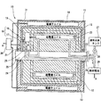
図1に示すように、本実施形態の超電導モータ装置10は、水素と酸素を反応させて発電する燃料電池を搭載した電気自動車の駆動用に用いられるもので、該水素の供給源として搭載された極低温の液体水素(沸点:約−252.8℃)を超電導モータ装置10の超電導コイル15および変換器の冷却用の冷媒として兼用している。
Embodiments of the present invention will be described with reference to the drawings.
As shown in FIG. 1, the
超電導モータ装置10は、ハウジングとなるステータ11に複数の電機子コイル14を周方向に間隔をあけて固定しており、ステータ11内において軸受21を介して設けられた回転駆動軸20と固定されたロータ12に界磁用の超電導コイル15を設けている。
外部の電力供給制御部30からの電力をロータ12の超電導コイル15に供給する手段として、ステータ11とロータ12との間の空間を非接触で電磁誘導により給電する非接触給電手段16が設けられており、非接触給電手段16は、ステータ11側に取り付けられた誘導給電送信部17と、ロータ12側に取り付けられた誘導給電受信部18とを備えている。
誘導給電受信部18で受電される電流は交流であるため、ロータ12側において誘導給電受信部18と超電導コイル15との間に炭化ケイ素(SiC)半導体素子を用いた変換器19を介設し、該交流を直流に変換して超電導コイル15に給電している。
The
As means for supplying power from the external power
Since the current received by the
超電導コイル15は、冷媒導入路22と冷媒導出路24とが連通された冷却空間23の内部に設置されている。冷媒導入路22へは、車載された液体水素タンク27の液体水素をポンプ28を介して供給しており、超電導コイル15との熱交換により昇温気化された水素ガスが冷媒導出路24に排出される。
冷媒導出路24は、調温ユニット25を介して変換器19へと連通されており、調温ユニット25において、後述する変換器19の炭化ケイ素半導体素子が最適動作するための温度である−100℃〜0℃に水素ガスを温度制御してから変換器19へ供給冷却している。
The
The
変換器19を冷却した水素ガスは、変換器19と外部の燃料電池29とを結ぶ冷媒排出路26を通過して燃料電池29へと発電用として供給している。
ロータ12内には、超電導コイル15を収容した冷却空間23と、調温ユニット25、変換器19および誘導給電受信部18とを隔離するように断熱層が設けられている。
ステータ11の外面は電磁シールド材31で囲繞しており、非接触給電手段16で発生する磁界と共に、超電導コイル23および電機子コイル14で発生する磁界も外部に漏れないようにシールドして、車載された周囲の電子機器や各種通信機器等へ悪影響を及ぼさないようしている。
The hydrogen gas that has cooled the
In the
The outer surface of the
燃料電池29で発電された電力は、電力供給制御部30へ供給されるように電線で接続されている。電力供給制御部30は、燃料電池29から電線を介して供給される電力を入力とする一方、誘導給電送信部17および各電機子コイル14へ電線を介して供給する電力を出力としており、各出力のタイミングや電圧等を電子制御している。
The electric power generated by the
次に、超電導モータ装置10の回転原理について説明する。
電力供給制御部30から非接触給電手段16および変換器19を介して超電導コイル15に給電することで、図2に示すように、ロータ12にN極、S極を有する電磁石となる。そして、電力供給制御部30において、ステータ11側の周方向に間隔をあけて配置された4つの電機子コイル14に対して、S1→S2→S3→S4→S1・・と順次、電流を給電することで回転磁界が発生する。この回転磁界は電磁石となったロータ12を引っ張って同期回転させて回転駆動軸20を駆動させる。そして、回転駆動軸20のトルクが電気自動車の車輪の回転動力として伝達される。
Next, the rotation principle of the
By supplying power to the
なお、本実施形態では電機子コイル14を4つ設けているが、周方向に3つ設けて夫々の電機子コイルに三相交流を供給して回転磁界を発生させてもよい。また、超電導コイル15にはビスマス系超電導線材を使用しているが、イットリウム系、タリウム系、ビスマス系の酸化物等のセラミック材を用いてもよい。また、本実施形態では冷媒として液体水素を用いているが、液体窒素を用いても構わない。
In this embodiment, four
以下、変換器19に用いられる炭化ケイ素半導体素子に関する抵抗率と温度との相関関係を表す実験例を図3および図4を用いて説明する。
実験装置は、図3に示すように、冷媒通路41の上面に炭化ケイ素半導体素子42を載置すると共に、炭化ケイ素半導体素子42に熱電対43を当接させており、外部を断熱チャンバー40で覆うことにより内部を真空にしている。
Hereinafter, an experimental example showing the correlation between the resistivity and the temperature related to the silicon carbide semiconductor element used in the
As shown in FIG. 3, the experimental apparatus has a silicon
炭化ケイ素半導体素子42は、4H−SiC型の炭化ケイ素半導体素子42に窒素イオンが1cm3当たり1013〜1017ドーピングされたn型半導体からなる半導体基板を用いている。その炭化ケイ素半導体素子22にDC1Vを印加して電流を計測し温度と抵抗率の関係を調べている。図4に示す実験結果によると、50℃から−130℃にかけて抵抗率が10-1以下と低くなっていると共に、約−60℃近傍で最も抵抗率が低減できることが分かる。つまり、極低温の冷媒を使用して炭化ケイ素半導体素子を冷却することを考慮すると、0℃〜−100℃の範囲に雰囲気温度を設定することで、炭化ケイ素半導体素子を有効に動作させることができる。
The silicon
したがって、上述した超電導モータ装置10においては、冷却空間23で超電導コイル15を冷却することにより気化して冷媒導出路24に排出された水素ガスを、調温ユニット25で0℃〜−100℃に温度調節してから変換器19に送ることで、変換器19を効率良く動作させることができる。
また、超電導コイル15を冷却した後の昇温した水素ガスを変換器19の冷却用の冷媒として流用することで、変換器19専用に別の冷却手段を設ける必要がなくなり、超電導コイル15よりは冷却温度が高くてもよい変換器19の冷却を効率良く且つ低コストで行うことができる。
Therefore, in the
Further, by diverting the heated hydrogen gas after cooling the
10 超電導モータ装置
11 ステータ
12 ロータ
13 断熱層
14 電機子コイル
15 超電導コイル
16 非接触給電手段
17 誘導給電送信部
18 誘導給電受信部
19 変換器
20 回転駆動軸
21 軸受
22 冷媒導入部
23 冷却空間
24 冷媒導出路
25 調温ユニット
26 冷媒排出路
27 液体水素タンク
28 ポンプ
29 燃料電池
30 電力供給制御部
DESCRIPTION OF
Claims (9)
上記超電導コイルは上記ロータ内の冷却空間に配置されており、該冷却空間には外部から冷媒が供給される冷媒導入路と、上記超電導コイルとの熱交換により温度上昇した冷媒が排出される冷媒導出路とが設けられ、該冷媒導出路の昇温した冷媒により上記変換器を冷却する構成としていることを特徴とする超電導モータ装置。 A non-contact power feeding means for performing inductive power feeding between the rotor and the stator is provided, and a converter for converting alternating current to direct current and a superconducting coil are fixed to the rotor. A superconducting motor device that converts alternating current received on the rotor side into direct current by the converter and supplies power to the superconducting coil,
The superconducting coil is disposed in a cooling space in the rotor, and a refrigerant introduction path through which a refrigerant is supplied from the outside to the cooling space, and a refrigerant from which the refrigerant whose temperature has been raised by heat exchange with the superconducting coil is discharged. A superconducting motor device, characterized in that a lead-out path is provided and the converter is cooled by the refrigerant whose temperature has risen in the refrigerant lead-out path.
上記超電導コイルに給電して励磁することで上記ロータ側を電磁石とし、上記複数の電機子コイルの各々に順次給電することで回転磁界を発生させて上記ロータを回転駆動している請求項1に記載の超電導モータ装置。 The superconducting coil fixed to the rotor is for field use, and a plurality of armature coils are fixed to the stator side at intervals in the circumferential direction.
2. The rotor according to claim 1, wherein the rotor side is electromagnetized by feeding and exciting the superconducting coil, and the rotor is rotated by generating a rotating magnetic field by sequentially feeding each of the plurality of armature coils. The superconducting motor device described.
上記冷媒として上記液体水素タンクの液体水素を用いており、上記冷媒導入路、上記冷媒空間、上記冷媒導出路および上記変換器を通過して気化された水素ガスを上記燃料電池に供給して発電し、該電力を上記超電導コイルおよび上記電機子コイルに給電している請求項1乃至請求項8のいずれか1項に記載の超電導モータ装置。 It is mounted on an electric vehicle that generates electricity by reacting hydrogen stored in a liquid hydrogen tank with oxygen by a fuel cell,
Liquid hydrogen in the liquid hydrogen tank is used as the refrigerant, and hydrogen gas evaporated through the refrigerant introduction path, the refrigerant space, the refrigerant outlet path, and the converter is supplied to the fuel cell for power generation. The superconducting motor device according to any one of claims 1 to 8, wherein the electric power is supplied to the superconducting coil and the armature coil.
Priority Applications (1)
| Application Number | Priority Date | Filing Date | Title |
|---|---|---|---|
| JP2004029898A JP4419588B2 (en) | 2004-02-05 | 2004-02-05 | Superconducting motor device |
Applications Claiming Priority (1)
| Application Number | Priority Date | Filing Date | Title |
|---|---|---|---|
| JP2004029898A JP4419588B2 (en) | 2004-02-05 | 2004-02-05 | Superconducting motor device |
Publications (3)
| Publication Number | Publication Date |
|---|---|
| JP2005224022A JP2005224022A (en) | 2005-08-18 |
| JP2005224022A5 JP2005224022A5 (en) | 2006-09-28 |
| JP4419588B2 true JP4419588B2 (en) | 2010-02-24 |
Family
ID=34999231
Family Applications (1)
| Application Number | Title | Priority Date | Filing Date |
|---|---|---|---|
| JP2004029898A Expired - Fee Related JP4419588B2 (en) | 2004-02-05 | 2004-02-05 | Superconducting motor device |
Country Status (1)
| Country | Link |
|---|---|
| JP (1) | JP4419588B2 (en) |
Families Citing this family (9)
| Publication number | Priority date | Publication date | Assignee | Title |
|---|---|---|---|---|
| US7843094B2 (en) * | 2009-04-09 | 2010-11-30 | Goodzeit Carl L | Dual armature motor/generator with flux linkage between dual armatures and a superconducting field coil |
| US8084909B2 (en) | 2009-04-09 | 2011-12-27 | Goodzeit Carl L | Dual armature motor/generator with flux linkage |
| JP5655603B2 (en) * | 2011-02-04 | 2015-01-21 | オムロン株式会社 | Non-contact rotary power transmission device |
| KR200473549Y1 (en) | 2012-12-28 | 2014-07-09 | 두산엔진주식회사 | Super conducting electric power generation system |
| KR102087172B1 (en) * | 2013-07-03 | 2020-03-10 | 대우조선해양 주식회사 | Liquid oxygen cooling system using superconductor motor cycle |
| DE102015117296A1 (en) | 2015-10-09 | 2017-04-13 | Oswald Elektromotoren Gmbh | Electric machine |
| WO2017094420A1 (en) * | 2015-12-04 | 2017-06-08 | 日本精工株式会社 | Rolling bearing unit for drive wheel support |
| WO2019220723A1 (en) * | 2018-05-16 | 2019-11-21 | 株式会社日立製作所 | Superconducting rotary machine |
| KR102449789B1 (en) * | 2020-07-28 | 2022-10-04 | 한국기계연구원 | Superconduction motor driving system using liquid hydrogen |
-
2004
- 2004-02-05 JP JP2004029898A patent/JP4419588B2/en not_active Expired - Fee Related
Also Published As
| Publication number | Publication date |
|---|---|
| JP2005224022A (en) | 2005-08-18 |
Similar Documents
| Publication | Publication Date | Title |
|---|---|---|
| US9143019B2 (en) | Rotating electric machine | |
| JP4419588B2 (en) | Superconducting motor device | |
| CN102782331B (en) | Turbo molecular pump device | |
| KR101546175B1 (en) | Pole shoe | |
| EP2141786B1 (en) | Rotary electric machine for vehicles | |
| CN109874370B (en) | System having an electric machine with a cryogenic component and method for operating the system | |
| US20040100154A1 (en) | Concentrated winding electric motor having optimized winding cooling and slot fill | |
| JP5043955B2 (en) | Superconducting synchronous motor | |
| US20210344256A1 (en) | Rotor and machine having superconducting permanent magnets | |
| JP4501449B2 (en) | Cooling device for superconducting motor | |
| JP2007060747A (en) | Superconducting motor and vehicle equipped with that motor | |
| JP2005269868A (en) | Superconductive motor device and movable body with use of superconductive motor device | |
| CA2384481C (en) | High temperature superconducting rotor power leads | |
| JP2007325341A (en) | Motor and generator | |
| JP2006081379A (en) | Motor unit mounted on vehicle | |
| JP2005237175A (en) | Motor and electric movable body with motor | |
| JP2000114027A (en) | Superconducting coil device | |
| JP2006149007A (en) | Stator yoke and radial gap type motor | |
| JP3832472B2 (en) | Hybrid car | |
| JP2019030153A (en) | Superconducting rotary machine | |
| JP2003100521A (en) | Stationary induction apparatus | |
| JP2007037341A (en) | Cooling structure of superconducting apparatus | |
| JP2009033918A (en) | Superconducting motor, and cooling system for superconducting motor | |
| JP7014635B2 (en) | Inverter unit and motor assembly | |
| US20040124724A1 (en) | AC generator for vehicle having rectifying unit |
Legal Events
| Date | Code | Title | Description |
|---|---|---|---|
| A521 | Request for written amendment filed |
Free format text: JAPANESE INTERMEDIATE CODE: A523 Effective date: 20060811 |
|
| A621 | Written request for application examination |
Free format text: JAPANESE INTERMEDIATE CODE: A621 Effective date: 20060811 |
|
| TRDD | Decision of grant or rejection written | ||
| A01 | Written decision to grant a patent or to grant a registration (utility model) |
Free format text: JAPANESE INTERMEDIATE CODE: A01 Effective date: 20091110 |
|
| A01 | Written decision to grant a patent or to grant a registration (utility model) |
Free format text: JAPANESE INTERMEDIATE CODE: A01 |
|
| A61 | First payment of annual fees (during grant procedure) |
Free format text: JAPANESE INTERMEDIATE CODE: A61 Effective date: 20091123 |
|
| FPAY | Renewal fee payment (event date is renewal date of database) |
Free format text: PAYMENT UNTIL: 20121211 Year of fee payment: 3 |
|
| R150 | Certificate of patent or registration of utility model |
Free format text: JAPANESE INTERMEDIATE CODE: R150 |
|
| LAPS | Cancellation because of no payment of annual fees |