JP7014635B2 - Inverter unit and motor assembly - Google Patents
Inverter unit and motor assembly Download PDFInfo
- Publication number
- JP7014635B2 JP7014635B2 JP2018029369A JP2018029369A JP7014635B2 JP 7014635 B2 JP7014635 B2 JP 7014635B2 JP 2018029369 A JP2018029369 A JP 2018029369A JP 2018029369 A JP2018029369 A JP 2018029369A JP 7014635 B2 JP7014635 B2 JP 7014635B2
- Authority
- JP
- Japan
- Prior art keywords
- electrolytic capacitor
- inverter
- thermoelectric conversion
- conversion element
- mounting member
- Prior art date
- Legal status (The legal status is an assumption and is not a legal conclusion. Google has not performed a legal analysis and makes no representation as to the accuracy of the status listed.)
- Active
Links
Images






Landscapes
- Motor Or Generator Cooling System (AREA)
- Inverter Devices (AREA)
Description
本発明は、インバータユニットおよび該インバータユニットを備えた電動機組立体に関するものである。 The present invention relates to an inverter unit and an electric motor assembly including the inverter unit.
モータの回転速度を制御するインバータが知られている。インバータは、パワー素子(例えば、IGBT:Insulated gate bipolar transistor)および電解コンデンサなどの多数の要素から構成されている。 Inverters that control the rotational speed of motors are known. The inverter is composed of many elements such as a power element (for example, an IGBT: Insulated gate bipolar transistor) and an electrolytic capacitor.
モータのインバータ駆動の際に動作するパワー素子およびパワー素子とともに動作する電解コンデンサは発熱源であるため、インバータが駆動されると、パワー素子の温度および電解コンデンサの温度は高くなる。一般的に、電解コンデンサには、電解コンデンサの温度が10℃低下すると、電解コンデンサの寿命が2倍となる法則(10℃2倍則)、所謂、アレニウスの法則が適用される。したがって、電解コンデンサの温度が低下されれば、電解コンデンサの長寿命が期待される。 Since the power element that operates when driving the inverter of the motor and the electrolytic capacitor that operates together with the power element are heat sources, the temperature of the power element and the temperature of the electrolytic capacitor become high when the inverter is driven. Generally, the so-called Arrhenius law, which doubles the life of an electrolytic capacitor when the temperature of the electrolytic capacitor drops by 10 ° C. (10 ° C. double rule), is applied to the electrolytic capacitor. Therefore, if the temperature of the electrolytic capacitor is lowered, the life of the electrolytic capacitor is expected to be long.
そこで、本発明は、電解コンデンサの長寿命化を図ることができるインバータユニットを提供することを目的とする。本発明は、該インバータユニットを備えた電動機組立体を提供することを目的とする。 Therefore, an object of the present invention is to provide an inverter unit capable of extending the life of an electrolytic capacitor. It is an object of the present invention to provide a motor assembly equipped with the inverter unit.
一態様は、電解コンデンサを含むインバータ要素と、前記インバータ要素が実装された基板と、前記基板が取り付けられたインバータ取り付け部材と、前記電解コンデンサと前記インバータ取り付け部材の内面との間に配置された熱電変換素子と、前記熱電変換素子に電気的に接続され、前記熱電変換素子に電力を供給する電源装置と、前記電源装置に電気的に接続され、前記電源装置の動作を制御する制御装置とを備え、前記熱電変換素子は、前記電解コンデンサに接触する一方の面と、該一方の面の反対側に位置し、前記インバータ取り付け部材の内面に接触する反対側の面とを有しており、前記制御装置は、前記電源装置から前記熱電変換素子に電力を供給させて、前記電解コンデンサの熱を前記インバータ取り付け部材に伝達させることを特徴とするインバータユニットである。 One aspect is arranged between an inverter element including an electrolytic capacitor, a board on which the inverter element is mounted, an inverter mounting member to which the board is mounted, and an inner surface of the electrolytic capacitor and the inverter mounting member. A thermoelectric conversion element, a power supply device electrically connected to the thermoelectric conversion element to supply electric power to the thermoelectric conversion element, and a control device electrically connected to the power supply device to control the operation of the power supply device. The thermoelectric conversion element has one surface in contact with the electrolytic capacitor and the opposite surface located on the opposite side of the one surface and in contact with the inner surface of the inverter mounting member. The control device is an inverter unit characterized in that electric power is supplied from the power supply device to the thermoelectric conversion element and the heat of the electrolytic capacitor is transferred to the inverter mounting member.
好ましい態様は、前記インバータユニットは、前記電解コンデンサに隣接して配置された温度センサを備えており、前記制御装置は、前記温度センサによって検出された温度を監視し、前記温度が冷却開始しきい値まで上昇した場合、前記電源装置から前記熱電変換素子に電力を供給させて、前記電解コンデンサの熱を前記インバータ取り付け部材に伝達させることを特徴とする。
好ましい態様は、前記インバータユニットは、前記熱電変換素子に流れる電流の方向を、前記電解コンデンサの熱を前記インバータ取り付け部材に伝達させる第1電流方向と前記インバータ取り付け部材の熱を前記電解コンデンサに伝達させる第2電流方向との間で切り替えるスイッチ部を備えており、前記制御装置は、前記温度が前記冷却開始しきい値まで上昇した場合、前記スイッチ部を動作させて、前記熱電変換素子に流れる電流の方向を前記第1電流方向に切り替え、前記温度が前記冷却開始しきい値よりも小さな加熱開始しきい値以下である場合、前記スイッチ部を動作させて、前記熱電変換素子に流れる電流の方向を前記第2電流方向に切り替えることを特徴とする。
好ましい態様は、前記基板は、前記インバータ取り付け部材の内面と平行に配置されており、かつ前記電解コンデンサが挿入可能な大きさを有する挿入孔を有しており、前記電解コンデンサは、前記電解コンデンサの底面が前記熱電変換素子を介して前記インバータ取り付け部材の内面と対向するように、前記挿入孔に挿入されていることを特徴とする。
In a preferred embodiment, the inverter unit includes a temperature sensor arranged adjacent to the electrolytic capacitor, the control device monitors the temperature detected by the temperature sensor, and the temperature starts to cool. When the temperature rises to the value, the power supply device supplies electric power to the thermoelectric conversion element, and the heat of the electrolytic capacitor is transferred to the inverter mounting member.
In a preferred embodiment, the inverter unit transfers the direction of the current flowing through the thermoelectric conversion element to the electrolytic capacitor, the first current direction for transmitting the heat of the electrolytic capacitor to the inverter mounting member, and the heat of the inverter mounting member to the electrolytic capacitor. A switch unit for switching between the current direction and the second current direction is provided, and when the temperature rises to the cooling start threshold value, the control device operates the switch unit and flows to the thermoelectric conversion element. When the direction of the current is switched to the first current direction and the temperature is equal to or less than the heating start threshold value smaller than the cooling start threshold value, the switch unit is operated to obtain the current flowing through the thermoelectric conversion element. It is characterized in that the direction is switched to the second current direction.
In a preferred embodiment, the substrate is arranged parallel to the inner surface of the inverter mounting member and has an insertion hole having a size into which the electrolytic capacitor can be inserted, and the electrolytic capacitor is the electrolytic capacitor. The bottom surface of the capacitor is inserted into the insertion hole so as to face the inner surface of the inverter mounting member via the thermoelectric conversion element.
他の態様は、電解コンデンサを含むインバータ要素と、前記インバータ要素が実装された基板と、前記基板が取り付けられたインバータ取り付け部材と、前記インバータ取り付け部材の内面に接触し、前記電解コンデンサを収容するコンデンサケースと、前記コンデンサケースの内面に貼り付けられた熱電変換素子と、前記熱電変換素子に電気的に接続され、前記熱電変換素子に電力を供給する電源装置と、前記電源装置に電気的に接続され、前記電源装置の動作を制御する制御装置とを備え、前記熱電変換素子は、前記電解コンデンサに接触する一方の面と、該一方の面の反対側に位置し、前記コンデンサケースの内面に接触する反対側の面とを有しており、前記制御装置は、前記電源装置から前記熱電変換素子に電力を供給させて、前記電解コンデンサの熱を前記コンデンサケースに伝達させることを特徴とするインバータユニットである。 Another aspect is to contact the inverter element including the electrolytic capacitor, the substrate on which the inverter element is mounted, the inverter mounting member to which the substrate is mounted, and the inner surface of the inverter mounting member to accommodate the electrolytic capacitor. A capacitor case, a thermoelectric conversion element attached to the inner surface of the capacitor case, a power supply device electrically connected to the thermoelectric conversion element to supply power to the thermoelectric conversion element, and electrically to the power supply device. It comprises a control device that is connected and controls the operation of the power supply device, the thermoelectric conversion element is located on one surface in contact with the electrolytic capacitor and on the opposite side of the one surface, and is an inner surface of the capacitor case. The control device has a surface on the opposite side in contact with the capacitor, and the control device is characterized in that power is supplied from the power supply device to the thermoelectric conversion element and the heat of the electrolytic capacitor is transferred to the capacitor case. It is an inverter unit.
好ましい態様は、前記インバータユニットは、前記コンデンサケースに隣接して配置された温度センサを備えており、前記制御装置は、前記温度センサによって検出された温度を監視し、前記温度が冷却開始しきい値まで上昇した場合、前記電源装置から前記熱電変換素子に電力を供給させて、前記電解コンデンサの熱を前記コンデンサケースに伝達させることを特徴とする。
好ましい態様は、前記インバータユニットは、前記熱電変換素子に流れる電流の方向を、前記電解コンデンサの熱を前記コンデンサケースに伝達させる第1電流方向と前記コンデンサケースの熱を前記電解コンデンサに伝達させる第2電流方向との間で切り替えるスイッチ部を備えており、前記制御装置は、前記温度が前記冷却開始しきい値まで上昇した場合、前記スイッチ部を動作させて、前記熱電変換素子に流れる電流の方向を前記第1電流方向に切り替え、前記温度が前記冷却開始しきい値よりも小さな加熱開始しきい値以下である場合、前記スイッチ部を動作させて、前記熱電変換素子に流れる電流の方向を前記第2電流方向に切り替えることを特徴とする。
好ましい態様は、前記基板は、前記インバータ取り付け部材の内面と平行に配置されており、かつ前記コンデンサケースが挿入可能な大きさを有する挿入孔を有しており、前記コンデンサケースは、前記電解コンデンサの底面が前記コンデンサケースを介して前記インバータ取り付け部材の内面と対向するように、前記挿入孔に挿入されていることを特徴とする。
In a preferred embodiment, the inverter unit includes a temperature sensor arranged adjacent to the condenser case, the control device monitors the temperature detected by the temperature sensor, and the temperature starts to cool. When the temperature rises to a value, the power supply device supplies power to the thermoelectric conversion element, and the heat of the electrolytic capacitor is transferred to the capacitor case.
In a preferred embodiment, the inverter unit has a first current direction for transferring the direction of the current flowing through the thermoelectric conversion element to the capacitor case and a first current direction for transferring the heat of the capacitor case to the electrolytic capacitor. A switch unit for switching between two current directions is provided, and the control device operates the switch unit when the temperature rises to the cooling start threshold value, and the current flowing through the thermoelectric conversion element. When the direction is switched to the first current direction and the temperature is equal to or less than the heating start threshold value smaller than the cooling start threshold value, the switch unit is operated to change the direction of the current flowing through the thermoelectric conversion element. It is characterized by switching in the second current direction.
In a preferred embodiment, the substrate is arranged parallel to the inner surface of the inverter mounting member and has an insertion hole having a size into which the capacitor case can be inserted, and the capacitor case is the electrolytic capacitor. The bottom surface of the inverter is inserted into the insertion hole so as to face the inner surface of the inverter mounting member via the capacitor case.
さらに他の態様は、駆動軸と、前記駆動軸を回転させる回転子および固定子を備えるモータと、前記モータを収容するモータケーシングと、前記モータの回転速度を制御するためのインバータユニットとを備え、前記インバータユニットは、電解コンデンサを含むインバータ要素と、前記インバータ要素が実装された基板と、前記モータケーシングに接続されたインバータフレームの開口端を閉じ、かつ前記基板が取り付けられるインバータ取り付け部材と、前記電解コンデンサと前記インバータ取り付け部材の内面との間に配置された熱電変換素子と、前記熱電変換素子に電気的に接続され、前記熱電変換素子に電力を供給する電源装置と、前記電源装置に電気的に接続され、前記電源装置の動作を制御する制御装置とを備えており、前記熱電変換素子は、前記電解コンデンサに接触する一方の面と、該一方の面の反対側に位置し、前記インバータ取り付け部材の内面に接触する反対側の面とを有しており、前記制御装置は、前記電源装置から前記熱電変換素子に電力を供給させて、前記電解コンデンサの熱を前記インバータ取り付け部材に伝達させることを特徴とする電動機組立体である。 Yet another embodiment includes a drive shaft, a motor including a rotor and a stator for rotating the drive shaft, a motor casing accommodating the motor, and an inverter unit for controlling the rotation speed of the motor. The inverter unit includes an inverter element including an electrolytic capacitor, a board on which the inverter element is mounted, an inverter mounting member that closes the open end of an inverter frame connected to the motor casing, and to which the board is mounted. The thermoelectric conversion element arranged between the electrolytic capacitor and the inner surface of the inverter mounting member, the power supply device electrically connected to the thermoelectric conversion element and supplying power to the thermoelectric conversion element, and the power supply device. It is electrically connected and includes a control device that controls the operation of the power supply device, and the thermoelectric conversion element is located on one surface in contact with the electrolytic capacitor and on the opposite side of the one surface. It has a surface on the opposite side that contacts the inner surface of the inverter mounting member, and the control device supplies power from the power supply device to the thermoelectric conversion element and transfers the heat of the electrolytic capacitor to the inverter mounting member. It is an electric motor assembly characterized by being transmitted to an inverter.
さらに他の態様は、駆動軸と、前記駆動軸を回転させる回転子および固定子を備えるモータと、前記モータを収容するモータケーシングと、前記モータの回転速度を制御するためのインバータユニットとを備え、前記インバータユニットは、電解コンデンサを含むインバータ要素と、前記インバータ要素が実装された基板と、前記モータケーシングに接続されたインバータフレームの開口端を閉じ、かつ前記基板が取り付けられるインバータ取り付け部材と、前記インバータ取り付け部材の内面に接触し、前記電解コンデンサを収容するコンデンサケースと、前記コンデンサケースの内面に貼り付けられた熱電変換素子と、前記熱電変換素子に電気的に接続され、前記熱電変換素子に電力を供給する電源装置と、前記電源装置に電気的に接続され、前記電源装置の動作を制御する制御装置とを備えており、前記熱電変換素子は、前記電解コンデンサに接触する一方の面と、該一方の面の反対側に位置し、前記コンデンサケースの内面に接触する反対側の面とを有しており、前記制御装置は、前記電源装置から前記熱電変換素子に電力を供給させて、前記電解コンデンサの熱を前記コンデンサケースに伝達させることを特徴とする電動機組立体である。 Yet another embodiment includes a drive shaft, a motor including a rotor and a stator for rotating the drive shaft, a motor casing accommodating the motor, and an inverter unit for controlling the rotation speed of the motor. The inverter unit includes an inverter element including an electrolytic capacitor, a board on which the inverter element is mounted, an inverter mounting member that closes the open end of an inverter frame connected to the motor casing, and to which the board is mounted. A capacitor case that comes into contact with the inner surface of the inverter mounting member and accommodates the electrolytic capacitor, a thermoelectric conversion element attached to the inner surface of the capacitor case, and the thermoelectric conversion element that is electrically connected to the thermoelectric conversion element. The thermoelectric conversion element includes a power supply device that supplies power to the power supply device and a control device that is electrically connected to the power supply device and controls the operation of the power supply device. And, which is located on the opposite side of the one surface and has the opposite surface in contact with the inner surface of the condenser case, the control device causes the power supply device to supply power to the thermoelectric conversion element. The electric motor assembly is characterized in that the heat of the electrolytic capacitor is transferred to the capacitor case.
制御装置は、電源装置から熱電変換素子に電力を供給させて、電解コンデンサの熱をインバータ取り付け部材に伝達させる。このようにして、制御装置は、熱電変換素子を介して電解コンデンサを冷却することができるため、アレニウスの法則によって電解コンデンサの長寿命化が実現される。 The control device supplies electric power from the power supply device to the thermoelectric conversion element, and transfers the heat of the electrolytic capacitor to the inverter mounting member. In this way, the control device can cool the electrolytic capacitor via the thermoelectric conversion element, so that the life of the electrolytic capacitor can be extended according to the Arrhenius law.
以下、本発明の実施形態について図面を参照して説明する。なお、以下で説明する図面において、同一又は相当する構成要素には、同一の符号を付して重複した説明を省略する。以下で説明する複数の実施形態において、特に説明しない一実施形態の構成は、他の実施形態と同じであるので、その重複する説明を省略する。 Hereinafter, embodiments of the present invention will be described with reference to the drawings. In the drawings described below, the same or corresponding components are designated by the same reference numerals and duplicated description will be omitted. In the plurality of embodiments described below, the configuration of one embodiment not particularly described is the same as that of the other embodiments, and therefore the duplicated description thereof will be omitted.
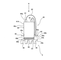
図1はインバータユニット3の一実施形態を示す図である。インバータユニット3は、太陽光パネルを用いた太陽光発電システム、またはポンプなどの回転機械を回転させる電動機組立体などの機械装置に適用することができる。後述する実施形態では、インバータユニット3を備えた電動機組立体1の構造について説明する。
FIG. 1 is a diagram showing an embodiment of the
図1に示すように、インバータユニット3は、図示しない整流器によって整流された電力を平滑化するとともに静電容量により電荷を蓄積する電解コンデンサ41Aを含むインバータ要素41と、インバータ要素41が実装された基板42と、基板42に隣接するインバータ取り付け部材23とを備えている。インバータ要素41は、電解コンデンサ41Aの他、IGBTなどのパワー素子41Bおよびパワー素子41Bを駆動するドライバ回路(図示しない)などの電子部品を備えている。インバータ要素41および基板42はインバータ20を構成している。以下、インバータ要素41および基板42を総称してインバータ20と呼ぶことがある。インバータ20はインバータユニット3が適用される機械装置を動作させるために必要な構成要素である。なお、図1では、単一の電解コンデンサ41Aおよび単一のパワー素子41Bが描かれているが、インバータユニット3は、複数の電解コンデンサ41Aおよび複数のパワー素子41Bを備えてもよい。
As shown in FIG. 1, the
基板42はインバータ取り付け部材23に取り付けられている。インバータ20はインバータ取り付け部材23上に載置されており、基板42はインバータ取り付け部材23の内面23aと平行に配置されている。インバータ取り付け部材23は、その内面23aとは反対側に位置する外面23bを有しており、インバータ取り付け部材23の外面23bには、複数のフィン36が形成されている。これらフィン36は、インバータ取り付け部材23の外面23bから外側に向かって延びている。
The
インバータ取り付け部材23の形状は図1に示す実施形態には限定されない。インバータ取り付け部材23の形状はインバータユニット3が適用される機械装置の構造に応じて変更されてもよい。
The shape of the
インバータ取り付け部材23(およびフィン36)は、ヒートシンクとしての役割を果たすため、比較的高い放熱性能を有する材料(例えば、アルミニウム(Al)などの熱伝導性に優れた金属)から、基本的に構成されている。基板42は、インバータ要素41が実装される実装面42aと、実装面42aの反対側に位置する裏面42bとを有している。パワー素子41Bは、基板42の裏面42b側、すなわち、基板42とインバータ取り付け部材23の内面23aとの間に配置されている。
Since the inverter mounting member 23 (and the fin 36) serves as a heat sink, it is basically composed of a material having relatively high heat dissipation performance (for example, a metal having excellent thermal conductivity such as aluminum (Al)). Has been done. The
パワー素子41Bは、絶対最大定格温度としてのジャンクション温度(例えば、150℃)以下という条件下で使用される必要がある。本実施形態では、発熱源であるパワー素子41Bはインバータ取り付け部材23の内面23aに接触しており、ヒートシンクとしてのインバータ取り付け部材23はパワー素子41Bの熱を吸収するために十分な大きさを有している。したがって、パワー素子41Bから発せられた熱は、インバータ取り付け部材23およびフィン36を通じて外部に放出され、結果として、パワー素子41Bは冷却される。したがって、パワー素子41Bは、ジャンクション温度以下の条件下で使用される。
The
電解コンデンサ41Aもパワー素子41Bと同様に発熱源であり、電解コンデンサ41Aは、リプル電流および等価直列抵抗による損失などの影響により発熱する。上述したように、電解コンデンサ41Aには、電解コンデンサ41Aの温度が10℃低下すると、電解コンデンサ41Aの寿命が2倍となる法則(所謂、アレニウスの法則)が適用される。したがって、電解コンデンサ41Aの温度が低下されれば、電解コンデンサ41Aの長寿命が実現される。以下、電解コンデンサ41Aの長寿命化を図ることができるインバータユニット3の構成について説明する。
The
インバータユニット3は、電解コンデンサ41Aとインバータ取り付け部材23の内面23aとの間に配置された熱電変換素子50と、熱電変換素子50に電気的に接続され、熱電変換素子50に電力を供給する電源装置51と、電源装置51に電気的に接続され、電源装置51の動作を制御する制御装置55とを備えている。
The
図2は電解コンデンサ41Aおよび熱電変換素子50の拡大図である。図2に示すように、熱電変換素子50は、電解コンデンサ41Aに接触する一方の面(電解コンデンサ側接触面)50aと、一方の面50aの反対側に位置し、インバータ取り付け部材23の内面23aに接触する反対側の面(インバータ取り付け部材側接触面)50bとを有している。
FIG. 2 is an enlarged view of the
熱電変換素子50は、電源装置51から供給された電力によってペルチェ効果を発揮する公知のペルチェ素子であり、P型半導体およびN型半導体が交互に配列された板状の構造を有している。熱電変換素子50は、電源装置51から供給された電力によって、熱電変換素子50の両面(すなわち、一方の面50aおよび反対側の面50b)の間に熱流が発生する構造を有している。
The
一実施形態では、熱電変換素子50は、電源装置51から供給された電力により発生したスピン流を熱流に変換する構造を有してもよい。このような構造を有する熱電変換素子50は、スピン変換技術が用いられた素子であり、特許文献1(特開2016-9838号公報)に記載された薄膜形状を有するテープ状の熱電変換素子と同様の熱電変換構造を有している。
In one embodiment, the
スピン変換とは、角運動量保存の法則に基づく物理量(例えば、熱、電気など)の相互変換の総称である。スピン流(spin current)は電子のスピン角運動量の流れである。電流とスピン流と熱流との間には相互作用が存在する。したがって、熱電変換素子50に電力が供給されると、すなわち、電流が流れると、熱電変換素子50には、スピン流が発生する。このような現象は、スピンホール効果(spin Hall effect)と呼ばれる。熱電変換素子50にスピン流が流れると、熱電変換素子50には、熱流が発生する。このような現象は、スピンペルチェ効果(spin Peltier effect)と呼ばれる。
Spin conversion is a general term for mutual conversion of physical quantities (for example, heat, electricity, etc.) based on the law of conservation of angular momentum. Spin current is the flow of electron spin angular momentum. There is an interaction between the current, the spin current, and the heat current. Therefore, when electric power is supplied to the
スピンペルチェ効果とは逆に、熱電変換素子50に熱流が流れると、熱電変換素子50には、スピン流が発生する。このような現象は、スピンゼーベック効果(spin Seebeck effect)と呼ばれる。スピンホール効果とは逆に、熱電変換素子50にスピン流が流れると、熱電変換素子50には、起電力が発生する。このような現象は、逆スピンホール効果(inverse spin Hall effect)と呼ばれる。本実施形態における熱電変換素子50は、スピンホール効果およびスピンペルチェ効果を利用することにより、スピンを介して電力を熱流に変換することができる。
Contrary to the spin Pelche effect, when a heat flow flows through the
図2に示すように、電解コンデンサ41Aは、図示しないコンデンサ素子が内部に収容された本体部60と、本体部60の一端に接続された2つの端子61とを備えている。2つの端子61のそれぞれには、2つのリード線62のそれぞれが接続されており、これらリード線62は、基板42の実装面42aに接続されている。本実施形態では、電解コンデンサ41Aおよび基板42はインバータ取り付け部材23上に載置されており、端子61は基板42の実装面42aの直ぐ上方に位置している。したがって、端子61と基板42の実装面42aとの間の距離は比較的短い。このような構成により、端子61と基板42の実装面42aとを接続するリード線62の長さを比較的短くすることができる。
As shown in FIG. 2, the
本体部60は、端子61が接続された端子面60aと、端子面60aの反対側に位置する底面60bと、端子面60aと底面60bとの間に延びる外周面60cとを有している。熱電変換素子50の一方の面50a(電解コンデンサ側接触面)は電解コンデンサ41Aの本体部60の底面60bに接触している。
The
図3(a)は図2のA線方向から見た図(電解コンデンサが配置されていない状態)であり、図3(b)は図2のA線方向から見た図(電解コンデンサが配置された状態)である。本実施形態では、電解コンデンサ41Aの本体部60は円柱形状を有しており、熱電変換素子50の幅方向の大きさ(より具体的には、熱電変換素子50の直径)は電解コンデンサ41Aの本体部60の幅方向の大きさ(より具体的には、外周面60cの直径)と同じである。熱電変換素子50の幅方向とは、熱電変換素子50の厚さ方向とは垂直な方向を意味する。本体部60の幅方向とは、本体部60の高さ方向とは垂直な方向を意味する。このように、本実施形態では、熱電変換素子50は電解コンデンサ41Aの外形形状に合わせた形状を有している。
FIG. 3A is a view seen from the direction of line A in FIG. 2 (state in which the electrolytic capacitor is not arranged), and FIG. 3B is a view seen from the direction of line A in FIG. 2 (electrolytic capacitor is arranged). It is in the state of being done). In the present embodiment, the
図2に示すように、電解コンデンサ41Aは、その本体部60の底面60bが熱電変換素子50を介してインバータ取り付け部材23の内面23aに対向するように配置されている。言い換えれば、電解コンデンサ41Aは、熱電変換素子50を介してインバータ取り付け部材23上に載置されている。したがって、熱電変換素子50は、電解コンデンサ41Aの底面60bおよびインバータ取り付け部材23の内面23aの両方に接触する。
As shown in FIG. 2, the
図2および図3(図3(a)および図3(b))に示すように、基板42は、電解コンデンサ41Aが挿入可能な大きさを有する挿入孔42cを有しており、挿入孔42cの直径は電解コンデンサ41Aの本体部60の外周面60cの直径よりも大きい。図3では、挿入孔42cの大きさは誇張して描かれている。挿入孔42cは基板42の実装面42aおよび裏面42bの両方で開口する貫通孔である。挿入孔42cの数は電解コンデンサ41Aの数に対応しており、本実施形態では、単一の電解コンデンサ41Aに対して単一の挿入孔42cが設けられている。一実施形態では、挿入孔42cを設ける代わりに、基板42の外周面から内側に向かって延びる切り欠きが設けられてもよい。基板42の外周面は、基板42の実装面42aと裏面42bとの間に延びる基板42の最も外側の面である。
As shown in FIGS. 2 and 3 (FIGS. 3A and 3B), the
本実施形態では、電解コンデンサ41Aは、電解コンデンサ41Aの底面60bがインバータ取り付け部材23の内面23aと対向するように、挿入孔42cに挿入されている。電解コンデンサ41Aを挿入孔42cに挿入することにより、電解コンデンサ41Aは直立姿勢を維持することができる。電解コンデンサ41Aは、電解コンデンサ41Aの外周面60cに取り付けられた電解コンデンサ固定用バンド(図示しない)を用いてインバータ取り付け部材23の内面23aに固定されてもよい。
In the present embodiment, the
インバータ取り付け部材23が電解コンデンサ41Aおよびパワー素子41Bを含むインバータ要素41の全体を冷却するための十分な大きさを有している場合、インバータ取り付け部材23の大きさは、インバータユニット3が適用される機械装置の全体の大きさに影響を与えてしまう。つまり、機械装置の全体の大きさはインバータ取り付け部材23の大きさに応じて決定される場合があるため、インバータ取り付け部材23の大きさを大きくすれば、機械装置の全体の大きさも大きくなってしまう。
When the
本実施形態では、熱電変換素子50は電解コンデンサ41Aとインバータ取り付け部材23との間に介在しており、インバータ取り付け部材23と基板42との間の隙間に配置されている。電源装置51は制御装置55の指令に基づいて熱電変換素子50に電力を供給し、熱電変換素子50は、そのペルチェ効果により電解コンデンサ41Aの熱をインバータ取り付け部材23に伝達させる。結果として、電解コンデンサ41Aは冷却される。
In the present embodiment, the
本実施形態によれば、熱電変換素子50は、そのペルチェ効果により電解コンデンサ41Aをインバータ取り付け部材23に積極的に放熱することができるため、インバータ取り付け部材23の大きさはパワー素子41Bを冷却するために十分な大きさに抑えられる。電解コンデンサ41Aの放熱は熱電変換素子50によって行われるため、インバータユニット3の省スペース化が実現される。
According to the present embodiment, the
制御装置55は、熱電変換素子50を介して電解コンデンサ41Aを冷却することができるため、アレニウスの法則によって電解コンデンサ41Aの長寿命化を図ることができる。電解コンデンサ41Aの寿命が延びれば、インバータユニット3のメンテナンスの頻度を低減することができ、インバータユニット3のメンテナンスフリーを実現することも可能である。さらに、電解コンデンサ41Aの寿命を延ばすことにより、電解コンデンサ41Aの交換に要するコストを低減することができる。
Since the
図1に示すように、インバータユニット3は、電解コンデンサ41Aの温度を検出する温度センサ70をさらに備えてもよい。図1に示す実施形態では、温度センサ70は、基板42の実装面42a上に配置されているが、電解コンデンサ41Aに直接取り付けられてもよい。電解コンデンサ41Aに隣接して配置された温度センサ70は制御装置55に電気的に接続されており、温度センサ70によって検出された温度は制御装置55に送られる。
As shown in FIG. 1, the
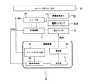
図4は制御装置55を含むインバータユニット3の制御システムの一実施形態を示す図である。図4に示すように、制御装置55は、温度センサ70によって検出された温度、すなわち、電解コンデンサ41Aの温度(より具体的には、電解コンデンサ41Aの周囲の温度)を監視する監視部30と、上記温度と所定のしきい値(冷却開始しきい値)とを比較して、上記温度が冷却開始しきい値まで上昇したか否かを判定する判定部31とを備えている。
FIG. 4 is a diagram showing an embodiment of a control system of the
冷却開始しきい値は、電解コンデンサ41Aの冷却を開始すべき温度の値であり、制御装置55の記憶部(図示しない)に記憶されている。一実施形態では、冷却開始しきい値は、アレニウスの法則(電解コンデンサ41Aの温度と電解コンデンサ41Aの推定寿命との間の相関関係)に基づいて、電解コンデンサ41Aの長寿命化の実現が最も期待することができる値に決定されてもよい。例えば、冷却開始しきい値は40[℃]であってもよい。
The cooling start threshold value is a value of the temperature at which cooling of the
制御装置55は、電解コンデンサ41Aの温度が冷却開始しきい値まで上昇した場合、電源装置51を動作させて、電源装置51から熱電変換素子50への電力の供給を実行する動作制御部32をさらに備えている。図4に示すように、監視部30は判定部31に接続されており、判定部31は動作制御部32に接続されている。
The
本実施形態では、インバータユニット3は温度センサ70を備えているため、制御装置55は、温度センサ70によって検出された温度に基づいて電源装置51の動作を制御することができる。制御装置55は、記憶部(図示しない)に電気的に記憶(格納)されたプログラムに従って動作する。
In the present embodiment, since the
図5は制御装置55の処理フローを示す図である。図5に示すように、制御装置55の監視部30は、温度センサ70によって検出された温度に基づいて電解コンデンサ41Aの温度を監視する(図5のステップS101参照)。制御装置55の判定部31は、この温度と制御装置55の記憶部に記憶された冷却開始しきい値とを比較し(図5のステップS102参照)、電解コンデンサ41Aの温度が冷却開始しきい値まで上昇した場合(図5のステップS102の「YES」参照)、その結果を示す信号を動作制御部32に送る。電解コンデンサ41Aの温度が冷却開始しきい値に達していない場合(図5のステップS102の「NO」参照)、監視部30は電解コンデンサ41Aの温度の監視を継続する。
FIG. 5 is a diagram showing a processing flow of the
動作制御部32は、判定部31からの信号(電解コンデンサ41Aの温度が冷却開始しきい値まで上昇したことを示す信号)を受けると、電源装置51を動作させて、電源装置51から熱電変換素子50への電力の供給を開始する(図5のステップS103参照)。電源装置51から熱電変換素子50への電力の供給により、熱電変換素子50の両面(すなわち、一方の面50aおよび反対側の面50b)には熱流が発生し、電解コンデンサ41Aの熱は熱電変換素子50を介してヒートシンクとしてのインバータ取り付け部材23に伝達される。インバータ取り付け部材23に伝達された熱はインバータ取り付け部材23の外面23bおよびフィン36を通じて外部に放出され、結果として、電解コンデンサ41Aは冷却される。制御装置55は、電解コンデンサ41Aの温度が許容温度を超えないように、電解コンデンサ41Aの温度を制御することができるため、電解コンデンサ41Aは、その寿命が最も期待される温度で使用される。
Upon receiving the signal from the determination unit 31 (the signal indicating that the temperature of the
制御装置55の記憶部には、電源装置51から熱電変換素子50への電力の供給を停止するための給電停止しきい値が記憶されてもよい。給電停止しきい値は冷却開始しきい値よりも小さい値であり、任意に決定されてもよい。給電停止しきい値は、例えば、10[℃]である。
The storage unit of the
給電停止しきい値が設けられている場合、図5のステップS104に示すように、判定部31は、温度センサ70によって検出された電解コンデンサ41Aの温度と給電停止しきい値とを比較する。判定部31は、電解コンデンサ41Aの温度が給電停止しきい値まで低下した場合(図5のステップS104の「YES」参照)、その結果を示す信号を動作制御部32に送る。電解コンデンサ41Aの温度が給電停止しきい値まで低下していない場合(図5のステップS104の「NO」参照)、監視部30は電解コンデンサ41Aの温度の監視を継続する。
When the power supply stop threshold value is provided, as shown in step S104 of FIG. 5, the
動作制御部32は、判定部31からの信号を受けると、電源装置51を動作させて、電源装置51から熱電変換素子50への電力の供給を停止する(図5のステップS105参照)。電源装置51から熱電変換素子50への電力の供給の停止により、電解コンデンサ41Aの熱はインバータ取り付け部材23には伝達されず、結果として、電解コンデンサ41Aの温度は徐々に上昇する。監視部30は、インバータユニット3の起動時、またはインバータユニット3の起動直後に、電解コンデンサ41Aの温度の監視を開始する。監視部30による電解コンデンサ41Aの温度の監視は、インバータユニット3が駆動している間、継続される。したがって、制御装置55は、電解コンデンサ41Aの温度が再び冷却開始しきい値まで上昇した場合、図5のステップS103と同様の動作を実行する。
Upon receiving the signal from the
図1および図4に示すように、インバータユニット3は、熱電変換素子50に流れる電流の方向を、電解コンデンサ41Aの熱をインバータ取り付け部材23に伝達させる第1電流方向とインバータ取り付け部材23の熱を電解コンデンサ41Aに伝達させる第2電流方向との間で切り替えるスイッチ部56をさらに備えてもよい。
As shown in FIGS. 1 and 4, in the
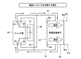
図6はスイッチ部56を示す図である。図6に示すように、制御装置55は、電源装置51およびスイッチ部56の両方に電気的に接続されており、これら電源装置51の動作およびスイッチ部56の動作を独立して制御可能である。スイッチ部56は、2つのスイッチ65を備えている。これらスイッチ65の一方は電源接続線66によって電源装置51の陽極側に接続されており、スイッチ65の他方は電源接続線66によって電源装置51の陰極側に接続されている。
FIG. 6 is a diagram showing a
スイッチ部56および熱電変換素子50は2つの素子接続線67によって互いに接続されている。より具体的には、各素子接続線67の一端は熱電変換素子50に接続されており、他端は各スイッチ65を介して各電源接続線66に接続可能である。2つの素子接続線67のそれぞれには、2つの分岐線68のそれぞれが接続されており、各分岐線68は各素子接続線67の途中から分岐している。各分岐線68の一端は各素子接続線67に接続されており、他端は各スイッチ65を介して各電源接続線66に接続可能である。
The
一実施形態では、複数の電解コンデンサ41Aが設けられる場合、熱電変換素子50の数および温度センサ70の数は電解コンデンサ41Aの数に対応しており、各温度センサ70は各電解コンデンサ41Aに隣接して配置される。スイッチ部56の数および電源装置51の数も電解コンデンサ41Aの数に対応してもよく、各スイッチ部56、各電源装置51、および各熱電変換素子50の接続構造は図6に示す実施形態と同様である。つまり、制御システムは、熱電変換素子50が電源装置51およびスイッチ部56に並列的に接続された構造を有している。
In one embodiment, when a plurality of
図4に示すように、制御装置55は、スイッチ部56に電気的に接続され、かつスイッチ部56のスイッチ65を切り替えるスイッチ切り替え部33を備えており、スイッチ切り替え部33は動作制御部32に接続されている。動作制御部32がスイッチ切り替え部33を動作させると、スイッチ切り替え部33はスイッチ部56のスイッチ65を切り替える。より具体的には、動作制御部32がスイッチ切り替え部33を動作(第1動作)させると、熱電変換素子50および電源装置51は、電源接続線66、分岐線68、および素子接続線67を介して接続される。動作制御部32がスイッチ切り替え部33を動作(第2動作)させると、熱電変換素子50および電源装置51は、電源接続線66および素子接続線67を介して接続される。
As shown in FIG. 4, the
図7および図8は熱電変換素子50に流れる電流の方向を説明するための図である。図7は、熱電変換素子50に流れる電流の方向が第1電流方向(つまり、電解コンデンサ41Aの熱をインバータ取り付け部材23に伝達させる方向)であるときの電流の流れを示している。図8は、熱電変換素子50に流れる電流の方向が第2電流方向(つまり、インバータ取り付け部材23の熱を電解コンデンサ41Aに伝達させる方向)であるときの電流の流れを示している。
7 and 8 are diagrams for explaining the direction of the current flowing through the
図7に示すように、スイッチ切り替え部33の第1動作により、電源接続線66および分岐線68はスイッチ65を介して接続される。電源装置51が電力を熱電変換素子50に供給すると、電流は、電源接続線66、分岐線68、および素子接続線67を通じて熱電変換素子50に流れる。この第1電流方向に流れる電流によって、熱電変換素子50には、その一方の面(電解コンデンサ側接触面)50aから反対側の面(インバータ取り付け部材側接触面)50bに向かって移動する熱流が発生し、結果として、電解コンデンサ41Aは冷却される。
As shown in FIG. 7, the
図8に示すように、スイッチ切り替え部33の第2動作により、電源接続線66および素子接続線67はスイッチ65を介して接続される。電源装置51が電力を熱電変換素子50に供給すると、電流は、電源接続線66および素子接続線67を通じて熱電変換素子50に流れる。この第2電流方向に流れる電流によって、熱電変換素子50には、反対側の面(インバータ取り付け部材側接触面)50bから一方の面(電解コンデンサ側接触面)50aに向かって移動する熱流が発生し、結果として、電解コンデンサ41Aは加熱される。
As shown in FIG. 8, the power
電解コンデンサ41Aを加熱する理由は次の通りである。インバータユニット3は寒冷地などの極寒の環境下で使用される場合がある。この場合、電解コンデンサ41Aの周囲温度が低いと、電解コンデンサ41Aの温度も低くなり、電解コンデンサ41Aの静電容量が低下することがある。この場合、電解コンデンサ41Aを積極的に加熱して電解コンデンサ41Aの静電容量の低下を防ぐことで、インバータユニット3の電力変換性能を安定させることが望ましい。本実施形態では、制御装置55は、スイッチ部56の動作の制御により、熱電変換素子50を介して熱電変換素子50を加熱することができるため、電解コンデンサ41Aの周囲温度が低くても電解コンデンサ41Aの静電容量の低下を防止することができる。
The reason for heating the
制御装置55の記憶部には、電解コンデンサ41Aの加熱を開始すべき温度の値である加熱開始しきい値が記憶されてもよい。加熱開始しきい値は冷却開始しきい値および給電停止しきい値よりも小さい値であり、任意に決定されてもよい。加熱開始しきい値は、例えば0[℃]である。
A heating start threshold value, which is a value of the temperature at which heating of the
図9は制御装置55の処理フローを示す図である。温度センサ70は、インバータユニット3の起動時またはインバータユニット3の起動直後に、電解コンデンサ41Aの温度(より具体的には、電解コンデンサ41Aの周囲温度)を検出し、監視部30は電解コンデンサ41Aの温度の監視を開始する(図9のステップS201参照)。判定部31は、温度センサ70によって検出された電解コンデンサ41Aの温度と加熱開始しきい値とを比較する(図9のステップS202参照)。電解コンデンサ41Aの温度が加熱開始しきい値以下である場合(図9のステップS202の「YES」参照)、判定部31は、その結果を示す信号を動作制御部32に送る。動作制御部32が判定部31からの信号を受けると、動作制御部32はスイッチ切り替え部33に対してスイッチ部56を動作させるように指令を出す。
FIG. 9 is a diagram showing a processing flow of the
スイッチ切り替え部33は、スイッチ部56を動作させて、熱電変換素子50に流れる電流の方向を第2電流方向に切り替える(図8参照)。動作制御部32は、電力が熱電変換素子50に供給されるように電源装置51を動作させる。電源装置51が電力を熱電変換素子50に供給すると、電流は第2電流方向に流れる。結果として、インバータ取り付け部材23の熱は電解コンデンサ41Aに伝達され、電解コンデンサ41Aは加熱される(図9のステップS203参照)。その後、判定部31は、電解コンデンサ41Aの温度が給電停止しきい値まで上昇したか否かを判定する(図9のステップS204参照)。
The
電解コンデンサ41Aの温度が加熱開始しきい値以下でない場合、すなわち、電解コンデンサ41Aの温度が加熱開始しきい値よりも高い場合(図9のステップS202の「NO」参照)、制御装置55は、電解コンデンサ41Aの加熱が不要であると判断して、電解コンデンサ41Aの加熱動作を実行しない。
When the temperature of the
電解コンデンサ41Aの温度が給電停止しきい値まで上昇した場合(図9のステップS204の「YES」参照)、判定部31は、その結果を示す信号を動作制御部32に送る。動作制御部32が判定部31からの信号を受けると、動作制御部32は、電源装置51を動作させて、電源装置51から熱電変換素子50への電力の供給を停止させる(図9のステップS205参照)。電解コンデンサ41Aの温度が給電停止しきい値まで上昇していない場合(図9のステップS204の「NO」参照)、監視部30は電解コンデンサ41Aの温度の監視を継続する。
When the temperature of the
図9のステップS205の後、制御装置55は図5に示す処理フロー(ステップS101~ステップS105)を実行する。より具体的には、判定部31が電解コンデンサ41Aの温度が冷却開始しきい値まで上昇したと判断した場合(図5のステップS102の「YES」参照)、動作制御部32は、判定部31からの判定結果を示す信号に基づいて、スイッチ切り替え部33に対してスイッチ部56を動作させるように指令を出す。
After step S205 in FIG. 9, the
スイッチ切り替え部33は、スイッチ部56を動作させて、熱電変換素子50に流れる電流の方向を第1電流方向に切り替える(図7参照)。動作制御部32は、電力が熱電変換素子50に供給されるように電源装置51を動作させる。電源装置51が電力を熱電変換素子50に供給すると、電流は第1電流方向に流れる。結果として、電解コンデンサ41Aの熱はインバータ取り付け部材23に伝達され、電解コンデンサ41Aは冷却される(図5のステップS103参照)。なお、判定部31が電解コンデンサ41Aの温度が冷却開始しきい値まで上昇したと判断しない場合(図5のステップS102の「NO」参照)、監視部30は電解コンデンサ41Aの温度の監視を継続する。
The
本実施形態によれば、電源装置51に接続されたスイッチ部56を設けることにより、制御装置55は、スイッチ部56を介して熱電変換素子50に入力される電流の方向を第1電流方向と第2電流方向との間で切り替えることができる。このような構成により、制御装置55は、電解コンデンサ41Aの温度がある一定の範囲内となるように、電解コンデンサ41Aの温度を精度よく制御することができる。
According to the present embodiment, by providing the
図10はインバータユニット3の他の実施形態を示す図である。図11は電解コンデンサ41Aがコンデンサケース75に収容される様子を示す図である。特に説明しない本実施形態の構成は、上述した実施形態と同じであるので、その重複する説明を省略する。図10および図11に示すように、インバータユニット3は、インバータ取り付け部材23の内面23aに接触し、電解コンデンサ41Aを収容するコンデンサケース75を備えてもよい。
FIG. 10 is a diagram showing another embodiment of the
コンデンサケース75は、筒状の壁部76と、壁部76に接続され、壁部76の一端を閉じる底部77とを備える収容部材であり、電解コンデンサ41Aを収容可能な大きさを有している。壁部76の他端は開口しており、電解コンデンサ41Aはこの開口を通じてコンデンサケース75に挿入される。
The
図10および図11に示すように、熱電変換素子50はコンデンサケース75の内面に貼り付けられている。電解コンデンサ41Aがコンデンサケース75に収容されたとき、熱電変換素子50の一方の面(電解コンデンサ側接触面)50aは電解コンデンサ41Aに接触し、熱電変換素子50の反対側の面(コンデンサケース側接触面)50bはコンデンサケース75の内面に接触する。
As shown in FIGS. 10 and 11, the
図10および図11に示す実施形態では、熱電変換素子50は、コンデンサケース75の内面の全体に貼り付けられている。より具体的には、熱電変換素子50は、コンデンサケース75の壁部76の内壁面(内周面)および底部77の内面に貼り付けられている。一実施形態では、熱電変換素子50は、コンデンサケース75の内面の一部に貼り付けられてもよい。
In the embodiment shown in FIGS. 10 and 11, the
本実施形態では、熱電変換素子50は、特許文献1(特開2016-9838号公報)に記載された薄膜形状を有するテープ状の熱電変換素子と同様の熱電変換構造を有している。このようなシート形状を有する熱電変換素子50は、その配置箇所が制限されることなく、コンデンサケース75の内面に貼り付けられる。
In the present embodiment, the
基板42の挿入孔42cはコンデンサケース75が挿入可能な大きさを有しており、挿入孔42cの直径はコンデンサケース75の壁部76の外径よりも大きい。一実施形態では、挿入孔42cを設ける代わりに、基板42の外周面から内側に向かって延びる切り欠きが設けられてもよい。コンデンサケース75は、電解コンデンサ41Aの本体部60の底面60bがコンデンサケース75を介してインバータ取り付け部材23の内面23aと対向するように、挿入孔42cに挿入されている。コンデンサケース75が基板42の挿入孔42cに挿入されると、コンデンサケース75の底部77の外面はインバータ取り付け部材23の内面23aに接触する。底部77の外面は、コンデンサケース75の内面の一部を構成する底部77の内面とは反対側の面である。
The
温度センサ70はコンデンサケース75に隣接して配置されている。本実施形態では、温度センサ70は基板42の実装面42a上に配置されているが、コンデンサケース75に直接取り付けられてもよい。制御装置55は、温度センサ70によって検出された温度を監視し、この温度が冷却開始しきい値まで上昇した場合、電源装置51から熱電変換素子50に電力を供給させて、電解コンデンサ41Aの熱をコンデンサケース75に伝達させる。コンデンサケース75に伝達された熱はインバータ取り付け部材23に伝達され、結果として、電解コンデンサ41Aはコンデンサケース75を介して放熱される。
The
コンデンサケース75は、アルミニウム(Al)などの熱伝導性に優れた材料(金属)から構成されていることが好ましい。本実施形態によれば、コンデンサケース75は、電解コンデンサ41Aと熱電変換素子50との接触面積を大きくすることができるため、熱電変換素子50の冷却性能を向上させることができる。熱電変換素子50を加熱する場合も同様に、コンデンサケース75は、熱電変換素子50の加熱性能を向上させることができる。
The
本実施形態においても、制御装置55の記憶部には、冷却開始しきい値、給電停止しきい値、および加熱開始しきい値が記憶されていてもよい。制御装置55は、上述した実施形態と同様に、これら冷却開始しきい値、給電停止しきい値、および加熱開始しきい値に基づいて、電源装置51(およびスイッチ部56)の動作を制御してもよい。
Also in the present embodiment, the cooling start threshold value, the power supply stop threshold value, and the heating start threshold value may be stored in the storage unit of the
スイッチ部56は、熱電変換素子50に流れる電流の方向を、電解コンデンサ41Aの熱をコンデンサケース75に伝達させる第1電流方向とコンデンサケース75の熱を電解コンデンサ41Aに伝達させる第2電流方向との間で切り替える。制御装置55は、温度センサ70によって検出された温度が冷却開始しきい値まで上昇した場合、スイッチ部56を動作させて、熱電変換素子50に流れる電流の方向を第1電流方向に切り替える。この状態で、電源装置51が熱電変換素子50に電力を供給すると、電解コンデンサ41Aの熱はコンデンサケース75を介してインバータ取り付け部材23に伝達される。
The
制御装置55は、上記温度が加熱開始しきい値以下である場合、スイッチ部56を動作させて、熱電変換素子50に流れる電流の方向を第2電流方向に切り替える。この状態で、電源装置51が熱電変換素子50に電力を供給すると、インバータ取り付け部材23の熱はコンデンサケース75を介して電解コンデンサ41Aに伝達される。
When the temperature is equal to or lower than the heating start threshold value, the
以下、インバータユニット3が適用可能な機械装置の一例について図面を参照しつつ説明する。図12はインバータユニット3を備えた電動機組立体1を示す図である。特に説明しない本実施形態の構成は、上述した実施形態と同じであるので、その重複する説明を省略する。
Hereinafter, an example of a mechanical device to which the
電動機組立体1は、インバータ20が内蔵された一体型構造を有する機械装置である。図12に示すように、電動機組立体1は、モータ部2と、インバータ部としてのインバータユニット3とを備えている。電動機組立体1は、駆動軸5と、駆動軸5を回転させる回転子(ロータ)6および固定子(ステータ)7を備えるモータ(回転要素)8と、モータ8を収容するモータケーシング10と、モータ8に隣接して配置され、モータ8の動作(回転速度)を制御するインバータ20と、インバータ20を収容し、駆動軸5の軸線CL方向に沿ってモータケーシング10に直列的に配置されたインバータケース21とを備えている。
The
モータケーシング10およびインバータケース21は駆動軸5と同心状に配置されている。本実施形態では、モータケーシング10およびインバータケース21は、駆動軸5の軸線CL方向に直列的に配置されているため、電動機組立体1はコンパクトな構造を有することができる。
The
モータケーシング10の内部には、モータ8が配置されている。モータ8は、駆動軸5に固定された回転子6と、回転子6を囲んで、外部(図示しない)からの電力を巻線(コイル)7bが受けて回転磁界を形成する固定子(ステータ)7とを備えている。固定子7は、ステータコア7aと、ステータコア7aに巻かれた複数の巻線7bとを備えている。回転子6は、回転子6と固定子7との間に形成される回転磁界によって回転し、回転子6が固定された駆動軸5は回転子6とともに回転する。
A
図12において、モータ8は模式的に描かれている。モータ8は、例えば、ロータに永久磁石を用いた永久磁石型モータである。しかしながら、モータ8は、永久磁石型モータに限定されず、誘導モータやSRモータなど、様々な種類のモータであってもよい。
In FIG. 12, the
モータケーシング10は、固定子7が固定された筒状のモータフレーム11と、モータフレーム11の一方の開口端を閉じ、かつ駆動軸5が貫通する貫通孔29が形成されたエンドカバー12と、モータフレーム11の他方の開口端を閉じるブラケット13とを備えている。エンドカバー12およびブラケット13は、モータ8を挟んで互いに対向している。駆動軸5は、エンドカバー12の軸受支持部25に支持された軸受27およびブラケット13の軸受支持部26に支持された軸受28によって回転自在に支持されている。
The
モータフレーム11の外面には、駆動軸5の軸線CL方向に延びる複数のフィン35が配置されている。これらフィン35は、モータフレーム11の外面から外側に向かって延びており、モータフレーム11の周方向に沿って等間隔に配置されている。モータフレーム11の外面は固定子7が固定されたモータフレーム11の内面とは反対側の面である。
On the outer surface of the
インバータケース21は、インバータ20を取り囲む筒状のインバータフレーム22と、インバータフレーム22の開口端を閉じるインバータ取り付け部材23とを備えている。インバータ取り付け部材23はカバー部材とも呼ばれてもよい。インバータフレーム22の外面には、駆動軸5の軸線CL方向に延びる複数のフィン37が配置されている。これらフィン37は、インバータフレーム22の外面から外側に向かって延びており、インバータフレーム22の周方向に沿って等間隔に配置されている。インバータフレーム22の外面はインバータ20の周囲に配置されたインバータフレーム22の内面とは反対側の面である。
The
インバータフレーム22のインバータ取り付け部材23側の面およびインバータ取り付け部材23のインバータフレーム22側の面は、それぞれ嵌め合い構造を有しており、これらインバータフレーム22およびインバータ取り付け部材23は、嵌め合いによって互いに接続されている。
The surface of the
インバータフレーム22のブラケット13側の面およびブラケット13のインバータフレーム22側の面は、それぞれ嵌め合い構造を有しており、これらインバータフレーム22およびブラケット13は、嵌め合いによって互いに接続されている。
The surface of the
図12に示すように、電動機組立体1は密閉構造を有しており、インバータ20、すなわち、インバータ要素41および基板42はインバータケース21およびブラケット13によって形成された密閉空間に配置されている。発熱源であるインバータ20がこのような密閉空間で駆動されると、電解コンデンサ41Aの周囲温度は比較的高くなりやすく、電解コンデンサ41Aの寿命が短くなるおそれがある。したがって、このような密閉構造を有する電動機組立体1では、電解コンデンサ41Aを積極的に冷却して電解コンデンサ41Aの長寿命化を図る必要性がより高い。
As shown in FIG. 12, the
電解コンデンサ41Aを放熱するために、インバータ20が配置される密閉空間の大きさを大きくしたり、ヒートシンクとしてのインバータ取り付け部材23の大きさを大きくすることが考えられる。しかしながら、これらのような構成では、電動機組立体1の全体の大きさが大きくなってしまう。
In order to dissipate heat from the
本実施形態によれば、熱電変換素子50は、そのペルチェ効果により電解コンデンサ41Aをインバータ取り付け部材23に積極的に放熱することができるため、電解コンデンサ41Aを放熱するための大きなスペースは不要である。したがって、インバータ20が配置された密閉空間の大きさを比較的小さくすることができ、さらに、インバータ取り付け部材23の大きさも比較的小さくすることができる。結果として、電動機組立体1は、そのサイズを全体的に小さくすることができる。なお、図示しないが、コンデンサケース75(図10および図11参照)を備えたインバータユニット3の構成も電動機組立体1に適用することができる。
According to the present embodiment, the
これまで本発明の実施形態について説明したが、本発明は上述の実施形態に限定されず、その技術思想の範囲内において、種々の異なる形態で実施されてよいことは勿論である。 Although the embodiments of the present invention have been described so far, the present invention is not limited to the above-described embodiments, and it is needless to say that the present invention may be implemented in various different forms within the scope of the technical idea.
1 電動機組立体
2 モータ部
3 インバータユニット(インバータ部)
5 駆動軸
6 回転子
7 固定子
7a ステータコア
7b 巻線
8 モータ
10 モータケーシング
11 モータフレーム
12 エンドカバー
13 ブラケット
20 インバータ
21 インバータケース
22 インバータフレーム
23 インバータ取り付け部材
23a 内面
23b 外面
25 軸受支持部
26 軸受支持部
27 軸受
28 軸受
29 貫通孔
30 監視部
31 判定部
32 動作制御部
33 スイッチ切り替え部
35,36,37 フィン
41 インバータ要素
41A 電解コンデンサ
41B パワー素子
42 基板
42a 実装面
42b 裏面
42c 挿入孔
50 熱電変換素子
50a 一方の面
50b 反対側の面
51 電源装置
55 制御装置
56 スイッチ部
60 本体部
60a 端子面
60b 底面
60c 外周面
61 端子
62 リード線
65 スイッチ
66 電源接続線
67 素子接続線
68 分岐線
70 温度センサ
75 コンデンサケース
76 壁部
77 底部
1
5 Drive
Claims (8)
前記電解コンデンサが接続された基板と、
前記基板が取り付けられたインバータ取り付け部材と、
前記電解コンデンサと前記インバータ取り付け部材の内面との間に配置された熱電変換素子と、
前記熱電変換素子に電気的に接続され、前記熱電変換素子に電力を供給する電源装置と、
前記電源装置に電気的に接続され、前記電源装置の動作を制御する制御装置とを備え、
前記熱電変換素子は、前記電解コンデンサに接触する一方の面と、該一方の面の反対側に位置し、前記インバータ取り付け部材の内面に接触する反対側の面とを有しており、
前記基板は、前記インバータ取り付け部材の内面と平行に配置されており、かつ前記電解コンデンサが挿入可能な大きさを有する挿入孔を有しており、
前記電解コンデンサは、前記電解コンデンサの底面が前記熱電変換素子を介して前記インバータ取り付け部材の内面と対向するように、前記挿入孔に挿入されており、
前記制御装置は、前記電源装置から前記熱電変換素子に電力を供給させて、前記電解コンデンサの熱を前記インバータ取り付け部材に伝達させることを特徴とするインバータユニット。 Inverter elements including electrolytic capacitors and
The board to which the electrolytic capacitor is connected and
Inverter mounting member to which the board is mounted and
A thermoelectric conversion element arranged between the electrolytic capacitor and the inner surface of the inverter mounting member,
A power supply device that is electrically connected to the thermoelectric conversion element and supplies electric power to the thermoelectric conversion element.
It is provided with a control device that is electrically connected to the power supply device and controls the operation of the power supply device.
The thermoelectric conversion element has one surface in contact with the electrolytic capacitor and the opposite surface located on the opposite side of the one surface and in contact with the inner surface of the inverter mounting member.
The substrate is arranged parallel to the inner surface of the inverter mounting member, and has an insertion hole having a size into which the electrolytic capacitor can be inserted.
The electrolytic capacitor is inserted into the insertion hole so that the bottom surface of the electrolytic capacitor faces the inner surface of the inverter mounting member via the thermoelectric conversion element.
The control device is an inverter unit characterized in that electric power is supplied from the power supply device to the thermoelectric conversion element and the heat of the electrolytic capacitor is transferred to the inverter mounting member.
前記制御装置は、
前記温度センサによって検出された温度を監視し、
前記温度が冷却開始しきい値まで上昇した場合、前記電源装置から前記熱電変換素子に電力を供給させて、前記電解コンデンサの熱を前記インバータ取り付け部材に伝達させることを特徴とする請求項1に記載のインバータユニット。 The inverter unit includes a temperature sensor arranged adjacent to the electrolytic capacitor.
The control device is
Monitor the temperature detected by the temperature sensor and
The first aspect of the present invention is characterized in that when the temperature rises to the cooling start threshold value, electric power is supplied from the power supply device to the thermoelectric conversion element to transfer the heat of the electrolytic capacitor to the inverter mounting member. The described inverter unit.
前記制御装置は、
前記温度が前記冷却開始しきい値まで上昇した場合、前記スイッチ部を動作させて、前記熱電変換素子に流れる電流の方向を前記第1電流方向に切り替え、
前記温度が前記冷却開始しきい値よりも小さな加熱開始しきい値以下である場合、前記スイッチ部を動作させて、前記熱電変換素子に流れる電流の方向を前記第2電流方向に切り替えることを特徴とする請求項2に記載のインバータユニット。 In the inverter unit, the direction of the current flowing through the thermoelectric conversion element is the first current direction for transmitting the heat of the electrolytic capacitor to the inverter mounting member and the second current for transmitting the heat of the inverter mounting member to the electrolytic capacitor. Equipped with a switch to switch between directions
The control device is
When the temperature rises to the cooling start threshold value, the switch unit is operated to switch the direction of the current flowing through the thermoelectric conversion element to the first current direction.
When the temperature is equal to or less than the heating start threshold value smaller than the cooling start threshold value, the switch unit is operated to switch the direction of the current flowing through the thermoelectric conversion element to the second current direction. The inverter unit according to claim 2.
前記電解コンデンサが接続された基板と、
前記基板が取り付けられたインバータ取り付け部材と、
前記インバータ取り付け部材の内面に接触し、前記電解コンデンサを収容するコンデンサケースと、
前記コンデンサケースの内面に貼り付けられた熱電変換素子と、
前記熱電変換素子に電気的に接続され、前記熱電変換素子に電力を供給する電源装置と、
前記電源装置に電気的に接続され、前記電源装置の動作を制御する制御装置とを備え、
前記熱電変換素子は、前記電解コンデンサに接触する一方の面と、該一方の面の反対側に位置し、前記コンデンサケースの内面に接触する反対側の面とを有しており、
前記基板は、前記インバータ取り付け部材の内面と平行に配置されており、かつ前記コンデンサケースが挿入可能な大きさを有する挿入孔を有しており、
前記コンデンサケースは、前記電解コンデンサの底面が前記コンデンサケースを介して前記インバータ取り付け部材の内面と対向するように、前記挿入孔に挿入されており、
前記制御装置は、前記電源装置から前記熱電変換素子に電力を供給させて、前記電解コンデンサの熱を前記コンデンサケースに伝達させることを特徴とするインバータユニット。 Inverter elements including electrolytic capacitors and
The board to which the electrolytic capacitor is connected and
Inverter mounting member to which the board is mounted and
A capacitor case that comes into contact with the inner surface of the inverter mounting member and houses the electrolytic capacitor,
The thermoelectric conversion element attached to the inner surface of the capacitor case and
A power supply device that is electrically connected to the thermoelectric conversion element and supplies electric power to the thermoelectric conversion element.
It is provided with a control device that is electrically connected to the power supply device and controls the operation of the power supply device.
The thermoelectric conversion element has one surface in contact with the electrolytic capacitor and the opposite surface located on the opposite side of the one surface and in contact with the inner surface of the capacitor case.
The substrate is arranged parallel to the inner surface of the inverter mounting member, and has an insertion hole having a size capable of inserting the capacitor case.
The capacitor case is inserted into the insertion hole so that the bottom surface of the electrolytic capacitor faces the inner surface of the inverter mounting member via the capacitor case.
The control device is an inverter unit characterized in that electric power is supplied from the power supply device to the thermoelectric conversion element and the heat of the electrolytic capacitor is transferred to the capacitor case.
前記制御装置は、
前記温度センサによって検出された温度を監視し、
前記温度が冷却開始しきい値まで上昇した場合、前記電源装置から前記熱電変換素子に電力を供給させて、前記電解コンデンサの熱を前記コンデンサケースに伝達させることを特徴とする請求項4に記載のインバータユニット。 The inverter unit includes a temperature sensor arranged adjacent to the capacitor case.
The control device is
Monitor the temperature detected by the temperature sensor and
The fourth aspect of claim 4 , wherein when the temperature rises to the cooling start threshold value, electric power is supplied from the power supply device to the thermoelectric conversion element to transfer the heat of the electrolytic capacitor to the capacitor case. Inverter unit.
前記制御装置は、
前記温度が前記冷却開始しきい値まで上昇した場合、前記スイッチ部を動作させて、前記熱電変換素子に流れる電流の方向を前記第1電流方向に切り替え、
前記温度が前記冷却開始しきい値よりも小さな加熱開始しきい値以下である場合、前記スイッチ部を動作させて、前記熱電変換素子に流れる電流の方向を前記第2電流方向に切り替えることを特徴とする請求項5に記載のインバータユニット。 In the inverter unit, the direction of the current flowing through the thermoelectric conversion element is the first current direction for transmitting the heat of the electrolytic capacitor to the capacitor case and the second current direction for transmitting the heat of the capacitor case to the electrolytic capacitor. Equipped with a switch section to switch between
The control device is
When the temperature rises to the cooling start threshold value, the switch unit is operated to switch the direction of the current flowing through the thermoelectric conversion element to the first current direction.
When the temperature is equal to or less than the heating start threshold value smaller than the cooling start threshold value, the switch unit is operated to switch the direction of the current flowing through the thermoelectric conversion element to the second current direction. The inverter unit according to claim 5 .
前記駆動軸を回転させる回転子および固定子を備えるモータと、
前記モータを収容するモータケーシングと、
前記モータの回転速度を制御するためのインバータユニットとを備え、
前記インバータユニットは、
電解コンデンサを含むインバータ要素と、
前記電解コンデンサが接続された基板と、
前記モータケーシングに接続されたインバータフレームの開口端を閉じ、かつ前記基板が取り付けられるインバータ取り付け部材と、
前記電解コンデンサと前記インバータ取り付け部材の内面との間に配置された熱電変換素子と、
前記熱電変換素子に電気的に接続され、前記熱電変換素子に電力を供給する電源装置と、
前記電源装置に電気的に接続され、前記電源装置の動作を制御する制御装置とを備えており、
前記熱電変換素子は、前記電解コンデンサに接触する一方の面と、該一方の面の反対側に位置し、前記インバータ取り付け部材の内面に接触する反対側の面とを有しており、
前記基板は、前記インバータ取り付け部材の内面と平行に配置されており、かつ前記電解コンデンサが挿入可能な大きさを有する挿入孔を有しており、
前記電解コンデンサは、前記電解コンデンサの底面が前記熱電変換素子を介して前記インバータ取り付け部材の内面と対向するように、前記挿入孔に挿入されており、
前記制御装置は、前記電源装置から前記熱電変換素子に電力を供給させて、前記電解コンデンサの熱を前記インバータ取り付け部材に伝達させることを特徴とする電動機組立体。 Drive shaft and
A motor including a rotor and a stator that rotate the drive shaft,
The motor casing that houses the motor and
It is equipped with an inverter unit for controlling the rotation speed of the motor.
The inverter unit is
Inverter elements including electrolytic capacitors and
The board to which the electrolytic capacitor is connected and
An inverter mounting member that closes the open end of the inverter frame connected to the motor casing and to which the substrate is mounted.
A thermoelectric conversion element arranged between the electrolytic capacitor and the inner surface of the inverter mounting member,
A power supply device that is electrically connected to the thermoelectric conversion element and supplies electric power to the thermoelectric conversion element.
It is provided with a control device that is electrically connected to the power supply device and controls the operation of the power supply device.
The thermoelectric conversion element has one surface in contact with the electrolytic capacitor and the opposite surface located on the opposite side of the one surface and in contact with the inner surface of the inverter mounting member.
The substrate is arranged parallel to the inner surface of the inverter mounting member, and has an insertion hole having a size into which the electrolytic capacitor can be inserted.
The electrolytic capacitor is inserted into the insertion hole so that the bottom surface of the electrolytic capacitor faces the inner surface of the inverter mounting member via the thermoelectric conversion element.
The control device is an electric motor assembly characterized in that electric power is supplied from the power supply device to the thermoelectric conversion element and the heat of the electrolytic capacitor is transferred to the inverter mounting member.
前記駆動軸を回転させる回転子および固定子を備えるモータと、
前記モータを収容するモータケーシングと、
前記モータの回転速度を制御するためのインバータユニットとを備え、
前記インバータユニットは、
電解コンデンサを含むインバータ要素と、
前記電解コンデンサが接続された基板と、
前記モータケーシングに接続されたインバータフレームの開口端を閉じ、かつ前記基板が取り付けられるインバータ取り付け部材と、
前記インバータ取り付け部材の内面に接触し、前記電解コンデンサを収容するコンデンサケースと、
前記コンデンサケースの内面に貼り付けられた熱電変換素子と、
前記熱電変換素子に電気的に接続され、前記熱電変換素子に電力を供給する電源装置と、
前記電源装置に電気的に接続され、前記電源装置の動作を制御する制御装置とを備えており、
前記熱電変換素子は、前記電解コンデンサに接触する一方の面と、該一方の面の反対側に位置し、前記コンデンサケースの内面に接触する反対側の面とを有しており、
前記基板は、前記インバータ取り付け部材の内面と平行に配置されており、かつ前記コンデンサケースが挿入可能な大きさを有する挿入孔を有しており、
前記コンデンサケースは、前記電解コンデンサの底面が前記コンデンサケースを介して前記インバータ取り付け部材の内面と対向するように、前記挿入孔に挿入されており、
前記制御装置は、前記電源装置から前記熱電変換素子に電力を供給させて、前記電解コンデンサの熱を前記コンデンサケースに伝達させることを特徴とする電動機組立体。 Drive shaft and
A motor including a rotor and a stator that rotate the drive shaft,
The motor casing that houses the motor and
It is equipped with an inverter unit for controlling the rotation speed of the motor.
The inverter unit is
Inverter elements including electrolytic capacitors and
The board to which the electrolytic capacitor is connected and
An inverter mounting member that closes the open end of the inverter frame connected to the motor casing and to which the substrate is mounted.
A capacitor case that comes into contact with the inner surface of the inverter mounting member and houses the electrolytic capacitor,
The thermoelectric conversion element attached to the inner surface of the capacitor case and
A power supply device that is electrically connected to the thermoelectric conversion element and supplies electric power to the thermoelectric conversion element.
It is provided with a control device that is electrically connected to the power supply device and controls the operation of the power supply device.
The thermoelectric conversion element has one surface in contact with the electrolytic capacitor and the opposite surface located on the opposite side of the one surface and in contact with the inner surface of the capacitor case.
The substrate is arranged parallel to the inner surface of the inverter mounting member, and has an insertion hole having a size capable of inserting the capacitor case.
The capacitor case is inserted into the insertion hole so that the bottom surface of the electrolytic capacitor faces the inner surface of the inverter mounting member via the capacitor case.
The control device is an electric motor assembly characterized in that electric power is supplied from the power supply device to the thermoelectric conversion element and the heat of the electrolytic capacitor is transferred to the capacitor case.
Priority Applications (1)
| Application Number | Priority Date | Filing Date | Title |
|---|---|---|---|
| JP2018029369A JP7014635B2 (en) | 2018-02-22 | 2018-02-22 | Inverter unit and motor assembly |
Applications Claiming Priority (1)
| Application Number | Priority Date | Filing Date | Title |
|---|---|---|---|
| JP2018029369A JP7014635B2 (en) | 2018-02-22 | 2018-02-22 | Inverter unit and motor assembly |
Publications (2)
| Publication Number | Publication Date |
|---|---|
| JP2019146396A JP2019146396A (en) | 2019-08-29 |
| JP7014635B2 true JP7014635B2 (en) | 2022-02-01 |
Family
ID=67773295
Family Applications (1)
| Application Number | Title | Priority Date | Filing Date |
|---|---|---|---|
| JP2018029369A Active JP7014635B2 (en) | 2018-02-22 | 2018-02-22 | Inverter unit and motor assembly |
Country Status (1)
| Country | Link |
|---|---|
| JP (1) | JP7014635B2 (en) |
Families Citing this family (1)
| Publication number | Priority date | Publication date | Assignee | Title |
|---|---|---|---|---|
| WO2026013759A1 (en) * | 2024-07-09 | 2026-01-15 | 三菱電機株式会社 | Inverter device, refrigeration cycle device, and inverter control method |
Citations (4)
| Publication number | Priority date | Publication date | Assignee | Title |
|---|---|---|---|---|
| JP2000146354A (en) | 1998-11-12 | 2000-05-26 | Kazuo Kono | Temperature control device of thermo module for electronic cooling and heating |
| JP2007180155A (en) | 2005-12-27 | 2007-07-12 | Toyota Motor Corp | Capacitor device |
| JP2011217463A (en) | 2010-03-31 | 2011-10-27 | Toyota Industries Corp | Inverter device |
| JP2014150215A (en) | 2013-02-04 | 2014-08-21 | Jtekt Corp | Cooling device and motor control device including the same |
Family Cites Families (2)
| Publication number | Priority date | Publication date | Assignee | Title |
|---|---|---|---|---|
| JPH0947038A (en) * | 1995-07-27 | 1997-02-14 | Mitsubishi Electric Corp | Condenser cooling device |
| JPH0984302A (en) * | 1995-09-11 | 1997-03-28 | Mitsubishi Electric Corp | Motor device with built-in drive circuit |
-
2018
- 2018-02-22 JP JP2018029369A patent/JP7014635B2/en active Active
Patent Citations (4)
| Publication number | Priority date | Publication date | Assignee | Title |
|---|---|---|---|---|
| JP2000146354A (en) | 1998-11-12 | 2000-05-26 | Kazuo Kono | Temperature control device of thermo module for electronic cooling and heating |
| JP2007180155A (en) | 2005-12-27 | 2007-07-12 | Toyota Motor Corp | Capacitor device |
| JP2011217463A (en) | 2010-03-31 | 2011-10-27 | Toyota Industries Corp | Inverter device |
| JP2014150215A (en) | 2013-02-04 | 2014-08-21 | Jtekt Corp | Cooling device and motor control device including the same |
Also Published As
| Publication number | Publication date |
|---|---|
| JP2019146396A (en) | 2019-08-29 |
Similar Documents
| Publication | Publication Date | Title |
|---|---|---|
| US9431881B2 (en) | Electric machine housing | |
| US6992409B2 (en) | Liquid-cooled rotary electric machine integrated with an inverter | |
| JP3985760B2 (en) | Rotating electrical machine system | |
| CN101006633B (en) | Rotating electric machine | |
| US2897383A (en) | Alternating current dynamoelectric machine | |
| JP6371001B2 (en) | Power converter | |
| US9203288B2 (en) | Rotary electric machine with power converter | |
| WO2013042486A1 (en) | Mechatronically integrated module | |
| US20070103101A1 (en) | Rotating electric machine with built-in control device | |
| CN107852071B (en) | Rotating electrical machine | |
| JP6621491B2 (en) | Rotating electric machine | |
| JPH10322973A (en) | Electric motor with power converter | |
| JP5893179B1 (en) | Controller-integrated rotating electrical machine | |
| US20160020679A1 (en) | Inverter-integrated motor | |
| JP6614208B2 (en) | Rotating electric machine | |
| JP2009124903A (en) | Controller-integrated rotating electrical machine | |
| CN100508333C (en) | Motor with rotating fan | |
| JP2019522456A (en) | Electric motor | |
| JP5634202B2 (en) | Electric compressor and control device thereof | |
| US20200100393A1 (en) | Motor, printed circuit board, and engine cooling fan module including the motor | |
| JP2019146396A (en) | Inverter unit and electric motor assembly | |
| JP2017184295A (en) | Dynamo-electric machine | |
| JP2004088983A (en) | Inverter-mounted rotary electric machine and circuit device | |
| JP2019129571A (en) | Electric motor assembly and control unit | |
| CN115868103A (en) | Electric machine |
Legal Events
| Date | Code | Title | Description |
|---|---|---|---|
| A621 | Written request for application examination |
Free format text: JAPANESE INTERMEDIATE CODE: A621 Effective date: 20201118 |
|
| A977 | Report on retrieval |
Free format text: JAPANESE INTERMEDIATE CODE: A971007 Effective date: 20210930 |
|
| A131 | Notification of reasons for refusal |
Free format text: JAPANESE INTERMEDIATE CODE: A131 Effective date: 20211026 |
|
| A521 | Request for written amendment filed |
Free format text: JAPANESE INTERMEDIATE CODE: A523 Effective date: 20211220 |
|
| TRDD | Decision of grant or rejection written | ||
| A01 | Written decision to grant a patent or to grant a registration (utility model) |
Free format text: JAPANESE INTERMEDIATE CODE: A01 Effective date: 20220111 |
|
| A61 | First payment of annual fees (during grant procedure) |
Free format text: JAPANESE INTERMEDIATE CODE: A61 Effective date: 20220120 |
|
| R150 | Certificate of patent or registration of utility model |
Ref document number: 7014635 Country of ref document: JP Free format text: JAPANESE INTERMEDIATE CODE: R150 |
|
| R250 | Receipt of annual fees |
Free format text: JAPANESE INTERMEDIATE CODE: R250 |
|
| R250 | Receipt of annual fees |
Free format text: JAPANESE INTERMEDIATE CODE: R250 |