JP4419258B2 - Turbo molecular pump - Google Patents
Turbo molecular pump Download PDFInfo
- Publication number
- JP4419258B2 JP4419258B2 JP2000062456A JP2000062456A JP4419258B2 JP 4419258 B2 JP4419258 B2 JP 4419258B2 JP 2000062456 A JP2000062456 A JP 2000062456A JP 2000062456 A JP2000062456 A JP 2000062456A JP 4419258 B2 JP4419258 B2 JP 4419258B2
- Authority
- JP
- Japan
- Prior art keywords
- phase
- molecular pump
- brushless motor
- excitation
- turbo molecular
- Prior art date
- Legal status (The legal status is an assumption and is not a legal conclusion. Google has not performed a legal analysis and makes no representation as to the accuracy of the status listed.)
- Expired - Lifetime
Links
Images


Landscapes
- Non-Positive Displacement Air Blowers (AREA)
- Brushless Motors (AREA)
Description
【0001】
【発明の属する技術分野】
本発明は、ターボ分子ポンプに関する。
【0002】
【従来の技術】
半導体製造装置などに用いられる真空ポンプの一つとしてターボ分子ポンプがあるが、ターボ分子ポンプでは回転翼が形成されたロータをモータで回転駆動し、この回転翼を固定翼に対して高速回転させることにより気体分子を排気している。ロータを回転駆動するモータとしては、DCブラシレスモータが知られている。DCブラシレスモータでは、ロータの磁極を検知してロータの回転位置を検出する複数のホールセンサがステータに設けられており、各ホールセンサの信号から論理回路によりステータコイルを励磁する際の励磁パターンを形成し、その励磁パターンによりモータ駆動回路を制御してモータの駆動を行う。
【0003】
例えば、3相(U,V,W)のステータコイルに対応して3つのホールセンサH1,H2,H3を設け、これら3つのホールセンサからの信号に基づいてロータの回転周期に同期した励磁電圧を各コイルU,V,Wに印加する。図10の(a)は各ホールセンサH1〜H3からのセンサ信号を示す図である。このセンサ信号から論理回路により励磁パターン信号が生成され、その信号によりモータ駆動回路が制御されて図10(b)に示すような励磁電圧がステータコイルU,V,Wに印加される。
【0004】
【発明が解決しようとする課題】
しかしながら、次のような理由からステータコイルに印加される励磁電圧は必ずしも最適なものとはならないという問題があった。
(a)ホールセンサのセンサ信号が励磁パターン形成回路に取り込まれるまでに生じるセンサ信号の位相のずれによって、励磁パターンが最適なものからずれてしまう。特に、信号経路にフォトカプラを用いた場合には、フォトカプラの応答時間に起因する位相のずれが生じる。
(b)ホールセンサは磁力を検出して図10(a)のように信号を反転するアナログ的な素子なので、素子のばらつきにより位相のずれが生じる。
(c)また、磁石の磁化が不均一であった場合、信号が反転する立ち上がりおよび立ち下がりにずれが生じる。
【0005】
上述するような原因でセンサ信号に位相ずれが生じると、この位相ずれは励磁パターンの位相ずれとなり、モータ駆動状態が最適な状態からずれてしまうことになる。その結果、不要な電力を消費することになり、ポンプ本体の温度上昇の原因となる。特に、磁気軸受式のターボ分子ポンプの場合には、ロータは真空中に非接触で浮上しているため、熱の逃げ場が無く、僅かな消費電力アップでも温度が上昇しやすい。例えば、無負荷回転時に70〜80Wの消費電力であったものが、上述したような原因で10Wアップした場合、5〜10℃もロータ温度が上昇する。
【0006】
ターボ分子ポンプではロータは非常に高速で回転しているため、一般的にアルミ合金からなるロータの温度が上昇すると、高温クリープによるロータの強度の低下を招くという問題があった。
【0007】
本発明の目的は、消費電力の低減を図ることができるDCブラシレスモータを使用したターボ分子ポンプを提供することにある。
【0008】
請求項1に係る発明は、DCブラシレスモータにより回転翼を固定翼に対して高速回転させるターボ分子ポンプにおいて、前記DCブラシレスモータに流れる負荷電流を検出する負荷電流検出手段と、前記ターボ分子ポンプが無負荷状態であって且つ所定の一定回転速度を維持しているときに外部から供給される最適位相検出指令に応答して、前記DCブラシレスモータの回転基準位置に対する励磁基準位置を相対的に変化させることにより、前記負荷電流が最小となる最適励磁位相を検出する最適位相検出手段と、前記最適位相検出手段により検出された前記最適励磁位相を最適位相情報として記憶しておく位相情報記憶手段と、前記ターボ分子ポンプの稼働時には、前記位相情報記憶手段に記憶されている前記最適位相情報に基づいて励磁パターンを形成することにより前記DCブラシレスモータを駆動する駆動手段とを備えている。この請求項1に記載した発明は、図11および図12に対応している。
請求項2に係る発明は、請求項1に記載のターボ分子ポンプにおいて、前記DCブラシレスモータの回転基準位置は、前記DCブラシレスモータのロータに埋め込まれた永久磁石の磁気を検出する単一の磁気検出素子から出力される信号により決定される。
【0009】
なお、本発明の構成を説明する上記課題を解決するための手段の項では、本発明を分かり易くするために発明の実施の形態の図を用いたが、これにより本発明が発明の実施の形態に限定されるものではない。
【0010】
【発明の実施の形態】
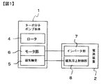
以下、図1〜図12を参照して本発明の実施の形態を説明する。図1は磁気軸受式ターボ分子ポンプの概略構成を示すブロック図であり、ターボ分子ポンプはターボ分子ポンプ本体1と電源装置2とから構成されている。ポンプ本体1に設けられたロータ4は磁気軸受5により非接触支持され、モータ部6により回転駆動される。モータ部6にはDCブラシレスモータが用いられる。一方、電源装置2には、DCブラシレスモータを駆動するインバータ部7と、ロータ4が所定浮上位置に支持されるように磁気軸受5に供給される励磁電流を制御する磁気浮上制御部8とを備えている。
【0011】
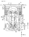
図2はターボ分子ポンプ本体1の詳細を示す断面図である。ポンプ本体1のケーシング20の内部には、複数段のロータ翼21およびネジ溝部22が形成されたロータ4と、ロータ翼21に対して交互に配設されるステータ翼23と、上記ネジ溝部22と対向するように配設される筒状部材24とが設けられている。ロータ4を非接触支持する磁気軸受5は、ラジアル磁気軸受を構成する電磁石51,52とアキシャル磁気軸受を構成する電磁石53とを有し、これらは5軸制御型磁気軸受を構成している。これらのラジアル電磁石51,52とアキシャル電磁石53に対応して、ロータ4の位置を検出するためのラジアル変位センサ71,72およびアキシャル変位センサ73が設けられている。
【0012】
10はDCブラシレスモータであり、このモータ10によりロータ4は高速回転駆動される。このときのロータ4の回転位置は、回転センサ11により検知される。回転センサ11には、ホールセンサや渦電流センサ等が用いられる。ロータ4を電磁石51,52,53により非接触支持しつつモータ10により回転駆動すると、吸気口側のガスは矢印G1のように背圧側(空間S1)に排気され、背圧側に排気されたガスは排気口フランジ26に接続された補助ポンプにより排気される。27,28は非常用のメカニカルベアリングである。
【0013】
図3は、モータ部6およびインバータ部7を詳細に示す図である。モータ部6のステータ側には、回転センサ11およびステータコイルU,V,Wが設けられており、回転センサ11の信号は、インバータ部7の検出回路12に入力される。検出回路12は、回転センサ11のセンサ信号に基づいてロータ4の回転基準位置および回転周期を算出し、それらの情報を励磁パターン作成回路13に入力する。
【0014】
図4は、回転センサ11としてホールセンサHSを用いた場合の、ロータ位置検出を説明する図である。図4(a)に示すように、DCブラシレスモータではロータ4に永久磁石30が設けられており、この永久磁石30の磁界をステータ側に設けられたホールセンサHSで検知することにより、ロータ4の回転位置を検出する。ロータ4が回転して、図4(a)の状態から角度aだけ回転した図4(b)の状態になると、ホールセンサHSはS極を検出する。そして、図4(c)のように角度bの状態になると、S極は検出されなくなる。さらに、図4(b)の状態から180°回転すると、ホールセンサHSはN極を検出する。検出回路12では、得られたセンサ信号に基づいて、ロータ4の回転基準位置および回転周期を算出する。
【0015】
図3に戻って、励磁パターン作成回路13はステータコイルU,V,Wに励磁電流を供給する際の励磁パターンを作成する。ここで作成される励磁パターンは、ステータコイルU,V,Wの各々を駆動するための3種類の駆動信号パターンから成り、それらの信号に基づいて図5に示すように励磁電圧パターンがドライブ回路14により形成される。図5の励磁電圧パターンは位相差が正確に120°になっており、電圧切換間隔が一定な理想的な波形になっている。
【0016】
この励磁パターン作成回路13には、DSP(デジタルシグナルプロセッサ)等を用いて作成しても良いし、マイクロプロセッサにより作成しても良い。いずれにしても、回転センサ11の信号と独立して理想的な形状の励磁パターンを作成する。ただし、パターンの周期(図5の周期T)に関しては、ロータ4の回転周期と一致するように作成される。
【0017】
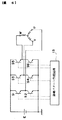
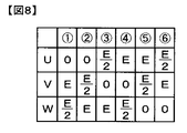
図6はドライブ回路14の一例を示す図であり、S1〜S6はトランジスタ等のスイッチング素子であり、Eは電源である。これらのスイッチング素子S1〜S6を励磁パターン作成回路13からの信号により制御して、図5に示すような電圧をステータコイルU,V,Wに印加する。図7は、図5の▲1▼〜▲6▼の1周期分について、スイッチング素子S1〜S6のオン・オフのタイミングを示したものであり、図8は各タイミングでのコイルU,V,Wの端子電圧を示したものである。
【0018】
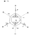
▲1▼ではスイッチング素子S1がオフ(×印)でスイッチング素子S2がオン(○印)なので、コイルUの端子電圧は0(V)となる。コイルVについてはスイッチング素子S3がオンでスイッチング素子S4がオフなので、端子電圧はE(V)となる。コイルWについてはスイッチング素子S5,S6の両方ともオフなので、コイルWの端子電圧はコイルU,Vの端子電圧の中間となり、E/2(V)である。図9は、永久磁石が設けられたロータ4,ステータコイルU,V,WおよびホールセンサHSを示す図である。図5,7,8の▲1▼のタイミングでは、電流IはコイルU,Vを図の矢印のように流れ、コイルVの側がN極、コイルUの側がS極となるような磁界が発生する。その結果、ロータ4は右回りに回転駆動される。なお、図9の場合には、ロータ4の回転基準位置は磁石30のS極の位置を指し、図9のようにS極が▲1▼の位置になったときに図5の励磁パターンの▲1▼とを一致させることにより、回転基準位置と励磁基準位置が一致する。
【0019】
また、▲2▼の場合には、スイッチング素子S3,S4の両方ともオフなのでコイルVの端子電圧はE/2(V)、スイッチング素子S5がオンでスイッチング素子S6がオフなのでコイルWの端子電圧はE(V)、コイルUは▲1▼と同じなので0(V)となる。▲3▼〜▲6▼についても同様である。上述した励磁パターン作成回路13からの信号により、このようなスイッチング素子S1〜S6のオン・オフ制御が行われ、ロータ4は右回りに連続的に回転駆動される。
【0020】
ところで、従来の装置では、図9のH1,H2,H3で示すようにホールセンサを複数設け、それらのセンサ信号(図10(a)を参照)から論理回路により励磁パターンを作成していた。例えば、図9に示す状態では図10(a)の▲1▼に示すようなセンサ信号が得られ、論理回路はこのセンサ信号に基づいて、スイッチング素子S1〜S6を図7の▲1▼のように制御する。そのため、ホールセンサH1〜H2の取り付け位置や性能自体のばらつき等により図10(a)の各センサ信号間に位相ずれが生じると、図10(b)の励磁パターンが崩れて消費電力のロスが生じる。
【0021】
しかし、上述した実施の形態では、回転センサ11で検出された回転位置とは無関係に、励磁パターン作成回路13により理想的な励磁パターンを生成しているため、励磁パターンの崩れによる消費電力のロスを防止することができる。
【0022】
図11は上述したターボ分子ポンプの変形例を示す図であり、図3に対応するものである。上述した実施の形態では、励磁パターンが理想的なものであっても、例えば、永久磁石の磁化不均一により検出した回転位置と実際の回転位置との間にずれが生じることがある。その結果、ロータ4の実際の回転基準位置と励磁パターンの対応する励磁基準位置との間に位相のずれが生じ、すなわち、ロータ4の回転とコイルU,V,Wによる回転磁界とのタイミングがずれて消費電力が増加する。
【0023】
そこで、図11に示した変形例では、ターボ分子ポンプが一定の回転速度で回転しているときに、モータ10の消費電力が最小となるように励磁パターンの位相をずらして駆動する。ところで、モータ10の消費電力は同一回転速度ではモータ電流に比例しているので、モータ電流が最小となるときに消費電力も最小となる。図11において、コントローラ15から励磁パターン作成回路13に対して励磁パターンの位相が出力され、励磁パターン作成回路13は入力された位相の励磁パターンを生成する。
【0024】
ポンプ起動当初は、励磁パターン作成回路13は、検出回路12で算出されるロータ4の回転基準位置と励磁パターンの励磁基準位置とが一致するように励磁パターンを生成する。しかし、このように駆動した場合でも、上述したように実際のロータ回転に同期しているとは限らない。コントローラ15は、励磁パターン作成回路13に入力する位相を図12のように所定の範囲H内で変動させ、モータ電流Iが最小となる位相を探す。図12はモータ電流Iと励磁パターンの位相との関係を示す図であり、縦軸はモータ電流I、横軸は回転基準位置に対する励磁基準位置の位相を示したものである。回転基準位置に対する励磁基準位置の位相をαとすると、モータ電流Iは最小値Iminとなる。このような最適位相αが求められたならば、コントローラ15は最適位相αを励磁パターン作成回路13に入力するとともに、記憶部16に格納する。その後、ターボ分子ポンプが停止された後に再び起動されたときには、記憶部16から最適位相αが呼び出され、励磁パターン作成回路13に入力される。
【0025】
上述したような最適位相αの導出は、ターボ分子ポンプが無負荷状態で一定回転のときに行われる。一般的には、ターボ分子ポンプがこのような状態にあることをオペレータが確認し、最適位相αを求めるための指令(チューニング指令)をコントローラ15に入力することにより、上述した動作(チューニング動作)が行われる
【0026】
上述した変形例では、ターボ分子ポンプはモータ電流Iが最小となるように駆動されるため、モータ消費電力が最小となり、モータ10の発熱を抑えることができる。その結果、モータ発熱によるロータ4の温度上昇を抑えることができ、ターボ分子ポンプの信頼性を向上させることができる。また、従来のように、3つのホールセンサH1〜H3の信号から励磁パターンを作成しているわけではないので、回転センサ11は複数設ける必要が無く、コスト低減が図れる。
【0027】
なお、上述した実施の形態では、ターボ分子ポンプを例に説明したが、これに限らず、DCブラシレスモータを上述したように制御することにより、モータ消費電力を従来より低減することができる。
【0028】
以上説明した実施の形態と特許請求の範囲の要素との対応において、負荷電流検出手段はドライブ回路14に対応し、最適位相検出指令はチューニング指令に対応し、最適位相検出手段はコントローラ15に対応し、位相情報記憶手段は記憶部16に対応し、駆動手段は励磁パターン作成回路13およびドライブ回路14に対応する。
【0029】
【発明の効果】
以上説明したように、本発明を適用したターボ分子ポンプによれば、外部から供給される最適位相検出指令に応答して検出された最適励磁位相を位相情報として記憶し、その後のターボ分子ポンプの稼働時には、位相情報記憶手段に記憶されている最適位相情報に基づいて励磁パターンを形成することによりDCブラシレスモータを駆動するため、モータ消費電力の低減を図ることができ、モータの不要な発熱を防止することができる。
【図面の簡単な説明】
【図1】本発明による磁気軸受式ターボ分子ポンプの概略構成を示すブロック図。
【図2】ターボ分子ポンプ本体1の詳細を示す断面図。
【図3】モータ部6およびインバータ部7の詳細図。
【図4】ロータ位置検出を説明する図であり、(a)はロータ4の永久磁石30とホールセンサHSを示す断面図であり、(b)は(a)の状態から角度aだけ回転した状態を示し、(c)は(a)の状態から角度bだけ回転した状態を示す。
【図5】ステータコイルU,V,Wに印加される電圧パターンを示す図。
【図6】ドライブ回路14の一例を示す図。
【図7】スイッチング素子S1〜S6のオン・オフのタイミングを示す図。
【図8】図7の各タイミングにおける、コイルU,V,Wの端子電圧を示す図。
【図9】ロータ4とコイルU,V,Wとの関係を示す図。
【図10】従来の装置を説明する図であり、(a)はホールセンサ信号を、(b)は励磁パターンをそれぞれ示す。
【図11】変形例を示す図。
【図12】モータ電流Iと励磁パターンの位相との関係を示す図。
【符号の説明】
1 ポンプ本体
4 ロータ
6 モータ部
7 インバータ部
10 DCブラシレスモータ
11 回転センサ
12 検出回路
13 励磁パターン作成回路
14 ドライブ回路
U,V,W ステータコイル[0001]
BACKGROUND OF THE INVENTION
The present invention relates to a turbo molecular pump.
[0002]
[Prior art]
There is a turbo molecular pump as one of vacuum pumps used in semiconductor manufacturing equipment, etc. In the turbo molecular pump, the rotor on which the rotor blades are formed is rotated by a motor, and the rotor blades are rotated at high speed with respect to the fixed blades. This exhausts gas molecules. A DC brushless motor is known as a motor for rotating the rotor. In a DC brushless motor, a plurality of hall sensors that detect the rotor magnetic poles and detect the rotational position of the rotor are provided in the stator, and an excitation pattern for exciting the stator coil by a logic circuit from each hall sensor signal is provided. Then, the motor is driven by controlling the motor drive circuit according to the excitation pattern.
[0003]
For example, three hall sensors H1, H2, and H3 are provided corresponding to three-phase (U, V, W) stator coils, and excitation voltages synchronized with the rotation period of the rotor based on signals from these three hall sensors. Is applied to each coil U, V, W. (A) of FIG. 10 is a figure which shows the sensor signal from each Hall sensor H1-H3. An excitation pattern signal is generated from the sensor signal by a logic circuit, the motor drive circuit is controlled by the signal, and excitation voltages as shown in FIG. 10B are applied to the stator coils U, V, and W.
[0004]
[Problems to be solved by the invention]
However, there has been a problem that the excitation voltage applied to the stator coil is not necessarily optimum for the following reasons.
(A) The excitation pattern deviates from the optimum one due to the phase shift of the sensor signal that occurs until the sensor signal of the Hall sensor is taken into the excitation pattern forming circuit. In particular, when a photocoupler is used in the signal path, a phase shift caused by the response time of the photocoupler occurs.
(B) Since the Hall sensor is an analog element that detects a magnetic force and inverts a signal as shown in FIG. 10A, a phase shift occurs due to element variations.
(C) Further, when the magnetization of the magnet is non-uniform, there is a shift in the rise and fall where the signal is inverted.
[0005]
If a phase shift occurs in the sensor signal due to the above-described reasons, this phase shift becomes a phase shift of the excitation pattern, and the motor drive state shifts from the optimum state. As a result, unnecessary power is consumed, which causes a temperature rise of the pump body. In particular, in the case of a magnetic bearing type turbo molecular pump, since the rotor floats in a non-contact manner in a vacuum, there is no escape of heat and the temperature is likely to rise even with a slight increase in power consumption. For example, if the power consumption is 70 to 80 W during no-load rotation but increases by 10 W due to the above-described reasons, the rotor temperature rises by 5 to 10 ° C.
[0006]
In the turbo molecular pump, since the rotor rotates at a very high speed, generally, when the temperature of the rotor made of an aluminum alloy rises, there is a problem that the strength of the rotor is reduced due to high temperature creep.
[0007]
An object of the present invention is to provide a turbo-molecular pump using the DC brushless motor capable of reducing power consumption.
[0008]
According to a first aspect of the present invention, there is provided a turbo molecular pump that rotates a rotating blade at a high speed with respect to a fixed blade by a DC brushless motor, wherein a load current detecting unit that detects a load current flowing through the DC brushless motor, and the turbo molecular pump includes: The excitation reference position relative to the rotation reference position of the DC brushless motor is relatively changed in response to an optimum phase detection command supplied from the outside in a no-load state and maintaining a predetermined constant rotation speed. An optimum phase detecting means for detecting an optimum excitation phase at which the load current is minimized, and a phase information storage means for storing the optimum excitation phase detected by the optimum phase detecting means as optimum phase information ; , wherein the time of operation of the turbo-molecular pump, and based on the said optimal phase information stored in the phase information storage means excited By forming a pattern that has a driving means for driving the DC brushless motor. The invention described in
The invention according to
[0009]
In the section of the means for solving the above-described problems for explaining the configuration of the present invention, the drawings of the embodiments of the invention are used for easy understanding of the present invention. The form is not limited.
[0010]
DETAILED DESCRIPTION OF THE INVENTION
Hereinafter, an embodiment of the present invention will be described with reference to FIGS. FIG. 1 is a block diagram showing a schematic configuration of a magnetic bearing type turbo molecular pump. The turbo molecular pump includes a turbo molecular pump
[0011]
FIG. 2 is a cross-sectional view showing details of the turbo molecular pump
[0012]
[0013]
FIG. 3 is a diagram illustrating the
[0014]
FIG. 4 is a diagram for explaining the rotor position detection when the hall sensor HS is used as the
[0015]
Returning to FIG. 3, the excitation
[0016]
The excitation
[0017]
FIG. 6 is a diagram showing an example of the
[0018]
In {circle around (1)}, since the switching element S1 is off (x mark) and the switching element S2 is on (o mark), the terminal voltage of the coil U is 0 (V). For the coil V, since the switching element S3 is on and the switching element S4 is off, the terminal voltage is E (V). As for the coil W, since both of the switching elements S5 and S6 are off, the terminal voltage of the coil W is intermediate between the terminal voltages of the coils U and V, and is E / 2 (V). FIG. 9 is a diagram showing the
[0019]
In the case of (2), since both the switching elements S3 and S4 are off, the terminal voltage of the coil V is E / 2 (V), and since the switching element S5 is on and the switching element S6 is off, the terminal voltage of the coil W is Is E (V), and the coil U is the same as (1), so it is 0 (V). The same applies to (3) to (6). Such on / off control of the switching elements S1 to S6 is performed by the signal from the excitation
[0020]
By the way, in the conventional apparatus, as shown by H1, H2, and H3 in FIG. 9, a plurality of hall sensors are provided, and an excitation pattern is created by a logic circuit from those sensor signals (see FIG. 10A). For example, in the state shown in FIG. 9, a sensor signal as shown in (1) in FIG. 10 (a) is obtained, and the logic circuit switches the switching elements S1 to S6 based on this sensor signal as shown in (1) in FIG. To control. For this reason, if a phase shift occurs between the sensor signals in FIG. 10A due to variations in the mounting positions of the Hall sensors H1 and H2 and the performance itself, the excitation pattern in FIG. Arise.
[0021]
However, in the above-described embodiment, an ideal excitation pattern is generated by the excitation
[0022]
FIG. 11 is a view showing a modified example of the turbo molecular pump described above, and corresponds to FIG. In the above-described embodiment, even if the excitation pattern is ideal, for example, a deviation may occur between the rotational position detected due to non-uniform magnetization of the permanent magnet and the actual rotational position. As a result, a phase shift occurs between the actual rotation reference position of the
[0023]
Therefore, in the modification shown in FIG. 11, when the turbo molecular pump is rotating at a constant rotation speed, the excitation pattern phase is shifted so as to minimize the power consumption of the
[0024]
At the beginning of pump activation, the excitation
[0025]
The derivation of the optimum phase α as described above is performed when the turbo molecular pump rotates at a constant speed in a no-load state. Generally, the operator confirms that the turbo molecular pump is in such a state, and inputs the command (tuning command) for obtaining the optimum phase α to the
In the above-described modification, the turbo molecular pump is driven so that the motor current I is minimized, so that the motor power consumption is minimized and the heat generation of the
[0027]
In the above-described embodiment, the turbo molecular pump has been described as an example. However, the present invention is not limited to this, and by controlling the DC brushless motor as described above, the motor power consumption can be reduced as compared with the related art.
[0028]
In the correspondence between the embodiment described above and the elements of the claims, the load current detection means corresponds to the
[0029]
【The invention's effect】
As described above, according to the turbo molecular pump to which the present invention is applied, the optimum excitation phase detected in response to the optimum phase detection command supplied from the outside is stored as phase information, and the subsequent turbo molecular pump During operation, the DC brushless motor is driven by forming an excitation pattern based on the optimum phase information stored in the phase information storage means, so that motor power consumption can be reduced, and unnecessary heat generation of the motor can be achieved. Can be prevented.
[Brief description of the drawings]
FIG. 1 is a block diagram showing a schematic configuration of a magnetic bearing turbomolecular pump according to the present invention.
FIG. 2 is a cross-sectional view showing details of a turbo molecular pump
3 is a detailed view of a
4A and 4B are diagrams for explaining rotor position detection, in which FIG. 4A is a cross-sectional view showing a
FIG. 5 is a diagram showing voltage patterns applied to stator coils U, V, and W.
6 is a diagram showing an example of a
FIG. 7 is a diagram showing on / off timings of switching elements S1 to S6.
8 is a diagram showing terminal voltages of coils U, V, and W at each timing of FIG. 7;
FIG. 9 is a diagram showing a relationship between a
10A and 10B are diagrams for explaining a conventional device, in which FIG. 10A shows a Hall sensor signal, and FIG. 10B shows an excitation pattern.
FIG. 11 is a diagram showing a modified example.
FIG. 12 is a diagram showing a relationship between a motor current I and the phase of an excitation pattern.
[Explanation of symbols]
DESCRIPTION OF
Claims (2)
前記DCブラシレスモータに流れる負荷電流を検出する負荷電流検出手段と、
前記ターボ分子ポンプが無負荷状態であって且つ所定の一定回転速度を維持しているときに外部から供給される最適位相検出指令に応答して、前記DCブラシレスモータの回転基準位置に対する励磁基準位置を相対的に変化させることにより、前記負荷電流が最小となる最適励磁位相を検出する最適位相検出手段と、
前記最適位相検出手段により検出された前記最適励磁位相を最適位相情報として記憶しておく位相情報記憶手段と、
前記ターボ分子ポンプの稼働時には、前記位相情報記憶手段に記憶されている前記最適位相情報に基づいて励磁パターンを形成することにより前記DCブラシレスモータを駆動する駆動手段とを備えることを特徴とするターボ分子ポンプ。In a turbo molecular pump that rotates a rotating blade at high speed with respect to a fixed blade by a DC brushless motor,
Load current detection means for detecting a load current flowing through the DC brushless motor;
In response to an optimum phase detection command supplied from the outside when the turbo molecular pump is in a no-load state and maintains a predetermined constant rotational speed, an excitation reference position with respect to the rotation reference position of the DC brushless motor By changing the relative phase, the optimum phase detection means for detecting the optimum excitation phase that minimizes the load current,
And phase information storage means for storing as the optimal phase information detected the optimum excitation phase by the optimum phase detecting means,
During operation of the turbo molecular pump is characterized by comprising driving means for driving the DC brushless motor by forming a based have been excitation pattern to the optimum phase information stored in the phase information storage means Turbo molecular pump.
前記DCブラシレスモータの回転基準位置は、前記DCブラシレスモータのロータに埋め込まれた永久磁石の磁気を検出する単一の磁気検出素子から出力される信号により決定されることを特徴とするターボ分子ポンプ。The turbo-molecular pump according to claim 1,
The rotational reference position of the DC brushless motor is determined by a signal output from a single magnetic detection element that detects the magnetism of a permanent magnet embedded in the rotor of the DC brushless motor. .
Priority Applications (1)
| Application Number | Priority Date | Filing Date | Title |
|---|---|---|---|
| JP2000062456A JP4419258B2 (en) | 2000-03-07 | 2000-03-07 | Turbo molecular pump |
Applications Claiming Priority (1)
| Application Number | Priority Date | Filing Date | Title |
|---|---|---|---|
| JP2000062456A JP4419258B2 (en) | 2000-03-07 | 2000-03-07 | Turbo molecular pump |
Publications (3)
| Publication Number | Publication Date |
|---|---|
| JP2001251829A JP2001251829A (en) | 2001-09-14 |
| JP2001251829A5 JP2001251829A5 (en) | 2006-07-20 |
| JP4419258B2 true JP4419258B2 (en) | 2010-02-24 |
Family
ID=18582466
Family Applications (1)
| Application Number | Title | Priority Date | Filing Date |
|---|---|---|---|
| JP2000062456A Expired - Lifetime JP4419258B2 (en) | 2000-03-07 | 2000-03-07 | Turbo molecular pump |
Country Status (1)
| Country | Link |
|---|---|
| JP (1) | JP4419258B2 (en) |
-
2000
- 2000-03-07 JP JP2000062456A patent/JP4419258B2/en not_active Expired - Lifetime
Also Published As
| Publication number | Publication date |
|---|---|
| JP2001251829A (en) | 2001-09-14 |
Similar Documents
| Publication | Publication Date | Title |
|---|---|---|
| KR100712673B1 (en) | Control circuit of brush-less motor, control circuit of sensor-less brush-less motor, brush-less motor apparatus, sensor-less brush-less motor apparatus and vacuum pump apparatus | |
| US8294397B2 (en) | Sensorless starting control method for a BLDC motor | |
| JP2005261186A (en) | Method and apparatus for controlling electronically commutated motor | |
| JP5682157B2 (en) | Motor drive device and pump system for vacuum pump | |
| KR20030074415A (en) | Vacuum pump system and method for controlling revolutions of vacuum pump | |
| JP2013079602A (en) | Turbo-molecular pump | |
| JP2011231760A (en) | Magnetic levitation vacuum pump and method of starting rotation of the same | |
| JP4511682B2 (en) | Control device for motor for compressor | |
| JP4419258B2 (en) | Turbo molecular pump | |
| JP3833918B2 (en) | Motor control device | |
| JP4645171B2 (en) | DC brushless motor device and turbo molecular pump | |
| JP2001231238A (en) | Dc brushless motor and turbo molecular pump equipped with the motor | |
| HUP0004302A2 (en) | Method for the starting and steady-state supply of a permanent-magnet synchronous motor particularly for driving a hydraulic pump | |
| JP5978924B2 (en) | Motor drive device and vacuum pump | |
| JP6801481B2 (en) | Magnetic bearing equipment and vacuum pump | |
| JP6015000B2 (en) | Vacuum pump | |
| CN111902636B (en) | Vacuum pump and control device for vacuum pump | |
| EP1489321A1 (en) | Motor control system, motor apparatus, vacuum pump, correction current value measuring apparatus, and motor control method | |
| JP2012193705A (en) | Vacuum pump and rotation-starting method thereof | |
| JPH06253523A (en) | Dc brushless motor and turbo molecular pump employing it | |
| JP2007082370A (en) | Dc brushless motor apparatus and rotary vacuum pump | |
| JP2009092047A (en) | Vacuum pump device and phase difference detection method | |
| JP2006014388A (en) | Inverter controller | |
| JP2020162345A (en) | Electric motor system | |
| JP7456138B2 (en) | Vacuum pump |
Legal Events
| Date | Code | Title | Description |
|---|---|---|---|
| A521 | Written amendment |
Free format text: JAPANESE INTERMEDIATE CODE: A523 Effective date: 20060606 |
|
| A621 | Written request for application examination |
Free format text: JAPANESE INTERMEDIATE CODE: A621 Effective date: 20060606 |
|
| A977 | Report on retrieval |
Free format text: JAPANESE INTERMEDIATE CODE: A971007 Effective date: 20081127 |
|
| A131 | Notification of reasons for refusal |
Free format text: JAPANESE INTERMEDIATE CODE: A131 Effective date: 20081202 |
|
| A521 | Written amendment |
Free format text: JAPANESE INTERMEDIATE CODE: A523 Effective date: 20090202 |
|
| A131 | Notification of reasons for refusal |
Free format text: JAPANESE INTERMEDIATE CODE: A131 Effective date: 20090818 |
|
| A521 | Written amendment |
Free format text: JAPANESE INTERMEDIATE CODE: A523 Effective date: 20091016 |
|
| TRDD | Decision of grant or rejection written | ||
| A01 | Written decision to grant a patent or to grant a registration (utility model) |
Free format text: JAPANESE INTERMEDIATE CODE: A01 Effective date: 20091110 |
|
| A01 | Written decision to grant a patent or to grant a registration (utility model) |
Free format text: JAPANESE INTERMEDIATE CODE: A01 |
|
| A61 | First payment of annual fees (during grant procedure) |
Free format text: JAPANESE INTERMEDIATE CODE: A61 Effective date: 20091123 |
|
| FPAY | Renewal fee payment (event date is renewal date of database) |
Free format text: PAYMENT UNTIL: 20121211 Year of fee payment: 3 |
|
| R151 | Written notification of patent or utility model registration |
Ref document number: 4419258 Country of ref document: JP Free format text: JAPANESE INTERMEDIATE CODE: R151 |
|
| FPAY | Renewal fee payment (event date is renewal date of database) |
Free format text: PAYMENT UNTIL: 20121211 Year of fee payment: 3 |
|
| FPAY | Renewal fee payment (event date is renewal date of database) |
Free format text: PAYMENT UNTIL: 20121211 Year of fee payment: 3 |
|
| FPAY | Renewal fee payment (event date is renewal date of database) |
Free format text: PAYMENT UNTIL: 20131211 Year of fee payment: 4 |
|
| EXPY | Cancellation because of completion of term |