JP4416405B2 - Ultrasonic molding equipment - Google Patents
Ultrasonic molding equipment Download PDFInfo
- Publication number
- JP4416405B2 JP4416405B2 JP2002590844A JP2002590844A JP4416405B2 JP 4416405 B2 JP4416405 B2 JP 4416405B2 JP 2002590844 A JP2002590844 A JP 2002590844A JP 2002590844 A JP2002590844 A JP 2002590844A JP 4416405 B2 JP4416405 B2 JP 4416405B2
- Authority
- JP
- Japan
- Prior art keywords
- frequency
- sonotrode
- instrument
- head
- control unit
- Prior art date
- Legal status (The legal status is an assumption and is not a legal conclusion. Google has not performed a legal analysis and makes no representation as to the accuracy of the status listed.)
- Expired - Fee Related
Links
- 238000000465 moulding Methods 0.000 title claims description 9
- 238000007906 compression Methods 0.000 claims abstract description 6
- 238000004804 winding Methods 0.000 claims description 6
- 230000006835 compression Effects 0.000 claims description 5
- 230000003247 decreasing effect Effects 0.000 claims description 2
- 238000007493 shaping process Methods 0.000 abstract 2
- 230000006870 function Effects 0.000 description 7
- 208000006558 Dental Calculus Diseases 0.000 description 3
- RTAQQCXQSZGOHL-UHFFFAOYSA-N Titanium Chemical compound [Ti] RTAQQCXQSZGOHL-UHFFFAOYSA-N 0.000 description 3
- 239000004020 conductor Substances 0.000 description 3
- 230000000694 effects Effects 0.000 description 3
- 239000000463 material Substances 0.000 description 3
- 238000001228 spectrum Methods 0.000 description 3
- 239000010936 titanium Substances 0.000 description 3
- 229910052719 titanium Inorganic materials 0.000 description 3
- 238000005452 bending Methods 0.000 description 2
- 238000007790 scraping Methods 0.000 description 2
- 238000004590 computer program Methods 0.000 description 1
- 238000005520 cutting process Methods 0.000 description 1
- 230000007423 decrease Effects 0.000 description 1
- 210000003298 dental enamel Anatomy 0.000 description 1
- 238000010586 diagram Methods 0.000 description 1
- 238000005516 engineering process Methods 0.000 description 1
- 238000005530 etching Methods 0.000 description 1
- 238000007689 inspection Methods 0.000 description 1
- 238000012423 maintenance Methods 0.000 description 1
- 238000004519 manufacturing process Methods 0.000 description 1
- 230000008018 melting Effects 0.000 description 1
- 238000002844 melting Methods 0.000 description 1
- 229910052751 metal Inorganic materials 0.000 description 1
- 239000002184 metal Substances 0.000 description 1
- 238000012986 modification Methods 0.000 description 1
- 230000004048 modification Effects 0.000 description 1
- 230000005405 multipole Effects 0.000 description 1
- 239000012858 resilient material Substances 0.000 description 1
- 238000004513 sizing Methods 0.000 description 1
- 229910001220 stainless steel Inorganic materials 0.000 description 1
- 239000010935 stainless steel Substances 0.000 description 1
- 229920002994 synthetic fiber Polymers 0.000 description 1
- 238000003466 welding Methods 0.000 description 1
Images

Classifications
-
- A—HUMAN NECESSITIES
- A61—MEDICAL OR VETERINARY SCIENCE; HYGIENE
- A61C—DENTISTRY; APPARATUS OR METHODS FOR ORAL OR DENTAL HYGIENE
- A61C17/00—Devices for cleaning, polishing, rinsing or drying teeth, teeth cavities or prostheses; Saliva removers; Dental appliances for receiving spittle
- A61C17/16—Power-driven cleaning or polishing devices
- A61C17/20—Power-driven cleaning or polishing devices using ultrasonics
-
- B—PERFORMING OPERATIONS; TRANSPORTING
- B06—GENERATING OR TRANSMITTING MECHANICAL VIBRATIONS IN GENERAL
- B06B—METHODS OR APPARATUS FOR GENERATING OR TRANSMITTING MECHANICAL VIBRATIONS OF INFRASONIC, SONIC, OR ULTRASONIC FREQUENCY, e.g. FOR PERFORMING MECHANICAL WORK IN GENERAL
- B06B1/00—Methods or apparatus for generating mechanical vibrations of infrasonic, sonic, or ultrasonic frequency
- B06B1/02—Methods or apparatus for generating mechanical vibrations of infrasonic, sonic, or ultrasonic frequency making use of electrical energy
- B06B1/0207—Driving circuits
- B06B1/0223—Driving circuits for generating signals continuous in time
- B06B1/0269—Driving circuits for generating signals continuous in time for generating multiple frequencies
- B06B1/0284—Driving circuits for generating signals continuous in time for generating multiple frequencies with consecutive, i.e. sequential generation, e.g. with frequency sweep
-
- B—PERFORMING OPERATIONS; TRANSPORTING
- B06—GENERATING OR TRANSMITTING MECHANICAL VIBRATIONS IN GENERAL
- B06B—METHODS OR APPARATUS FOR GENERATING OR TRANSMITTING MECHANICAL VIBRATIONS OF INFRASONIC, SONIC, OR ULTRASONIC FREQUENCY, e.g. FOR PERFORMING MECHANICAL WORK IN GENERAL
- B06B2201/00—Indexing scheme associated with B06B1/0207 for details covered by B06B1/0207 but not provided for in any of its subgroups
- B06B2201/50—Application to a particular transducer type
- B06B2201/55—Piezoelectric transducer
-
- B—PERFORMING OPERATIONS; TRANSPORTING
- B06—GENERATING OR TRANSMITTING MECHANICAL VIBRATIONS IN GENERAL
- B06B—METHODS OR APPARATUS FOR GENERATING OR TRANSMITTING MECHANICAL VIBRATIONS OF INFRASONIC, SONIC, OR ULTRASONIC FREQUENCY, e.g. FOR PERFORMING MECHANICAL WORK IN GENERAL
- B06B2201/00—Indexing scheme associated with B06B1/0207 for details covered by B06B1/0207 but not provided for in any of its subgroups
- B06B2201/70—Specific application
- B06B2201/76—Medical, dental
Landscapes
- Health & Medical Sciences (AREA)
- Dentistry (AREA)
- Epidemiology (AREA)
- Life Sciences & Earth Sciences (AREA)
- Animal Behavior & Ethology (AREA)
- General Health & Medical Sciences (AREA)
- Public Health (AREA)
- Veterinary Medicine (AREA)
- Engineering & Computer Science (AREA)
- Mechanical Engineering (AREA)
- Dental Tools And Instruments Or Auxiliary Dental Instruments (AREA)
- Apparatuses For Generation Of Mechanical Vibrations (AREA)
- Surgical Instruments (AREA)
Abstract
Description
本発明は
・取り付け構造体、
・前記取り付け構造体に弾力的に取り付けられたソノトロード(sonotrode)、
・成形作業を行うために前記ソノトロードに固定された器具、
・前記ソノトロードを制御し、電力を与える制御ユニット
を有する型の超音波成形機器に関する。
The present invention provides a mounting structure,
A sonotrode elastically attached to the mounting structure,
An instrument fixed to the sonotrode to perform the molding operation,
The present invention relates to an ultrasonic molding apparatus having a control unit that controls the sonotrode and provides electric power.
「成形」とは、物の機械的な除去又は溶融によって対象物の構造を変更しようとする全ての機械的操作を意味する。 “Molding” means any mechanical operation that attempts to change the structure of an object by mechanical removal or melting of the object.
この型の機器は、例えば、WO特許第89/01763に開示されている。この機器は、超音波周波数での低振幅の動きによって作動される掻き取り具によって歯石を破壊し、歯から歯石を除去するためのものである。制御ユニットは増幅器型の回路であって、ソノトロードに連結されて機器の特徴によって決定される周波数を有する発振機を形成する。この周波数は、特に、機器が操作されるとジュール効果によって上昇する温度と共に変化する。 This type of device is disclosed, for example, in WO patent 89/01763. This device is intended to destroy tartar and remove tartar from teeth with a scraper activated by low amplitude movement at ultrasonic frequencies. The control unit is an amplifier type circuit and is connected to the sonotrode to form an oscillator having a frequency determined by the characteristics of the device. This frequency changes with increasing temperature, especially due to the Joule effect when the device is operated.
増幅器型の回路を使用すると、満足の行く作動条件が提供される。しかしながら、増幅器型の回路は比較的高価で、使用可能な容量を考慮すると、使用に際しての電力が大きくなると、より一層高価になる。 Use of an amplifier type circuit provides satisfactory operating conditions. However, amplifier-type circuits are relatively expensive, and considering the capacity that can be used, the higher the power in use, the higher the cost.
本発明の目的は、機器の特徴の関数としては変動しない信号を変換器の端子に与えるように設計された、単純化された制御ユニットの使用を可能にすることである。その結果、機器はサーボシステムを有する必要がもはや無く、機器の単純化及び小型化を実現することができる。 It is an object of the present invention to allow the use of a simplified control unit designed to provide a signal at the converter terminal that does not vary as a function of equipment characteristics. As a result, the device no longer needs to have a servo system and simplification and miniaturization of the device can be realized.
この目的は、この機器が次のように構成されているという事実によって達成することができる。
・ソノトロードと器具によって形成されている組立体が、牽引圧縮及びねじれから選択されるモードにおいて、下限fominから上限fomaxへと変化させることのできる超音波共鳴周波数foを有し、
・前記組立体が、周波数fpmin<fominと周波数fpmax>fomaxとの間で他の共鳴周波数を有さず、
制御ユニットは、準ランダム信号によって周波数変調される正弦波信号を発生して最小周波数feminと最大周波数femaxとの間の電気通過帯域信号を印加することができるようにした型のものである(ここで、feminはfpminとfominとの間の周波数であり、femaxはfomaxとfpmaxとの間の周波数である。)。
This object can be achieved by the fact that this device is configured as follows.
The assembly formed by the sonotrode and the instrument has an ultrasonic resonance frequency fo that can be changed from the lower limit Fomin to the upper limit fomax in a mode selected from traction compression and torsion;
The assembly does not have any other resonant frequency between the frequency fpmin <fomin and the frequency fpmax>fomax;
The control unit is of a type that is capable of generating a sinusoidal signal that is frequency modulated by a quasi-random signal and applying an electrical passband signal between the minimum frequency femin and the maximum frequency femax (here. Femin is a frequency between fpmin and fomin, and femax is a frequency between fomax and fpmax.)
「準ランダム信号」は、例えば、シフトレジスタによってコンピュータプログラムが発生することのできるもののような、ランダム信号又は擬似ランダム信号を意味する。自然周波数foは周波数のスペクトルとして考慮されるのがよく、その最大値はfoである。このスペクトルの幅は実質的にソノトロードの構造と作動条件との関数である。考慮されている範囲でfo以外の共鳴周波数がないというのは相対的な意味において理解されるべきである。実際には、考慮されている周波数foでのエネルギーレベルとfpminからfpmaxの範囲の残りの範囲におけるエネルギーレベルとの間の比が4:1であれば、許容可能な作動条件を得るのに既に十分である。 By “quasi-random signal” is meant a random signal or a pseudo-random signal, such as one that can be generated by a computer program with a shift register, for example. The natural frequency fo should be considered as a frequency spectrum, and its maximum value is fo. The width of this spectrum is substantially a function of the sonotrode structure and operating conditions. It should be understood in a relative sense that there is no resonance frequency other than fo in the range considered. In practice, if the ratio between the energy level at the considered frequency fo and the energy level in the remaining range of fpmin to fpmax is 4: 1, it is already possible to obtain an acceptable operating condition. It is enough.
前記のような機器については、ソノトロードは、その時点での自然周波数に対応する信号成分によって動力が与えられる。したがって、fominとfomaxとの間の周波数は、feminとfemaxとの間にあるので、機器の操作範囲全体において維持することができる。さらに、feminとfemaxとの間の周波数を含むfpminとfpmaxとの間に他の共鳴周波数がないので、漂遊周波数で機器が発振を始める危険性がない。機器が漂遊周波数で発振すると、効率を低減し、連続動作を妨げ得る程度の発熱が生じることがある。 For such devices, the sonotrode is powered by a signal component corresponding to the current natural frequency. Therefore, since the frequency between fomin and fomax is between femin and femax, it can be maintained over the entire operating range of the device. Furthermore, since there is no other resonance frequency between fpmin and fpmax including the frequency between femin and femax, there is no risk that the device will start oscillating at the stray frequency. When the device oscillates at stray frequencies, it may generate heat that can reduce efficiency and hinder continuous operation.
この機器においては、制御ユニットはE級増幅回路で形成された電力回路、及び該電力回路を駆動する制御回路を含むことができ、ソノトロードは圧電型変換器を含むことができる。より詳しくは、前記電力回路は電力用トランジスタと変圧器とを有し、該変圧器の一次巻線は前記トランジスタに接続されており、二次巻線は前記圧電型変換器に接続されている。 In this device, the control unit can include a power circuit formed of a class E amplifier circuit and a control circuit that drives the power circuit, and the sonotrode can include a piezoelectric transducer. More specifically, the power circuit includes a power transistor and a transformer, a primary winding of the transformer is connected to the transistor, and a secondary winding is connected to the piezoelectric transducer. .
使用状態に応じて器具に与える電力を変化させる必要がある。これは、制御ユニットがfemin及び/又はfemaxの値を変えることによって容易に達成することができる。feminとfemaxとの間隔が増加するに従って、考慮されている周波数foが使用することのできる電力は減少する。より正確には、使用することのできる電力は、帯域幅の変化に反比例する。 It is necessary to change the power applied to the appliance according to the state of use. This can easily be achieved by the control unit changing the value of femin and / or femax. As the distance between femin and femax increases, the power available for the considered frequency fo decreases. More precisely, the power that can be used is inversely proportional to the change in bandwidth.
ソノトロードが圧縮モードで動作し、その周波数が20 kHzよりも高いと好ましい。 Sonotrode operates in compressed mode, preferably the frequency is higher than 20 kHz.
機器を手で扱えるようにするために、その取り付け構造体は、内側にソノトロードを搭載したスリーブで形成される。 In order to be able to handle the device by hand, its mounting structure is formed by a sleeve with a sonotrode mounted inside.
ソノトロードが最適に動作する条件を保証するために、ソノトロードは慣性質量体とヘッドとを有する。一方が前記質量体と協働し、他方が前記ヘッドと協働する2つの弾性部材によってソノトロードは前記スリーブに取り付けられ、器具はヘッドにしっかりと固定されている。前記圧電型変換器は前記ヘッドと質量体との間に挿入される。 In order to ensure that the sonotrode operates optimally, the sonotrode has an inertial mass and a head. The sonotrode is attached to the sleeve by two elastic members, one cooperating with the mass and the other cooperating with the head, and the instrument is firmly fixed to the head. The piezoelectric transducer is inserted between the head and the mass body.
これらの機器によって、特に、前記器具が歯から歯石を除去するのに適した掻き取り具の形状をしていると、掻き取りによる成形を行うことができる。 With these devices, in particular, if the appliance is in the form of a scraper suitable for removing tartar from the teeth, it is possible to perform molding by scraping.
本発明の他の特徴及び効果は、添付の図面を参照してなされる以下の記載から明らかになろう。 Other features and advantages of the present invention will become apparent from the following description made with reference to the accompanying drawings.
図1に示されている機器は歯から歯垢を除去するためのものである。この機器は、スリーブ10、該スリーブ中に収容された制御ユニット12(これについては、図2を参照して詳述する)、ソノトロード14、及び螺子によって前記ソノトロード14にしっかりと取り付けられると共にスリーブ10の外側に配された掻き取り具16を形成する器具を実質的に有している。制御ユニット12は、スリーブ10の端部の一方に接続されているケーブル18によって、図示されない電気エネルギー源から電力を供給される。
The device shown in FIG. 1 is for removing plaque from teeth. The device is secured to the
スリーブ10は、軸A−Aを有する、ステンレススチール又は合成材料によって作られた実質的に柱状の管によって形成されている。その端部の1つ10aは、制御ユニット12をスリーブ10の内側に保持すると共にケーブル18が通り抜けている環状キャップ20によって部分的に閉鎖されている。他端10bは開口部を有しており、掻き取り具16を有するソノトロード14の端部がそこに嵌合している。スリーブ10は一体に作られていてもよく、また、相互に協働し、螺子又は溶接によって相互に固定された複数の環から形成されていてもよい。複数の環を使用すると、制御ユニット12及びソノトロード14の配置が容易になる。
The
その端部10bに隣接する位置に、スリーブ10は掻き取り具16の駆動に使用する電力を調整する制御環22と、長手方向に動くことができて機器のスイッチのオン/オフを制御するボタン24とを有している。
At a position adjacent to the
制御環22は環状多極磁石26を備えており、スリーブ10の内側に固定されると共に導線30によって制御ユニット12に電気的に接続されている磁気感応性接触器28を制御する。制御環22と接触器28とは、制御環22の回転方向が制御ユニット12によって認識されるように配されている。
The control ring 22 includes an
ボタン24は、やはりスリーブ10に搭載され、導線34によって制御ユニット12に接続されたスイッチ34を制御して、掻き取り具16を動かし始めるソノトロード14の電力のオン/オフを制御する。
The
ソノトロード14は、慣性質量体36、ヘッド38、及びヘッド38と慣性質量体36との間に挿入された圧電型変換器40を有する。ソノトロード14は、弾力性のある材料によって作られ、溝44にはめ込まれた2つのOリングによって、スリーブ10内に弾力的に取り付けられる。溝44の1つはヘッド38に形成され、もう1つは慣性質量体36に形成され、スリーブ10に隣接している。
The
慣性質量体36は、圧電型変換器によって生成された動きが実質的に掻き取り具16に与えられて機器の他の部分が動かないように、手で機器を適切に保持するのが可能である許容範囲内で可能な限り重くなるように選択される。慣性質量体は、変換器40が取り付けられた棒36aによって、ヘッド38の方向に延びており、その端部には内部螺子筋36bが切られている。
The
ヘッド38は略カニューレ形をしており、棒36a上に螺合されると共に溝44が設けられている変換器40に近接する環38aを有している。環38aは、中をチャネル38cが貫通している管38bにつながって延びている。管38bの前記環と反対側の端部には螺子筋38dが設けられており、その上に掻き取り具16が固定されている。
The
穴部38cは、ヘッドの共鳴周波数を調節する機能を有している。穴部38cの直径と管38bの壁厚は、機器の様々な動作部品の一般形状の関数として、経験的に選択される。実際、穴部の直径を変更することによって、圧縮モード、ねじれモード又は曲げモードの共鳴周波数を異なった方法で変更する。このように、穴部38cの直径と管38bの厚さを操作することによって、これらの共鳴周波数をオフセットすることが可能である。
The
ヘッド38は、内部摩擦を最小にしつつその慣性が可能な限り低くなるように、例えば、チタンなどの軽金属で形成されていると都合がよい。
The
ヘッド38の形状は、掻き取り具16の動きが可能な限り広くなるように選択される。この点に関する検討は国際公開公報WO No. 89/01763号でなされており、この文献をここで引用する。したがって、これらについては本明細書中では詳細に説明しない。
The shape of the
変換器40は、例えば、フィリップス(アインドホーヴェン エヌエル)(Philips (Eindhovel NL))によって参照番号4322 020 0659で販売されている材料などの圧電材料から作られる4つのディスク50によって形成されている。これらのディスク50は、外径が10 mm、中央開口部の直径が5mm、厚さが2mmである。2つの平坦な面は導電性材料の層で被覆されており、電極の機能を有している。例えば、国際公開公報WO No. 89/01763号に記載されているように、ディスク50は並列に接続されており、さらに、一方では電気的アースによって、他方では導線52によって制御ユニット12に接続されている。通常、圧電型変換器は圧縮モードで動作する。しかしながら、ねじれモードで動作させることも可能である。剪断モードには適用することができないようである。
The
ディスク50が圧電効果によって圧縮されても、ディスクと質量体36及びヘッド38との間に遊びが生じないように、ヘッド38は質量体36に螺子止めされて圧電ディスク50に予備ストレスを与えている。
Even if the
掻き取り具16は、ヘッド38の端部38dに固定されており、この固定のために螺子筋を切った穴を有する部分16aと、成形機能を実行するための動作部16bとを有している。動作部16bを形成する材料は、処理を受ける歯に堆積している歯垢を攻撃するのに十分な程度に硬くなくてはならないが、エナメル質を傷つけるのを避けるために硬すぎてはならない。
The
ソノトロードの部品全部とそれに取り付けられている掻き取り具16との特徴によって、その自然周波数foが決定される。この周波数は一般に20kHzよりも高く、通常、25kHzである。この周波数は、特に動作温度と掻き取り具に加えられる負荷の関数として、fominとfomaxとの間で変動することがある。この変動は±1%のオーダーである。
The natural frequency fo is determined by the characteristics of all the parts of the sonotrode and the
以下の特徴を有するソノトロードで試験が行われた。チタン製の慣性質量態36は30mmに等しい全長を有し、棒36aは長さ12.5mm、直径4.2mmである。この質量体全体は長さ16mmに亘って軸方向に孔が設けられており、質量体の直径が最も大きい位置で孔の直径は2mm、棒36aの部分では1mmである。ヘッド38もチタンで作られている。環38aは、直径が10mmで長さが実質的に3mmである円筒状の部分を有している。管38bは、直径が4mm、長さが実質的に20mm、壁厚が0.4mmである。端部38dは長さが6mmで、その内の4.5mmは螺子筋が切ってある。この端部には直径1mmの孔が設けられている。得られた装置は、圧縮モード共鳴周波数が24.3kHzであり、漂遊曲げモード周波数が21.2kHzと35.2kHzであり、それらの振幅は、周波数foにおける振幅のそれぞれ1/3と1/9である。
Tests were conducted on a sonotrode having the following characteristics: The
この例で得られた周波数を以下の表に記載する。 The frequencies obtained in this example are listed in the table below.

このように、feminとfemaxとが変化することのできる範囲が広いので、掻き取り具16に与えられる動力を調節する範囲が広くなる。
Thus, since the range in which femin and femax can change is wide, the range in which the power applied to the
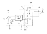
制御ユニット12が図2に示されている。制御ユニットはソノトロード14に電力を供給する電力回路54と、電力回路54を駆動する制御回路56とを有する。
A
電力回路54はE級増幅回路である。この回路は、ミュンヘン(ドイツ)のインフィネオン・テクノロジーズ(Infineon Technologies)によって市販されているものなどのBUZ11型の電力用トランジスタ58、及び変圧器60を有している。この変圧器の一次巻線は電力源VDDとトランジスタ58とに接続されており、一方、二次巻線は変換器40の端子に接続されている。変圧器60は、変換器40の端子にかかる電圧が歯垢除去操作に必要な電力を与えるのに十分であるように容量設計される。実地試験によって、400Vのオーダーの有効電圧で十分であることが示されている。
The
制御回路56は、例えば、アリゾナ州(米国)のマイクロチップ・チャンドラー(Microcip Chandler)によって販売されているPIC 12 Cxxx型などのマイクロプロセッサ62と共に接触器28とスイッチ32とを有する。
The
マイクロプロセッサ62は、接触器28とスイッチ32の状態に関するデータとその操作プログラムを含むメモリを備えている。
The
マイクロプロセッサ62の仕事はスイッチ32の状態を検出することである。スイッチが開の時は、他のプログラムは待機状態となる。
The task of the
スイッチ32が閉じられると、マイクロプロセッサ62は接触器28からのデータを求めてメモリを探す。このようなデータは、環22をある方向、又は反対方向に回転させることによって変更することができ、それによって、メモリの内容を増加又は減少させる。このデータから、マイクロプロセッサ62は、その周波数femoyがソノトロード14の共鳴周波数foに近いキャリア信号と、モトローラのMcMOSハンドブック(1974)のセクションEに説明されているように、シフトレジスタの使用によって擬雑音を発生する。最小周波数feminと最大周波数femaxとによって限定される擬雑音の帯域幅は、メモリの内容が大きいほど広くなる。
When
擬雑音によって変調された信号は、パルスの形態でトランジスタ58のグリッド58aに印加され、その電流はトランジスタ58によって増幅され、電圧は変圧器60によって増幅される。ソノトロード14は、その共鳴スペクトルと同時に発生する信号の一部によって電力を供給される。その結果、与えられる電力が大きくなると、feminとfemaxとによって限定される帯域が狭くなる。このように、femin及び/又はfemaxを変化させることによって、ソノトロード14から掻き取り具16に与えられる電力を調節することが可能になる。
The signal modulated by the pseudo-noise is applied to the grid 58a of the
このような制御によって、fominとfomaxとがfeminとfemaxとの間に入っていれば、ソノトロードの自然周波数foが変化しても、マイクロプロセッサから得られる信号は同じにすることができる。 With such control, if fomin and fomax are between femin and femax, even if the natural frequency fo of the sonotrode changes, the signal obtained from the microprocessor can be made the same.
その結果、非常に単純な制御ユニットについて記載されるように、機器のメンテナンスを行うことができる。しかしながら、特に注意をしなくてはならない点がある。それは、もし、機器がfeminとfemaxとの間に1以上の自然周波数を有していると、機器は振動してエネルギーが散逸して純粋に浪費され、さらに、機器が加熱される。この問題は、fpmin<feminとfpmax>femaxとの間の範囲内に他の共鳴周波数を有さないように機器の部品を調節することにより、回避することができる。 As a result, maintenance of the equipment can be performed as described for a very simple control unit. However, there are points that require special attention. That is, if the device has a natural frequency of 1 or more between femin and femax, the device will vibrate and dissipate energy and is wasted purely, and the device is heated. This problem can be avoided by adjusting the components of the instrument so that it does not have other resonance frequencies in the range between fpmin <femin and fpmax> femax.
この要求を満たすために、機器はできるだけ硬く、この目的を達成するように様々な部品の大きさを調節するのが望ましい。 To meet this requirement, the equipment is as hard as possible and it is desirable to adjust the size of the various parts to achieve this goal.
実際、様々な部品はこの剛性が得られるように寸法設定され、次いで、ソノトロードが共鳴周波数を示すように可変周波数信号によって電力供給される。その寸法が機器の特徴に適した周波数を得られるように調整され、一方、漂遊周波数が除去される。この寸法設定作業は、ソノトロードの慣性を実質的に質量体36及びヘッド38で修正するか、実質的に棒48によって形成されているその弾性構造体を調節して、試行錯誤で行われる。
In fact, the various components are sized to obtain this stiffness and then powered by a variable frequency signal so that the sonotrode exhibits a resonant frequency. Its dimensions are adjusted to obtain a frequency suitable for the characteristics of the instrument, while stray frequencies are eliminated. This sizing operation is done on a trial and error basis, so that the inertia of the sonotrode is substantially corrected by the
実施試験では、機器の構成部品は十分に精巧であり、その自然周波数が機器によって変わることは実質的にないことが示された。しかしながら、特に漂遊共鳴周波数が周波数fpmin及びfpmaxの一方又は他方に近い場合は、製造終了後の検査を行うことが望ましい。 Implementation tests have shown that the instrument components are sophisticated enough that their natural frequency does not vary from instrument to instrument. However, in particular, when the stray resonance frequency is close to one or the other of the frequencies fpmin and fpmax, it is desirable to perform an inspection after the end of production.
本発明の範囲から離れることなく、ここに記載した機器に数多くの変更を加えることができるのは明らかである。したがって、このような機器を、ばり取り、切削もしくはエッチング作業、又は超音波マイクロ溶接を行うのにすら使用することが可能である。これら応用の各々において、機器の漂遊周波数に与える影響を考慮しつつ、機器を成形操作に使用する。 Obviously, numerous modifications can be made to the device described herein without departing from the scope of the invention. Thus, such equipment can be used even for deburring, cutting or etching operations, or even ultrasonic microwelding. In each of these applications, the device is used for the molding operation, taking into account the effect on the stray frequency of the device.
Claims (10)
・前記取り付け構造体(10)に弾力的に取り付けられたソノトロード(14)、
・成形作業を行うために前記ソノトロード(14)に固定された器具(16)、
・前記ソノトロード(14)を制御し、電力を与える制御ユニット(12)
を有する超音波成形機器において、
・前記ソノトロード(14)と前記器具(16)によって形成されている組立体が、圧縮モード及びねじれモードから選択される振動モードにおいて、下限fominから上限fomaxへと変化し得る超音波共鳴周波数foを有し、該超音波共鳴周波数foが動作温度と掻き取り具に加えられる負荷の関数として決定され、
・前記組立体が、周波数fpmin(<fomin)と周波数fpmax(>fomax)との間で他の共鳴周波数を有さず、
制御ユニット(12)が、準ランダム信号によって変調された正弦波信号周波数を発生して最小周波数feminと最大周波数femaxとの間の電気通過帯域信号を印加することのできるようにした型のものである(ここで、feminはfpminとfominとの間の周波数であり、femaxはfomaxとfpmaxとの間の周波数である。)ことを特徴とする超音波成形機器。-Mounting structure (10),
A sonotrode (14) elastically attached to the attachment structure (10),
An instrument (16) fixed to the sonotrode (14) for performing the molding operation,
-Control unit (12) for controlling and supplying power to the sonotrode (14)
In ultrasonic forming equipment having
The ultrasonic resonance frequency fo that the assembly formed by the sonotrode (14) and the instrument (16) can change from the lower limit Fomin to the upper limit fomax in the vibration mode selected from the compression mode and the torsion mode. has been determined as a function of the load ultrasonic resonant frequency fo is applied to the operating temperature and the scraper,
The assembly does not have any other resonant frequency between the frequency fpmin (<fomin) and the frequency fpmax (>fomax);
The control unit (12) is of a type that is capable of generating a sinusoidal signal frequency modulated by a quasi-random signal and applying an electrical passband signal between the minimum frequency femin and the maximum frequency femax. An ultrasonic molding apparatus characterized in that femin is a frequency between fpmin and fomin, and femax is a frequency between fomax and fpmax.
Applications Claiming Priority (2)
| Application Number | Priority Date | Filing Date | Title |
|---|---|---|---|
| EP01810514A EP1262152A1 (en) | 2001-05-25 | 2001-05-25 | Ultrasonic working instrument |
| PCT/CH2002/000266 WO2002094120A1 (en) | 2001-05-25 | 2002-05-15 | Ultrasonic shaping instrument |
Publications (2)
| Publication Number | Publication Date |
|---|---|
| JP2004527331A JP2004527331A (en) | 2004-09-09 |
| JP4416405B2 true JP4416405B2 (en) | 2010-02-17 |
Family
ID=8183931
Family Applications (1)
| Application Number | Title | Priority Date | Filing Date |
|---|---|---|---|
| JP2002590844A Expired - Fee Related JP4416405B2 (en) | 2001-05-25 | 2002-05-15 | Ultrasonic molding equipment |
Country Status (9)
| Country | Link |
|---|---|
| US (1) | US7172420B2 (en) |
| EP (2) | EP1262152A1 (en) |
| JP (1) | JP4416405B2 (en) |
| CN (1) | CN1291700C (en) |
| AT (1) | ATE343979T1 (en) |
| DE (1) | DE60215803T2 (en) |
| ES (1) | ES2275860T3 (en) |
| RU (1) | RU2003137226A (en) |
| WO (1) | WO2002094120A1 (en) |
Families Citing this family (25)
| Publication number | Priority date | Publication date | Assignee | Title |
|---|---|---|---|---|
| FR2859434A1 (en) * | 2003-09-05 | 2005-03-11 | Europrodif | Ice remover for car windows or freezers has scraper vibrated by motor with two piezoelectric ceramics and transformer for higher efficiency |
| DE602006017474D1 (en) * | 2005-07-25 | 2010-11-25 | Deldent Ltd | Dental ultrasound unit with adaptable handpiece |
| JP5107922B2 (en) * | 2005-08-16 | 2012-12-26 | コーニンクレッカ フィリップス エレクトロニクス エヌ ヴィ | Resonant actuator for personal care device with programmable actuation function |
| US8152825B2 (en) * | 2005-10-14 | 2012-04-10 | Ethicon Endo-Surgery, Inc. | Medical ultrasound system and handpiece and methods for making and tuning |
| US20080293009A1 (en) * | 2007-05-10 | 2008-11-27 | Winston Ronald H | Ultrasonic dental cleaner |
| US20090216157A1 (en) * | 2008-02-22 | 2009-08-27 | Norihiro Yamada | Ultrasonic operating apparatus |
| US8769753B2 (en) * | 2008-12-30 | 2014-07-08 | Koninklijke Philips N.V. | Ultrasonic teeth cleaning appliance having spatial, temporal and/or frequency variations |
| WO2010132496A1 (en) * | 2009-05-11 | 2010-11-18 | Michael Florman | System, method, process and product for cleaning, whitening and therapeutic surface enhancement, using sonic or ultrasonic waves or acoustic streams |
| US9788925B2 (en) | 2009-08-19 | 2017-10-17 | Vicky L Moran | Transducer activated tool with water conduit |
| US8490632B2 (en) * | 2009-09-25 | 2013-07-23 | Kiss Nail Products, Inc. | Ultrasonic artificial nail remover with a natural nail shaped tip |
| JP6393477B2 (en) | 2010-09-24 | 2018-09-19 | スポートウェルディング・ゲゼルシャフト・ミット・ベシュレンクテル・ハフツングSportwelding Gmbh | Suture anchor and method for securing a suture to hard tissue |
| CA3060970C (en) | 2010-09-24 | 2021-10-19 | Sportwelding Gmbh | Suture anchor and method for fixating a suture relative to hard tissue |
| EP2807981B1 (en) | 2010-09-24 | 2020-04-22 | Sportwelding GmbH | Suture anchor |
| CN106806004B (en) | 2011-01-28 | 2019-08-23 | 斯博特威尔丁股份有限公司 | For that will have the suture anchor of suture or there is an anchor to be fixed to the device and method in sclerous tissues |
| BR112013019027B1 (en) | 2011-01-28 | 2021-11-23 | Sportwelding Gmbh | DEVICE FOR FIXING A SUTURE ANCHOR OR AN ANCHOR DIRECTED TO RIGID TISSUE |
| BR112013018116B1 (en) | 2011-01-28 | 2020-12-08 | Sportwelding Gmbh | device for attaching a suture anchor with a suture to a hard tissue opening |
| WO2013185250A1 (en) | 2012-06-14 | 2013-12-19 | Woodwelding Ag | Assembly for augmenting hard tissue |
| KR20150047473A (en) | 2012-06-14 | 2015-05-04 | 부트벨딩 아게 | Method and device for reinforcing and/or lining material |
| US20140038128A1 (en) * | 2012-08-06 | 2014-02-06 | Jerry T. Huang | Dental piezoelectric ultrasonic magnetic switching scaler handpiece and method of use |
| DE102014111661A1 (en) * | 2014-08-14 | 2016-02-18 | Herrmann Ultraschalltechnik Gmbh & Co. Kg | Vibration element with decoupled component |
| CN104688369B (en) * | 2015-02-05 | 2016-06-01 | 南京航空航天大学 | Ultrasonic electric toothbrush and mode of operation thereof |
| CN106140593B (en) * | 2015-04-20 | 2020-05-19 | 无锡德众超声技术有限公司 | Ultrasonic transducer with vibration damping function |
| ITUA20163828A1 (en) | 2016-05-26 | 2017-11-26 | Gd Spa | Sonotrode for ultrasonic welding of plastic components of an electronic cigarette |
| CN107589416B (en) * | 2017-09-01 | 2020-06-05 | 海鹰企业集团有限责任公司 | Low-frequency longitudinal vibration transducer capable of actively reducing noise |
| CN111036532B (en) * | 2018-10-13 | 2022-03-22 | 苏州宝时得电动工具有限公司 | Ultrasonic tool |
Family Cites Families (4)
| Publication number | Priority date | Publication date | Assignee | Title |
|---|---|---|---|---|
| BR7608703A (en) * | 1975-12-30 | 1977-10-25 | Litton Industries Inc | ELECTRIC CONTROL AND CONTROL CIRCUIT FOR ULTRASONIC DENTAL TREATMENT DEVICES |
| CH673387A5 (en) | 1987-08-25 | 1990-03-15 | Bien Air | |
| SE8903804L (en) * | 1989-11-13 | 1991-05-14 | Diprofil Ab | DEVICE FOR DRIVING A HIGH-POWER SWITCHING TOOL DEVICE |
| US5730594A (en) * | 1995-12-05 | 1998-03-24 | Parkell Products, Inc. | Ultrasonic dental scaler selectively tunable either manually or automatically |
-
2001
- 2001-05-25 EP EP01810514A patent/EP1262152A1/en not_active Withdrawn
-
2002
- 2002-05-15 RU RU2003137226/14A patent/RU2003137226A/en not_active Application Discontinuation
- 2002-05-15 WO PCT/CH2002/000266 patent/WO2002094120A1/en active IP Right Grant
- 2002-05-15 DE DE60215803T patent/DE60215803T2/en not_active Expired - Lifetime
- 2002-05-15 ES ES02724081T patent/ES2275860T3/en not_active Expired - Lifetime
- 2002-05-15 AT AT02724081T patent/ATE343979T1/en not_active IP Right Cessation
- 2002-05-15 JP JP2002590844A patent/JP4416405B2/en not_active Expired - Fee Related
- 2002-05-15 EP EP02724081A patent/EP1395197B1/en not_active Expired - Lifetime
- 2002-05-15 CN CN02810613.XA patent/CN1291700C/en not_active Expired - Fee Related
- 2002-05-15 US US10/479,165 patent/US7172420B2/en not_active Expired - Lifetime
Also Published As
| Publication number | Publication date |
|---|---|
| ATE343979T1 (en) | 2006-11-15 |
| EP1395197A1 (en) | 2004-03-10 |
| CN1291700C (en) | 2006-12-27 |
| WO2002094120A1 (en) | 2002-11-28 |
| RU2003137226A (en) | 2005-03-10 |
| DE60215803D1 (en) | 2006-12-14 |
| US20040170944A1 (en) | 2004-09-02 |
| DE60215803T2 (en) | 2007-08-30 |
| CN1511015A (en) | 2004-07-07 |
| EP1262152A1 (en) | 2002-12-04 |
| JP2004527331A (en) | 2004-09-09 |
| US7172420B2 (en) | 2007-02-06 |
| ES2275860T3 (en) | 2007-06-16 |
| EP1395197B1 (en) | 2006-11-02 |
Similar Documents
| Publication | Publication Date | Title |
|---|---|---|
| JP4416405B2 (en) | Ultrasonic molding equipment | |
| EP1195460B1 (en) | Ultrasonic cleaning apparatus and ultrasonic cleaning method | |
| EP2223668B1 (en) | Power toothbrush with adjustable operation | |
| CN1620269A (en) | Pulsed ultrasonic device and method | |
| JP4647618B2 (en) | Changing the amplitude of motion by changing the driving frequency of the brush head of a toothbrush | |
| WO2019044272A1 (en) | Voltage application device and discharge device | |
| US6691363B2 (en) | Power-driven toothbrush | |
| WO2019030982A1 (en) | Method for driving vibration device, and vibration device | |
| RU2701583C2 (en) | Individual care device having self-tuning amplitude adjustment by means of non-linearity and active control of excitation of actuating device, and method implementing thereof | |
| JP2015532220A (en) | Workpiece machining method, supply circuit, supply system, tool actuator, tool set | |
| WO2020044888A1 (en) | Voltage application device and discharge device | |
| JP5350872B2 (en) | Mounting method for mounting a cutting tool on a tool mount and mounting jig used therefor | |
| JP6902721B2 (en) | Voltage application device and discharge device | |
| JP2008278721A (en) | Ultrasonic actuator device | |
| JP2004166324A (en) | Ultrasonic motor driving circuit and electronic apparatus | |
| WO2005041808A1 (en) | Dental scaler | |
| JPS61500412A (en) | Devices for detecting mechanical contact or load/unload conditions | |
| JP3938335B2 (en) | Stud welding method and stud welding apparatus | |
| JP7457955B2 (en) | discharge device | |
| WO2023007885A1 (en) | Discharge device | |
| WO2024154547A1 (en) | Electrostatic atomizer | |
| US20240197343A1 (en) | Ultrasonic generator for supplying an electrical power, lithotripsy device for fragmenting calculi, and method for operating and/or controlling a lithotripsy device | |
| WO2023007884A1 (en) | Discharge device | |
| JP2000060162A (en) | Ultrasonic motor drive device and electronic unit with ultrasonic motor | |
| SU1196186A1 (en) | Device for electric discharge alloying |
Legal Events
| Date | Code | Title | Description |
|---|---|---|---|
| A621 | Written request for application examination |
Free format text: JAPANESE INTERMEDIATE CODE: A621 Effective date: 20050509 |
|
| A711 | Notification of change in applicant |
Free format text: JAPANESE INTERMEDIATE CODE: A711 Effective date: 20071120 |
|
| A521 | Request for written amendment filed |
Free format text: JAPANESE INTERMEDIATE CODE: A821 Effective date: 20071121 |
|
| A131 | Notification of reasons for refusal |
Free format text: JAPANESE INTERMEDIATE CODE: A131 Effective date: 20080208 |
|
| A601 | Written request for extension of time |
Free format text: JAPANESE INTERMEDIATE CODE: A601 Effective date: 20080428 |
|
| A601 | Written request for extension of time |
Free format text: JAPANESE INTERMEDIATE CODE: A601 Effective date: 20080507 |
|
| A602 | Written permission of extension of time |
Free format text: JAPANESE INTERMEDIATE CODE: A602 Effective date: 20080508 |
|
| A602 | Written permission of extension of time |
Free format text: JAPANESE INTERMEDIATE CODE: A602 Effective date: 20080514 |
|
| A521 | Request for written amendment filed |
Free format text: JAPANESE INTERMEDIATE CODE: A523 Effective date: 20080807 |
|
| A131 | Notification of reasons for refusal |
Free format text: JAPANESE INTERMEDIATE CODE: A131 Effective date: 20090206 |
|
| A521 | Request for written amendment filed |
Free format text: JAPANESE INTERMEDIATE CODE: A523 Effective date: 20090428 |
|
| TRDD | Decision of grant or rejection written | ||
| A01 | Written decision to grant a patent or to grant a registration (utility model) |
Free format text: JAPANESE INTERMEDIATE CODE: A01 Effective date: 20091106 |
|
| A01 | Written decision to grant a patent or to grant a registration (utility model) |
Free format text: JAPANESE INTERMEDIATE CODE: A01 |
|
| A61 | First payment of annual fees (during grant procedure) |
Free format text: JAPANESE INTERMEDIATE CODE: A61 Effective date: 20091124 |
|
| R150 | Certificate of patent or registration of utility model |
Ref document number: 4416405 Country of ref document: JP Free format text: JAPANESE INTERMEDIATE CODE: R150 Free format text: JAPANESE INTERMEDIATE CODE: R150 |
|
| FPAY | Renewal fee payment (event date is renewal date of database) |
Free format text: PAYMENT UNTIL: 20121204 Year of fee payment: 3 |
|
| FPAY | Renewal fee payment (event date is renewal date of database) |
Free format text: PAYMENT UNTIL: 20121204 Year of fee payment: 3 |
|
| FPAY | Renewal fee payment (event date is renewal date of database) |
Free format text: PAYMENT UNTIL: 20131204 Year of fee payment: 4 |
|
| R250 | Receipt of annual fees |
Free format text: JAPANESE INTERMEDIATE CODE: R250 |
|
| R250 | Receipt of annual fees |
Free format text: JAPANESE INTERMEDIATE CODE: R250 |
|
| R250 | Receipt of annual fees |
Free format text: JAPANESE INTERMEDIATE CODE: R250 |
|
| R250 | Receipt of annual fees |
Free format text: JAPANESE INTERMEDIATE CODE: R250 |
|
| R250 | Receipt of annual fees |
Free format text: JAPANESE INTERMEDIATE CODE: R250 |
|
| R250 | Receipt of annual fees |
Free format text: JAPANESE INTERMEDIATE CODE: R250 |
|
| LAPS | Cancellation because of no payment of annual fees |