JP2004166324A - Ultrasonic motor drive circuit and electronic equipment - Google Patents
Ultrasonic motor drive circuit and electronic equipment Download PDFInfo
- Publication number
- JP2004166324A JP2004166324A JP2002325991A JP2002325991A JP2004166324A JP 2004166324 A JP2004166324 A JP 2004166324A JP 2002325991 A JP2002325991 A JP 2002325991A JP 2002325991 A JP2002325991 A JP 2002325991A JP 2004166324 A JP2004166324 A JP 2004166324A
- Authority
- JP
- Japan
- Prior art keywords
- ultrasonic motor
- signal
- circuit
- unit
- driving
- Prior art date
- Legal status (The legal status is an assumption and is not a legal conclusion. Google has not performed a legal analysis and makes no representation as to the accuracy of the status listed.)
- Granted
Links
- 230000010363 phase shift Effects 0.000 claims abstract description 33
- 238000012935 Averaging Methods 0.000 claims abstract description 15
- 230000003321 amplification Effects 0.000 claims abstract description 8
- 238000003199 nucleic acid amplification method Methods 0.000 claims abstract description 8
- 230000010355 oscillation Effects 0.000 claims description 20
- 238000005452 bending Methods 0.000 claims description 14
- 230000008859 change Effects 0.000 claims description 6
- 230000010354 integration Effects 0.000 claims description 6
- 238000001514 detection method Methods 0.000 abstract description 30
- 238000010586 diagram Methods 0.000 abstract description 7
- 238000007493 shaping process Methods 0.000 description 12
- 230000003014 reinforcing effect Effects 0.000 description 8
- 239000003990 capacitor Substances 0.000 description 7
- 230000001276 controlling effect Effects 0.000 description 4
- 238000006073 displacement reaction Methods 0.000 description 4
- 230000033001 locomotion Effects 0.000 description 4
- 230000008901 benefit Effects 0.000 description 3
- 230000005540 biological transmission Effects 0.000 description 3
- 230000008878 coupling Effects 0.000 description 3
- 238000010168 coupling process Methods 0.000 description 3
- 238000005859 coupling reaction Methods 0.000 description 3
- 230000000694 effects Effects 0.000 description 3
- 238000003079 width control Methods 0.000 description 3
- PXHVJJICTQNCMI-UHFFFAOYSA-N Nickel Chemical compound [Ni] PXHVJJICTQNCMI-UHFFFAOYSA-N 0.000 description 2
- 230000008602 contraction Effects 0.000 description 2
- 230000005669 field effect Effects 0.000 description 2
- 238000007747 plating Methods 0.000 description 2
- 230000004044 response Effects 0.000 description 2
- 230000005684 electric field Effects 0.000 description 1
- PCHJSUWPFVWCPO-UHFFFAOYSA-N gold Chemical compound [Au] PCHJSUWPFVWCPO-UHFFFAOYSA-N 0.000 description 1
- 239000010931 gold Substances 0.000 description 1
- 229910052737 gold Inorganic materials 0.000 description 1
- 238000010030 laminating Methods 0.000 description 1
- 238000000034 method Methods 0.000 description 1
- 238000012986 modification Methods 0.000 description 1
- 230000004048 modification Effects 0.000 description 1
- 229910052759 nickel Inorganic materials 0.000 description 1
- 230000002093 peripheral effect Effects 0.000 description 1
- 230000001105 regulatory effect Effects 0.000 description 1
- 229910001220 stainless steel Inorganic materials 0.000 description 1
- 239000010935 stainless steel Substances 0.000 description 1
- 238000007740 vapor deposition Methods 0.000 description 1
Images
Landscapes
- General Electrical Machinery Utilizing Piezoelectricity, Electrostriction Or Magnetostriction (AREA)
Abstract
【課題】回路構成を簡易にでき、かつ駆動速度の制御を安定して行うことができる超音波モータの駆動回路を提供すること。
【解決手段】駆動回路2は、超音波モータ1の振動を検出する振動検出手段と、この検出信号の位相を変化させるフィルタ・移相部40と、フィルタ・移相部40からの信号を増幅して超音波モータ1に駆動信号を出力する電力増幅部50と、駆動信号を制御して超音波モータ1の回転速度を調整する速度調整手段60とを備える。フィルタ・移相部40は、検出信号を平均化する信号平均化部を備え、かつ前記駆動信号が超音波モータ1のほぼ共振周波数となるように位相を変化させる。速度調整手段60は、駆動信号のパルス幅またはパルス振幅の少なくとも一方を制御する。
【選択図】 図1A driving circuit for an ultrasonic motor that has a simple circuit configuration and that can stably control a driving speed is provided.
A drive circuit includes a vibration detection unit that detects vibration of an ultrasonic motor, a filter / phase shift unit that changes the phase of the detection signal, and amplifies a signal from the filter / phase shift unit. The power amplification unit 50 outputs a driving signal to the ultrasonic motor 1 and a speed adjusting unit 60 that controls the driving signal to adjust the rotation speed of the ultrasonic motor 1. The filter / phase shift unit 40 includes a signal averaging unit for averaging the detection signal, and changes the phase so that the drive signal is substantially at the resonance frequency of the ultrasonic motor 1. The speed adjusting means 60 controls at least one of the pulse width and the pulse amplitude of the drive signal.
[Selection diagram] Fig. 1
Description
【0001】
【発明の属する技術分野】
本発明は、超音波モータの駆動回路および超音波モータを用いた電子機器に関する。
【0002】
【背景技術】
従来より、超音波モータの駆動回路として、簡単な自励発振回路を利用したもの(例えば、特許文献1参照)や、PWM制御回路を利用したもの(例えば、特許文献2,3参照)が知られている。
【0003】
【特許文献1】
特開昭63−202278
【特許文献2】
特開平1−234073
【特許文献3】
特開平6−237581
【0004】
【発明が解決しようとする課題】
特許文献1の駆動回路は、自励発振回路であるため、回路構成は簡単である。この自励発振回路で速度制御が実現できれば構成が簡単になり、コスト、信頼性の面からメリットが大きいが、特許文献1にも速度制御の記載が無いように、実際には下記の理由で困難である。
すなわち、自励発振回路で速度制御を行った場合、速度の指令値がある一定値以下になると発振が停止してしまう。一度発振が停止すると、発振の開始には数〜数百波のパルス信号(駆動信号)を入力しなければならず、その分の再起動時間が必要で、その間は駆動が不安定となり、速度制御を行うことができない。
【0005】
一方、特許文献2,3に示すように、PWM制御回路を利用した場合には超音波モータの駆動速度を制御することができるが、発信源(VCO)や位相比較回路が必要なため、回路構成が複雑でコストが高い。
また、特許文献3に示すように、PWM等により駆動速度を制御しようとすると、発振周波数の制御が不安定になる傾向があり、速度制御と発振周波数制御の両立は一般的に困難である。
【0006】
本発明の目的は、回路構成を簡易にでき、かつ駆動速度の制御を安定して行うことができる超音波モータの駆動回路および電子機器を提供することにある。
【0007】
【課題を解決するための手段】
本発明は、圧電素子を有する超音波モータを駆動する駆動回路であって、前記超音波モータの振動を検出する振動検出手段と、この振動検出手段からの信号の位相を変化させる移相手段と、この移相手段からの信号を増幅して前記超音波モータに駆動信号を出力する増幅手段と、前記駆動信号を制御して超音波モータの回転速度を調整する速度調整手段とを備え、前記移相手段は、前記振動検出手段からの信号を平均化する信号平均化部を備え、かつ前記増幅手段から超音波モータに出力される駆動信号がほぼ超音波モータの共振周波数となるように位相を変化させ、前記速度調整手段は、前記駆動信号のパルス幅またはパルス振幅の少なくとも一方を制御することを特徴とするものである。
ここで、速度調整手段は、駆動信号のパルス幅のみを制御してもよいし、パルス振幅のみを制御してもよいし、パルス幅およびパルス振幅の両方を制御してもよく、少なくともパルス幅またはパルス振幅の一方を制御できればよい。
【0008】
この本発明によれば、振動検出手段で超音波モータの振動を検出した信号を、移相手段、増幅手段を介して超音波モータに戻しており、前記移相手段において信号の位相を変化させているので、増幅手段からの駆動信号を超音波モータのほぼ共振周波数で入力することができる。このため、超音波モータを自励発振させることができ、発信源や位相比較回路等を不要にできて回路構成を簡易化でき、コストも低減できる。
また、移相手段は検出信号を平均化する信号平均化部を備えているので、速度制御等によって検出信号にノイズや急激な変動が生じても、その影響を吸収でき、速度制御時の急峻な変動や不安定な挙動を防止できる。このため、駆動速度の制御を安定して行うことができる。
さらに、速度調整手段は、駆動信号のパルス幅またはパルス振幅の少なくとも一方を制御するようにしたので、速度調整時に超音波モータの発振が停止することを防止できる。このため、再起動に伴う速度制御不能状態を回避でき、安定してかつ迅速な速度制御を行うことができる。
【0009】
なお、本発明では、移相手段は、駆動信号が「ほぼ超音波モータの共振周波数」となるように位相を変化させればよい。「超音波モータのほぼ共振周波数」とは、駆動信号の周波数を超音波モータの共振周波数に設定する場合だけでなく、共振周波数の近傍の周波数に設定してもよいことを意味する。これは、通常は超音波モータの共振周波数に設定すれば振動の振幅も大きくなってモータとしての効率も向上できるが、超音波モータの取付構造等によっては、超音波モータの共振周波数から多少ずらした駆動信号を与えたほうがよい場合もあるためである。すなわち、駆動信号は、超音波モータにおいて所定の振動振幅が得られ、モータとして機能できるような周波数の信号であればよく、そのような特性が得られる超音波モータの共振周波数およびその近傍の周波数を含む概念として「ほぼ超音波モータの共振周波数」と表現している。
【0010】
ここで、前記超音波モータは、縦振動および屈曲振動を発生するように構成され、前記移相手段は、前記超音波モータの縦振動および屈曲振動の各共振周波数のうち、高い周波数に前記各周波数の差を加えた上限周波数および低い周波数に前記各周波数の差を引いた下限周波数の範囲内に、前記駆動信号の周波数を制御することが好ましい。
超音波モータが縦振動および屈曲振動(二次振動)の2つの振動モードを有し、楕円運動を行う場合には、各振動モード毎に多少共振周波数が異なる。ここで、縦振動および屈曲振動の各共振周波数のうち、周波数が高いほうの共振周波数をfH、低いほうの共振周波数をfL、各共振周波数の差をΔf=fH−fLとした場合、駆動信号の周波数fは、fH+Δf≧f≧fL−Δfの範囲とすることが好ましい。駆動信号の周波数を、このような周波数範囲に設定すれば、縦振動および屈曲振動の2つの振動モードを有する場合に、各振動モードの振幅を適切な大きさにできて超音波モータの駆動効率を向上できる。
特に、駆動信号の周波数は、縦振動および屈曲振動の各共振周波数のうち、低い共振周波数以上でかつ高い共振周波数以下(fH≧f≧fL)であることが好ましい。この場合には、各振動モードの共振周波数に近い駆動信号を入力できるため、超音波モータの駆動効率をより一層向上できる。
但し、超音波モータの固定構造等の影響により、fH≧f≧fLの範囲に無くても超音波モータとして駆動できる場合も多い。従って、通常は、前記各共振周波数範囲(fH≧f≧fL)から各共振周波数の差分Δfだけ広がった範囲(fH+Δf≧f≧fL−Δf)に設定すれば超音波モータとして利用が可能である。
【0011】
ここで、前記超音波モータは、前記増幅手段からの駆動信号により振動する圧電素子と、この圧電素子の振動によって駆動する駆動体とを備えて構成され、前記速度調整手段は、前記駆動体の駆動速度を検出するセンサと、駆動体の目標駆動速度を設定する目標値設定部と、前記センサで検出された駆動速度および前記目標値の差に基づく制御信号を出力する制御指示部と、制御指示部からの制御信号に基づいて前記駆動信号のパルス幅または振幅の少なくとも一方を制御する駆動信号制御部とを備え、前記駆動信号制御部は、制御指示部からの制御信号に応じて前記増幅手段からの駆動信号のパルス幅または振幅の少なくとも一方を変更した際に、そのパルス幅または振幅を圧電素子の発振が停止しない大きさに制限することが好ましい。
【0012】
この本発明によれば、センサで検出した駆動速度および目標値に基づいて制御指示部から制御信号が出力される。このため、目標値を自動または手動で設定すれば、超音波モータで駆動される駆動体を自動的に目標速度に調整することができる。また、駆動信号制御部は、前記制御信号に応じて駆動信号制御部で駆動信号のパルス幅および振幅を同時に制御しているため、回路構成をより一層簡素化でき、コストを低減できる。
【0013】
ここで、前記増幅手段は、逆位相で動作する2つのトランジスタと出力側抵抗で構成されたプッシュプル回路を備え、前記駆動信号制御部は、前記プッシュプル回路を駆動する正電源および負電源の一方と、前記プッシュプル回路との間に配置され、かつ互いに並列に接続されたバイパス用スイッチおよび振幅制限用抵抗を備え、前記バイパス用スイッチを切断した際には前記電源とプッシュプル回路とが前記振幅制限用抵抗を介して接続されてプッシュプル回路から出力される駆動信号のパルス振幅が小さくなるように、前記出力側抵抗と振幅制限用抵抗との比率が設定されていることが好ましい。
【0014】
この本発明によれば、プッシュプル回路と電源との間に、バイパス用スイッチおよび振幅制限用抵抗の並列回路を設けているので、前記バイパス用スイッチのオン、オフを制御するだけで、プッシュプル回路の平均的な出力インピーダンスを変化させることができる。このため、駆動信号の振幅を制御でき、速度調整が実現できる。
従って、回路構成が非常に簡易になり、コストも低減できる。その上、駆動信号の振幅の変動量は、前記プッシュプル回路の出力側抵抗と前記振幅制限用抵抗との比率で制御できるため、その設定を容易にかつ細かく行うことができる。このため、超音波モータの発振が停止しない限界近くまで駆動信号の振幅(電圧)を制限でき、その分、速度調整幅を大きくでき、超音波モータの駆動速度の制御も迅速に行うことができる。
【0015】
ここで、前記駆動体は、前記圧電素子の振動によって回転するロータであり、前記センサは、前記ロータの回転速度を検出し、前記制御指示部は、前記センサで検出された回転速度および前記目標値の差に基づく制御信号を出力することが好ましい。
本発明の駆動回路は、リニアモータや回転モータのいずれの超音波モータにも適用できるが、特に回転モータつまり超音波モータがロータを備えている場合には、超音波モータをより一層小型化でき、腕時計、携帯電話等の様々な小型電子機器に組む込むことができる。
【0016】
ここで、前記移相手段は、積分回路およびハイパスフィルタを備えて構成され、前記信号平均化部は前記積分回路で構成されていることが好ましい。
信号平均化部を積分回路で構成すれば、積分回路はローパス特性を持つため、別途ハイパスフィルタのみを追加するだけで、移相手段をバンドパス特性にすることができる。このため、信号平均化部を構成する回路の他に、ローパスフィルタを別途設ける場合に比べて、回路構成を簡易化できてコストを低減できる。
【0017】
ここで、前記速度調整手段は、前記駆動信号のパルス振幅を制御する振幅制御部のみを備えるものでもよい。速度調整手段が、パルス振幅のみを制御するものであれば、回路構成を簡単にでき、位相制御も容易に行える利点がある。
【0018】
本発明の電子機器は、前述した超音波モータ駆動回路と、この超音波モータ駆動回路で駆動される超音波モータとを備えることを特徴とするものである。
このような電子機器によれば、回路構成が簡易で低コストにでき、かつ超音波モータの速度制御を安定して行うことができる。さらに、圧電素子を用いた超音波モータで構成しているので、小型化が容易であり、腕時計、携帯電話、ハードディスクやCDドライブ等の各種アクチュエータとして利用できる。
【0019】
【発明の実施の形態】
以下、本発明の実施の形態を図示例と共に説明する。
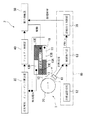
図1は本実施形態に係る超音波モータおよびその駆動回路の構成を示すブロック図である。
超音波モータ1は、圧電素子11を備えた振動体10と、この振動体10の振動によって回転される駆動体としてのロータ20とを備えて構成されている。
振動体10は、補強板12およびこの補強板12を挟んで配置された圧電素子11を積層して構成されている。補強板12は、例えば、ステンレス鋼等により略矩形平板状に形成され、振動体10全体を補強する。補強板12には、長手方向の一端側に突起部(接触部)17が一体的に形成されている。また、補強板12は、図示しない支持部を介して筐体に取り付けられている。この際、前記支持部にばね性を持たせることなどで、突起部17がロータ20の外周面に所定の付勢力で当接するように設けることが好ましい。
【0020】
圧電素子11は、所定の電圧が印加されることで圧電効果により、印加される電界の方向と一致する方向または直行する方向に変位する。各圧電素子11は、補強板12と略同一形状で形成され、補強板12の上下面にそれぞれ接着されている。
これら圧電素子11の表面は、例えば、蒸着等によりニッケルめっき層および金めっき層が形成され、電圧を印加するための電極が設けられている。また、各圧電素子11の表面は、該圧電素子11を幅方向に略三等分するように二本の溝が形成されている。さらに、これらの溝で分割された三つの領域のうち、両側の領域では長手方向を略二等分するように溝が形成されている。
このため、電極は、互いに電気的に絶縁された五つの電極13A,13B,13C,13D,13Eで構成される。そして、本実施形態では、幅方向中心の電極13Cと、この電極13Cを挟んで対角線状に配置された2つの電極13A,13Eとで超音波モータ1の駆動電極が構成されている。一方、残りの2つの電極13B,13Dで振動検出用電極が構成されている。
なお、図2の回路図に示すように、補強板12を挟んで設けられた他方の圧電素子11に設けられた電極(Co1)13Fは、前記のように区分けされておらず、駆動電極(DR1)に対応するものと振動検出用電極(Pi1)に対応するものとが共通化されて接地(GND、グランド)されている。
【0021】
このように構成された振動体10では、振動体10の圧電素子11に駆動信号を加えることで突起部17は楕円軌道を描く。すなわち、各電極13A,13C,13Eに駆動信号を印加すると、各電極に対応する圧電素子11はそれぞれ長手方向に伸縮運動(縦振動)する。この際、電極13Cの伸縮量に対して電極13A,13Eの部分の伸縮量は小さいため、振動体10には、幅方向に捻るモーメントが発生する。そして、このモーメントにより、振動体10の幅方向に揺動する屈曲運動(屈曲振動)が誘発される。このため、振動体10の突起部17は、前記縦振動および屈曲運動により楕円軌道を描いて運動する。
ここで、超音波モータ1つまり振動体10の共振周波数は、振動体10の形状等によって設定される。例えば、本実施形態では、縦振動の共振周波数は295kHz、屈曲振動の共振周波数は300kHzとされている。
【0022】
一方、振動体10の縦振動および屈曲振動に応じて電極13B,13Dに対応する圧電素子11も振動し、その振動によって発電する。従って、振動検出用電極13B,13Dからは振動に対応して信号(交流電流)が出力される。従って、これらの振動検出用電極13B,13Dにより、超音波モータ1の振動を検出する振動検出手段が構成されている。
なお、この振動は、振動体10の振動状態によって変化し、例えば、振動体10が共振状態の場合、駆動信号に対して振動検出信号はその電圧が10倍程度になるように設定することもできる。従って、振動検出信号の位相を振動体10が共振するように適宜移相して駆動電極に戻せば、振動体10を自励発振させることができる。
振動体10の突起部17が楕円軌道を描くと、突起部17が接触するロータ20に円周方向の分力が働き、ロータ20が回転する。このロータ20の回転速度は、前記振動体10の振動周波数や振動量(変位量)によって調整することができる。
【0023】
次に、超音波モータ1の駆動回路2について詳述する。駆動回路2は、大別して、波形整形・インピーダンス整合部30、フィルタ・移相部40、電力増幅部50、速度調整手段60を備えて構成されている。
速度調整手段60は、前記ロータ20の回転速度を検出するセンサ61と、ロータの目標回転速度を設定する目標値設定部62と、前記センサ61で検出された回転速度および前記目標値の差に基づく制御信号を出力するCPUからなる制御指示部63と、駆動信号制御部70とを備えている。
【0024】
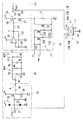
この駆動回路2の具体的な回路構成の一例を図2の回路図に示す。
なお、図2において、Vccは正電源の電位を、Vddは負電源の電位を示している。また、駆動信号制御部70のVclは制御指示部63の正電源の電位を示している。
【0025】
波形整形・インピーダンス整合部30は、図2の回路図に示すように、保護ダイオード31,32と、抵抗33,34と、電界効果トランジスタ(FET)35と、カップリングコンデンサ36とを備えて構成されている。波形整形・インピーダンス整合部30の回路入力端子(Cin)37は、超音波モータ1に設けられた振動検出用電極13B,13Dに接続されている。
超音波モータ1の振動検出用電極13B,13Dから得られた検出信号は、出力インピーダンスが非常に高い。また、駆動条件によっては電源電位Vccよりも高い電位やVddよりも低い電位が出力される場合もある。このため、検出信号は、保護ダイオード31,32を介して、FET35に入力されている。この信号は、FET35で増幅され、次段のフィルタ・移相部40に信号を伝達するのに充分な電流が得られる。
【0026】
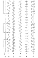
FET35で増幅された信号はカップリングコンデンサ36を介して出力され、フィルタ・移相部40に入力される。ここで、波形整形・インピーダンス整合部30の回路入力端子37に入力される検出信号の波形を図3(B)に示す。また、波形整形・インピーダンス整合部30の出力信号(カップリングコンデンサ36の出力信号であり、図2の点Aで測定される信号)の波形を図3(C)に示す。
【0027】
フィルタ・移相部40は、図2に示すように、可変抵抗41とコンデンサ42、抵抗43とコンデンサ44、抵抗45とコンデンサ46で構成される積分回路40Aと、コンデンサ47と抵抗48で構成されるハイパスフィルタ40Bとを備えて構成されている。
フィルタ・移相部40の積分回路40Aは、波形整形・インピーダンス整合部30からの入力信号を積分し、検出信号の急激な変動を吸収している。従って、積分回路40Aによって信号平均化部が構成されている。
また、ハイパスフィルタ40Bは、検出信号の不要な低周波成分を除去する。ここで、積分回路40Aはローパス特性を持つので、フィルタ・移相部40全体としてはバンドパス特性となる。
【0028】
フィルタ・移相部40の出力信号(図2の点Bで測定される信号)の波形を図3(D)に示す。フィルタ・移相部40は、図3(B)に示す検出信号の位相を、超音波モータ1の共振周波数付近で図3(D)の様に所定角度変化させる。このフィルタ・移相部40により本発明の移相手段が構成されている。
フィルタ・移相部40で変化させる位相の所定角度は、具体的には各超音波モータ1に応じて設定される。例えば、超音波モータ1における縦振動の共振周波数が295kHz、屈曲振動の共振周波数が300kHzの場合、超音波モータ1の駆動信号の周波数が、前記各周波数範囲295〜300kHzを、各周波数の差(300−295=5kHz)だけ拡大した範囲、つまり290〜305kHzの範囲内となるように制御すればよい。さらに、より好ましいのは、駆動信号の周波数が各周波数範囲295〜300kHz内となるように制御することである。超音波モータ1の振動体10は、各周波数範囲295〜300kHzの駆動信号を入力すると最も効率的に振動し、モータ1の駆動効率も向上する。また、前記範囲から僅かに、例えば各周波数の差分程度外れていても、多少効率は低下するが超音波モータ1として駆動可能である。一方、前記範囲(290〜305kHz)を外れると、振動体10の振動振幅が非常に小さくなり、超音波モータ1としての利用が困難になる。なお、最も効率的に駆動できる周波数は、振動体10の形状、固定構造などによって相違するため、超音波モータ1の設計時に適宜設定すればよい。
【0029】
電力増幅部50は、図2に示すように、演算増幅器51と、抵抗52,53,54と、FET56,57で構成されるプッシュプル回路55と、出力側抵抗58と、回路出力端子59とを備えて構成されている。
フィルタ・移相部40から出力された信号は、演算増幅器51で電圧増幅された後、プッシュプル回路55で電流増幅され、抵抗58を介して回路出力端子59から駆動信号として出力される。この駆動信号は、超音波モータ1の駆動電極13A,13C,13Eに入力される。従って、電力増幅部50によって本発明の増幅手段が構成されている。演算増幅器51の出力信号(図2の点Cで測定される信号)を図3(E)に示し、回路出力端子(Cout)59の駆動信号を図3(F)に示す。
【0030】
一方、図1に示すように、速度調整手段60のセンサ61は、ロータ20つまりは超音波モータ1の回転状態を検出して所定のパルス信号を出力するものなどが利用できる。具体的には、公知のフォトリフレクタ、フォトインタラプタ、MRセンサ等の各種の回転エンコーダ等が利用できる。
センサ61からの検出信号は、制御指示部63に送られ、ロータ20の回転速度が検出される。また、制御指示部63には、ロータ20の目標回転速度を設定する目標値設定部62からの目標値も入力される。この目標値設定部62で設定される目標値は、利用者が手動で設定してもよいし、ロータ20で駆動される機器の状態に応じて自動的に設定されるものでもよい。
【0031】
制御指示部63は、目標値設定部62から入力された目標値と、センサ61から入力された現在の回転速度とを比較し、その差を無くすための制御信号(パルス信号)を駆動信号制御部70に出力する。制御信号PWMinは、例えば、3KHzのパルス信号が利用でき、このパルス信号のデューティ比を前記目標値および実際の回転速度の差に応じて可変することで、ブレーキオフ状態(本実施形態では制御信号PWMinがHレベル信号の状態)、ブレーキオン状態(本実施形態では制御信号PWMinがHレベル信号の状態)の割合を変えて超音波モータ1の速度を制御する。従って、この制御信号PWMinはいわゆるパルス幅制御を行う信号であり、超音波モータ1は基本的にパルス幅制御によって調速されている。
【0032】
駆動信号制御部70は、図2に示すように、前記FET57および負電源Vdd間に直列に接続された振幅制限用抵抗71と、この振幅制限用抵抗71に並列に接続されたバイパス用スイッチであるFET72と、このFET72のオン、オフを制御する切替回路73とを備えている。切替回路73は、3つの抵抗731,732,733および2つのFET734,735を備えて構成されている。なお、切替回路73は、制御指示部63の電源Vclにより駆動され、かつ制御指示部63から入力される制御信号PWMinによって前記FET72をオン、オフするように構成されている。
【0033】
ここで、振幅制限用抵抗71は、抵抗58に対して適正な抵抗値、例えば50〜10万倍程度の抵抗値に設定されている。
また、フィルタ・移相部40の可変抵抗41と抵抗43の抵抗値の和(R41+R43)や、抵抗45の抵抗値(R45)は、振幅制限用抵抗71の抵抗値(R71)よりも大きくされている。
なお、フィルタ・移相部40での移相量は、約30度から240度とされている。
【0034】
このような構成の超音波モータ1の作用について説明する。
超音波モータ1の停止状態から所定のスイッチを接続するなどして駆動すると、回路出力端子59から駆動信号が超音波モータ1の駆動電極13A,13C,13Eに入力される。この入力に伴い、前記振動体10が振動し、その振動に応じた検出信号が振動検出用電極13B,13Dから回路入力端子37に入力される。この検出信号は、波形整形・インピーダンス整合部30、フィルタ・移相部40、電力増幅部50を介して超音波モータ1の駆動電極に入力される。この信号のループで電圧ゲイン1以上の条件を満たせば、この回路は正帰還となり、ループの位相差が360度の整数倍になる周波数で発振が継続し、自励発振回路となる。
【0035】
ロータ20の回転速度は、センサ61で検出されて制御指示部63に入力される。制御指示部63は、目標値設定部62で設定された目標値と前記回転速度とを比較し、その速度差に応じた制御信号PWMin を出力する。本実施形態では、図3(A)に示すように、制御指示部63から出力される制御信号PWMin は、前記振動体10にブレーキを掛けて速度を抑える場合にローレベル信号となり、ブレーキを解除する場合にハイレベル信号となるように設定されている。従って、制御指示部63は、超音波モータ1を減速する場合には、ブレーキオン制御となるローレベル信号の割合を多くし、増速する場合にはハイレベル信号の割合が多くなるように、制御信号PWMin のデューティ比を制御する。
【0036】
振動検出用電極13B,13Dから出力された検出信号は、波形整形・インピーダンス整合部30で増幅、波形整形される。この際、図3(B)に示すように制御信号PWMin がハイレベルおよびローレベル間で切り替わってノイズが発生すると、そのノイズも増幅される。
波形整形・インピーダンス整合部30で増幅、整形された信号は、フィルタ・移相部40で積分され、不要な高周波成分および低周波成分が除去される。入力信号が積分されることで、図3(D)に示すように、前記切替時のノイズも除去される。さらに、超音波モータ1の共振周波数付近で回路30,40,50および超音波モータ1で構成されるループの位相遅れが360度の整数倍となるように、信号の位相が変更される。
この信号は、電力増幅部50の演算増幅器51で増幅、整形され、図3(E)に示す略矩形波状のパルス信号とされる。このパルス信号により、プッシュプル回路55のFET56,57が交互に作動して、回路出力端子59からの駆動信号を正電位Vccおよび負電位Vdd間で切り替え、出力電流が増幅される。この駆動信号が超音波モータ1の駆動電極13A,13C,13Eに入力されることで、自励発振状態が継続する。
【0037】
一方、ロータ20の速度調整は以下の手順で行われる。
まず、制御指示部63は、センサ61で検出した回転速度および目標値設定部62の目標値の差に基づく制御信号PWMin を駆動信号制御部70に出力する。
駆動信号制御部70では、制御信号PWMin がハイレベル信号の場合、FET72が切替回路73によってオンされる。このため、FET57は負電源Vddに直結し、回路出力端子59からの駆動信号は、図3(F)に示すように、正電位Vccおよび負電位Vdd間で変動する。
一方、駆動信号制御部70では、制御信号PWMin がローレベル信号の場合、FET72が切替回路73によってオフされる。このため、FET57は振幅制限用抵抗71を介して負電源Vddに接続する。ここで、振幅制限用抵抗71の抵抗値が抵抗58に比べて非常に大きいため、回路出力端子59からの駆動信号(パルス信号)は負電位Vddまで低下することができず、正電位から僅かに降下した電圧(振幅)となる。そして、駆動信号は変位(振幅)は小さいがその電圧値は僅かに変化しているため、圧電素子11も僅かに伸縮し、振動を継続する。すなわち、抵抗58と振幅制限用抵抗71との抵抗比を適切に設定すれば、FET56がオンされた場合と、FET57がオンされた場合とで駆動信号の電圧変位を前記振動体10が停止しない限度まで小さくできる。このため、前記振動体10は発振を継続し、かつ振動変位が小さくなるためにロータ20の回転速度が低減、つまりブレーキを掛けることができる。従って、ロータ20の速度調整と発振継続とを両立することができる。
【0038】
以上に説明したように、本実施形態では、駆動信号制御部70によって駆動信号のパルス振幅が制御されているため、駆動信号制御部70により振幅制御部が構成されている。
【0039】
このような本実施形態によれば、次の効果を奏することができる。
(1)自励発振回路を利用しながらも、速度調整が行えるため、発信源や位相比較回路などが不要となり、超音波モータ1の駆動回路2の構成を簡易にできる。このため、コストを低減でき、かつ回路構成が簡易になることで、部品の故障発生の確率も低減できて信頼性も向上できる。
【0040】
(2)制御信号がローレベルとなっているブレーキオン状態でも、駆動信号は正電位Vccとその電位から僅かに低下した電位との間で変動するため、前記振動体10の発振停止状態を防止できる。このため、振動体10の発振停止に伴う駆動速度制御不能状態に陥らず、振動体10を再度発振させるための再起動操作も不要となる。このため、速度制御ができない発振の再起動状態が無くなり、超音波モータ1の制御性を格段に向上することができる。
【0041】
(3)波形整形・インピーダンス整合部30、フィルタ・移相部40、電力増幅部50を設けたので、速度制御と並行して駆動周波数を追尾することができる。このため、常に最適な周波数の駆動信号を超音波モータ1に供給することができ、モータ1の効率および駆動品質を共に向上することができる。
【0042】
(4)フィルタ・移相部40に積分回路40Aを設けたので、制御信号PWMinの切替時のノイズ等の入力信号の急激な変動を吸収でき、不安定な挙動を防止できて、駆動信号の周波数を超音波モータ1の状態に合わせて常に供給することができる。
【0043】
なお、本発明は各実施形態に限定されるものではなく、本発明の目的を達成できる範囲での変形、改良等は、本発明に含まれるものである。
例えば、波形整形・インピーダンス整合部30、フィルタ・移相部40、電力増幅部50、駆動信号制御部70等の具体的な回路構成は、前記実施形態に記載されたものに限らず、他の構成を採用してもよい。
【0044】
前記実施形態では、フィルタ・移相部40において信号平均化部を積分回路で構成していたが、他の回路で構成してもよく、要するに、検出信号の急激な変動を吸収できるものであればよい。
【0045】
また、駆動信号制御部70は、FET56と正電源Vccとの間に配置されていてもよい。さらに、駆動信号制御部70は、振幅制限用抵抗71およびFET72が並列配置されたものに限らず、電力増幅部50から出力される駆動信号の振幅を制御できるものであればよい。
【0046】
また、駆動信号制御部70は、超音波モータ1の駆動信号のパルス幅を制御するように構成してもよい。例えば、制御指示部63から出力される制御信号PWMin を利用して駆動信号のデューティ比を制御して超音波モータ1の回転速度をコントロールしてもよい。
さらに、駆動信号制御部70は、駆動信号のパルス幅および振幅の両方を制御するものでもよい。この場合には、より効率的な速度制御を行うことができる。要するに、駆動信号制御部70つまり速度調整手段60は、駆動信号のパルス幅および振幅の少なくとも一方を制御できればよく、特に、ブレーキ制御する際に、その駆動信号の振幅を僅かに変動させるなどで振動が停止しない状態に維持できるものであればよい。
但し、前記実施形態のように、振幅のみを制御するように構成すれば、駆動信号制御部70等の回路構成を簡易にできてコストを低減できる利点がある。
【0047】
さらに、電力増幅部50の構成も、プッシュプル回路を用いたものに限らず、公知の増幅回路を利用してもよい。
【0048】
超音波モータ1としても、前記実施形態に記載されたものに限らず、他の構成を採用しても良い。例えば、前記実施形態の振動体10は、ロータ20を一方向のみに回転させるように構成されていたが、例えば、駆動電極13A,13Eと、検出用電極13B,13Dとを交互に切り替えるように構成し、突起部17を正逆両方向に楕円軌道を描くように構成することで、ロータ20の回転方向を切り替えることができるように構成してもよい。
さらに、本発明の駆動回路は、前記実施形態のような薄板状の振動体10を用いた超音波モータ1の駆動回路に限らず、リング状の超音波モータや円筒状の超音波モータ、リニアモータ等の公知の各種超音波モータの駆動回路として広く利用することができる。従って、駆動体としては、ロータ20に限らず、リニア駆動されるもの等でもよく、各種超音波モータに応じて設定すればよい。また、圧電素子は、駆動体側に取り付けられていてもよく、要するに駆動体およびこの駆動体をガイドする案内部材の一方に設けられていればよい。
【0049】
フィルタ・移相部40で変化させる位相角度は、前述したように、駆動信号の周波数が、超音波モータ1のほぼ共振周波数、すなわち共振周波数またはその近傍の周波数となるように設定すればよい。なお、実際には、振動体10の形状、構造等も影響するため、共振周波数を中心に駆動信号の周波数を変更し、ピックアップ(振動検出用電極)のゲイン等で判断して最も良好な周波数を選択すればよい。
【0050】
また、本発明の駆動回路を利用した超音波モータ1の用途としては、安定かつ迅速な速度制御が可能であるため、ハードディスクやCD等のスピンドルモータや、ヘッド移動用のリニアモータ、時計のムーブメント等、小型でかつ速度制御が必要な各種アクチュエータとして利用することができる。
【0051】
【発明の効果】
以上、説明したように本発明によれば、超音波モータの駆動回路の回路構成を簡易にでき、かつ駆動速度の制御を安定して行うことができる。
【図面の簡単な説明】
【図1】本発明の実施形態の構成を示すブロック図である。
【図2】前記実施形態の駆動回路の構成を示す回路図である。
【図3】前記実施形態の駆動回路における各信号波形を示す波形図である。
【符号の説明】
1…超音波モータ、2…駆動回路、10…振動体、11…圧電素子、13A,13C,13E…駆動電極、13B,13D…振動検出用電極、20…ロータ(駆動体)、30…波形整形・インピーダンス整合部、37…回路入力端子、40…フィルタ・移相部(移相手段)、40A…積分回路(信号平均化部)、40B…ハイパスフィルタ、50…電力増幅部(増幅手段)、51…演算増幅器、55…プッシュプル回路、56,57…FET(電界効果トランジスタ)、58…出力側抵抗、59…回路出力端子、60…速度調整手段、61…センサ、62…目標値設定部、63…制御指示部、70…駆動信号制御部(パルス幅制御部、振幅制御部)、71…振幅制限用抵抗、72…FET(バイパス用スイッチ)、73…切替回路、Vcc…正電源、Vdd…負電源。[0001]
TECHNICAL FIELD OF THE INVENTION
The present invention relates to a driving circuit for an ultrasonic motor and an electronic device using the ultrasonic motor.
[0002]
[Background Art]
Conventionally, as a drive circuit of an ultrasonic motor, a drive circuit using a simple self-excited oscillation circuit (for example, see Patent Document 1) and a drive circuit using a PWM control circuit (for example, see Patent Documents 2 and 3) are known. Have been.
[0003]
[Patent Document 1]
JP-A-63-202278
[Patent Document 2]
JP-A 1-234073
[Patent Document 3]
JP-A-6-237581
[0004]
[Problems to be solved by the invention]
Since the driving circuit of
That is, when speed control is performed by the self-excited oscillation circuit, oscillation stops when the speed command value falls below a certain value. Once the oscillation stops, a pulse signal (drive signal) of several to several hundreds of waves must be input to start the oscillation, and a restart time corresponding to that is required, during which the drive becomes unstable and the speed becomes slow. Control cannot be performed.
[0005]
On the other hand, as shown in Patent Documents 2 and 3, when a PWM control circuit is used, the driving speed of the ultrasonic motor can be controlled. However, since a transmission source (VCO) and a phase comparison circuit are required, the circuit is required. Complex structure and high cost.
Further, as disclosed in Patent Document 3, when the drive speed is controlled by PWM or the like, the control of the oscillation frequency tends to be unstable, and it is generally difficult to achieve both the speed control and the oscillation frequency control.
[0006]
An object of the present invention is to provide a drive circuit and an electronic device of an ultrasonic motor that can simplify a circuit configuration and stably control a drive speed.
[0007]
[Means for Solving the Problems]
The present invention is a drive circuit for driving an ultrasonic motor having a piezoelectric element, a vibration detecting means for detecting vibration of the ultrasonic motor, and a phase shift means for changing a phase of a signal from the vibration detecting means. Amplifying means for amplifying a signal from the phase shifting means and outputting a drive signal to the ultrasonic motor, and speed adjusting means for controlling the drive signal to adjust the rotational speed of the ultrasonic motor, The phase shift means includes a signal averaging unit for averaging a signal from the vibration detection means, and performs a phase shift so that a drive signal output from the amplification means to the ultrasonic motor substantially has a resonance frequency of the ultrasonic motor. , And the speed adjusting means controls at least one of a pulse width and a pulse amplitude of the drive signal.
Here, the speed adjusting means may control only the pulse width of the drive signal, may control only the pulse amplitude, or may control both the pulse width and the pulse amplitude. Alternatively, any one of the pulse amplitudes may be controlled.
[0008]
According to this invention, the signal obtained by detecting the vibration of the ultrasonic motor by the vibration detecting means is returned to the ultrasonic motor via the phase shifting means and the amplifying means, and the phase of the signal is changed by the phase shifting means. Therefore, the drive signal from the amplifying means can be input at substantially the resonance frequency of the ultrasonic motor. Therefore, the ultrasonic motor can oscillate self-excitedly, so that a transmission source, a phase comparison circuit, and the like are not required, so that the circuit configuration can be simplified and the cost can be reduced.
In addition, since the phase shift means includes a signal averaging unit for averaging the detection signal, even if noise or a sudden change occurs in the detection signal due to speed control or the like, the influence thereof can be absorbed, and the steepness during speed control can be reduced. Unpredictable fluctuations and unstable behavior can be prevented. For this reason, the drive speed can be controlled stably.
Further, since the speed adjusting means controls at least one of the pulse width and the pulse amplitude of the drive signal, it is possible to prevent the oscillation of the ultrasonic motor from being stopped during the speed adjustment. Therefore, it is possible to avoid a state in which speed control cannot be performed due to the restart, and it is possible to perform stable and quick speed control.
[0009]
In the present invention, the phase shifting means may change the phase so that the drive signal becomes “substantially the resonance frequency of the ultrasonic motor”. “Substantially the resonance frequency of the ultrasonic motor” means that the frequency of the drive signal may be set to a frequency near the resonance frequency as well as to the resonance frequency of the ultrasonic motor. Usually, if the resonance frequency is set to the resonance frequency of the ultrasonic motor, the amplitude of the vibration increases and the efficiency of the motor can be improved.However, depending on the mounting structure of the ultrasonic motor, the resonance frequency of the ultrasonic motor is slightly shifted. This is because there are cases where it is better to provide a drive signal. That is, the drive signal may be a signal having a frequency at which a predetermined vibration amplitude can be obtained in the ultrasonic motor and can function as a motor, and the resonance frequency of the ultrasonic motor at which such characteristics are obtained and a frequency in the vicinity thereof. Is expressed as “substantially the resonance frequency of the ultrasonic motor”.
[0010]
Here, the ultrasonic motor is configured to generate a longitudinal vibration and a bending vibration, and the phase shifter is configured to increase the frequency of each of the longitudinal vibration and the bending vibration of the ultrasonic motor to a higher frequency. It is preferable to control the frequency of the drive signal within a range of an upper limit frequency obtained by adding a frequency difference and a lower limit frequency obtained by subtracting the difference of each frequency from a lower frequency.
When the ultrasonic motor has two vibration modes of longitudinal vibration and bending vibration (secondary vibration) and performs an elliptical motion, the resonance frequency is slightly different for each vibration mode. Here, among the resonance frequencies of the longitudinal vibration and the bending vibration, if the higher resonance frequency is fH, the lower resonance frequency is fL, and the difference between the resonance frequencies is Δf = fH−fL, the drive signal Is preferably in a range of fH + Δf ≧ f ≧ fL−Δf. By setting the frequency of the drive signal in such a frequency range, when there are two vibration modes, longitudinal vibration and bending vibration, the amplitude of each vibration mode can be made to be an appropriate size, and the driving efficiency of the ultrasonic motor can be improved. Can be improved.
In particular, the frequency of the drive signal is preferably equal to or higher than the low resonance frequency and equal to or lower than the high resonance frequency (fH ≧ f ≧ fL) among the resonance frequencies of the longitudinal vibration and the bending vibration. In this case, since a drive signal close to the resonance frequency of each vibration mode can be input, the drive efficiency of the ultrasonic motor can be further improved.
However, due to the influence of the fixed structure of the ultrasonic motor, the ultrasonic motor can be driven in many cases even when fH ≧ f ≧ fL. Therefore, normally, if the resonance frequency range (fH ≧ f ≧ fL) is set to a range (fH + Δf ≧ f ≧ fL−Δf) widened by a difference Δf between the resonance frequencies, the ultrasonic motor can be used. .
[0011]
Here, the ultrasonic motor includes a piezoelectric element that vibrates according to a driving signal from the amplifying unit, and a driving unit that is driven by the vibration of the piezoelectric element, and the speed adjusting unit includes a driving unit that drives the ultrasonic motor. A sensor for detecting a driving speed, a target value setting unit for setting a target driving speed of the driving body, a control instruction unit for outputting a control signal based on a difference between the driving speed detected by the sensor and the target value, and control A drive signal control unit that controls at least one of a pulse width and an amplitude of the drive signal based on a control signal from an instruction unit, wherein the drive signal control unit performs the amplification in response to a control signal from a control instruction unit. When at least one of the pulse width or the amplitude of the drive signal from the means is changed, it is preferable that the pulse width or the amplitude be limited to a value at which the oscillation of the piezoelectric element does not stop.
[0012]
According to the present invention, the control signal is output from the control instruction unit based on the drive speed and the target value detected by the sensor. Therefore, if the target value is set automatically or manually, the driving body driven by the ultrasonic motor can be automatically adjusted to the target speed. Further, since the drive signal control unit simultaneously controls the pulse width and the amplitude of the drive signal by the drive signal control unit according to the control signal, the circuit configuration can be further simplified and the cost can be reduced.
[0013]
Here, the amplification unit includes a push-pull circuit including two transistors that operate in opposite phases and an output-side resistor, and the drive signal control unit includes a positive power supply and a negative power supply that drive the push-pull circuit. The power supply and the push-pull circuit are disposed between one of the switches and the push-pull circuit, and include a bypass switch and an amplitude limiting resistor connected in parallel with each other. It is preferable that the ratio between the output-side resistor and the amplitude-limiting resistor is set so that the pulse amplitude of the drive signal output from the push-pull circuit connected via the amplitude-limiting resistor is reduced.
[0014]
According to the present invention, since the parallel circuit of the bypass switch and the amplitude limiting resistor is provided between the push-pull circuit and the power supply, the push-pull circuit is controlled only by controlling on / off of the bypass switch. The average output impedance of the circuit can be changed. For this reason, the amplitude of the drive signal can be controlled, and speed adjustment can be realized.
Therefore, the circuit configuration becomes very simple, and the cost can be reduced. In addition, since the amount of change in the amplitude of the drive signal can be controlled by the ratio between the output-side resistance of the push-pull circuit and the amplitude limiting resistance, the setting can be performed easily and finely. For this reason, the amplitude (voltage) of the drive signal can be limited to near the limit at which the oscillation of the ultrasonic motor does not stop, the speed adjustment width can be increased accordingly, and the drive speed of the ultrasonic motor can be controlled quickly. .
[0015]
Here, the driving body is a rotor that is rotated by the vibration of the piezoelectric element, the sensor detects a rotation speed of the rotor, and the control instruction unit determines the rotation speed detected by the sensor and the target speed. It is preferable to output a control signal based on the difference between the values.
The drive circuit of the present invention can be applied to any ultrasonic motor, such as a linear motor or a rotary motor. Particularly, when the rotary motor, that is, the ultrasonic motor has a rotor, the ultrasonic motor can be further reduced in size. , A wristwatch, a mobile phone, and the like.
[0016]
Here, it is preferable that the phase shift means includes an integrating circuit and a high-pass filter, and the signal averaging unit includes the integrating circuit.
If the signal averaging unit is configured by an integrating circuit, the integrating circuit has a low-pass characteristic, so that the phase shifting means can have a band-pass characteristic only by adding a separate high-pass filter. Therefore, the circuit configuration can be simplified and the cost can be reduced as compared with a case where a low-pass filter is separately provided in addition to the circuit forming the signal averaging unit.
[0017]
Here, the speed adjusting unit may include only an amplitude control unit that controls a pulse amplitude of the drive signal. If the speed adjusting means controls only the pulse amplitude, there is an advantage that the circuit configuration can be simplified and the phase control can be easily performed.
[0018]
An electronic apparatus according to another aspect of the invention includes the above-described ultrasonic motor driving circuit and an ultrasonic motor driven by the ultrasonic motor driving circuit.
According to such an electronic device, the circuit configuration can be simplified and the cost can be reduced, and the speed control of the ultrasonic motor can be stably performed. Furthermore, since the ultrasonic motor is constituted by an ultrasonic motor using a piezoelectric element, it can be easily miniaturized and can be used as various actuators such as a wristwatch, a mobile phone, a hard disk and a CD drive.
[0019]
BEST MODE FOR CARRYING OUT THE INVENTION
Hereinafter, embodiments of the present invention will be described with reference to the drawings.
FIG. 1 is a block diagram showing a configuration of an ultrasonic motor and a drive circuit thereof according to the present embodiment.
The
The vibrating
[0020]
When a predetermined voltage is applied, the
For example, a nickel plating layer and a gold plating layer are formed on the surface of the
For this reason, the electrodes are composed of five
As shown in the circuit diagram of FIG. 2, the electrode (Co1) 13F provided on the other
[0021]
In the vibrating
Here, the resonance frequency of the
[0022]
On the other hand, the
This vibration changes depending on the vibration state of the vibrating
When the
[0023]
Next, the drive circuit 2 of the
The speed adjusting means 60 includes a
[0024]
An example of a specific circuit configuration of the drive circuit 2 is shown in a circuit diagram of FIG.
In FIG. 2, Vcc indicates the potential of the positive power supply, and Vdd indicates the potential of the negative power supply. Vcl of the drive
[0025]
The waveform shaping /
The detection signals obtained from the
[0026]
The signal amplified by the
[0027]
As shown in FIG. 2, the filter /
The
The high-
[0028]
FIG. 3D shows the waveform of the output signal of the filter / phase shift unit 40 (the signal measured at point B in FIG. 2). The filter /
The predetermined angle of the phase to be changed by the filter /
[0029]
As shown in FIG. 2, the
The signal output from the filter /
[0030]
On the other hand, as shown in FIG. 1, as the
The detection signal from the
[0031]
The
[0032]
As shown in FIG. 2, the drive
[0033]
Here, the
Further, the sum (R41 + R43) of the resistance values of the variable resistance 41 and the
The amount of phase shift in the filter /
[0034]
The operation of the
When the
[0035]
The rotation speed of the
[0036]
The detection signals output from the
The signal amplified and shaped by the waveform shaping /
This signal is amplified and shaped by the
[0037]
On the other hand, the speed adjustment of the
First, the
In the drive
On the other hand, in the drive
[0038]
As described above, in the present embodiment, the pulse amplitude of the drive signal is controlled by the drive
[0039]
According to the present embodiment, the following effects can be obtained.
(1) Since the speed can be adjusted while using the self-excited oscillation circuit, a transmission source and a phase comparison circuit are not required, and the configuration of the drive circuit 2 of the
[0040]
(2) Even in the brake-on state in which the control signal is at the low level, the drive signal fluctuates between the positive potential Vcc and the potential slightly lowered from the potential, so that the oscillation stop state of the vibrating
[0041]
(3) Since the waveform shaping /
[0042]
(4) Since the
[0043]
Note that the present invention is not limited to each embodiment, and modifications, improvements, and the like within a range that can achieve the object of the present invention are included in the present invention.
For example, the specific circuit configurations of the waveform shaping /
[0044]
In the above-described embodiment, the signal averaging unit in the filter /
[0045]
Further, the drive
[0046]
Further, the drive
Further, the drive
However, if only the amplitude is controlled as in the above-described embodiment, there is an advantage that the circuit configuration of the drive
[0047]
Further, the configuration of the
[0048]
The
Further, the drive circuit of the present invention is not limited to the drive circuit of the
[0049]
As described above, the phase angle changed by the filter /
[0050]
The
[0051]
【The invention's effect】
As described above, according to the present invention, the circuit configuration of the drive circuit of the ultrasonic motor can be simplified, and the drive speed can be controlled stably.
[Brief description of the drawings]
FIG. 1 is a block diagram showing a configuration of an embodiment of the present invention.
FIG. 2 is a circuit diagram showing a configuration of a drive circuit of the embodiment.
FIG. 3 is a waveform chart showing signal waveforms in the drive circuit of the embodiment.
[Explanation of symbols]
DESCRIPTION OF
Claims (8)
前記超音波モータの振動を検出する振動検出手段と、この振動検出手段からの信号の位相を変化させる移相手段と、この移相手段からの信号を増幅して前記超音波モータに駆動信号を出力する増幅手段と、前記駆動信号を制御して超音波モータの回転速度を調整する速度調整手段とを備え、
前記移相手段は、前記振動検出手段からの信号を平均化する信号平均化部を備え、かつ前記増幅手段から超音波モータに出力される駆動信号がほぼ超音波モータの共振周波数となるように位相を変化させ、
前記速度調整手段は、前記駆動信号のパルス幅またはパルス振幅の少なくとも一方を制御することを特徴とする超音波モータ駆動回路。A drive circuit for driving an ultrasonic motor having a piezoelectric element,
Vibration detecting means for detecting the vibration of the ultrasonic motor, phase shifting means for changing the phase of the signal from the vibration detecting means, and amplifying the signal from the phase shifting means to provide a drive signal to the ultrasonic motor Amplifying means for outputting, comprising a speed adjusting means for adjusting the rotation speed of the ultrasonic motor by controlling the drive signal,
The phase shifting means includes a signal averaging unit for averaging a signal from the vibration detecting means, and a driving signal output from the amplifying means to the ultrasonic motor is substantially at a resonance frequency of the ultrasonic motor. Change the phase,
The ultrasonic motor drive circuit according to claim 1, wherein said speed adjusting means controls at least one of a pulse width and a pulse amplitude of said drive signal.
前記超音波モータは、縦振動および屈曲振動を発生するように構成され、
前記移相手段は、前記超音波モータの縦振動および屈曲振動の各共振周波数のうち、高い周波数に前記各周波数の差を加えた上限周波数および低い周波数に前記各周波数の差を引いた下限周波数の範囲内に、前記駆動信号の周波数を制御することを特徴とする超音波モータ駆動回路。The ultrasonic motor drive circuit according to claim 1,
The ultrasonic motor is configured to generate longitudinal vibration and bending vibration,
The phase shifting means includes an upper limit frequency obtained by adding a difference between the respective frequencies to a higher frequency and a lower limit frequency obtained by subtracting the difference between the respective frequencies from a lower frequency among the respective resonance frequencies of the longitudinal vibration and the bending vibration of the ultrasonic motor. An ultrasonic motor driving circuit, wherein the frequency of the driving signal is controlled within the range of (1).
前記超音波モータは、前記増幅手段からの駆動信号により振動する圧電素子と、この圧電素子の振動によって駆動する駆動体とを備えて構成され、
前記速度調整手段は、前記駆動体の駆動速度を検出するセンサと、駆動体の目標駆動速度を設定する目標値設定部と、前記センサで検出された駆動速度および前記目標値の差に基づく制御信号を出力する制御指示部と、制御指示部からの制御信号に基づいて前記駆動信号のパルス幅または振幅の少なくとも一方を制御する駆動信号制御部とを備え、
前記駆動信号制御部は、制御指示部からの制御信号に応じて前記増幅手段からの駆動信号のパルス幅またはパルス振幅の少なくとも一方を変更した際に、そのパルス幅または振幅を圧電素子の発振が停止しない大きさに制限することを特徴とする超音波モータ駆動回路。In the ultrasonic motor drive circuit according to claim 1 or 2,
The ultrasonic motor includes a piezoelectric element that vibrates according to a drive signal from the amplifying unit, and a driving body that is driven by the vibration of the piezoelectric element,
The speed adjusting means includes a sensor that detects a driving speed of the driving body, a target value setting unit that sets a target driving speed of the driving body, and control based on a difference between the driving speed detected by the sensor and the target value. A control instruction unit that outputs a signal, and a drive signal control unit that controls at least one of a pulse width and an amplitude of the drive signal based on a control signal from the control instruction unit,
The drive signal control unit, when changing at least one of the pulse width or the pulse amplitude of the drive signal from the amplifying means according to the control signal from the control instruction unit, the oscillation of the piezoelectric element changes the pulse width or the amplitude. An ultrasonic motor drive circuit, wherein the size is limited to a size that does not stop.
前記増幅手段は、逆位相で動作する2つのトランジスタと出力側抵抗で構成されたプッシュプル回路を備え、
前記駆動信号制御部は、前記プッシュプル回路を駆動する正電源および負電源の一方と、前記プッシュプル回路との間に配置され、かつ互いに並列に接続されたバイパス用スイッチおよび振幅制限用抵抗を備え、前記バイパス用スイッチを切断した際には前記電源とプッシュプル回路とが前記振幅制限用抵抗を介して接続されてプッシュプル回路から出力される駆動信号のパルス振幅が小さくなるように、前記出力側抵抗と振幅制限用抵抗との比率が設定されていることを特徴とする超音波モータ駆動回路。The ultrasonic motor drive circuit according to claim 3,
The amplification unit includes a push-pull circuit including two transistors that operate in opposite phases and an output-side resistor,
The drive signal control unit includes a bypass switch and an amplitude limiting resistor that are disposed between one of a positive power supply and a negative power supply that drives the push-pull circuit and the push-pull circuit and that are connected in parallel with each other. When the bypass switch is disconnected, the power supply and the push-pull circuit are connected via the amplitude limiting resistor so that the pulse amplitude of a drive signal output from the push-pull circuit is reduced. An ultrasonic motor drive circuit, wherein a ratio between an output side resistance and an amplitude limiting resistance is set.
前記駆動体は、前記圧電素子の振動によって回転するロータであり、
前記センサは、前記ロータの回転速度を検出し、前記制御指示部は、前記センサで検出された回転速度および前記目標値の差に基づく制御信号を出力することを特徴とする超音波モータ駆動回路。In the ultrasonic motor drive circuit according to claim 3 or 4,
The driving body is a rotor that is rotated by the vibration of the piezoelectric element,
The ultrasonic motor driving circuit, wherein the sensor detects a rotation speed of the rotor, and the control instruction unit outputs a control signal based on a difference between the rotation speed detected by the sensor and the target value. .
前記移相手段は、積分回路およびハイパスフィルタを備えて構成され、前記信号平均化部は前記積分回路で構成されていることを特徴とする超音波モータ駆動回路。The ultrasonic motor drive circuit according to any one of claims 1 to 5,
The ultrasonic motor drive circuit according to claim 1, wherein said phase shift means is provided with an integration circuit and a high-pass filter, and said signal averaging section is made up of said integration circuit.
前記速度調整手段は、前記駆動信号のパルス振幅を制御する振幅制御部のみを備えることを特徴とする超音波モータ駆動回路。The ultrasonic motor driving circuit according to any one of claims 1 to 6,
The ultrasonic motor driving circuit, wherein the speed adjusting means includes only an amplitude control unit that controls a pulse amplitude of the driving signal.
Priority Applications (1)
| Application Number | Priority Date | Filing Date | Title |
|---|---|---|---|
| JP2002325991A JP4333122B2 (en) | 2002-11-08 | 2002-11-08 | Ultrasonic motor drive circuit and electronic equipment |
Applications Claiming Priority (1)
| Application Number | Priority Date | Filing Date | Title |
|---|---|---|---|
| JP2002325991A JP4333122B2 (en) | 2002-11-08 | 2002-11-08 | Ultrasonic motor drive circuit and electronic equipment |
Related Child Applications (1)
| Application Number | Title | Priority Date | Filing Date |
|---|---|---|---|
| JP2005195235A Division JP4218665B2 (en) | 2005-07-04 | 2005-07-04 | Ultrasonic motor drive circuit and electronic equipment |
Publications (2)
| Publication Number | Publication Date |
|---|---|
| JP2004166324A true JP2004166324A (en) | 2004-06-10 |
| JP4333122B2 JP4333122B2 (en) | 2009-09-16 |
Family
ID=32805047
Family Applications (1)
| Application Number | Title | Priority Date | Filing Date |
|---|---|---|---|
| JP2002325991A Expired - Fee Related JP4333122B2 (en) | 2002-11-08 | 2002-11-08 | Ultrasonic motor drive circuit and electronic equipment |
Country Status (1)
| Country | Link |
|---|---|
| JP (1) | JP4333122B2 (en) |
Cited By (8)
| Publication number | Priority date | Publication date | Assignee | Title |
|---|---|---|---|---|
| JP2006254683A (en) * | 2005-02-10 | 2006-09-21 | Seiko Epson Corp | Piezoelectric vibrator, adjustment method of piezoelectric vibrator, piezoelectric actuator, timepiece, electronic device |
| WO2007082601A1 (en) * | 2006-01-18 | 2007-07-26 | Physik Instrumente (Pi) Gmbh & Co. Kg | Self-oscillating pwm controller for a single-phase ultrasonic motor |
| US7459830B2 (en) | 2006-02-17 | 2008-12-02 | Seiko Epson Corporation | Piezoelectric actuator, drive control method of piezoelectric actuator, and electronic device |
| JP2008306826A (en) * | 2007-06-07 | 2008-12-18 | Seiko Epson Corp | Piezoelectric actuator and driving method thereof |
| US7830103B2 (en) | 2007-07-02 | 2010-11-09 | Seiko Epson Corporation | Method for driving ultrasonic motor |
| JP2017169416A (en) * | 2016-03-18 | 2017-09-21 | セイコーエプソン株式会社 | Ultrasonic motor, robot, hand, and pump |
| JP2020162237A (en) * | 2019-03-25 | 2020-10-01 | セイコーエプソン株式会社 | Piezoelectric drive control method and piezoelectric drive |
| CN111865136A (en) * | 2019-04-26 | 2020-10-30 | 精工爱普生株式会社 | Control method of piezoelectric drive device, piezoelectric drive device, and robot |
-
2002
- 2002-11-08 JP JP2002325991A patent/JP4333122B2/en not_active Expired - Fee Related
Cited By (11)
| Publication number | Priority date | Publication date | Assignee | Title |
|---|---|---|---|---|
| JP2006254683A (en) * | 2005-02-10 | 2006-09-21 | Seiko Epson Corp | Piezoelectric vibrator, adjustment method of piezoelectric vibrator, piezoelectric actuator, timepiece, electronic device |
| US7671518B2 (en) | 2005-02-10 | 2010-03-02 | Seiko Epson Corporation | Piezoelectric vibrator, method for adjusting piezoelectric vibrator, piezoelectric actuator, timepiece, and electronic device |
| WO2007082601A1 (en) * | 2006-01-18 | 2007-07-26 | Physik Instrumente (Pi) Gmbh & Co. Kg | Self-oscillating pwm controller for a single-phase ultrasonic motor |
| US7459830B2 (en) | 2006-02-17 | 2008-12-02 | Seiko Epson Corporation | Piezoelectric actuator, drive control method of piezoelectric actuator, and electronic device |
| JP2008306826A (en) * | 2007-06-07 | 2008-12-18 | Seiko Epson Corp | Piezoelectric actuator and driving method thereof |
| US7830103B2 (en) | 2007-07-02 | 2010-11-09 | Seiko Epson Corporation | Method for driving ultrasonic motor |
| JP2017169416A (en) * | 2016-03-18 | 2017-09-21 | セイコーエプソン株式会社 | Ultrasonic motor, robot, hand, and pump |
| JP2020162237A (en) * | 2019-03-25 | 2020-10-01 | セイコーエプソン株式会社 | Piezoelectric drive control method and piezoelectric drive |
| JP7263874B2 (en) | 2019-03-25 | 2023-04-25 | セイコーエプソン株式会社 | Piezoelectric driving device control method and piezoelectric driving device |
| CN111865136A (en) * | 2019-04-26 | 2020-10-30 | 精工爱普生株式会社 | Control method of piezoelectric drive device, piezoelectric drive device, and robot |
| CN111865136B (en) * | 2019-04-26 | 2023-08-25 | 精工爱普生株式会社 | Control method of piezoelectric drive device, piezoelectric drive device and robot |
Also Published As
| Publication number | Publication date |
|---|---|
| JP4333122B2 (en) | 2009-09-16 |
Similar Documents
| Publication | Publication Date | Title |
|---|---|---|
| CN102291038B (en) | Method of controlling vibration motor and driver for vibration motor | |
| JPH10507900A (en) | Piezoelectric motor | |
| JP2007221924A (en) | Piezoelectric actuator, piezoelectric actuator drive control method, and electronic device | |
| JP4333122B2 (en) | Ultrasonic motor drive circuit and electronic equipment | |
| US5780955A (en) | Ultrasonic motor device | |
| US6573636B1 (en) | Ultrasonic motor having single booster circuit and electronic device with ultrasonic motor | |
| JP4218665B2 (en) | Ultrasonic motor drive circuit and electronic equipment | |
| JP4506704B2 (en) | Piezoelectric actuator | |
| US6400063B2 (en) | Ultrasonic motor and electronic apparatus having an ultrasonic motor | |
| JP2001137780A (en) | Piezo drive device | |
| JP2010104235A (en) | Piezoelectric actuator | |
| JP4838567B2 (en) | Frequency control circuit, motor drive device, frequency control method, motor drive device control method, and program for causing computer to execute control method | |
| JP3226894B2 (en) | Ultrasonic motor and electronic device with ultrasonic motor | |
| JPH0746866A (en) | Piezoelectric vibration control device | |
| US20010004179A1 (en) | Ultrasonic motor and electronic apparatus having an ultrasonic motor | |
| JP3722165B2 (en) | Vibration actuator driving apparatus and vibration actuator driving method | |
| JP2004336875A (en) | Driving apparatus and driving method for ultrasonic motor | |
| JP4146204B2 (en) | Ultrasonic motor drive circuit and electronic device using the same | |
| JP2552426B2 (en) | Ultrasonic motor drive circuit | |
| JP2794692B2 (en) | Ultrasonic motor drive circuit | |
| JP2008294162A (en) | Surface acoustic wave actuator | |
| JP2667811B2 (en) | Vibration type motor | |
| JP3872337B2 (en) | Ultrasonic motor | |
| JP4144229B2 (en) | Vibration wave motor | |
| JP3308711B2 (en) | Ultrasonic motor drive |
Legal Events
| Date | Code | Title | Description |
|---|---|---|---|
| A621 | Written request for application examination |
Free format text: JAPANESE INTERMEDIATE CODE: A621 Effective date: 20051101 |
|
| RD02 | Notification of acceptance of power of attorney |
Free format text: JAPANESE INTERMEDIATE CODE: A7422 Effective date: 20070704 |
|
| RD02 | Notification of acceptance of power of attorney |
Free format text: JAPANESE INTERMEDIATE CODE: A7422 Effective date: 20070813 |
|
| A131 | Notification of reasons for refusal |
Free format text: JAPANESE INTERMEDIATE CODE: A131 Effective date: 20080930 |
|
| A521 | Written amendment |
Free format text: JAPANESE INTERMEDIATE CODE: A523 Effective date: 20081201 |
|
| TRDD | Decision of grant or rejection written | ||
| A01 | Written decision to grant a patent or to grant a registration (utility model) |
Free format text: JAPANESE INTERMEDIATE CODE: A01 Effective date: 20090602 |
|
| A01 | Written decision to grant a patent or to grant a registration (utility model) |
Free format text: JAPANESE INTERMEDIATE CODE: A01 |
|
| A61 | First payment of annual fees (during grant procedure) |
Free format text: JAPANESE INTERMEDIATE CODE: A61 Effective date: 20090615 |
|
| FPAY | Renewal fee payment (event date is renewal date of database) |
Free format text: PAYMENT UNTIL: 20120703 Year of fee payment: 3 |
|
| R150 | Certificate of patent or registration of utility model |
Free format text: JAPANESE INTERMEDIATE CODE: R150 |
|
| FPAY | Renewal fee payment (event date is renewal date of database) |
Free format text: PAYMENT UNTIL: 20120703 Year of fee payment: 3 |
|
| FPAY | Renewal fee payment (event date is renewal date of database) |
Free format text: PAYMENT UNTIL: 20130703 Year of fee payment: 4 |
|
| S531 | Written request for registration of change of domicile |
Free format text: JAPANESE INTERMEDIATE CODE: R313531 |
|
| R350 | Written notification of registration of transfer |
Free format text: JAPANESE INTERMEDIATE CODE: R350 |
|
| LAPS | Cancellation because of no payment of annual fees |