KR20150047473A - Method and device for reinforcing and/or lining material - Google Patents
Method and device for reinforcing and/or lining material Download PDFInfo
- Publication number
- KR20150047473A KR20150047473A KR1020157000722A KR20157000722A KR20150047473A KR 20150047473 A KR20150047473 A KR 20150047473A KR 1020157000722 A KR1020157000722 A KR 1020157000722A KR 20157000722 A KR20157000722 A KR 20157000722A KR 20150047473 A KR20150047473 A KR 20150047473A
- Authority
- KR
- South Korea
- Prior art keywords
- lining
- tool
- reinforcing
- reinforcement
- porous material
- Prior art date
Links
- 239000000463 material Substances 0.000 title claims abstract description 254
- 230000003014 reinforcing effect Effects 0.000 title claims abstract description 221
- 238000000034 method Methods 0.000 title claims abstract description 115
- 239000011148 porous material Substances 0.000 claims abstract description 182
- 230000002787 reinforcement Effects 0.000 claims description 256
- 238000003825 pressing Methods 0.000 claims description 43
- 230000008878 coupling Effects 0.000 claims description 41
- 238000010168 coupling process Methods 0.000 claims description 41
- 238000005859 coupling reaction Methods 0.000 claims description 41
- 239000012815 thermoplastic material Substances 0.000 claims description 34
- 230000001681 protective effect Effects 0.000 claims description 27
- 229920001169 thermoplastic Polymers 0.000 claims description 26
- 239000004416 thermosoftening plastic Substances 0.000 claims description 25
- 238000005520 cutting process Methods 0.000 claims description 17
- 238000005304 joining Methods 0.000 claims description 3
- 230000007246 mechanism Effects 0.000 claims description 3
- 230000008569 process Effects 0.000 description 40
- 230000005855 radiation Effects 0.000 description 24
- 230000013011 mating Effects 0.000 description 17
- 230000011218 segmentation Effects 0.000 description 17
- 229920000642 polymer Polymers 0.000 description 13
- 230000035515 penetration Effects 0.000 description 12
- 230000008901 benefit Effects 0.000 description 11
- 239000002131 composite material Substances 0.000 description 11
- 238000013459 approach Methods 0.000 description 9
- 235000021251 pulses Nutrition 0.000 description 9
- 239000000919 ceramic Substances 0.000 description 8
- 239000004020 conductor Substances 0.000 description 8
- 230000000694 effects Effects 0.000 description 8
- -1 polypropylene Polymers 0.000 description 8
- 230000002829 reductive effect Effects 0.000 description 8
- 230000006870 function Effects 0.000 description 7
- 230000010355 oscillation Effects 0.000 description 7
- 230000002093 peripheral effect Effects 0.000 description 7
- 239000002023 wood Substances 0.000 description 7
- 238000010521 absorption reaction Methods 0.000 description 6
- 238000010276 construction Methods 0.000 description 6
- 238000005553 drilling Methods 0.000 description 6
- 239000000945 filler Substances 0.000 description 6
- 239000006260 foam Substances 0.000 description 6
- 229910052751 metal Inorganic materials 0.000 description 6
- 239000002184 metal Substances 0.000 description 6
- 229920001643 poly(ether ketone) Polymers 0.000 description 6
- 230000004323 axial length Effects 0.000 description 5
- 238000009826 distribution Methods 0.000 description 5
- 239000011521 glass Substances 0.000 description 5
- 238000003780 insertion Methods 0.000 description 5
- 230000037431 insertion Effects 0.000 description 5
- 230000004048 modification Effects 0.000 description 5
- 238000012986 modification Methods 0.000 description 5
- 230000007704 transition Effects 0.000 description 5
- VTYYLEPIZMXCLO-UHFFFAOYSA-L Calcium carbonate Chemical compound [Ca+2].[O-]C([O-])=O VTYYLEPIZMXCLO-UHFFFAOYSA-L 0.000 description 4
- 230000005670 electromagnetic radiation Effects 0.000 description 4
- 239000000835 fiber Substances 0.000 description 4
- 238000010438 heat treatment Methods 0.000 description 4
- 230000000149 penetrating effect Effects 0.000 description 4
- 239000000049 pigment Substances 0.000 description 4
- 229920001343 polytetrafluoroethylene Polymers 0.000 description 4
- 239000004810 polytetrafluoroethylene Substances 0.000 description 4
- 230000003313 weakening effect Effects 0.000 description 4
- 238000003466 welding Methods 0.000 description 4
- 230000005611 electricity Effects 0.000 description 3
- 239000007788 liquid Substances 0.000 description 3
- 238000004519 manufacturing process Methods 0.000 description 3
- 239000000203 mixture Substances 0.000 description 3
- 239000002245 particle Substances 0.000 description 3
- 229920003023 plastic Polymers 0.000 description 3
- 239000004033 plastic Substances 0.000 description 3
- 238000012545 processing Methods 0.000 description 3
- 230000009467 reduction Effects 0.000 description 3
- 239000007787 solid Substances 0.000 description 3
- OKTJSMMVPCPJKN-UHFFFAOYSA-N Carbon Chemical compound [C] OKTJSMMVPCPJKN-UHFFFAOYSA-N 0.000 description 2
- 239000004698 Polyethylene Substances 0.000 description 2
- 239000004743 Polypropylene Substances 0.000 description 2
- 229910052581 Si3N4 Inorganic materials 0.000 description 2
- 229910000831 Steel Inorganic materials 0.000 description 2
- 229910001069 Ti alloy Inorganic materials 0.000 description 2
- 238000005299 abrasion Methods 0.000 description 2
- 230000002745 absorbent Effects 0.000 description 2
- 239000002250 absorbent Substances 0.000 description 2
- 230000000712 assembly Effects 0.000 description 2
- 238000000429 assembly Methods 0.000 description 2
- 238000005452 bending Methods 0.000 description 2
- 229910000019 calcium carbonate Inorganic materials 0.000 description 2
- 229910052799 carbon Inorganic materials 0.000 description 2
- 238000001816 cooling Methods 0.000 description 2
- 238000012937 correction Methods 0.000 description 2
- 238000013016 damping Methods 0.000 description 2
- 238000006073 displacement reaction Methods 0.000 description 2
- 230000009969 flowable effect Effects 0.000 description 2
- 239000000446 fuel Substances 0.000 description 2
- 239000003365 glass fiber Substances 0.000 description 2
- 230000000977 initiatory effect Effects 0.000 description 2
- 238000002844 melting Methods 0.000 description 2
- 230000008018 melting Effects 0.000 description 2
- 239000006262 metallic foam Substances 0.000 description 2
- 229920003229 poly(methyl methacrylate) Polymers 0.000 description 2
- 229920000573 polyethylene Polymers 0.000 description 2
- 239000004926 polymethyl methacrylate Substances 0.000 description 2
- 229920001155 polypropylene Polymers 0.000 description 2
- 239000000843 powder Substances 0.000 description 2
- 230000000717 retained effect Effects 0.000 description 2
- 238000010079 rubber tapping Methods 0.000 description 2
- 238000007790 scraping Methods 0.000 description 2
- 238000007493 shaping process Methods 0.000 description 2
- HBMJWWWQQXIZIP-UHFFFAOYSA-N silicon carbide Chemical compound [Si+]#[C-] HBMJWWWQQXIZIP-UHFFFAOYSA-N 0.000 description 2
- 229910010271 silicon carbide Inorganic materials 0.000 description 2
- HQVNEWCFYHHQES-UHFFFAOYSA-N silicon nitride Chemical compound N12[Si]34N5[Si]62N3[Si]51N64 HQVNEWCFYHHQES-UHFFFAOYSA-N 0.000 description 2
- 239000010959 steel Substances 0.000 description 2
- 229920000638 styrene acrylonitrile Polymers 0.000 description 2
- 238000012546 transfer Methods 0.000 description 2
- 241000269627 Amphiuma means Species 0.000 description 1
- 101100258233 Caenorhabditis elegans sun-1 gene Proteins 0.000 description 1
- OYPRJOBELJOOCE-UHFFFAOYSA-N Calcium Chemical compound [Ca] OYPRJOBELJOOCE-UHFFFAOYSA-N 0.000 description 1
- 229920000049 Carbon (fiber) Polymers 0.000 description 1
- WQZGKKKJIJFFOK-GASJEMHNSA-N Glucose Natural products OC[C@H]1OC(O)[C@H](O)[C@@H](O)[C@@H]1O WQZGKKKJIJFFOK-GASJEMHNSA-N 0.000 description 1
- 229920000271 Kevlar® Polymers 0.000 description 1
- 229920000106 Liquid crystal polymer Polymers 0.000 description 1
- 229920000571 Nylon 11 Polymers 0.000 description 1
- 229920000299 Nylon 12 Polymers 0.000 description 1
- 229920002292 Nylon 6 Polymers 0.000 description 1
- 229920002302 Nylon 6,6 Polymers 0.000 description 1
- 229930040373 Paraformaldehyde Natural products 0.000 description 1
- 235000010627 Phaseolus vulgaris Nutrition 0.000 description 1
- 244000046052 Phaseolus vulgaris Species 0.000 description 1
- 239000004952 Polyamide Substances 0.000 description 1
- 239000004697 Polyetherimide Substances 0.000 description 1
- 239000004642 Polyimide Substances 0.000 description 1
- 239000004793 Polystyrene Substances 0.000 description 1
- VYPSYNLAJGMNEJ-UHFFFAOYSA-N Silicium dioxide Chemical compound O=[Si]=O VYPSYNLAJGMNEJ-UHFFFAOYSA-N 0.000 description 1
- GWEVSGVZZGPLCZ-UHFFFAOYSA-N Titan oxide Chemical compound O=[Ti]=O GWEVSGVZZGPLCZ-UHFFFAOYSA-N 0.000 description 1
- RTAQQCXQSZGOHL-UHFFFAOYSA-N Titanium Chemical compound [Ti] RTAQQCXQSZGOHL-UHFFFAOYSA-N 0.000 description 1
- NIXOWILDQLNWCW-UHFFFAOYSA-N acrylic acid group Chemical group C(C=C)(=O)O NIXOWILDQLNWCW-UHFFFAOYSA-N 0.000 description 1
- 239000004676 acrylonitrile butadiene styrene Substances 0.000 description 1
- 229920003232 aliphatic polyester Polymers 0.000 description 1
- 229910045601 alloy Inorganic materials 0.000 description 1
- 239000000956 alloy Substances 0.000 description 1
- 229910052782 aluminium Inorganic materials 0.000 description 1
- XAGFODPZIPBFFR-UHFFFAOYSA-N aluminium Chemical compound [Al] XAGFODPZIPBFFR-UHFFFAOYSA-N 0.000 description 1
- 210000003484 anatomy Anatomy 0.000 description 1
- 230000003466 anti-cipated effect Effects 0.000 description 1
- 239000011324 bead Substances 0.000 description 1
- WQZGKKKJIJFFOK-VFUOTHLCSA-N beta-D-glucose Chemical compound OC[C@H]1O[C@@H](O)[C@H](O)[C@@H](O)[C@@H]1O WQZGKKKJIJFFOK-VFUOTHLCSA-N 0.000 description 1
- 230000000903 blocking effect Effects 0.000 description 1
- 239000011449 brick Substances 0.000 description 1
- 229910052791 calcium Inorganic materials 0.000 description 1
- 239000011575 calcium Substances 0.000 description 1
- 239000004917 carbon fiber Substances 0.000 description 1
- 150000004649 carbonic acid derivatives Chemical class 0.000 description 1
- 239000011111 cardboard Substances 0.000 description 1
- 238000005266 casting Methods 0.000 description 1
- 239000003054 catalyst Substances 0.000 description 1
- 229910010293 ceramic material Inorganic materials 0.000 description 1
- 230000008859 change Effects 0.000 description 1
- 239000011093 chipboard Substances 0.000 description 1
- 239000011248 coating agent Substances 0.000 description 1
- 238000000576 coating method Methods 0.000 description 1
- 150000001875 compounds Chemical class 0.000 description 1
- 239000004567 concrete Substances 0.000 description 1
- 229920001577 copolymer Polymers 0.000 description 1
- 238000005034 decoration Methods 0.000 description 1
- 230000001419 dependent effect Effects 0.000 description 1
- 238000013461 design Methods 0.000 description 1
- 238000010586 diagram Methods 0.000 description 1
- KZHJGOXRZJKJNY-UHFFFAOYSA-N dioxosilane;oxo(oxoalumanyloxy)alumane Chemical compound O=[Si]=O.O=[Si]=O.O=[Al]O[Al]=O.O=[Al]O[Al]=O.O=[Al]O[Al]=O KZHJGOXRZJKJNY-UHFFFAOYSA-N 0.000 description 1
- 239000012777 electrically insulating material Substances 0.000 description 1
- 230000005284 excitation Effects 0.000 description 1
- 238000002474 experimental method Methods 0.000 description 1
- 239000002657 fibrous material Substances 0.000 description 1
- 238000007710 freezing Methods 0.000 description 1
- 230000008014 freezing Effects 0.000 description 1
- 229910021485 fumed silica Inorganic materials 0.000 description 1
- 239000008103 glucose Substances 0.000 description 1
- 150000004676 glycans Chemical class 0.000 description 1
- 239000010439 graphite Substances 0.000 description 1
- 229910002804 graphite Inorganic materials 0.000 description 1
- 239000012943 hotmelt Substances 0.000 description 1
- 230000006872 improvement Effects 0.000 description 1
- 238000007373 indentation Methods 0.000 description 1
- 238000001764 infiltration Methods 0.000 description 1
- 230000008595 infiltration Effects 0.000 description 1
- 238000002955 isolation Methods 0.000 description 1
- 239000004761 kevlar Substances 0.000 description 1
- 238000012886 linear function Methods 0.000 description 1
- 230000007774 longterm Effects 0.000 description 1
- 238000007734 materials engineering Methods 0.000 description 1
- 239000011159 matrix material Substances 0.000 description 1
- 238000005259 measurement Methods 0.000 description 1
- 238000011089 mechanical engineering Methods 0.000 description 1
- 230000010358 mechanical oscillation Effects 0.000 description 1
- 238000010309 melting process Methods 0.000 description 1
- 229910001092 metal group alloy Inorganic materials 0.000 description 1
- 239000005300 metallic glass Substances 0.000 description 1
- 150000002739 metals Chemical class 0.000 description 1
- 239000010445 mica Substances 0.000 description 1
- 229910052618 mica group Inorganic materials 0.000 description 1
- 238000003801 milling Methods 0.000 description 1
- 238000000465 moulding Methods 0.000 description 1
- 229910052863 mullite Inorganic materials 0.000 description 1
- 239000002105 nanoparticle Substances 0.000 description 1
- 239000002071 nanotube Substances 0.000 description 1
- 229910052759 nickel Inorganic materials 0.000 description 1
- ORQBXQOJMQIAOY-UHFFFAOYSA-N nobelium Chemical compound [No] ORQBXQOJMQIAOY-UHFFFAOYSA-N 0.000 description 1
- TWNQGVIAIRXVLR-UHFFFAOYSA-N oxo(oxoalumanyloxy)alumane Chemical compound O=[Al]O[Al]=O TWNQGVIAIRXVLR-UHFFFAOYSA-N 0.000 description 1
- RVTZCBVAJQQJTK-UHFFFAOYSA-N oxygen(2-);zirconium(4+) Chemical compound [O-2].[O-2].[Zr+4] RVTZCBVAJQQJTK-UHFFFAOYSA-N 0.000 description 1
- 230000036961 partial effect Effects 0.000 description 1
- 230000008447 perception Effects 0.000 description 1
- 230000000737 periodic effect Effects 0.000 description 1
- 239000011505 plaster Substances 0.000 description 1
- 229920002647 polyamide Polymers 0.000 description 1
- 239000004417 polycarbonate Substances 0.000 description 1
- 229920000515 polycarbonate Polymers 0.000 description 1
- 229920001692 polycarbonate urethane Polymers 0.000 description 1
- 229920000728 polyester Polymers 0.000 description 1
- 229920001601 polyetherimide Polymers 0.000 description 1
- 229920001721 polyimide Polymers 0.000 description 1
- 229920006324 polyoxymethylene Polymers 0.000 description 1
- 239000005017 polysaccharide Substances 0.000 description 1
- 229920001282 polysaccharide Polymers 0.000 description 1
- 229920002223 polystyrene Polymers 0.000 description 1
- 239000004800 polyvinyl chloride Substances 0.000 description 1
- 229920000915 polyvinyl chloride Polymers 0.000 description 1
- SCUZVMOVTVSBLE-UHFFFAOYSA-N prop-2-enenitrile;styrene Chemical compound C=CC#N.C=CC1=CC=CC=C1 SCUZVMOVTVSBLE-UHFFFAOYSA-N 0.000 description 1
- 238000004080 punching Methods 0.000 description 1
- 238000010791 quenching Methods 0.000 description 1
- 230000000171 quenching effect Effects 0.000 description 1
- 239000012783 reinforcing fiber Substances 0.000 description 1
- 239000012779 reinforcing material Substances 0.000 description 1
- 150000004671 saturated fatty acids Chemical class 0.000 description 1
- 235000003441 saturated fatty acids Nutrition 0.000 description 1
- 238000007789 sealing Methods 0.000 description 1
- 239000001488 sodium phosphate Substances 0.000 description 1
- 229910000162 sodium phosphate Inorganic materials 0.000 description 1
- 239000007779 soft material Substances 0.000 description 1
- 239000010935 stainless steel Substances 0.000 description 1
- 229910001220 stainless steel Inorganic materials 0.000 description 1
- 239000003351 stiffener Substances 0.000 description 1
- 239000004575 stone Substances 0.000 description 1
- 239000000758 substrate Substances 0.000 description 1
- 230000000153 supplemental effect Effects 0.000 description 1
- 230000003746 surface roughness Effects 0.000 description 1
- 239000002470 thermal conductor Substances 0.000 description 1
- 229910052719 titanium Inorganic materials 0.000 description 1
- 239000010936 titanium Substances 0.000 description 1
- OGIDPMRJRNCKJF-UHFFFAOYSA-N titanium oxide Inorganic materials [Ti]=O OGIDPMRJRNCKJF-UHFFFAOYSA-N 0.000 description 1
- 238000002627 tracheal intubation Methods 0.000 description 1
- RYFMWSXOAZQYPI-UHFFFAOYSA-K trisodium phosphate Chemical compound [Na+].[Na+].[Na+].[O-]P([O-])([O-])=O RYFMWSXOAZQYPI-UHFFFAOYSA-K 0.000 description 1
- 229920000785 ultra high molecular weight polyethylene Polymers 0.000 description 1
- 239000011800 void material Substances 0.000 description 1
- 229910001928 zirconium oxide Inorganic materials 0.000 description 1
Images


Classifications
-
- B—PERFORMING OPERATIONS; TRANSPORTING
- B29—WORKING OF PLASTICS; WORKING OF SUBSTANCES IN A PLASTIC STATE IN GENERAL
- B29C—SHAPING OR JOINING OF PLASTICS; SHAPING OF MATERIAL IN A PLASTIC STATE, NOT OTHERWISE PROVIDED FOR; AFTER-TREATMENT OF THE SHAPED PRODUCTS, e.g. REPAIRING
- B29C65/00—Joining or sealing of preformed parts, e.g. welding of plastics materials; Apparatus therefor
- B29C65/02—Joining or sealing of preformed parts, e.g. welding of plastics materials; Apparatus therefor by heating, with or without pressure
- B29C65/08—Joining or sealing of preformed parts, e.g. welding of plastics materials; Apparatus therefor by heating, with or without pressure using ultrasonic vibrations
-
- B—PERFORMING OPERATIONS; TRANSPORTING
- B29—WORKING OF PLASTICS; WORKING OF SUBSTANCES IN A PLASTIC STATE IN GENERAL
- B29C—SHAPING OR JOINING OF PLASTICS; SHAPING OF MATERIAL IN A PLASTIC STATE, NOT OTHERWISE PROVIDED FOR; AFTER-TREATMENT OF THE SHAPED PRODUCTS, e.g. REPAIRING
- B29C63/00—Lining or sheathing, i.e. applying preformed layers or sheathings of plastics; Apparatus therefor
- B29C63/0065—Heat treatment
- B29C63/0069—Heat treatment of tubular articles
-
- B—PERFORMING OPERATIONS; TRANSPORTING
- B29—WORKING OF PLASTICS; WORKING OF SUBSTANCES IN A PLASTIC STATE IN GENERAL
- B29C—SHAPING OR JOINING OF PLASTICS; SHAPING OF MATERIAL IN A PLASTIC STATE, NOT OTHERWISE PROVIDED FOR; AFTER-TREATMENT OF THE SHAPED PRODUCTS, e.g. REPAIRING
- B29C63/00—Lining or sheathing, i.e. applying preformed layers or sheathings of plastics; Apparatus therefor
- B29C63/26—Lining or sheathing of internal surfaces
- B29C63/34—Lining or sheathing of internal surfaces using tubular layers or sheathings
- B29C63/341—Lining or sheathing of internal surfaces using tubular layers or sheathings pressed against the wall by mechanical means
-
- B—PERFORMING OPERATIONS; TRANSPORTING
- B29—WORKING OF PLASTICS; WORKING OF SUBSTANCES IN A PLASTIC STATE IN GENERAL
- B29C—SHAPING OR JOINING OF PLASTICS; SHAPING OF MATERIAL IN A PLASTIC STATE, NOT OTHERWISE PROVIDED FOR; AFTER-TREATMENT OF THE SHAPED PRODUCTS, e.g. REPAIRING
- B29C65/00—Joining or sealing of preformed parts, e.g. welding of plastics materials; Apparatus therefor
- B29C65/02—Joining or sealing of preformed parts, e.g. welding of plastics materials; Apparatus therefor by heating, with or without pressure
- B29C65/14—Joining or sealing of preformed parts, e.g. welding of plastics materials; Apparatus therefor by heating, with or without pressure using wave energy, i.e. electromagnetic radiation, or particle radiation
- B29C65/1403—Joining or sealing of preformed parts, e.g. welding of plastics materials; Apparatus therefor by heating, with or without pressure using wave energy, i.e. electromagnetic radiation, or particle radiation characterised by the type of electromagnetic or particle radiation
- B29C65/1412—Infrared [IR] radiation
-
- B—PERFORMING OPERATIONS; TRANSPORTING
- B29—WORKING OF PLASTICS; WORKING OF SUBSTANCES IN A PLASTIC STATE IN GENERAL
- B29C—SHAPING OR JOINING OF PLASTICS; SHAPING OF MATERIAL IN A PLASTIC STATE, NOT OTHERWISE PROVIDED FOR; AFTER-TREATMENT OF THE SHAPED PRODUCTS, e.g. REPAIRING
- B29C65/00—Joining or sealing of preformed parts, e.g. welding of plastics materials; Apparatus therefor
- B29C65/02—Joining or sealing of preformed parts, e.g. welding of plastics materials; Apparatus therefor by heating, with or without pressure
- B29C65/18—Joining or sealing of preformed parts, e.g. welding of plastics materials; Apparatus therefor by heating, with or without pressure using heated tools
-
- B—PERFORMING OPERATIONS; TRANSPORTING
- B29—WORKING OF PLASTICS; WORKING OF SUBSTANCES IN A PLASTIC STATE IN GENERAL
- B29C—SHAPING OR JOINING OF PLASTICS; SHAPING OF MATERIAL IN A PLASTIC STATE, NOT OTHERWISE PROVIDED FOR; AFTER-TREATMENT OF THE SHAPED PRODUCTS, e.g. REPAIRING
- B29C65/00—Joining or sealing of preformed parts, e.g. welding of plastics materials; Apparatus therefor
- B29C65/02—Joining or sealing of preformed parts, e.g. welding of plastics materials; Apparatus therefor by heating, with or without pressure
- B29C65/34—Joining or sealing of preformed parts, e.g. welding of plastics materials; Apparatus therefor by heating, with or without pressure using heated elements which remain in the joint, e.g. "verlorenes Schweisselement"
- B29C65/3404—Joining or sealing of preformed parts, e.g. welding of plastics materials; Apparatus therefor by heating, with or without pressure using heated elements which remain in the joint, e.g. "verlorenes Schweisselement" characterised by the type of heated elements which remain in the joint
-
- B—PERFORMING OPERATIONS; TRANSPORTING
- B29—WORKING OF PLASTICS; WORKING OF SUBSTANCES IN A PLASTIC STATE IN GENERAL
- B29C—SHAPING OR JOINING OF PLASTICS; SHAPING OF MATERIAL IN A PLASTIC STATE, NOT OTHERWISE PROVIDED FOR; AFTER-TREATMENT OF THE SHAPED PRODUCTS, e.g. REPAIRING
- B29C65/00—Joining or sealing of preformed parts, e.g. welding of plastics materials; Apparatus therefor
- B29C65/74—Joining or sealing of preformed parts, e.g. welding of plastics materials; Apparatus therefor by welding and severing, or by joining and severing, the severing being performed in the area to be joined, next to the area to be joined, in the joint area or next to the joint area
- B29C65/743—Joining or sealing of preformed parts, e.g. welding of plastics materials; Apparatus therefor by welding and severing, or by joining and severing, the severing being performed in the area to be joined, next to the area to be joined, in the joint area or next to the joint area using the same tool for both joining and severing, said tool being monobloc or formed by several parts mounted together and forming a monobloc
- B29C65/7437—Joining or sealing of preformed parts, e.g. welding of plastics materials; Apparatus therefor by welding and severing, or by joining and severing, the severing being performed in the area to be joined, next to the area to be joined, in the joint area or next to the joint area using the same tool for both joining and severing, said tool being monobloc or formed by several parts mounted together and forming a monobloc the tool being a perforating tool
-
- B—PERFORMING OPERATIONS; TRANSPORTING
- B29—WORKING OF PLASTICS; WORKING OF SUBSTANCES IN A PLASTIC STATE IN GENERAL
- B29C—SHAPING OR JOINING OF PLASTICS; SHAPING OF MATERIAL IN A PLASTIC STATE, NOT OTHERWISE PROVIDED FOR; AFTER-TREATMENT OF THE SHAPED PRODUCTS, e.g. REPAIRING
- B29C65/00—Joining or sealing of preformed parts, e.g. welding of plastics materials; Apparatus therefor
- B29C65/74—Joining or sealing of preformed parts, e.g. welding of plastics materials; Apparatus therefor by welding and severing, or by joining and severing, the severing being performed in the area to be joined, next to the area to be joined, in the joint area or next to the joint area
- B29C65/743—Joining or sealing of preformed parts, e.g. welding of plastics materials; Apparatus therefor by welding and severing, or by joining and severing, the severing being performed in the area to be joined, next to the area to be joined, in the joint area or next to the joint area using the same tool for both joining and severing, said tool being monobloc or formed by several parts mounted together and forming a monobloc
- B29C65/7443—Joining or sealing of preformed parts, e.g. welding of plastics materials; Apparatus therefor by welding and severing, or by joining and severing, the severing being performed in the area to be joined, next to the area to be joined, in the joint area or next to the joint area using the same tool for both joining and severing, said tool being monobloc or formed by several parts mounted together and forming a monobloc by means of ultrasonic vibrations
-
- B—PERFORMING OPERATIONS; TRANSPORTING
- B29—WORKING OF PLASTICS; WORKING OF SUBSTANCES IN A PLASTIC STATE IN GENERAL
- B29C—SHAPING OR JOINING OF PLASTICS; SHAPING OF MATERIAL IN A PLASTIC STATE, NOT OTHERWISE PROVIDED FOR; AFTER-TREATMENT OF THE SHAPED PRODUCTS, e.g. REPAIRING
- B29C66/00—General aspects of processes or apparatus for joining preformed parts
- B29C66/01—General aspects dealing with the joint area or with the area to be joined
- B29C66/02—Preparation of the material, in the area to be joined, prior to joining or welding
- B29C66/022—Mechanical pre-treatments, e.g. reshaping
- B29C66/0224—Mechanical pre-treatments, e.g. reshaping with removal of material
- B29C66/02241—Cutting, e.g. by using waterjets, or sawing
- B29C66/02242—Perforating or boring
-
- B—PERFORMING OPERATIONS; TRANSPORTING
- B29—WORKING OF PLASTICS; WORKING OF SUBSTANCES IN A PLASTIC STATE IN GENERAL
- B29C—SHAPING OR JOINING OF PLASTICS; SHAPING OF MATERIAL IN A PLASTIC STATE, NOT OTHERWISE PROVIDED FOR; AFTER-TREATMENT OF THE SHAPED PRODUCTS, e.g. REPAIRING
- B29C66/00—General aspects of processes or apparatus for joining preformed parts
- B29C66/01—General aspects dealing with the joint area or with the area to be joined
- B29C66/05—Particular design of joint configurations
- B29C66/10—Particular design of joint configurations particular design of the joint cross-sections
- B29C66/11—Joint cross-sections comprising a single joint-segment, i.e. one of the parts to be joined comprising a single joint-segment in the joint cross-section
- B29C66/112—Single lapped joints
- B29C66/1122—Single lap to lap joints, i.e. overlap joints
-
- B—PERFORMING OPERATIONS; TRANSPORTING
- B29—WORKING OF PLASTICS; WORKING OF SUBSTANCES IN A PLASTIC STATE IN GENERAL
- B29C—SHAPING OR JOINING OF PLASTICS; SHAPING OF MATERIAL IN A PLASTIC STATE, NOT OTHERWISE PROVIDED FOR; AFTER-TREATMENT OF THE SHAPED PRODUCTS, e.g. REPAIRING
- B29C66/00—General aspects of processes or apparatus for joining preformed parts
- B29C66/01—General aspects dealing with the joint area or with the area to be joined
- B29C66/05—Particular design of joint configurations
- B29C66/20—Particular design of joint configurations particular design of the joint lines, e.g. of the weld lines
- B29C66/21—Particular design of joint configurations particular design of the joint lines, e.g. of the weld lines said joint lines being formed by a single dot or dash or by several dots or dashes, i.e. spot joining or spot welding
-
- B—PERFORMING OPERATIONS; TRANSPORTING
- B29—WORKING OF PLASTICS; WORKING OF SUBSTANCES IN A PLASTIC STATE IN GENERAL
- B29C—SHAPING OR JOINING OF PLASTICS; SHAPING OF MATERIAL IN A PLASTIC STATE, NOT OTHERWISE PROVIDED FOR; AFTER-TREATMENT OF THE SHAPED PRODUCTS, e.g. REPAIRING
- B29C66/00—General aspects of processes or apparatus for joining preformed parts
- B29C66/01—General aspects dealing with the joint area or with the area to be joined
- B29C66/05—Particular design of joint configurations
- B29C66/302—Particular design of joint configurations the area to be joined comprising melt initiators
- B29C66/3022—Particular design of joint configurations the area to be joined comprising melt initiators said melt initiators being integral with at least one of the parts to be joined
-
- B—PERFORMING OPERATIONS; TRANSPORTING
- B29—WORKING OF PLASTICS; WORKING OF SUBSTANCES IN A PLASTIC STATE IN GENERAL
- B29C—SHAPING OR JOINING OF PLASTICS; SHAPING OF MATERIAL IN A PLASTIC STATE, NOT OTHERWISE PROVIDED FOR; AFTER-TREATMENT OF THE SHAPED PRODUCTS, e.g. REPAIRING
- B29C66/00—General aspects of processes or apparatus for joining preformed parts
- B29C66/01—General aspects dealing with the joint area or with the area to be joined
- B29C66/05—Particular design of joint configurations
- B29C66/303—Particular design of joint configurations the joint involving an anchoring effect
- B29C66/3032—Particular design of joint configurations the joint involving an anchoring effect making use of protusions or cavities belonging to at least one of the parts to be joined
- B29C66/30325—Particular design of joint configurations the joint involving an anchoring effect making use of protusions or cavities belonging to at least one of the parts to be joined making use of cavities belonging to at least one of the parts to be joined
- B29C66/30326—Particular design of joint configurations the joint involving an anchoring effect making use of protusions or cavities belonging to at least one of the parts to be joined making use of cavities belonging to at least one of the parts to be joined in the form of porosity
-
- B—PERFORMING OPERATIONS; TRANSPORTING
- B29—WORKING OF PLASTICS; WORKING OF SUBSTANCES IN A PLASTIC STATE IN GENERAL
- B29C—SHAPING OR JOINING OF PLASTICS; SHAPING OF MATERIAL IN A PLASTIC STATE, NOT OTHERWISE PROVIDED FOR; AFTER-TREATMENT OF THE SHAPED PRODUCTS, e.g. REPAIRING
- B29C66/00—General aspects of processes or apparatus for joining preformed parts
- B29C66/01—General aspects dealing with the joint area or with the area to be joined
- B29C66/05—Particular design of joint configurations
- B29C66/304—Joining through openings in an intermediate part of the article
-
- B—PERFORMING OPERATIONS; TRANSPORTING
- B29—WORKING OF PLASTICS; WORKING OF SUBSTANCES IN A PLASTIC STATE IN GENERAL
- B29C—SHAPING OR JOINING OF PLASTICS; SHAPING OF MATERIAL IN A PLASTIC STATE, NOT OTHERWISE PROVIDED FOR; AFTER-TREATMENT OF THE SHAPED PRODUCTS, e.g. REPAIRING
- B29C66/00—General aspects of processes or apparatus for joining preformed parts
- B29C66/01—General aspects dealing with the joint area or with the area to be joined
- B29C66/348—Avoiding melting or weakening of the zone directly next to the joint area, e.g. by cooling
-
- B—PERFORMING OPERATIONS; TRANSPORTING
- B29—WORKING OF PLASTICS; WORKING OF SUBSTANCES IN A PLASTIC STATE IN GENERAL
- B29C—SHAPING OR JOINING OF PLASTICS; SHAPING OF MATERIAL IN A PLASTIC STATE, NOT OTHERWISE PROVIDED FOR; AFTER-TREATMENT OF THE SHAPED PRODUCTS, e.g. REPAIRING
- B29C66/00—General aspects of processes or apparatus for joining preformed parts
- B29C66/40—General aspects of joining substantially flat articles, e.g. plates, sheets or web-like materials; Making flat seams in tubular or hollow articles; Joining single elements to substantially flat surfaces
- B29C66/47—Joining single elements to sheets, plates or other substantially flat surfaces
- B29C66/474—Joining single elements to sheets, plates or other substantially flat surfaces said single elements being substantially non-flat
-
- B—PERFORMING OPERATIONS; TRANSPORTING
- B29—WORKING OF PLASTICS; WORKING OF SUBSTANCES IN A PLASTIC STATE IN GENERAL
- B29C—SHAPING OR JOINING OF PLASTICS; SHAPING OF MATERIAL IN A PLASTIC STATE, NOT OTHERWISE PROVIDED FOR; AFTER-TREATMENT OF THE SHAPED PRODUCTS, e.g. REPAIRING
- B29C66/00—General aspects of processes or apparatus for joining preformed parts
- B29C66/70—General aspects of processes or apparatus for joining preformed parts characterised by the composition, physical properties or the structure of the material of the parts to be joined; Joining with non-plastics material
- B29C66/72—General aspects of processes or apparatus for joining preformed parts characterised by the composition, physical properties or the structure of the material of the parts to be joined; Joining with non-plastics material characterised by the structure of the material of the parts to be joined
- B29C66/721—Fibre-reinforced materials
-
- B—PERFORMING OPERATIONS; TRANSPORTING
- B29—WORKING OF PLASTICS; WORKING OF SUBSTANCES IN A PLASTIC STATE IN GENERAL
- B29C—SHAPING OR JOINING OF PLASTICS; SHAPING OF MATERIAL IN A PLASTIC STATE, NOT OTHERWISE PROVIDED FOR; AFTER-TREATMENT OF THE SHAPED PRODUCTS, e.g. REPAIRING
- B29C66/00—General aspects of processes or apparatus for joining preformed parts
- B29C66/70—General aspects of processes or apparatus for joining preformed parts characterised by the composition, physical properties or the structure of the material of the parts to be joined; Joining with non-plastics material
- B29C66/72—General aspects of processes or apparatus for joining preformed parts characterised by the composition, physical properties or the structure of the material of the parts to be joined; Joining with non-plastics material characterised by the structure of the material of the parts to be joined
- B29C66/723—General aspects of processes or apparatus for joining preformed parts characterised by the composition, physical properties or the structure of the material of the parts to be joined; Joining with non-plastics material characterised by the structure of the material of the parts to be joined being multi-layered
-
- B—PERFORMING OPERATIONS; TRANSPORTING
- B29—WORKING OF PLASTICS; WORKING OF SUBSTANCES IN A PLASTIC STATE IN GENERAL
- B29C—SHAPING OR JOINING OF PLASTICS; SHAPING OF MATERIAL IN A PLASTIC STATE, NOT OTHERWISE PROVIDED FOR; AFTER-TREATMENT OF THE SHAPED PRODUCTS, e.g. REPAIRING
- B29C66/00—General aspects of processes or apparatus for joining preformed parts
- B29C66/70—General aspects of processes or apparatus for joining preformed parts characterised by the composition, physical properties or the structure of the material of the parts to be joined; Joining with non-plastics material
- B29C66/72—General aspects of processes or apparatus for joining preformed parts characterised by the composition, physical properties or the structure of the material of the parts to be joined; Joining with non-plastics material characterised by the structure of the material of the parts to be joined
- B29C66/727—General aspects of processes or apparatus for joining preformed parts characterised by the composition, physical properties or the structure of the material of the parts to be joined; Joining with non-plastics material characterised by the structure of the material of the parts to be joined being porous, e.g. foam
-
- B—PERFORMING OPERATIONS; TRANSPORTING
- B29—WORKING OF PLASTICS; WORKING OF SUBSTANCES IN A PLASTIC STATE IN GENERAL
- B29C—SHAPING OR JOINING OF PLASTICS; SHAPING OF MATERIAL IN A PLASTIC STATE, NOT OTHERWISE PROVIDED FOR; AFTER-TREATMENT OF THE SHAPED PRODUCTS, e.g. REPAIRING
- B29C66/00—General aspects of processes or apparatus for joining preformed parts
- B29C66/70—General aspects of processes or apparatus for joining preformed parts characterised by the composition, physical properties or the structure of the material of the parts to be joined; Joining with non-plastics material
- B29C66/73—General aspects of processes or apparatus for joining preformed parts characterised by the composition, physical properties or the structure of the material of the parts to be joined; Joining with non-plastics material characterised by the intensive physical properties of the material of the parts to be joined, by the optical properties of the material of the parts to be joined, by the extensive physical properties of the parts to be joined, by the state of the material of the parts to be joined or by the material of the parts to be joined being a thermoplastic or a thermoset
- B29C66/739—General aspects of processes or apparatus for joining preformed parts characterised by the composition, physical properties or the structure of the material of the parts to be joined; Joining with non-plastics material characterised by the intensive physical properties of the material of the parts to be joined, by the optical properties of the material of the parts to be joined, by the extensive physical properties of the parts to be joined, by the state of the material of the parts to be joined or by the material of the parts to be joined being a thermoplastic or a thermoset characterised by the material of the parts to be joined being a thermoplastic or a thermoset
- B29C66/7392—General aspects of processes or apparatus for joining preformed parts characterised by the composition, physical properties or the structure of the material of the parts to be joined; Joining with non-plastics material characterised by the intensive physical properties of the material of the parts to be joined, by the optical properties of the material of the parts to be joined, by the extensive physical properties of the parts to be joined, by the state of the material of the parts to be joined or by the material of the parts to be joined being a thermoplastic or a thermoset characterised by the material of the parts to be joined being a thermoplastic or a thermoset characterised by the material of at least one of the parts being a thermoplastic
-
- B—PERFORMING OPERATIONS; TRANSPORTING
- B29—WORKING OF PLASTICS; WORKING OF SUBSTANCES IN A PLASTIC STATE IN GENERAL
- B29C—SHAPING OR JOINING OF PLASTICS; SHAPING OF MATERIAL IN A PLASTIC STATE, NOT OTHERWISE PROVIDED FOR; AFTER-TREATMENT OF THE SHAPED PRODUCTS, e.g. REPAIRING
- B29C66/00—General aspects of processes or apparatus for joining preformed parts
- B29C66/70—General aspects of processes or apparatus for joining preformed parts characterised by the composition, physical properties or the structure of the material of the parts to be joined; Joining with non-plastics material
- B29C66/74—Joining plastics material to non-plastics material
- B29C66/746—Joining plastics material to non-plastics material to inorganic materials not provided for in groups B29C66/742 - B29C66/744
- B29C66/7463—Concrete
-
- B—PERFORMING OPERATIONS; TRANSPORTING
- B29—WORKING OF PLASTICS; WORKING OF SUBSTANCES IN A PLASTIC STATE IN GENERAL
- B29C—SHAPING OR JOINING OF PLASTICS; SHAPING OF MATERIAL IN A PLASTIC STATE, NOT OTHERWISE PROVIDED FOR; AFTER-TREATMENT OF THE SHAPED PRODUCTS, e.g. REPAIRING
- B29C66/00—General aspects of processes or apparatus for joining preformed parts
- B29C66/70—General aspects of processes or apparatus for joining preformed parts characterised by the composition, physical properties or the structure of the material of the parts to be joined; Joining with non-plastics material
- B29C66/74—Joining plastics material to non-plastics material
- B29C66/748—Joining plastics material to non-plastics material to natural products or their composites, not provided for in groups B29C66/742 - B29C66/746
- B29C66/7486—Paper, e.g. cardboard
-
- B—PERFORMING OPERATIONS; TRANSPORTING
- B29—WORKING OF PLASTICS; WORKING OF SUBSTANCES IN A PLASTIC STATE IN GENERAL
- B29C—SHAPING OR JOINING OF PLASTICS; SHAPING OF MATERIAL IN A PLASTIC STATE, NOT OTHERWISE PROVIDED FOR; AFTER-TREATMENT OF THE SHAPED PRODUCTS, e.g. REPAIRING
- B29C66/00—General aspects of processes or apparatus for joining preformed parts
- B29C66/80—General aspects of machine operations or constructions and parts thereof
- B29C66/83—General aspects of machine operations or constructions and parts thereof characterised by the movement of the joining or pressing tools
- B29C66/832—Reciprocating joining or pressing tools
- B29C66/8322—Joining or pressing tools reciprocating along one axis
-
- E—FIXED CONSTRUCTIONS
- E04—BUILDING
- E04B—GENERAL BUILDING CONSTRUCTIONS; WALLS, e.g. PARTITIONS; ROOFS; FLOORS; CEILINGS; INSULATION OR OTHER PROTECTION OF BUILDINGS
- E04B1/00—Constructions in general; Structures which are not restricted either to walls, e.g. partitions, or floors or ceilings or roofs
- E04B1/62—Insulation or other protection; Elements or use of specified material therefor
- E04B1/92—Protection against other undesired influences or dangers
-
- F—MECHANICAL ENGINEERING; LIGHTING; HEATING; WEAPONS; BLASTING
- F16—ENGINEERING ELEMENTS AND UNITS; GENERAL MEASURES FOR PRODUCING AND MAINTAINING EFFECTIVE FUNCTIONING OF MACHINES OR INSTALLATIONS; THERMAL INSULATION IN GENERAL
- F16B—DEVICES FOR FASTENING OR SECURING CONSTRUCTIONAL ELEMENTS OR MACHINE PARTS TOGETHER, e.g. NAILS, BOLTS, CIRCLIPS, CLAMPS, CLIPS OR WEDGES; JOINTS OR JOINTING
- F16B5/00—Joining sheets or plates, e.g. panels, to one another or to strips or bars parallel to them
- F16B5/01—Joining sheets or plates, e.g. panels, to one another or to strips or bars parallel to them by means of fastening elements specially adapted for honeycomb panels
-
- B—PERFORMING OPERATIONS; TRANSPORTING
- B29—WORKING OF PLASTICS; WORKING OF SUBSTANCES IN A PLASTIC STATE IN GENERAL
- B29C—SHAPING OR JOINING OF PLASTICS; SHAPING OF MATERIAL IN A PLASTIC STATE, NOT OTHERWISE PROVIDED FOR; AFTER-TREATMENT OF THE SHAPED PRODUCTS, e.g. REPAIRING
- B29C65/00—Joining or sealing of preformed parts, e.g. welding of plastics materials; Apparatus therefor
- B29C65/02—Joining or sealing of preformed parts, e.g. welding of plastics materials; Apparatus therefor by heating, with or without pressure
- B29C65/06—Joining or sealing of preformed parts, e.g. welding of plastics materials; Apparatus therefor by heating, with or without pressure using friction, e.g. spin welding
- B29C65/0681—Joining or sealing of preformed parts, e.g. welding of plastics materials; Apparatus therefor by heating, with or without pressure using friction, e.g. spin welding created by a tool
-
- B—PERFORMING OPERATIONS; TRANSPORTING
- B29—WORKING OF PLASTICS; WORKING OF SUBSTANCES IN A PLASTIC STATE IN GENERAL
- B29C—SHAPING OR JOINING OF PLASTICS; SHAPING OF MATERIAL IN A PLASTIC STATE, NOT OTHERWISE PROVIDED FOR; AFTER-TREATMENT OF THE SHAPED PRODUCTS, e.g. REPAIRING
- B29C65/00—Joining or sealing of preformed parts, e.g. welding of plastics materials; Apparatus therefor
- B29C65/02—Joining or sealing of preformed parts, e.g. welding of plastics materials; Apparatus therefor by heating, with or without pressure
- B29C65/08—Joining or sealing of preformed parts, e.g. welding of plastics materials; Apparatus therefor by heating, with or without pressure using ultrasonic vibrations
- B29C65/081—Joining or sealing of preformed parts, e.g. welding of plastics materials; Apparatus therefor by heating, with or without pressure using ultrasonic vibrations having a component of vibration not perpendicular to the welding surface
-
- B—PERFORMING OPERATIONS; TRANSPORTING
- B29—WORKING OF PLASTICS; WORKING OF SUBSTANCES IN A PLASTIC STATE IN GENERAL
- B29C—SHAPING OR JOINING OF PLASTICS; SHAPING OF MATERIAL IN A PLASTIC STATE, NOT OTHERWISE PROVIDED FOR; AFTER-TREATMENT OF THE SHAPED PRODUCTS, e.g. REPAIRING
- B29C65/00—Joining or sealing of preformed parts, e.g. welding of plastics materials; Apparatus therefor
- B29C65/02—Joining or sealing of preformed parts, e.g. welding of plastics materials; Apparatus therefor by heating, with or without pressure
- B29C65/14—Joining or sealing of preformed parts, e.g. welding of plastics materials; Apparatus therefor by heating, with or without pressure using wave energy, i.e. electromagnetic radiation, or particle radiation
- B29C65/1403—Joining or sealing of preformed parts, e.g. welding of plastics materials; Apparatus therefor by heating, with or without pressure using wave energy, i.e. electromagnetic radiation, or particle radiation characterised by the type of electromagnetic or particle radiation
- B29C65/1409—Visible light radiation
-
- B—PERFORMING OPERATIONS; TRANSPORTING
- B29—WORKING OF PLASTICS; WORKING OF SUBSTANCES IN A PLASTIC STATE IN GENERAL
- B29C—SHAPING OR JOINING OF PLASTICS; SHAPING OF MATERIAL IN A PLASTIC STATE, NOT OTHERWISE PROVIDED FOR; AFTER-TREATMENT OF THE SHAPED PRODUCTS, e.g. REPAIRING
- B29C65/00—Joining or sealing of preformed parts, e.g. welding of plastics materials; Apparatus therefor
- B29C65/02—Joining or sealing of preformed parts, e.g. welding of plastics materials; Apparatus therefor by heating, with or without pressure
- B29C65/14—Joining or sealing of preformed parts, e.g. welding of plastics materials; Apparatus therefor by heating, with or without pressure using wave energy, i.e. electromagnetic radiation, or particle radiation
- B29C65/1487—Joining or sealing of preformed parts, e.g. welding of plastics materials; Apparatus therefor by heating, with or without pressure using wave energy, i.e. electromagnetic radiation, or particle radiation making use of light guides
-
- B—PERFORMING OPERATIONS; TRANSPORTING
- B29—WORKING OF PLASTICS; WORKING OF SUBSTANCES IN A PLASTIC STATE IN GENERAL
- B29C—SHAPING OR JOINING OF PLASTICS; SHAPING OF MATERIAL IN A PLASTIC STATE, NOT OTHERWISE PROVIDED FOR; AFTER-TREATMENT OF THE SHAPED PRODUCTS, e.g. REPAIRING
- B29C65/00—Joining or sealing of preformed parts, e.g. welding of plastics materials; Apparatus therefor
- B29C65/02—Joining or sealing of preformed parts, e.g. welding of plastics materials; Apparatus therefor by heating, with or without pressure
- B29C65/14—Joining or sealing of preformed parts, e.g. welding of plastics materials; Apparatus therefor by heating, with or without pressure using wave energy, i.e. electromagnetic radiation, or particle radiation
- B29C65/16—Laser beams
- B29C65/1603—Laser beams characterised by the type of electromagnetic radiation
- B29C65/1609—Visible light radiation, e.g. by visible light lasers
-
- B—PERFORMING OPERATIONS; TRANSPORTING
- B29—WORKING OF PLASTICS; WORKING OF SUBSTANCES IN A PLASTIC STATE IN GENERAL
- B29C—SHAPING OR JOINING OF PLASTICS; SHAPING OF MATERIAL IN A PLASTIC STATE, NOT OTHERWISE PROVIDED FOR; AFTER-TREATMENT OF THE SHAPED PRODUCTS, e.g. REPAIRING
- B29C65/00—Joining or sealing of preformed parts, e.g. welding of plastics materials; Apparatus therefor
- B29C65/02—Joining or sealing of preformed parts, e.g. welding of plastics materials; Apparatus therefor by heating, with or without pressure
- B29C65/14—Joining or sealing of preformed parts, e.g. welding of plastics materials; Apparatus therefor by heating, with or without pressure using wave energy, i.e. electromagnetic radiation, or particle radiation
- B29C65/16—Laser beams
- B29C65/1603—Laser beams characterised by the type of electromagnetic radiation
- B29C65/1612—Infrared [IR] radiation, e.g. by infrared lasers
-
- B—PERFORMING OPERATIONS; TRANSPORTING
- B29—WORKING OF PLASTICS; WORKING OF SUBSTANCES IN A PLASTIC STATE IN GENERAL
- B29C—SHAPING OR JOINING OF PLASTICS; SHAPING OF MATERIAL IN A PLASTIC STATE, NOT OTHERWISE PROVIDED FOR; AFTER-TREATMENT OF THE SHAPED PRODUCTS, e.g. REPAIRING
- B29C65/00—Joining or sealing of preformed parts, e.g. welding of plastics materials; Apparatus therefor
- B29C65/02—Joining or sealing of preformed parts, e.g. welding of plastics materials; Apparatus therefor by heating, with or without pressure
- B29C65/14—Joining or sealing of preformed parts, e.g. welding of plastics materials; Apparatus therefor by heating, with or without pressure using wave energy, i.e. electromagnetic radiation, or particle radiation
- B29C65/16—Laser beams
- B29C65/1629—Laser beams characterised by the way of heating the interface
- B29C65/1674—Laser beams characterised by the way of heating the interface making use of laser diodes
-
- B—PERFORMING OPERATIONS; TRANSPORTING
- B29—WORKING OF PLASTICS; WORKING OF SUBSTANCES IN A PLASTIC STATE IN GENERAL
- B29C—SHAPING OR JOINING OF PLASTICS; SHAPING OF MATERIAL IN A PLASTIC STATE, NOT OTHERWISE PROVIDED FOR; AFTER-TREATMENT OF THE SHAPED PRODUCTS, e.g. REPAIRING
- B29C65/00—Joining or sealing of preformed parts, e.g. welding of plastics materials; Apparatus therefor
- B29C65/02—Joining or sealing of preformed parts, e.g. welding of plastics materials; Apparatus therefor by heating, with or without pressure
- B29C65/14—Joining or sealing of preformed parts, e.g. welding of plastics materials; Apparatus therefor by heating, with or without pressure using wave energy, i.e. electromagnetic radiation, or particle radiation
- B29C65/16—Laser beams
- B29C65/1687—Laser beams making use of light guides
-
- B—PERFORMING OPERATIONS; TRANSPORTING
- B29—WORKING OF PLASTICS; WORKING OF SUBSTANCES IN A PLASTIC STATE IN GENERAL
- B29C—SHAPING OR JOINING OF PLASTICS; SHAPING OF MATERIAL IN A PLASTIC STATE, NOT OTHERWISE PROVIDED FOR; AFTER-TREATMENT OF THE SHAPED PRODUCTS, e.g. REPAIRING
- B29C65/00—Joining or sealing of preformed parts, e.g. welding of plastics materials; Apparatus therefor
- B29C65/02—Joining or sealing of preformed parts, e.g. welding of plastics materials; Apparatus therefor by heating, with or without pressure
- B29C65/34—Joining or sealing of preformed parts, e.g. welding of plastics materials; Apparatus therefor by heating, with or without pressure using heated elements which remain in the joint, e.g. "verlorenes Schweisselement"
- B29C65/3404—Joining or sealing of preformed parts, e.g. welding of plastics materials; Apparatus therefor by heating, with or without pressure using heated elements which remain in the joint, e.g. "verlorenes Schweisselement" characterised by the type of heated elements which remain in the joint
- B29C65/3408—Joining or sealing of preformed parts, e.g. welding of plastics materials; Apparatus therefor by heating, with or without pressure using heated elements which remain in the joint, e.g. "verlorenes Schweisselement" characterised by the type of heated elements which remain in the joint comprising single particles, e.g. fillers or discontinuous fibre-reinforcements
- B29C65/3412—Joining or sealing of preformed parts, e.g. welding of plastics materials; Apparatus therefor by heating, with or without pressure using heated elements which remain in the joint, e.g. "verlorenes Schweisselement" characterised by the type of heated elements which remain in the joint comprising single particles, e.g. fillers or discontinuous fibre-reinforcements comprising fillers
-
- B—PERFORMING OPERATIONS; TRANSPORTING
- B29—WORKING OF PLASTICS; WORKING OF SUBSTANCES IN A PLASTIC STATE IN GENERAL
- B29C—SHAPING OR JOINING OF PLASTICS; SHAPING OF MATERIAL IN A PLASTIC STATE, NOT OTHERWISE PROVIDED FOR; AFTER-TREATMENT OF THE SHAPED PRODUCTS, e.g. REPAIRING
- B29C65/00—Joining or sealing of preformed parts, e.g. welding of plastics materials; Apparatus therefor
- B29C65/02—Joining or sealing of preformed parts, e.g. welding of plastics materials; Apparatus therefor by heating, with or without pressure
- B29C65/34—Joining or sealing of preformed parts, e.g. welding of plastics materials; Apparatus therefor by heating, with or without pressure using heated elements which remain in the joint, e.g. "verlorenes Schweisselement"
- B29C65/3472—Joining or sealing of preformed parts, e.g. welding of plastics materials; Apparatus therefor by heating, with or without pressure using heated elements which remain in the joint, e.g. "verlorenes Schweisselement" characterised by the composition of the heated elements which remain in the joint
- B29C65/3476—Joining or sealing of preformed parts, e.g. welding of plastics materials; Apparatus therefor by heating, with or without pressure using heated elements which remain in the joint, e.g. "verlorenes Schweisselement" characterised by the composition of the heated elements which remain in the joint being metallic
-
- B—PERFORMING OPERATIONS; TRANSPORTING
- B29—WORKING OF PLASTICS; WORKING OF SUBSTANCES IN A PLASTIC STATE IN GENERAL
- B29C—SHAPING OR JOINING OF PLASTICS; SHAPING OF MATERIAL IN A PLASTIC STATE, NOT OTHERWISE PROVIDED FOR; AFTER-TREATMENT OF THE SHAPED PRODUCTS, e.g. REPAIRING
- B29C66/00—General aspects of processes or apparatus for joining preformed parts
- B29C66/01—General aspects dealing with the joint area or with the area to be joined
- B29C66/03—After-treatments in the joint area
- B29C66/032—Mechanical after-treatments
-
- B—PERFORMING OPERATIONS; TRANSPORTING
- B29—WORKING OF PLASTICS; WORKING OF SUBSTANCES IN A PLASTIC STATE IN GENERAL
- B29C—SHAPING OR JOINING OF PLASTICS; SHAPING OF MATERIAL IN A PLASTIC STATE, NOT OTHERWISE PROVIDED FOR; AFTER-TREATMENT OF THE SHAPED PRODUCTS, e.g. REPAIRING
- B29C66/00—General aspects of processes or apparatus for joining preformed parts
- B29C66/70—General aspects of processes or apparatus for joining preformed parts characterised by the composition, physical properties or the structure of the material of the parts to be joined; Joining with non-plastics material
- B29C66/71—General aspects of processes or apparatus for joining preformed parts characterised by the composition, physical properties or the structure of the material of the parts to be joined; Joining with non-plastics material characterised by the composition of the plastics material of the parts to be joined
-
- B—PERFORMING OPERATIONS; TRANSPORTING
- B29—WORKING OF PLASTICS; WORKING OF SUBSTANCES IN A PLASTIC STATE IN GENERAL
- B29C—SHAPING OR JOINING OF PLASTICS; SHAPING OF MATERIAL IN A PLASTIC STATE, NOT OTHERWISE PROVIDED FOR; AFTER-TREATMENT OF THE SHAPED PRODUCTS, e.g. REPAIRING
- B29C66/00—General aspects of processes or apparatus for joining preformed parts
- B29C66/70—General aspects of processes or apparatus for joining preformed parts characterised by the composition, physical properties or the structure of the material of the parts to be joined; Joining with non-plastics material
- B29C66/72—General aspects of processes or apparatus for joining preformed parts characterised by the composition, physical properties or the structure of the material of the parts to be joined; Joining with non-plastics material characterised by the structure of the material of the parts to be joined
- B29C66/721—Fibre-reinforced materials
- B29C66/7212—Fibre-reinforced materials characterised by the composition of the fibres
-
- B—PERFORMING OPERATIONS; TRANSPORTING
- B29—WORKING OF PLASTICS; WORKING OF SUBSTANCES IN A PLASTIC STATE IN GENERAL
- B29C—SHAPING OR JOINING OF PLASTICS; SHAPING OF MATERIAL IN A PLASTIC STATE, NOT OTHERWISE PROVIDED FOR; AFTER-TREATMENT OF THE SHAPED PRODUCTS, e.g. REPAIRING
- B29C66/00—General aspects of processes or apparatus for joining preformed parts
- B29C66/70—General aspects of processes or apparatus for joining preformed parts characterised by the composition, physical properties or the structure of the material of the parts to be joined; Joining with non-plastics material
- B29C66/72—General aspects of processes or apparatus for joining preformed parts characterised by the composition, physical properties or the structure of the material of the parts to be joined; Joining with non-plastics material characterised by the structure of the material of the parts to be joined
- B29C66/721—Fibre-reinforced materials
- B29C66/7214—Fibre-reinforced materials characterised by the length of the fibres
- B29C66/72141—Fibres of continuous length
-
- B—PERFORMING OPERATIONS; TRANSPORTING
- B29—WORKING OF PLASTICS; WORKING OF SUBSTANCES IN A PLASTIC STATE IN GENERAL
- B29C—SHAPING OR JOINING OF PLASTICS; SHAPING OF MATERIAL IN A PLASTIC STATE, NOT OTHERWISE PROVIDED FOR; AFTER-TREATMENT OF THE SHAPED PRODUCTS, e.g. REPAIRING
- B29C66/00—General aspects of processes or apparatus for joining preformed parts
- B29C66/70—General aspects of processes or apparatus for joining preformed parts characterised by the composition, physical properties or the structure of the material of the parts to be joined; Joining with non-plastics material
- B29C66/72—General aspects of processes or apparatus for joining preformed parts characterised by the composition, physical properties or the structure of the material of the parts to be joined; Joining with non-plastics material characterised by the structure of the material of the parts to be joined
- B29C66/721—Fibre-reinforced materials
- B29C66/7214—Fibre-reinforced materials characterised by the length of the fibres
- B29C66/72143—Fibres of discontinuous lengths
-
- B—PERFORMING OPERATIONS; TRANSPORTING
- B29—WORKING OF PLASTICS; WORKING OF SUBSTANCES IN A PLASTIC STATE IN GENERAL
- B29C—SHAPING OR JOINING OF PLASTICS; SHAPING OF MATERIAL IN A PLASTIC STATE, NOT OTHERWISE PROVIDED FOR; AFTER-TREATMENT OF THE SHAPED PRODUCTS, e.g. REPAIRING
- B29C66/00—General aspects of processes or apparatus for joining preformed parts
- B29C66/70—General aspects of processes or apparatus for joining preformed parts characterised by the composition, physical properties or the structure of the material of the parts to be joined; Joining with non-plastics material
- B29C66/73—General aspects of processes or apparatus for joining preformed parts characterised by the composition, physical properties or the structure of the material of the parts to be joined; Joining with non-plastics material characterised by the intensive physical properties of the material of the parts to be joined, by the optical properties of the material of the parts to be joined, by the extensive physical properties of the parts to be joined, by the state of the material of the parts to be joined or by the material of the parts to be joined being a thermoplastic or a thermoset
- B29C66/731—General aspects of processes or apparatus for joining preformed parts characterised by the composition, physical properties or the structure of the material of the parts to be joined; Joining with non-plastics material characterised by the intensive physical properties of the material of the parts to be joined, by the optical properties of the material of the parts to be joined, by the extensive physical properties of the parts to be joined, by the state of the material of the parts to be joined or by the material of the parts to be joined being a thermoplastic or a thermoset characterised by the intensive physical properties of the material of the parts to be joined
- B29C66/7316—Surface properties
- B29C66/73161—Roughness or rugosity
-
- B—PERFORMING OPERATIONS; TRANSPORTING
- B29—WORKING OF PLASTICS; WORKING OF SUBSTANCES IN A PLASTIC STATE IN GENERAL
- B29C—SHAPING OR JOINING OF PLASTICS; SHAPING OF MATERIAL IN A PLASTIC STATE, NOT OTHERWISE PROVIDED FOR; AFTER-TREATMENT OF THE SHAPED PRODUCTS, e.g. REPAIRING
- B29C66/00—General aspects of processes or apparatus for joining preformed parts
- B29C66/70—General aspects of processes or apparatus for joining preformed parts characterised by the composition, physical properties or the structure of the material of the parts to be joined; Joining with non-plastics material
- B29C66/74—Joining plastics material to non-plastics material
- B29C66/746—Joining plastics material to non-plastics material to inorganic materials not provided for in groups B29C66/742 - B29C66/744
- B29C66/7461—Ceramics
-
- B—PERFORMING OPERATIONS; TRANSPORTING
- B29—WORKING OF PLASTICS; WORKING OF SUBSTANCES IN A PLASTIC STATE IN GENERAL
- B29C—SHAPING OR JOINING OF PLASTICS; SHAPING OF MATERIAL IN A PLASTIC STATE, NOT OTHERWISE PROVIDED FOR; AFTER-TREATMENT OF THE SHAPED PRODUCTS, e.g. REPAIRING
- B29C66/00—General aspects of processes or apparatus for joining preformed parts
- B29C66/70—General aspects of processes or apparatus for joining preformed parts characterised by the composition, physical properties or the structure of the material of the parts to be joined; Joining with non-plastics material
- B29C66/74—Joining plastics material to non-plastics material
- B29C66/748—Joining plastics material to non-plastics material to natural products or their composites, not provided for in groups B29C66/742 - B29C66/746
- B29C66/7487—Wood
-
- B—PERFORMING OPERATIONS; TRANSPORTING
- B29—WORKING OF PLASTICS; WORKING OF SUBSTANCES IN A PLASTIC STATE IN GENERAL
- B29C—SHAPING OR JOINING OF PLASTICS; SHAPING OF MATERIAL IN A PLASTIC STATE, NOT OTHERWISE PROVIDED FOR; AFTER-TREATMENT OF THE SHAPED PRODUCTS, e.g. REPAIRING
- B29C66/00—General aspects of processes or apparatus for joining preformed parts
- B29C66/90—Measuring or controlling the joining process
- B29C66/95—Measuring or controlling the joining process by measuring or controlling specific variables not covered by groups B29C66/91 - B29C66/94
- B29C66/951—Measuring or controlling the joining process by measuring or controlling specific variables not covered by groups B29C66/91 - B29C66/94 by measuring or controlling the vibration frequency and/or the vibration amplitude of vibrating joining tools, e.g. of ultrasonic welding tools
- B29C66/9512—Measuring or controlling the joining process by measuring or controlling specific variables not covered by groups B29C66/91 - B29C66/94 by measuring or controlling the vibration frequency and/or the vibration amplitude of vibrating joining tools, e.g. of ultrasonic welding tools by controlling their vibration frequency
-
- B—PERFORMING OPERATIONS; TRANSPORTING
- B29—WORKING OF PLASTICS; WORKING OF SUBSTANCES IN A PLASTIC STATE IN GENERAL
- B29C—SHAPING OR JOINING OF PLASTICS; SHAPING OF MATERIAL IN A PLASTIC STATE, NOT OTHERWISE PROVIDED FOR; AFTER-TREATMENT OF THE SHAPED PRODUCTS, e.g. REPAIRING
- B29C66/00—General aspects of processes or apparatus for joining preformed parts
- B29C66/90—Measuring or controlling the joining process
- B29C66/95—Measuring or controlling the joining process by measuring or controlling specific variables not covered by groups B29C66/91 - B29C66/94
- B29C66/951—Measuring or controlling the joining process by measuring or controlling specific variables not covered by groups B29C66/91 - B29C66/94 by measuring or controlling the vibration frequency and/or the vibration amplitude of vibrating joining tools, e.g. of ultrasonic welding tools
- B29C66/9513—Measuring or controlling the joining process by measuring or controlling specific variables not covered by groups B29C66/91 - B29C66/94 by measuring or controlling the vibration frequency and/or the vibration amplitude of vibrating joining tools, e.g. of ultrasonic welding tools characterised by specific vibration frequency values or ranges
-
- B—PERFORMING OPERATIONS; TRANSPORTING
- B29—WORKING OF PLASTICS; WORKING OF SUBSTANCES IN A PLASTIC STATE IN GENERAL
- B29C—SHAPING OR JOINING OF PLASTICS; SHAPING OF MATERIAL IN A PLASTIC STATE, NOT OTHERWISE PROVIDED FOR; AFTER-TREATMENT OF THE SHAPED PRODUCTS, e.g. REPAIRING
- B29C66/00—General aspects of processes or apparatus for joining preformed parts
- B29C66/90—Measuring or controlling the joining process
- B29C66/95—Measuring or controlling the joining process by measuring or controlling specific variables not covered by groups B29C66/91 - B29C66/94
- B29C66/951—Measuring or controlling the joining process by measuring or controlling specific variables not covered by groups B29C66/91 - B29C66/94 by measuring or controlling the vibration frequency and/or the vibration amplitude of vibrating joining tools, e.g. of ultrasonic welding tools
- B29C66/9516—Measuring or controlling the joining process by measuring or controlling specific variables not covered by groups B29C66/91 - B29C66/94 by measuring or controlling the vibration frequency and/or the vibration amplitude of vibrating joining tools, e.g. of ultrasonic welding tools by controlling their vibration amplitude
-
- B—PERFORMING OPERATIONS; TRANSPORTING
- B29—WORKING OF PLASTICS; WORKING OF SUBSTANCES IN A PLASTIC STATE IN GENERAL
- B29C—SHAPING OR JOINING OF PLASTICS; SHAPING OF MATERIAL IN A PLASTIC STATE, NOT OTHERWISE PROVIDED FOR; AFTER-TREATMENT OF THE SHAPED PRODUCTS, e.g. REPAIRING
- B29C66/00—General aspects of processes or apparatus for joining preformed parts
- B29C66/90—Measuring or controlling the joining process
- B29C66/95—Measuring or controlling the joining process by measuring or controlling specific variables not covered by groups B29C66/91 - B29C66/94
- B29C66/951—Measuring or controlling the joining process by measuring or controlling specific variables not covered by groups B29C66/91 - B29C66/94 by measuring or controlling the vibration frequency and/or the vibration amplitude of vibrating joining tools, e.g. of ultrasonic welding tools
- B29C66/9517—Measuring or controlling the joining process by measuring or controlling specific variables not covered by groups B29C66/91 - B29C66/94 by measuring or controlling the vibration frequency and/or the vibration amplitude of vibrating joining tools, e.g. of ultrasonic welding tools characterised by specific vibration amplitude values or ranges
-
- B—PERFORMING OPERATIONS; TRANSPORTING
- B29—WORKING OF PLASTICS; WORKING OF SUBSTANCES IN A PLASTIC STATE IN GENERAL
- B29K—INDEXING SCHEME ASSOCIATED WITH SUBCLASSES B29B, B29C OR B29D, RELATING TO MOULDING MATERIALS OR TO MATERIALS FOR MOULDS, REINFORCEMENTS, FILLERS OR PREFORMED PARTS, e.g. INSERTS
- B29K2101/00—Use of unspecified macromolecular compounds as moulding material
- B29K2101/12—Thermoplastic materials
-
- B—PERFORMING OPERATIONS; TRANSPORTING
- B29—WORKING OF PLASTICS; WORKING OF SUBSTANCES IN A PLASTIC STATE IN GENERAL
- B29L—INDEXING SCHEME ASSOCIATED WITH SUBCLASS B29C, RELATING TO PARTICULAR ARTICLES
- B29L2007/00—Flat articles, e.g. films or sheets
- B29L2007/002—Panels; Plates; Sheets
-
- B—PERFORMING OPERATIONS; TRANSPORTING
- B29—WORKING OF PLASTICS; WORKING OF SUBSTANCES IN A PLASTIC STATE IN GENERAL
- B29L—INDEXING SCHEME ASSOCIATED WITH SUBCLASS B29C, RELATING TO PARTICULAR ARTICLES
- B29L2031/00—Other particular articles
- B29L2031/727—Fastening elements
- B29L2031/7278—Couplings, connectors, nipples
Abstract
본 발명의 실시 형태에 따르면, 보강 및/또는 라이닝 방법이 제공되며, 여기에서 열가소성 보강 및/또는 라이닝 요소의 보강 및/또는 라이닝 재료가 액화되고 다공성 재료 내로 가압되어 다공성 재료를 보강하도록 보강 및/또는 라이닝 요소가 공구에 의해 기계적 에너지 충격과 기계적 압력을 받는다. 실시 형태에서, 적어도 하나의 축방향 깊이에서, 보강 및/또는 라이닝 요소는 이러한 축방향 깊이에서 초기 개구의 원주 방향 벽이 제1 영역에서 보강 및/또는 라이닝 요소와 접촉하고 제2 영역에서 보강 및/또는 라이닝 요소와 접촉하지 않도록 원주 방향 각도의 함수로서 세그먼트화된다.According to an embodiment of the present invention, a method of reinforcing and / or lining is provided wherein reinforcing and / or reinforcing the lining element and / or lining material is liquefied and pressed into the porous material to reinforce and / Or the lining element is subjected to mechanical energy impact and mechanical pressure by the tool. In an embodiment, at least one axial depth, the reinforcing and / or lining element is such that the circumferential wall of the initial opening at such an axial depth is in contact with the reinforcing and / or lining element in the first region and the reinforcing and / And / or as a function of the circumferential angle so as not to contact the lining element.
Description
본 발명은 기계 공학, 재료 과학 및 건설, 특히 재료 공학, 건축 산업, 목재 건설, 가구 산업 및 기계 구조물 분야에 관한 것이다. 특히, 그것은 재료를 라이닝 및/또는 보강하기 위한 방법 및 장치에 관한 것이다.The present invention relates to the fields of mechanical engineering, material science and construction, in particular materials engineering, construction industry, wood construction, furniture industry and machine construction. In particular, it relates to a method and apparatus for lining and / or reinforcing a material.
스크류 또는 다른 결합 요소가 재료, 특히 다공성 재료, 예를 들어 목재 복합재[칩 보드(chipboard), 파티클 보드(particle board), 배향성 스트랜드 보드(oriented strand board) 등과 같은], 카드보드, 콘크리트, 벽돌, 플라스터(plaster), 석재(사암과 같은), 경질 커버 층과 이러한 커버 층 사이의 비교적 더 연질의 충전재를 포함하는 샌드위치 구조물, 또는 산업용 발포체 내에 고정되면, 흔히 불충분한 재료 안정성 또는 다공성 재료 내에의 고정의 불충분한 안정성의 문제가 발생한다. 특히, 복합 재료에서, 결합 요소에 작용하는 임의의 하중이 다만 몇 안 되는 칩 또는 입자 또는 스트랜드 또는 세공(pore) 벽으로 전달되어, 결합 요소-재료 연결의 하중 지지 능력 및 그것의 장기 안정성 둘 모두에 대해 불리한 결과를 가져온다. 다공성 재료가 결합 요소에 대한 하중 지지 연결과는 다른 목적을 위해, 예를 들어 그러한 재료에 전기 전도 및/또는 열 전도 연결하기 위해 라이닝되도록 의도될 때 유사한 문제가 발생한다.Screws or other coupling elements may be used as materials, particularly porous materials such as wood composites (such as chipboard, particle board, oriented strand board, etc.), cardboard, concrete, brick, When secured within a sandwich structure, or industrial foam, comprising a plaster, a stone (such as sandstone), a hard cover layer and a relatively soft filler between such a cover layer, often insufficient material stability or fixation within the porous material There arises a problem of insufficient stability. In particular, in the composite material, any load acting on the coupling element is transferred to just a few chips or particles or strands or pore walls so that both the load bearing capacity of the coupling element-material connection and its long term stability Lt; / RTI > Similar problems arise when the porous material is intended to be lined for electrical conduction and / or thermal conduction connections to such materials, for purposes other than load-bearing connections to the coupling elements.
본 발명의 목적은 다공체-고체 전이(porous-solid transition)를 제공하기 위한 방법 및 장치를 제공하는 것이다.It is an object of the present invention to provide a method and apparatus for providing a porous-solid transition.
특히, 목적은 다공성 재료 내에의 스크류 또는 다른 결합 요소의 개선된 고정 안정성을 제공하는 것이다. 특별한 목적은 스크류 또는 핀과 같은 결합 요소의 추후 삽입을 위해 재료를 열가소성 재료로 보강하는 방법을 제공하는 것이다.In particular, the objective is to provide improved fixation stability of the screw or other engagement element in the porous material. A particular object is to provide a method of reinforcing a material with a thermoplastic material for later insertion of a coupling element such as a screw or a pin.
또 다른 목적은 물품을 기계적으로 고정시키기 위한 그리고/또는 전기 및/또는 열 전도체의 역할을 하기 위한 결합 요소와 같은 또 다른 부품에 대한 재료의 하중 지지 또는 비-하중 지지 연결을 위한 다공성 재료의 개선된 라이닝을 제공하는 것이다.Another object is to provide an improvement of a porous material for load-bearing or non-load-bearing connection of a material to another part such as a mechanical element for mechanically fixing the article and / or a coupling element for acting as an electric and / To provide the lining.
본 발명의 또 다른 목적은 상응하는 장치를 제공하는 것이다.Yet another object of the present invention is to provide a corresponding apparatus.
본 명세서에서, 용어 "다공성(porous)" 재료는 일반적으로 발포체와 같은, 세공 또는 빈(단지 가스 또는 액체에 의해 충전됨) 인공의/기계가공된 또는 구조적으로 한정된 캐비티를 갖춘 재료를 지칭할 수 있다. 용어 "다공성"은 또한 경질의 제1 구성요소와 제1 구성요소의 세공 내의 보다 연질의 제2 구성요소를 구비하는 재료로서, 국소화된 압력이 다공성 재료에 인가되면 제2 구성요소가 적어도 부분적으로 세공 밖으로 변위가능하고/변위가능하거나 세공 내에서 압축가능한 재료를 지칭한다.As used herein, the term "porous" material may refer to a material having an artificial / machined or structurally defined cavity, such as a foam, or pore or bean (only filled with gas or liquid) have. The term "porous" also refers to a material having a rigid first component and a softer second component in the pores of the first component, such that when the localized pressure is applied to the porous material, Refers to a material displaceable / displaceable out of the pore or compressible within the pore.
본 명세서에서, "결합 요소(joining element)"는 일반적으로 물체 내에 고정되고/고정되거나 물체의 표면 부분에 연결되는 요소를 지칭한다. 그것은 기계적, 열적 및/또는 전기적 접촉을 위해 다른 물품을 물체에 결합시키는 역할을 할 수 있다. 그것은 추가적으로 또는 대안적으로 마킹, 장식, 장착 등과 같은 다른 기능적인 목적을 위해 사용될 수 있다.As used herein, a "joining element" generally refers to an element that is fixed within an object and / or is connected to a surface portion of an object. It can serve to couple other articles to the object for mechanical, thermal, and / or electrical contact. It can additionally or alternatively be used for other functional purposes such as marking, decoration, mounting, and the like.
본 발명의 제1 태양에 따르면, 다공체-고체 연결(porous-solid connection)을 제공하는 방법 및 상응하는 조립체가 제공된다.According to a first aspect of the present invention there is provided a method of providing a porous-solid connection and a corresponding assembly.
제1 태양의 방법에 따르면, 보강 및/또는 라이닝 방법은:According to the method of the first aspect, the method of reinforcing and / or lining comprises:
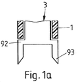
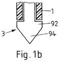
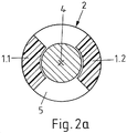
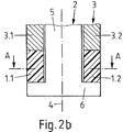
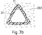
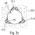
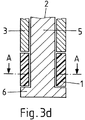
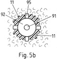
- 다공성 재료 내에 초기 개구를 제공하는 단계;- providing an initial opening in the porous material;
- 열가소성 보강 및/또는 라이닝 요소와 공구를 제공하는 단계;Providing thermoplastic reinforcement and / or lining elements and tools;
- 보강 및/또는 라이닝 요소를 초기 개구 내에 배치하고, 공구를 보강 및/또는 라이닝 요소의 단부 면과 접촉하도록 배치하며, 에너지가 공구에 결합되는 동안 그리고 공구와 보강 및/또는 라이닝 요소의 액화 계면의 주연부가 개구 내에 있는 동안 공구를 단부 면에 가압시키는 단계;Placing the reinforcement and / or lining element in the initial opening, placing the tool in contact with the reinforcement and / or the end face of the lining element, while the energy is coupled to the tool, and with the tool and the liquefying interface of the reinforcement and / Pressing the tool against the end face while the peripheral portion of the tool is in the opening;
- 이에 의해 액화 계면(들)에서 보강 및/또는 라이닝 요소의 열가소성 재료를 액화시켜 액화된 재료를 생성하는 단계;Thereby liquefying the thermoplastic material of the reinforcing and / or lining element at the liquefaction interface (s) to produce a liquefied material;
- 액화된 열가소성 재료의 일부분이 다공성 재료의 구조체 내로 침투하게 하는 단계;Causing a portion of the liquefied thermoplastic material to penetrate into the structure of the porous material;
- 액화된 열가소성 재료가 경화되어 보강 및/또는 라이닝 재료가 되도록 허용하는 단계; 및- allowing the liquefied thermoplastic material to cure to become a reinforcing and / or lining material; And
- 공구를 제거하는 단계- Steps to remove the tool
를 포함하고,Lt; / RTI >
하기의 조건, 즉The following conditions
a. 적어도 하나의 축방향 깊이에서, 이러한 축방향 깊이에서 초기 개구의 원주 방향 벽이 제1 영역에서 보강 및/또는 라이닝 요소와 접촉하고 제2 영역에서 보강 및/또는 라이닝 요소와 접촉하지 않도록 보강 및/또는 라이닝 요소가 원주 방향 각도의 함수로서 세그먼트화되는 조건;a. Or reinforcement and / or lining elements in the second region so that, at least at one axial depth, the circumferential wall of the initial opening at such axial depth is in contact with the reinforcement and / or lining element in the first region and / Or the condition that the lining element is segmented as a function of the circumferential angle;
b. 결과적으로 생성된 라이닝된 개구의 적어도 하나의 축방향 깊이에서, 보강 및/또는 라이닝 재료가 원주 방향 각도의 함수로서 세그먼트화되는 조건;b. A condition in which the reinforcing and / or lining material is segmented as a function of the circumferential angle, at at least one axial depth of the resulting lined opening;
c. 결과적으로 생성된 라이닝된 개구에서, 보강 및/또는 라이닝 재료가 서로 축방향으로 이격된 적어도 2개의 보강된 영역에 제공되고, 2개의 보강된 영역 사이에 비-보강된 영역이 있는 조건;c. In the resultant lined opening, the reinforcing and / or lining material is provided in at least two axially spaced reinforced regions, and there is a non-reinforced region between the two reinforced regions;
d. 보강 및/또는 라이닝 요소가 회전 실린더의 대칭을 갖지 않고 임의의 축을 중심으로 하는 회전에 대해 비대칭인 조건;d. A condition in which the reinforcement and / or lining element has no symmetry of the rotating cylinder and is asymmetric about rotation about any axis;
e. 공구가 보강 및/또는 라이닝 요소의 외측 연장 범위를 넘어 돌출되는(그리고 가능하게는 초기 개구의 원주 방향 벽을 넘어 다공성 재료 내로 돌출되는) 그리고 액화된 열가소성 재료의 유동을 소정 방위각으로 제한하는 적어도 하나의 반경 방향으로 돌출되는 블레이드를 포함하는 조건e. At least one (preferably at least one) of the lining elements and / or at least one of which protrudes beyond the outer extension of the lining element (and possibly protrudes beyond the circumferential wall of the initial opening) into the porous material and limits the flow of the liquefied thermoplastic material to a predetermined azimuth angle A condition including a radially projecting blade
중 적어도 하나가 충족된다.Is satisfied.
또한, 본 발명의 제1 태양에 따르면, 보강 및/또는 라이닝 요소와 공구를 포함하는 조립체가 제공되며, 이때 조립체는 전술된 방법을 수행할 수 있다.Also according to a first aspect of the present invention there is provided an assembly comprising a reinforcement and / or lining element and a tool, wherein the assembly can perform the method as described above.
본 명세서에서, 제1 태양 및 이하에 기술되는 제2 태양의 실시 형태는 때때로 세그먼트화된 보강 및/또는 라이닝의 실시 형태로 지칭된다.In this specification, the embodiments of the first and second aspects described below are sometimes referred to as embodiments of segmented reinforcement and / or lining.
초기 개구는 다공성 재료 내의 드릴링된 또는 천공된 구멍일 수 있거나, 다른 재료 제거 단계에 의해 다공성 재료에 형성되었을 수 있다. 대안적으로, 초기 개구는 재료 형성 단계에서, 예를 들어 다공성 재료를 포함하는 물체를 형상화하는 중에, 예를 들어 주조, 성형 또는 임의의 다른 재료 형상화 공정에 의해 제공되었을 수 있다. 또 다른 가능성에 따르면, 초기 개구는 이하에서 더욱 상세히 설명되는 바와 같이 기계적 진동에 의해 동력을 공급받는 공구에 의해 형성될 수 있다.The initial opening may be a drilled or perforated hole in the porous material, or it may have been formed in the porous material by another material removal step. Alternatively, the initial opening may have been provided in the material forming step, for example by casting, molding or any other material shaping process, during shaping of an object comprising, for example, a porous material. According to yet another possibility, the initial opening can be formed by a tool which is powered by mechanical vibrations as will be explained in more detail below.
공구의 제거 후에, 다공성 재료 내에 라이닝된 개구가 있을 것이며, 이러한 개구 내에 기계적 결합 요소(스크류와 같은) 또는 다른 결합 요소, 예를 들어 열 및/또는 전기 접점이 추후 단계에서 고정될 수 있다. 라이닝된 개구는 초기 개구의 측벽 내에 고정되는 보강 및/또는 라이닝 재료로 인해 단면의 잠재적인 약간의 감소를 갖고서 초기 개구에 상당할 수 있다. 대안적인 실시 형태에서, 라이닝된 개구가 적어도 소정 축방향 깊이에서(특히 더욱 근위의 위치에서) 초기 개구보다 큰 단면을 갖도록 초기 개구를 변형시키는 또 다른 단계가 방법의 일부일 수 있다. 그러나, 많은 실시 형태에서, 라이닝된 개구는 초기 개구보다 상당히 크지 않을 것이다.After removal of the tool there will be a lined opening in the porous material in which mechanical engaging elements (such as screws) or other engaging elements, such as heat and / or electrical contacts, may be secured at a later stage. The lined openings may correspond to an initial opening with some potential reduction in cross-section due to the reinforcement and / or lining material being secured within the side walls of the initial opening. In an alternative embodiment, another step of modifying the initial opening may be part of the process so that the lined opening has a cross-section that is larger than the initial opening at least at a predetermined axial depth (particularly at a more proximal position). However, in many embodiments, the lined opening will not be significantly larger than the initial opening.
예에서, 공구는 공구 샤프트와 근위측을 향하는 쇼울더를 형성하는 원위 확장부[풋(foot)]를 포함한다. 에너지가 공구에 결합되는 동안 공구를 근위 방향을 향해 끌어당김으로써 그리고/또는 보강 요소를 원위 방향을 향해 가압시킴으로써 쇼울더의 근위 방향 지향 표면이 보강 및/또는 라이닝 요소의 원위 단부 면에 가압될 수 있다. 이때, 액화 계면은 요소의 원위 단부 면과 확장부의 근위 방향 지향 표면 사이의 계면이다. 이것에서, 보강 및/또는 라이닝 요소는 공구 샤프트의 주연부에 배치될 수 있고, 그것은 공구 샤프트를 적어도 부분적으로 둘러쌀 수 있다. 이때, 공구가 끌어당겨지는 동안 대항력(counter force)을 가하기 위해 그리고/또는 보강 및/또는 라이닝 요소를 전방으로 가압시키기 위해 상대 요소(counter element)가 사용될 수 있다. 그러한 상대 요소는 예를 들어 역시 공구 샤프트를 적어도 부분적으로 둘러싸는 부싱과 같이 형성될 수 있거나, 또는 그것은 또한 다른 형상, 예를 들어 공구 샤프트가 그것을 통과하는 구멍을 갖춘 판의 형상을 가질 수 있다.In the example, the tool includes a distal extension [foot] which forms a shoulder facing the tool shaft and proximal side. The proximal-oriented surface of the shoulder can be pressed against the distal end surface of the reinforcing and / or lining element by pulling the tool toward the proximal direction and / or pressing the reinforcing element toward the distal direction while energy is coupled to the tool . Wherein the liquefied interface is the interface between the distal end surface of the element and the proximal orientation surface of the extension. In this, the reinforcement and / or lining element may be disposed at the periphery of the tool shaft, which may at least partially surround the tool shaft. At this time, a counter element may be used to apply a counter force while the tool is being pulled and / or to urge the lining element forward and / or for reinforcement. Such a counterpart element may, for example, be formed as a bushing at least partially surrounding the tool shaft, or it may also have the shape of a plate with another shape, for example a hole through which the tool shaft passes.
제1 태양의 다른 예에서, 또한 상대 요소의 역할을 할 수 있는 보조 요소가 보강 및/또는 라이닝 요소를 안내하기 위해 그리고/또는 대항력을 가하기 위해 사용된다. 보조 요소는 예를 들어 안내 샤프트와 근위측을 향하는 쇼울더를 형성하는 원위 확장부(풋)를 포함할 수 있으며, 이때 공구가 원위 방향을 향해 가압될 때 보강 및/또는 라이닝 요소의 원위 단부 면이 쇼울더에 가압될 수 있다.In another example of the first aspect, auxiliary elements that can also serve as counterpart elements are used to guide the reinforcement and / or lining elements and / or to exert counterforce. The auxiliary element may comprise, for example, a distal extension (foot) forming a shoulder facing proximal to the guide shaft, wherein the reinforcement and / or the distal end surface of the lining element when the tool is pressed towards the distal direction Can be pressed against the shoulder.
하기에서, 액화 중에, 인장력이 공구에 결합되고, 원위 방향을 향하는 대항력이 - 예를 들어 상대 요소에 의해 - 보강 및/또는 라이닝 요소에 결합되는 본 발명의 실시 형태가 때때로 '후방(rearward)' 구성으로 지칭되는 한편, 공구가 밀어내어지는 구성이 '전방(forward)' 구성이다.In the following, during liquefaction, embodiments of the present invention in which a tensile force is coupled to a tool and a counter-force directed in the distal direction is coupled to the lining element and / or to the lining element, for example by a counterpart element, Configuration, while the configuration in which the tool is pushed out is a " forward " configuration.
후방 구성에서(이는 모든 실시 형태 및 태양과 관련됨), 특히 공구에 결합되는 에너지가 기계적 진동 에너지이면, 공구는 케이블과 케이블에 부착되는 원위 요소를 포함할 수 있으며, 이때 원위 요소는 보강 및/또는 라이닝 요소의 원위 방향-지향 원위 커플링-인(coupling-in) 면과 접촉할 수 있는 근위 방향-지향 커플링-아웃(coupling-out) 면을 형성한다. 그러한 구성은 강성 공구에 의한 접근이 어려울 상황에서도 또한 물체를 보강 및/또는 라이닝하는 것을 가능하게 하고, 기계적 에너지의 편향이 가능해진다. 유사하게, 케이블이 적어도 하나의 가요성 방사선 전도체를 포함하거나 형성하면, 방사 에너지도 또한 이러한 방식으로 편향될 수 있다.In the rear configuration, which is related to all embodiments and aspects, particularly if the energy coupled to the tool is a mechanical vibration energy, the tool may comprise a distal element attached to the cable and the cable, wherein the distal element is reinforced and / Forming a proximal-oriented coupling-out surface that can contact the distal-oriented distal coupling-in surface of the lining element. Such a configuration also makes it possible to reinforce and / or lining the object, even in situations where it is difficult to access by a rigid tool, and it is possible to deflect the mechanical energy. Similarly, if the cable comprises or forms at least one flexible radiation conductor, the radiant energy can also be deflected in this manner.
조건 a.에서, 제2 영역은 상당하다. 예를 들어, 전체 원주의 적어도 60°, 또는 적어도 100°, 또는 심지어 적어도 180°가 제2 영역에 의해 점유된다. 조건 a.는 표면이 보강 및/또는 라이닝 재료를 갖는 제1 영역에 더하여, 또한 보강 및/또는 라이닝 재료가 없는 연장된 제2 영역을 포함하는 것을 의미한다.In condition a., The second area is significant. For example, at least 60 [deg.], Or at least 100 [deg.], Or even at least 180 [deg.] Of the entire circumference is occupied by the second region. Condition a. Means that the surface comprises an elongated second region which is in addition to the first region having a reinforcement and / or lining material, and which also lacks reinforcement and / or lining material.
조건 a.에서, 옵션에 따르면, 세그먼트화는 본질적으로 보강 및/또는 라이닝 요소의 전체 축방향 길이를 따라 진행되며, 즉 전체 축방향 길이를 따라 보강 및/또는 라이닝 재료가 없는(또는, 원주 방향 벽과 보강 및/또는 라이닝 요소 사이의 접촉이 없는) 원주 방향 각도가 있다. 특히, 보강 및/또는 라이닝 요소는 완전히 서로 분리되는 세그먼트를 포함할 수 있다. 대안적으로, 그러한 세그먼트는 예를 들어 근위 단부 및/또는 원위 단부에서 그것들을 연결하는 브리지 부분에 의해 연결될 수 있다. 그러한 브리지 부분은 상당하지 않도록 선택될 수 있으며, 즉 브리지 부분의 재료의 양은 브리지 부분 사이의 재료보다 훨씬 적도록(예를 들어 총량의 5% 미만 또는 3% 또는 2% 미만) 선택될 수 있다.According to the option, according to the option, the segmentation essentially proceeds along the entire axial length of the reinforcement and / or the lining element, that is to say without reinforcing and / or lining material along the entire axial length (or in the circumferential direction There is no contact between the wall and the reinforcing and / or lining elements). In particular, the reinforcing and / or lining elements may comprise segments that are completely separate from each other. Alternatively, such segments may be connected, for example, by a bridge portion connecting them at the proximal end and / or the distal end. Such a bridge portion can be selected to be non-significant, i.e. the amount of material in the bridge portion can be chosen to be much less than the material between the bridge portions (e.g. less than 5% or 3% or less than 2% of the total amount).
조건 b.에서, 원주를 따른 보강된 영역과 보강되지 않은 영역 사이의 분포는 본 방법과 사용되는 장치에 의해 결정되며, 즉 조직적이다. 이는 사용되는 장치 및/또는 사용되는 방법이 세그먼트화가 의도적인 방식으로 달성되도록 선택됨을 의미하며; 대부분의 경우에(기하학적 제약이 이를 막지 않는 한), 조작자는 삽입축을 중심으로 적절한 배향을 선택함으로써 보강된 영역과 보강되지 않은 영역이 최종적으로 위치되도록 의도되는 곳에 영향을 미칠 수 있다.In condition b., The distribution between the stiffened and unstiffened regions along the circumference is determined by the method and apparatus used, i.e. it is organized. This means that the device used and / or the method used are chosen such that the segmentation is achieved in an intentional manner; In most cases (as long as geometry constraints do not prevent this), the operator can influence where the reinforced and unreinforced areas are intended to be positioned ultimately by choosing the proper orientation around the insertion axis.
조건 b.를 충족시키는 방법은 제1 가능성에 따르면 조건 a.에 따른 세그먼트화된 보강 및/또는 라이닝 요소를 사용함으로써 달성될 수 있다. 제2 가능성에 따르면, 액화된 보강 및/또는 라이닝 재료가 다공성 재료 내로 침투하게 하는 단계 전에 형성되는 초기 개구는 라이닝된 개구의 기하학적 구조와 상이한 기하학적 구조를 가질 수 있다. 초기 개구는 예를 들어 라이닝된 개구와 상이한 대칭을 가질 수 있다. 액화된 보강 및/또는 라이닝 재료가 다공성 재료 내로 침투하게 하는 단계는 액화된 재료가 세그먼트화된 또는 비-세그먼트화된 방식으로 초기 개구의 측벽 내로 침투하게 하는 단계를 포함할 수 있다. 이러한 단계에 이어서, 보강 및/또는 라이닝 재료를 갖춘 다공성 재료가 제거되는 또 다른(초기 개구를 형성하는 것에 더하여) 재료 제거, 예를 들어 드릴링 단계가 수행되어, 라이닝된 개구가 조건 b.를 충족시킨다. 예를 들어, 보강 및/또는 라이닝 요소와 사용되는 공구[소노트로드(sonotrode) 및 가능하게는 보강 및/또는 라이닝 요소를 위한 안내 요소와 같은]는 상응하는 비-원형 대칭을 가질 수 있다.The method of satisfying the condition b. Can be accomplished by using a segmented reinforcing and / or lining element according to condition a according to the first possibility. According to a second possibility, the initial opening formed prior to the step of causing the liquefied reinforcement and / or lining material to penetrate into the porous material may have a geometry different from the geometry of the lined opening. The initial opening may have a different symmetry from, for example, the lined opening. The step of causing the liquefied reinforcement and / or lining material to penetrate into the porous material may include causing the liquefied material to infiltrate into the side walls of the initial opening in a segmented or non-segmented manner. Following this step, a material removal, e. G. Drilling, step (in addition to forming the initial opening) in which the porous material with the reinforcing and / or lining material is removed is performed so that the lined opening meets the condition b. . For example, a tool (such as a sonotrode and possibly a guiding element for reinforcing and / or lining elements) used with reinforcing and / or lining elements may have a corresponding non-circular symmetry.
따라서, 보강 후 생성되는 라이닝된 개구는 제1 가능성에 따르면 보강된 영역에서 추가된 보강 및/또는 라이닝 재료를 갖춘 초기 개구 다공성 재료일 수 있다. 제1 가능성과 조합될 수 있는 제2 가능성에 따르면, 결과적으로 생성되는 개구는 보강 및/또는 라이닝 재료를 갖춘 다공성 재료를 구비하는 초기 개구 내로의 드릴링에 의해 생성될 수 있다. 예를 들어, 초기 개구는 개구축에 대해 회전 대칭을 갖지 않을 수 있고, 보강 및/또는 라이닝 재료를 다공성 재료 내로 가압시키는 공정 후에, 보강 및/또는 라이닝 재료를 갖춘 다공성 재료가 소정 영역에서 제거되도록 또 다른 개구 형성 단계(예를 들어 드릴링 단계)가 수행될 수 있다. 또 다른 개구 형성 단계는 드릴과 같은, 원형 실린더형 보어를 형성하는 공구에 의해 수행될 수 있다.Thus, the lined opening created after reinforcement may be an initial apertured porous material with additional reinforcement and / or lining material in the reinforced area according to the first possibility. According to a second possibility that can be combined with the first possibility, the resulting opening can be created by drilling into an initial opening comprising a porous material with a reinforcing and / or lining material. For example, the initial opening may not have rotational symmetry with respect to the open construction, and after the process of pressing the reinforcing and / or lining material into the porous material, the porous material with the reinforcing and / or lining material may be removed Another opening forming step (e.g., a drilling step) may be performed. Another opening forming step may be performed by a tool forming a circular cylindrical bore, such as a drill.
조건 b.는 예를 들어 세그먼트화된 소노트로드에 의해, 위의 제2 가능성에 따른 재료 제거에 의해, 또는 복수의 보강 및/또는 라이닝 요소를 사용하는 것과 같은 다른 수단에 의해 그리고 개구를 형성하기 전이나 개구를 형성한 후에 달성될 수 있다.The condition b. May be determined, for example, by segmented small note load, by material removal according to the second possibility above, or by other means such as using a plurality of reinforcing and / or lining elements, Before or after forming the openings.
조건 c.에 대해, 예를 들어 전술된(세그먼트화가 있거나 없는) 또는 이하에 기술되는 바와 같은 보강 및/또는 라이닝 공정이 상이한 축방향 깊이에서 수행될 수 있다. 대안적으로, 근위측으로부터 접근가능한 개구를 갖춘 그리고 재료 출구 구멍을 갖춘 보조 요소가 사용될 수 있으며, 여기에서 재료 출구 구멍은 다공성 재료가 보강되는 위치를 규정한다. 다른 변형이 가능하다.For the condition c., For example, the abovementioned (with or without segmentation) or reinforcement and / or lining process as described below can be performed at different axial depths. Alternatively, an auxiliary element having an opening accessible from the proximal side and having a material outlet opening may be used, wherein the material outlet opening defines the location where the porous material is reinforced. Other variations are possible.
조건 c.에 따른 축방향 세그먼트화는 보강 및/또는 라이닝 공정이 재료에서의 특정 하중 또는 하중 전달 조건과 다공성 재료의 위치 특정적 특성에 맞추어질 수 있는 이점을 갖는다.The axial segmentation according to the condition c. Has the advantage that the reinforcement and / or lining process can be tailored to the specific load or load transfer conditions in the material and the position-specific properties of the porous material.
축방향 세그먼트화의 다른 적용에 따르면, 서로 축방향으로 이격되는 2개의 세그먼트화된 영역이 그것들 사이에 o-링 시일과 같은 밀봉 요소를 수용하기 위해 사용될 수 있다. 이때, 세그먼트화된 영역의 축방향 간격은 o-링 시일의 치수에 맞추어지며; 특히 그것은 o-링 시일의 직경보다 작다. 이러한 적용에 따르면, 특히, 개구의 보강된 및/또는 라이닝된 섹션의 직경은 초기 개구의(그리고 보강 및/또는 라이닝되지 않은 섹션의) 직경보다 작으며, 즉 보강 및/또는 라이닝 재료의 상당량이 공정 후 개구의 내부를 라이닝한다.According to another application of axial segmentation, two segmented regions axially spaced from one another can be used to accommodate a sealing element such as an o-ring seal therebetween. Wherein the axial spacing of the segmented regions is adapted to the dimensions of the o-ring seals; In particular it is smaller than the diameter of the o-ring seal. In particular, according to this application, the diameter of the reinforced and / or lined sections of the openings is smaller than the diameter of the initial openings (and of the reinforced and / or unlined sections), that is, The inside of the opening is lined after the process.
축방향 세그먼트화(또는 또한 원주 방향 세그먼트화)의 또 다른 적용에 따르면, 보강 및/또는 라이닝 재료는 예를 들어 중합체가 적절한 충전재를 구비함으로써 전기 전도성이도록 선택된다. 이것에서, 상이한 세그먼트가 비-보강된/라이닝된 섹션에 의해 또는 전기 절연 재료에 의해 보강/라이닝되는 섹션에 의해 서로 전기적으로 절연되는 상이한 전기 접점으로서 사용될 수 있다.According to another application of axial segmentation (or also circumferential segmentation), the reinforcing and / or lining material is chosen such that, for example, the polymer is electrically conductive by having a suitable filler. In this, different segments can be used as different electrical contacts that are electrically isolated from one another by the non-reinforced / lined section or by the sections reinforced / lined by the electrically insulating material.
조건 d.에 따르면, 보강 및/또는 라이닝 요소는 본질적으로 삼각형, 직사각형, 별 모양 등(모두 둥근 모서리를 갖는)인 외부 윤곽 형상(축에 수직한 단면에서)을 가질 수 있다. 원주 방향 세그먼트화(조건 b.를 충족시키기 위한)는 전술된 제2 태양에 따라 실린더형 구멍을 후속하여 드릴링함으로써 달성될 수 있으며, 이때 드릴은 보강 및/또는 라이닝 요소의 최소 외경보다 크지만 보강된 재료의 최대 외경보다 작은 직경을 갖는다.According to condition d. The reinforcement and / or lining elements may have an outer contour shape (in a cross-section perpendicular to the axis) that is essentially triangular, rectangular, star-shaped, etc. (all having rounded edges). Circumferential segmentation (to satisfy condition b.) Can be accomplished by subsequent drilling of the cylindrical bore according to the second aspect described above, wherein the drill is larger than the minimum outer diameter of the reinforcement and / or lining element, Lt; RTI ID = 0.0 > diameter. ≪ / RTI >
조건 e.에서, 보강 및/또는 라이닝 재료는 블레이드로 인해 공정 후 슬릿형성된 구조체를 얻는다. 조건 e.는 공구가 보강 및/또는 라이닝 공정 중에 끌어당겨지는 후방 구성에서 특히 유리하다.In condition e, the reinforcing and / or lining material obtains a slitted structure after processing due to the blades. Condition e. Is particularly advantageous in a posterior configuration in which the tool is pulled during the reinforcement and / or lining process.
조건 a. 내지 d. 모두는 서로, 즉 ab, ac, ad, bc, bd, cd, abc, abd, acd, bcd, 및 abcd로 조합될 수 있다. 또한, 이들 조건 모두의 조합과 그것들의 조건 e.와의 조합이 가능하며, 즉 ae, be, ce, de, abe, ace, ade, bce, bde, cde, abce, abde, acde, bcde, 및 abcde가 가능하다.Conditions a. D. All can be combined with each other, i.e. ab, ac, ad, bc, bd, cd, abc, abd, acd, bcd, and abcd. Also, it is possible to combine all these conditions and their conditions e., That is, ae, be, ce, de, abe, ace, ade, bce, bde, cde, abce, abde, acde, bcde, and abcde Is possible.
제2 태양에 따르면, 다공성 재료를 보강하는 보강 및/또는 라이닝 방법은:According to a second aspect, a method of reinforcing and / or lining a porous material to reinforce comprises:
적어도 하나의 열가소성 보강 및/또는 라이닝 요소를 제공하는 단계;Providing at least one thermoplastic reinforcing and / or lining element;
보강 및/또는 라이닝 요소를 다공성 재료와 접촉하도록 배치하고, 기계적 에너지가 보강 및/또는 라이닝 요소에 인가되게 하여 보강 및/또는 라이닝 요소의 적어도 일부분을 액화시키며, 보강 및/또는 라이닝 요소의 액화된 보강 및/또는 라이닝 재료 부분이 다공성 재료 내로 침투하게 하는 단계;Or reinforcement and / or lining elements are placed in contact with the porous material, mechanical energy is applied to the reinforcing and / or lining elements to liquefy and / or liquefy at least a portion of the lining elements, and the liquefied and / Causing the reinforcement and / or lining material portion to penetrate into the porous material;
액화된 보강 및/또는 라이닝 재료 부분이 재고화되게 놓아두는 단계; Leaving the liquefied reinforcement and / or lining material portion stocked;
다공성 재료 및 재고화된 보강 및/또는 라이닝 재료의 일부분을 제거하여 라이닝된 개구를 얻는 단계로서, 라이닝된 개구는 재고화된 보강 및/또는 라이닝 재료를 갖춘 다공성 재료의 표면 부분을 구비하고 재고화된 보강 및/또는 라이닝 재료가 없는 다공성 재료의 표면 부분을 구비하는 단계Removing the porous material and a portion of the stocked reinforcing and / or lining material to obtain a lined opening, wherein the lined opening has a surface portion of the porous material with an in- stalled reinforcement and / or lining material, Comprising a surface portion of a porous material free of reinforcing and / or lining material
를 포함한다..
제거하는 단계는 드릴과 같은, 원형 실린더형 보어를 형성하는 공구에 의해 수행될 수 있다. 밀링 공구 또는 유사한 것에 의한 비-실린더형 기하학적 구조도 또한 가능하다.The step of removing can be performed by a tool forming a circular cylindrical bore, such as a drill. Non-cylindrical geometries by milling tools or the like are also possible.
제1 군의 실시 형태에서, 액화된 보강 및/또는 라이닝 재료가 다공성 재료 내로 침투하게 하는 단계 전에, 라이닝된 개구의 기하학적 구조와 상이한 기하학적 구조의 초기 개구가 제공되며, 이때 초기 개구는 예를 들어 라이닝된 개구와 상이한 대칭을 갖는다. 이어서, 액화된 보강 및/또는 라이닝 재료가 다공성 재료 내로 침투하게 하는 단계는 액화된 재료가 초기 개구의 측벽 내로 침투하게 하는 단계를 포함할 수 있다. 예를 들어, 보강 및/또는 라이닝 요소와 사용되는 공구(소노트로드 및 가능하게는 보강 및/또는 라이닝 요소를 위한 안내 요소와 같은)는 상응하는 비-원형 대칭을 가질 수 있다.In the first group of embodiments, prior to the step of causing the liquefied reinforcement and / or lining material to penetrate into the porous material, an initial opening of the geometric structure that is different from the geometry of the lined opening is provided, And has a different symmetry from the lined opening. The step of causing the liquefied reinforcement and / or lining material to penetrate into the porous material may then include causing the liquefied material to penetrate into the sidewalls of the initial opening. For example, tools used with reinforcing and / or lining elements (such as small note rods and possibly guide elements for reinforcement and / or lining elements) may have corresponding non-circular symmetries.
이어서, 다공성 재료 및 재고화된 보강 및/또는 라이닝 재료의 일부분을 제거하는 후속 단계는 보강 및/또는 라이닝 재료를 세그먼트로 분할할 수 있으며, 이때 재고화된 보강 및/또는 라이닝 재료가 없는 다공성 재료의 표면 부분이 세그먼트 사이에 있다.Subsequent steps of removing the porous material and a portion of the stocked reinforcing and / or lining material may then divide the reinforcing and / or lining material into segments, wherein the porous material without reinforcement and / or lining material The surface portion of which is between the segments.
제2 군의 실시 형태에서, 보강 및/또는 라이닝 요소 또는 복수의 보강 및/또는 라이닝 요소는 전체적으로 본 명세서에 참고로 포함되는 US 6,913,666 또는 US 7,160,405에 기술된 바와 같은 방법에 의해 다공성 재료 내에 고정될 수 있다. 예를 들어, 복수의 본질적으로 핀-같은 보강 및/또는 라이닝 요소가 사용될 수 있다. 보강 및/또는 라이닝 요소는 추후 추가되는 라이닝된 개구에 대해 주변에 있는 위치에 고정된다. 이어서, 라이닝된 개구가 형성되며, 이때 라이닝된 개구는 예를 들어 실린더형 또는 원추형이거나 타원형 또는 임의의 다른 형상을 갖는다.In a second group of embodiments, the reinforcing and / or lining element or the plurality of reinforcing and / or lining elements are fixed within the porous material by a method as described in US 6,913,666 or US 7,160,405, which is incorporated herein by reference in its entirety. . For example, a plurality of essentially pin-like reinforcement and / or lining elements may be used. The reinforcement and / or lining element is fixed in a position in the periphery with respect to the later added lined opening. A lined opening is then formed, wherein the lined opening has, for example, a cylindrical or conical shape, an elliptical shape or any other shape.
제1 및/또는 제2 태양의 실시 형태에서, 초기 개구 및/또는 최종의 라이닝된 개구가 계단형일 수 있으며, 즉 그것의 단면이 축방향 위치에 대한 단면의 계단-같은 의존성을 갖고서 깊이의 함수로서 변할 수 있다.In an embodiment of the first and / or the second aspect, the initial opening and / or the final lined opening may be stepped, that is to say that its cross-section has a step-like dependence of the cross- Lt; / RTI >
본 발명의 제1 및/또는 제2 태양의 실시 형태는 위에 설명된 적용에 적합한 것에 대한 대안으로서 또는 그것에 더하여 하기의 이점을 제공할 수 있다: 인접한 관형 보강 및/또는 라이닝 요소에 의한 비-세그먼트화된 보강 및/또는 라이닝이 다공성 재료에서 도넛형(toroidal) 보강 및/또는 라이닝 재료 분포를 생성할 것이다. 이어서 스크류가 보강된 초기 개구 내에 스크류 체결되면, 재료가 상당한 저항을 받을 것이며, 이는 다공성 재료 내의 전체 도넛형 보강 및/또는 라이닝 재료 링의 비틀림 운동을 초래하여, 취약한 다공성 재료의 손상을 초래할 수 있다. 이와 대조적으로, 세그먼트화된 보강 및/또는 라이닝 재료는 다공성 재료의 잔류 탄성으로 인해 어느 정도 구부러질 수 있으며, 이는 스크류의 스크류 체결을 용이하게 할 것임과 동시에, 보강 및/또는 라이닝에 의해 제공되는 추가의 안정성의 이익이 얻어질 수 있다.Embodiments of the first and / or the second aspect of the present invention may offer the following advantages as alternatives to or in addition to being suited to the applications described above: The use of adjacent tubular reinforcement and / or non- The reinforced reinforcement and / or lining will create a toroidal reinforcement and / or a lining material distribution in the porous material. Then, when the screw is screwed into the reinforced initial opening, the material will be subjected to substantial resistance, which may result in an overall toroidal reinforcement in the porous material and / or a tortuous movement of the lining material ring, resulting in damage to the porous porous material . In contrast, the segmented reinforcing and / or lining material can be bent to some extent due to the residual resilience of the porous material, which will facilitate screwing of the screw and, at the same time, An additional benefit of stability can be obtained.
본 발명의 제3 태양에 따르면, 다공성 재료를 보강하는 방법이 제공되며, 이러한 방법은 스크류 또는 다른 결합 요소의 삽입 후에 다공성 재료를 보강하는 단계를 포함한다. 이를 위해, 결합 요소의 삽입 후에(예를 들어 종래에는 구멍을 드릴링한 다음에 결합 요소를 구멍 내로 압입하거나 스크류 체결함으로써), 적어도 하나의 보강 및/또는 라이닝 요소가 에너지의 충격 하에 다공성 재료 내에 고정되어 결합 요소와 접촉한다. 결합 요소와 보강 및/또는 라이닝 요소는 제1 가능성에 따르면 그것들이 공정 후 상호로킹되도록 하는 구조체를 포함할 수 있으며, 예를 들어 결합 요소와 보강 및/또는 라이닝 요소 중 하나는 액화가능한 재료를 포함할 수 있고, 다른 하나는 액화가능한 재료가 그것 내로 침투하여 확고한-맞춤 연결(positive-fit connection)을 생성할 수 있는 구조체를 포함할 수 있다. 제2 가능성에 따르면, 결합 요소와 보강 및/또는 라이닝 요소 둘 모두는 보강 및/또는 라이닝 요소가 결합 요소에 용접가능하도록 열가소성 재료를 포함한다.According to a third aspect of the present invention, there is provided a method of reinforcing a porous material, the method comprising the step of reinforcing the porous material after insertion of a screw or other engagement element. To this end, at least one of the reinforcing and / or lining elements may be fixed within the porous material after the insertion of the coupling element (e.g., conventionally by drilling the hole and then pushing or screwing the coupling element into the hole) And is in contact with the coupling element. The coupling element and the reinforcing and / or lining element may comprise a structure that allows them to be mutually locked after processing according to a first possibility, for example one of the coupling element and the reinforcing and / or lining element comprises a liquefiable material And the other may include a structure that allows the liquefiable material to penetrate into it to create a positive-fit connection. According to a second possibility, both the engaging element and the reinforcing and / or lining element comprise a thermoplastic material such that the reinforcing and / or lining element is weldable to the engaging element.
제4 태양의 방법에 따르면, 보강 및/또는 라이닝 방법은:According to the method of the fourth aspect, the method of reinforcing and / or lining comprises:
- 다공성 재료 내에 초기 개구를 제공하는 단계;- providing an initial opening in the porous material;
- 열가소성 보강 및/또는 라이닝 요소(예를 들어 슬리브 벽을 갖춘 슬리브임)를 제공하고, 공구(예를 들어 소노트로드)와 보조 요소를 추가로 제공하는 단계;Providing a thermoplastic reinforcement and / or lining element (e.g. a sleeve with a sleeve wall) and further providing a tool (e. G. A small note load) and ancillary elements;
- 보강 및/또는 라이닝 요소를 초기 개구 내에 배치하는 단계로서, 보강 및/또는 라이닝 요소는 공구 또는 보조 요소의 안내 부분을 적어도 부분적으로 둘러싸는 단계;Placing the reinforcement and / or lining element in an initial opening, the reinforcement and / or lining element at least partially surrounding the guide portion of the tool or auxiliary element;
- 보강 및/또는 라이닝 요소의 일부분이 개구 내에 있고 다공성 재료와 접촉하는 동안 가압력과 에너지를 공구에 그리고 공구로부터 보강 및/또는 라이닝 요소에 결합시키는 단계;- bonding the pressing force and energy to the tool and from the tool to the reinforcing and / or lining element while the part of the reinforcing and / or lining element is in the opening and in contact with the porous material;
- 이에 의해 보강 및/또는 라이닝 요소의 재료를 액화시켜 액화된 재료를 생성하는 단계;Thereby liquefying the material of the reinforcing and / or lining elements to produce a liquefied material;
- 액화된 재료의 일부분이 다공성 재료의 구조체 내로 그리고/또는 다공성 재료에 연결된 요소의 구조체 내로 침투하게 하는 단계;Causing a portion of the liquefied material to penetrate into the structure of the porous material and / or into the structure of the element connected to the porous material;
- 액화된 재료가 경화되어 보강 및/또는 라이닝 재료가 되도록 허용하는 단계; 및- allowing the liquefied material to cure to become a reinforcing and / or lining material; And
- 공구를 제거하는 단계- Steps to remove the tool
를 포함하고,Lt; / RTI >
하기의 조건, 즉The following conditions
A. 가압력과 에너지를 공구에 결합시키는 단계 중에, 외측 보호 요소가 공구를 적어도 부분적으로 둘러싸고, 공구가 다공성 재료와 접촉하지 못하도록 국소적으로 방지하는 조건;A. conditions during which the outer protective element at least partially surrounds the tool and prevents the tool from contacting the porous material during the step of bonding the pressing force and energy to the tool;
B. 보강 및/또는 라이닝 요소가 대체로 슬리브형이고, 슬리브 벽 내에 적어도 하나의 함입부 또는 구멍을 포함하는 조건;B. the condition that the reinforcing and / or lining element is generally sleeve-like and includes at least one recess or hole in the sleeve wall;
C. 가압력과 에너지를 공구에 결합시키는 단계 중에, 텔레스코핑(telescoping) 영역에서, 공구의 일부분이 보조 요소의 일부분을 둘러싸거나, 또는 보조 요소의 일부분이 공구를 둘러싸고, 공구 및/또는 보조 요소가 각각 보조 요소/공구를 향하는 적어도 하나의 돌출부를 포함하여, 텔레스코핑 영역에서, 돌출부/돌출부들을 제외하고는, 공구와 보조 요소 사이의 접촉이 방지되는 조건;C. During the step of bonding the pressing force and energy to the tool, in a telescoping area, a part of the tool surrounds a part of the auxiliary element, or a part of the auxiliary element surrounds the tool, and the tool and / A condition in which, in the telescoping region, the contact between the tool and the auxiliary element is prevented, except for the protrusions / protrusions, including at least one protrusion facing the respective auxiliary element / tool;
D. 가압력과 에너지를 공구에 결합시키는 단계 중에, 공구가 원위 방향을 향해 가압되고, 공구가 돌출 특징부의 근위의 위치에서 공구와 다공성 재료 사이의 접촉을 방지하는 상기 돌출 특징부를 형성하는 원위 확장부를 포함하는(즉, 공구의 직경이 돌출 특징부를 제외하고는 초기 개구의 직경에 비해 감소됨) 조건;D. During the step of joining the pressing force and the energy to the tool, the tool is pressed towards the distal direction and the distal extension portion forming the protruding feature preventing the tool from contacting between the tool and the porous material at the proximal position of the protruding feature (I. E., The diameter of the tool is reduced relative to the diameter of the initial opening except for the protruding feature);
E. 가압력과 에너지를 공구에 결합시키는 단계 전에, 보강 및/또는 라이닝 요소가 축방향 확고한-맞춤 연결에 의해 공구에 연결되고, 가압력과 에너지를 공구에 결합시키는 단계 중에, 보조 요소가 원위 방향을 향해 가압되어, 보강 및/또는 라이닝 요소의 재료를 액화시키는 단계를 활성화시키고, 액화된 재료의 일부분을 옆으로 그리고 다공성 재료의 구조체 내로 가압시키는 조건E. Prior to the step of engaging the pressing force and energy to the tool, the reinforcing and / or lining element is connected to the tool by an axially rigid-fitting connection, and during the step of coupling the pressing force and energy to the tool, To activate the step of liquefying the material of the reinforcement and / or the lining element, and pressing a portion of the liquefied material laterally and into the structure of the porous material
중 적어도 하나가 충족된다.Is satisfied.
적어도 이들 조건의 하기의 조합, 즉 AB, AC, ABC, BC, BD, BCD, CD, CDE, DE가 가능하고, 본 발명의 또 다른 실시 형태이다. 또한, 특정 구성에서, BE, BCE, 및 BCDE도 또한 가능하다.At least the following combinations of these conditions are possible: AB, AC, ABC, BC, BD, BCD, CD, CDE, DE. Also, in certain configurations, BE, BCE, and BCDE are also possible.
이것에서 그리고 본 발명의 다른 태양에서 그리고 이하에서 추가로 설명되는 바와 같이, 에너지는 기계적 진동의 형태로 공구에(그리고 그것으로부터 보강 및/또는 라이닝 요소에) 결합될 수 있다. 따라서, 에너지가 기계적 진동 에너지이면, 공구는 기계적 진동 및/또는 이들 진동으로부터 흡수되는 열을 보강 및/또는 라이닝 요소에 결합시키기 위한 소노트로드이다.In this and in other aspects of the invention and as will be explained further below, energy can be coupled (and from the reinforcement and / or lining element) to the tool in the form of mechanical vibrations. Thus, if the energy is mechanical vibration energy, the tool is a small knot rod for coupling mechanical vibration and / or heat absorbed from these vibrations to the reinforcing and / or lining element.
대안적으로, 에너지는 보강 및/또는 라이닝 요소에 의해 흡수되는 방사선(특히 레이저 방사선)에 의해 공구에 결합될 수 있다. 또 다른 대안으로서, 에너지는 기계적 진동과 상이한 기계적 에너지, 예를 들어 회전일 수 있다. 또 다른 대안으로서, 에너지는 예를 들어 열 전도에 의해 그리고/또는 보강 및/또는 라이닝 요소가 비교적 높은 전기 저항을 갖는 전기 전도 재료를 포함하는 동안 전류가 보강 및/또는 라이닝 요소를 통해 흐르게 함으로써 보강 및/또는 라이닝 요소로 지향되는 열일 수 있다.Alternatively, the energy can be coupled to the tool by radiation (especially laser radiation) that is absorbed by the reinforcement and / or lining elements. As yet another alternative, energy may be mechanical energy, such as rotation, that is different from mechanical vibration. Alternatively, the energy may be reinforced, for example by flowing current through the reinforcing and / or lining element, for example by thermal conduction and / or while the reinforcing and / or lining element comprises an electrically conductive material having a relatively high electrical resistance And / or a lining element.
조건 A에서, 외측 보호 요소는 공구와 보호 요소 사이의 마찰을 최소화시키기에 적합한 표면 특성을 갖는 적합한 재료의 슬리브일 수 있다. 특히, 그것은 얇은 슬리브일 수 있으며, 이때 재료 두께는 단지 보호 요소가 치수적으로 강경하도록 하기에 충분하다. 보호 요소는 공구가 보호 요소의 장소에서 국소적으로 다공성 재료와 접촉하지 못하도록 방지한다. 다른 장소에서는, 상황에 따라 공구와 다공성 재료 사이의 직접적인 접촉이 일어날 수 있다.In Condition A, the outer protective element may be a sleeve of a suitable material having surface properties suitable for minimizing friction between the tool and the protective element. In particular, it may be a thin sleeve, wherein the thickness of the material is sufficient only to render the protective element dimensionally rigid. The protective element prevents the tool from locally contacting the porous material at the location of the protective element. In other places, direct contact between the tool and the porous material may occur, depending on the situation.
조건 A에서, 선택적으로 보호 요소는 나사 태핑(tapping) 기능을 포함할 수 있다.In condition A, optionally the protective element may comprise a screw tapping function.
조건 B에서, 보강 및/또는 라이닝 요소는 조직적인 약화부인 함입부, 구멍 등을 갖춘 대체로 슬리브형일 수 있다. 이들 약화부 - 보강 및/또는 라이닝 요소의 목적 및/또는 보강될 다공성 재료의 치수/기하학적 특성에 맞추어지는 공간으로서 배치될 수 있는 - 로 인해, 보강 및/또는 라이닝 재료는 보다 작은 에너지 충격으로 액화될 수 있다. 보강 및/또는 라이닝 요소에 인가되는 동력의 함수로서 액화의 개시는 이미 보다 낮은 동력에 있으며, 따라서 액화에 보다 작은 동력이 필요하다. 실시 형태에서, 약화부는 반경 방향에 대해 경사지는 홈이다. 홈은 에너지가 인가될 때 액화가 시작되는 보강 및/또는 라이닝 요소 재료 내의 목부를 규정한다. 목부(또는 다른 약한 점)에서의 액화 후에, 나머지 부분이 홈에 의해 규정되는 방향을 따라 전단 운동을 받을 수 있다. 실시 형태에서, 홈은 공구가 그것들을 원위 방향을 향해 가압시킬 때 더욱 근위의 부분이 외향으로 가압되도록 한다.In condition B, the reinforcing and / or lining element may be of a generally sleeve type with a recessed portion, hole, etc. which is a tissue weakening portion. The reinforcement and / or lining material may be liquefied and / or liquefied with a smaller energy impact due to these weakening-reinforcement and / or lining elements' purposes and / or they may be arranged as spaces tailored to the dimensional / geometric characteristics of the porous material to be reinforced . The commencement of liquefaction as a function of the power applied to the reinforcement and / or lining elements is already of lower power and therefore requires less power for liquefaction. In an embodiment, the weakened portion is a groove that is inclined with respect to the radial direction. The grooves define the neck in the reinforcing and / or lining element material from which liquefaction begins when energy is applied. After liquefaction at the throat (or other weak point), the remaining portion may be subjected to shear motion along a direction defined by the grooves. In an embodiment, the grooves allow the more proximal portion to be pressed outward when the tool presses them toward the distal direction.
모든 태양의 실시 형태에서, 보강 및/또는 라이닝 요소와 접촉하는 그리고 그것을 통해 기계적 에너지가 보강 및/또는 라이닝 요소에 결합되는 공구(예를 들어 에너지가 기계적 진동을 통해 인가되면 소노트로드)의 표면은 대체로 평평할(방사상, 즉 근원축에 수직함) 수 있거나, 테이퍼지거나 임의의 다른 형상을 가질 수 있다. 특히 유리한 조합은 조건 B를 충족시키는 보강 및/또는 라이닝 요소와 평평한 공구 접촉면의 조합이다. 이의 하나의 이유는 표면이 평평할 때 공구의 설계와 취급이 더욱 쉬운 한편, 조건 B가 충족되면 비-평평한 접촉면의 이점(즉, 액화의 직접적인 표적화된 개시, 액화된 재료의 다공성 재료 내로의 변위)이 또한 달성될 수 있다는 것이다.In all of the embodiments, the surface of the tool contacting and / or mechanically energized with the reinforcement and / or lining element (e. G., A small note rod when energy is applied through mechanical vibration) May be generally flat (radial, i.e., orthogonal to the origin axis), tapered, or have any other shape. A particularly advantageous combination is the combination of a reinforcing and / or lining element and a flat tool contact surface that satisfy condition B. One reason for this is that the tool is easier to design and handle when the surface is flat, while the advantage of a non-flat contact surface (i.e., direct targeted initiation of liquefaction, displacement of the liquefied material into the porous material ) Can also be achieved.
조건 C에서, 텔레스코핑 영역(공구와 보조 요소가 활주 접촉하는 곳)에서, 공구는 (축방향 및/또는 원주 방향) 리지, 구 등과 같은 내향 돌출부를 포함할 수 있다. 추가 또는 대안으로서, 보조 요소는 상응하는 외향 돌출부를 포함할 수 있다. 이들 돌출부로 인해, 용적부[완충 용적부(buffer volume)]가 공구와 보조 요소 사이에 형성되어, 돌출부를 제외하고는, 그것들이 서로 접촉하지 않는다. 이는 에너지 손실, 소음(에너지가 기계적 에너지, 예를 들어 진동 에너지이면) 및 특히 마찰에 의해 발생되는 열을 감소시켜, 공정의 효율을 증가시킨다. 돌출부는 액화된 재료가 완충 용적부 내로 침투하지 않도록 할 수 있다. 이는 예를 들어 보강 및/또는 라이닝 요소에 대한 계면에서 공구와 보조 요소 사이의 임의의 잔류 갭이 표면 장력과 중합체의 열 흐름 유발 급랭이 액화된 재료가 그러한 갭 내로 유입되지 못하게 방지하도록 충분히 작다는 것에 의해 보장될 수 있다. 전형적으로, 갭 크기에 대한 상한은 낮은 용융 점도의 중합체(예컨대, 비정질 지방족 폴리에스테르, 액정 중합체)에 대해 0.05 내지 0.1 mm이거나 보다 높은 용융 점도를 갖는 중합체(예컨대, 보다 높은 분자량의 폴리프로필렌)에 대해 최대 0.2 mm이다. 최적 갭 폭은 간단한 크기 변화 실험으로 결정될 수 있다.In condition C, at the telescoping area (where the tool and the auxiliary element slide into contact), the tool may include inward projections such as ridges, sills, and the like (axial and / or circumferential). Additionally or alternatively, the ancillary elements may include corresponding outwardly projecting portions. Due to these protrusions, a volume portion (buffer volume) is formed between the tool and the auxiliary element, so that they do not contact each other except for the protrusions. This reduces the energy loss, the noise (if energy is mechanical energy, for example vibrational energy) and especially the heat generated by friction, thus increasing the efficiency of the process. The protrusions can prevent the liquefied material from penetrating into the buffer volume. This means that any residual gap between the tool and the auxiliary element at the interface to the reinforcement and / or lining element, for example, is sufficient to prevent surface tension and heat flow induced quenching of the polymer from being sufficiently small to prevent liquefied material from entering the gap Can be assured by one. Typically, the upper limit for the gap size is from 0.05 to 0.1 mm or higher for polymers with low melt viscosities (such as amorphous aliphatic polyesters, liquid crystalline polymers) or polymers with a higher melt viscosity (e.g., higher molecular weight polypropylene) For a maximum of 0.2 mm. The optimum gap width can be determined by a simple size change experiment.
위로부터, 표면 장력이 액화된 재료가 그러한 갭 내로 유입되지 못하게 방지하도록 갭이 0.2 mm보다 작으면 흔히 유리하다.From above, it is often advantageous if the gap is less than 0.2 mm so that the surface tension prevents the liquefied material from flowing into such a gap.
특히, 일 실시 형태에서, 공구는 내향으로 돌출되는 원위 원주 방향 리지를 포함한다. 다른 실시 형태에서, 공구 및/또는 보조 요소는 동일하거나 상이한 형상을 비롯하여, 칼로트(calotte)형, 원추형이거나 다른 형상을 가질 수 있는 복수의 미세-돌출부 또는 복수의 축방향 리지를 포함한다.In particular, in one embodiment, the tool includes a distal circumferential ridge projecting inwardly. In other embodiments, the tool and / or auxiliary element includes a plurality of micro-projections or a plurality of axial ridges, which may have the same or different shape, and may have a calotte, cone or other shape.
조건 D에서, 공구는 조건 C에 의해 규정되는 돌출부에 더하여 또는 그것에 대한 대안으로서, 공구의 몸체가 다공성 재료와 직접적으로 접촉하지 못하게 하는 적어도 하나의 외향 돌출부를 포함한다. 특히, 그러한 외향 돌출부는 본질적으로 공구의 원위 단부에 그리고 보조 요소에 대한 계면에 위치되어, 액화된 재료가 다공성 재료 내로 가압되는 대신에 다공성 재료를 따라 역류하지 못하도록 방지할 수 있다.In condition D, the tool comprises at least one outward protrusion which prevents the body of the tool from coming into direct contact with the porous material, in addition to or as an alternative to the protrusion defined by condition C. In particular, such outward protrusions are essentially located at the distal end of the tool and at the interface with the ancillary elements to prevent the liquefied material from flowing back along the porous material instead of being pushed into the porous material.
모든 다른 실시 형태에서와 같이, 조건 D의 특징은 경사진 원위 공구 표면과 조합될 수 있다.As in all other embodiments, the features of condition D can be combined with the inclined distal tool surface.
조건 E에서, 확고한-맞춤 연결은 예를 들어 공구의 수나사(outer thread)에 의해 또는 제조 공정 중에 보강 및/또는 라이닝 재료가 그것 상에 주조되었던 원주 방향으로 연장되는 함입부에 의해 제공될 수 있다. 조건 E에 따라 진행할 때, 조작자는 공구가 정지되어 유지되거나 근위 방향을 향해 천천히 후퇴되거나 또한 원위 방향으로 천천히 이동되는(보조 요소보다 느리게) 동안 보조 요소를 원위 방향으로 전진시킬 수 있다.In condition E, the firm-fit connection can be provided by a circumferentially extending recess, for example by means of an outer thread of the tool or during the manufacturing process, in which the reinforcement and / or the lining material has been cast on it . When proceeding in accordance with condition E, the operator can advance the auxiliary element in the distal direction while the tool is stopped and held or slowly retracted toward the proximal direction or also slowly moved (slower than the auxiliary element) in the distal direction.
조건 E는 중앙 공구와 주변 보조 요소를 갖는 구성으로 인해, 초기 개구를 포위하는 다공성 재료와 공구 사이에 단지 최소의 접촉만이 있는 제1 이점을 특징으로 한다. 그것은 보강 및/또는 라이닝 요소가 공구에 결합되는 또 다른 이점을 특징으로 한다. 따라서, 에너지가 기계적 에너지이면, 보강 및/또는 라이닝 요소는 - 공구가 예를 들어 보강 및/또는 라이닝 요소를 '해머링(hammering)'하는 구성과 대조적으로 - 완전한 (진동, 회전) 운동을 받는다. 이는 발생되는 소음 및 액화에 필요한 에너지의 추가의 감소를 가져온다. 또한, 에너지가 기계적 에너지가 아니라 예를 들어 방사 에너지 또는 열인 실시 형태에서, 이러한 직접적인 접촉은 특히 보강 및/또는 라이닝 요소로의 원하는 에너지 전달을 최적화시키는데 유리할 수 있다.Condition E is characterized by the first advantage of having only minimal contact between the tool and the porous material surrounding the initial opening due to the configuration with the central tool and peripheral auxiliary elements. It is characterized by another advantage that the reinforcement and / or lining elements are coupled to the tool. Thus, if the energy is mechanical energy, the reinforcement and / or lining elements are subjected to a complete (oscillating, rotating) motion, as opposed to a configuration in which the tool 'hammers' the reinforcement and / or lining elements. This results in an additional reduction in the noise generated and the energy required for liquefaction. Also, in embodiments where the energy is not mechanical energy, for example radiant energy or heat, such direct contact may be advantageous, in particular, to optimize the desired energy transfer to the reinforcement and / or lining elements.
추가 또는 대안으로서, 소음 감소를 위한 다른 조치가 취해질 수 있다. 일례로서, 소노트로드 및/또는 보조 요소의 재료는 그것이 공진체(resonating body)를 형성하지 않을 수 있고 - 선택된 주파수와 치수를 고려하여 - 본질적으로 강체(stiff body)로 고려되게 의도되도록 선택될 수 있다. 그러한 재료의 일례는 금속 대신에 PEEK이다. 다른 예는 폴리테트라플루오로에틸렌(PTFE), 폴리이미드 등과 같은 또 다른 고온 용융 중합체를 포함한다.In addition or as an alternative, other measures for noise reduction may be taken. As an example, the material of the small note rod and / or the auxiliary element may be selected such that it may not form a resonating body and is intended to be considered essentially a stiff body, taking into account the selected frequencies and dimensions . An example of such a material is PEEK instead of metal. Other examples include another hot melt polymer such as polytetrafluoroethylene (PTFE), polyimide, and the like.
본 발명의 또 다른 제5 태양에 따르면, 다공성 재료를 보강하는 방법이 제공되며, 이러한 방법은:According to a fifth aspect of the present invention, there is provided a method of reinforcing a porous material, comprising:
- 천공 팁 및/또는 커팅 에지를 갖춘 원위 단부를 포함하는 공구 또는 상대 요소를 제공하는 단계;Providing a tool or counterpart comprising a distal end with a piercing tip and / or a cutting edge;
- 열가소성 보강 및/또는 라이닝 요소를 제공하는 단계;- providing thermoplastic reinforcement and / or lining elements;
- 원위 단부를 갖춘 공구 또는 상대 요소를 다공성 재료와 접촉하도록 배치하고, 기구 또는 상대 요소를 다공성 재료에 가압시켜 공구 또는 상대 요소를 다공성 재료 내로 가압시키는 단계;Placing a tool or a mating element having a distal end in contact with the porous material and pressing the tool or mating element against the porous material to press the tool or mating element into the porous material;
- 보강 및/또는 라이닝 요소를 공구 또는 상대 요소의 면과 접촉하도록 배치하는 단계로서, 면은 근위측을 향하는 단계;- disposing the reinforcement and / or lining element in contact with the surface of the tool or the mating element, the surface facing towards the proximal side;
- 에너지가 보강 및/또는 라이닝 요소에 결합되는 동안 공구 또는 상대 요소를 보강 및/또는 라이닝 요소에 맞대어 근위 방향을 향해 유지시키는 단계;Maintaining the tool or the mating element against the reinforcing and / or lining element and toward the proximal direction while energy is coupled to the reinforcing and / or lining element;
- 이에 의해 보강 및/또는 라이닝 요소의 재료를 액화시켜 액화된 재료를 생성하는 단계;Thereby liquefying the material of the reinforcing and / or lining elements to produce a liquefied material;
- 액화된 재료의 일부분이 다공성 재료의 구조체 내로 침투하게 하는 단계;Causing a portion of the liquefied material to penetrate into the structure of the porous material;
- 액화된 재료가 경화되어 보강 및/또는 라이닝 재료가 되도록 허용하는 단계; 및- allowing the liquefied material to cure to become a reinforcing and / or lining material; And
- 기구를 제거하는 단계- steps to remove the instrument
를 포함한다..
이것에서, 공구 또는 상대 요소를 다공성 재료에 가압시키는 단계 중에, 동시에 기계적 에너지가 각각 공구 또는 상대 요소에 결합될 수 있다.In this way, during the step of pressing the tool or the mating element into the porous material, mechanical energy can be simultaneously applied to the tool or the mating element, respectively.
제1 군의 실시 형태에서, 천공 팁 및/또는 커팅 에지를 구비하는 원위 단부를 갖춘 기구(공구 또는 상대 요소)는 에너지를 보강 및/또는 라이닝 요소에 결합시키는 단계에서 에너지를 보강 및/또는 라이닝 요소에 결합시키기 위한 공구의 역할을 하는 공구이다(즉, 에너지는 공구에 그리고 그것으로부터 보강 및/또는 라이닝 요소에 결합됨). 이때, 본 방법은 하기의 단계를 포함할 수 있다:In a first group of embodiments, a device (tool or mating element) with a distal end having a piercing tip and / or cutting edge may be used to reinforce and / or lie energy in the step of binding energy to the reinforcing and / (I.e., the energy is coupled to the tool and from it to the reinforcement and / or the lining element). At this time, the method may comprise the following steps:
- 천공 팁 및/또는 커팅 에지를 갖춘 원위 단부를 포함하는 공구를 제공하는 단계;Providing a tool comprising a distal end with a piercing tip and / or a cutting edge;
- 열가소성 보강 및/또는 라이닝 요소를 제공하는 단계;- providing thermoplastic reinforcement and / or lining elements;
- 원위 단부를 갖춘 공구를 다공성 재료와 접촉하도록 배치하고, 기계적 에너지를 공구에 결합시키며, 공구를 다공성 재료에 가압시켜 공구를 다공성 재료 내로 가압시키는 단계;Placing a tool having a distal end in contact with the porous material, coupling mechanical energy to the tool, and pressing the tool against the porous material to press the tool into the porous material;
- 보강 및/또는 라이닝 요소를 공구의 면과 접촉하도록 배치하는 단계로서, 면은 근위측을 향하는 단계;Placing the reinforcement and / or lining element in contact with the surface of the tool, the surface facing towards the proximal side;
- 기계적 에너지가 공구에 결합되는 동안 그리고 공구와 보강 및/또는 라이닝 요소의 액화 계면의 주연부가 다공성 재료와 접촉하는(즉, 그것에 인접한) 동안 공구를 보강 및/또는 라이닝 요소에 맞대어 근위 방향을 향해 끌어당기는 단계;- while the mechanical energy is coupled to the tool and the tool and the peripheral portion of the liquefaction interface of the reinforcement and / or lining element are in contact with (i.e. adjacent to) the porous material, against the reinforcement and / A pulling step;
- 이에 의해 액화 계면(들)에서 보강 및/또는 라이닝 요소의 재료를 액화시켜 액화된 재료를 생성하는 단계;Thereby liquefying the material of the reinforcing and / or lining elements at the liquefaction interface (s) to produce a liquefied material;
- 액화된 재료의 일부분이 다공성 재료의 구조체 내로 침투하게 하는 단계;Causing a portion of the liquefied material to penetrate into the structure of the porous material;
- 액화된 재료가 경화되어 보강 및/또는 라이닝 재료가 되도록 허용하는 단계; 및- allowing the liquefied material to cure to become a reinforcing and / or lining material; And
- 공구를 제거하는 단계.- removing the tool.
따라서, 제5 태양의 이들 실시 형태에 따르면, 공구는 2가지 목적을 가지며: 그것은 우선 초기 개구를 형성하거나 확대시키기 위해 사용된다. 이어서, 공구는 또한 에너지원/에너지 전달기로서 사용된다.Thus, according to these embodiments of the fifth aspect, the tool has two purposes: it is first used to form or enlarge the initial opening. The tool is then also used as an energy source / energy transferor.
가압 단계에 대해 그리고 보강 및/또는 라이닝 단계(에너지가 공구에 결합되는 동안 공구가 보강 및/또는 라이닝 요소에 맞대어져 유지되어 보강 및/또는 라이닝 요소의 적어도 일부분을 액화시키는 단계)에 대해, 진동 공구는 진동원, 특히 초음파 진동원(예컨대, 가능하게는 공구가 결합되는 부스터를 포함하는 압전 진동 발생기)과 공구에 결합되고, 진동을 근위 공구 단부로부터 원위 공구 단부로 전달하기에 적합하다. 이는 공구 면 - 근위측을 향하고 보강 및/또는 라이닝 요소와 접촉하여 액화 계면을 형성하는 - 이 최대 종방향 진폭으로 진동하도록 수행될 수 있다. 공구를 반경 방향 또는 회전 방향으로 진동하도록 작동시키는 것도 또한 가능하다.For the pressing step and for the step of reinforcing and / or lining (the step of the tool being held against the reinforcing and / or lining element during energy bonding to the tool to liquefy and / or liquefy at least a portion of the lining element) The tool is coupled to a vibration source, and in particular to an ultrasonic vibration source (e.g., a piezoelectric vibration generator, possibly including a booster to which the tool is coupled) and is adapted to transmit vibration from the proximal tool end to the distal tool end. This can be done to vibrate at the maximum longitudinal amplitude, which faces the tool face-proximal side and forms a liquefied interface in contact with the reinforcement and / or lining elements. It is also possible to operate the tool to vibrate in the radial or rotational direction.
보강 및/또는 라이닝 단계에 대해, 진동력의 실질적으로 일정한 출력으로, 즉 실질적으로 일정한 주파수 및 진폭의 진동[베이스 진동(base vibration)]으로 작동하는 것이 바람직하며, 여기에서 주파수는 상기한 주파수 범위 내에 있고(바람직하게는 2 내지 200 kHz, 10 내지 100 kHz, 또는 20 내지 40 kHz) 진동 시스템의 공진 주파수이며, 진폭은 10 내지 50 ㎛, 바람직하게는 20 내지 40 ㎛의 범위 내에 있다.For the reinforcing and / or lining steps, it is desirable to operate with a substantially constant output of the vibrating force, i.e. with a substantially constant frequency and amplitude of vibration (base vibration), wherein the frequency is in the above frequency range (Preferably 2 to 200 kHz, 10 to 100 kHz, or 20 to 40 kHz), and the amplitude is in the range of 10 to 50 mu m, preferably 20 to 40 mu m.
가압 단계에 대해, 특히 다공성 재료가 경질이고 비교적 높은 저항을 제공하는 경우에, 예컨대 진동 보조 커팅 또는 펀칭으로부터 알려진 바와 같은 진동 모드가 바람직하다. 그러한 진동 모드는 보통 보다 큰 진폭 및 가능하게는 보다 첨예한 프로파일[예컨대, 직사각형 프로파일 또는 디랙 임펄스(Dirac impulse)]의 펄스를 포함하고, 예를 들어 가령 보다 큰 진폭의 펄스를 형성하기 위해 베이스 진동의 진폭을 변조시킴으로써 그리고 바람직하게는 또한 베이스 진동에 비해 입력 파형을 첨예화시킴으로써 그리고 시스템의 공진 주파수를 매칭함으로써 제공된다. 이렇게 생성된 펄스는 베이스 진동 각각의 1개의 또는 수개의 파동 사이클을 포함할 수 있고, 바람직하게는 0.5-5 kHz의 범위 내의 변조 주파수로 주기적일 수 있거나, 또는 그것들은 확률적으로(진폭 및 변조 주파수에 있어서) 그러나 어느 경우든 시스템의 공진 주파수와 동일 위상으로 발생될 수 있다. 확률적으로 발생하는 펄스를 생성하기 위한 수단이 예컨대 본 명세서에 참고로 포함되는 공보 US 7,172,420에 기재되어 있다. 여기에서, 펄스의 보다 큰 진폭은 바람직하게는 베이스 진동 진폭보다 2배 내지 10배만큼 크다.For the pressing step, a vibration mode, as is known for example from vibration assisted cutting or punching, is preferred, especially when the porous material is rigid and provides a relatively high resistance. Such a vibration mode typically includes pulses of greater amplitude and possibly more sharp profile (e.g., a rectangular profile or Dirac impulse), and may include, for example, a base oscillation Lt; RTI ID = 0.0 > and / or < / RTI > by oscillating the input waveform relative to the base oscillation and matching the resonant frequency of the system. The pulses thus generated may comprise one or several wave cycles of each of the base vibrations, and may be periodic with a modulation frequency preferably in the range of 0.5-5 kHz, or they may be stochastically amplified (amplitude and modulation Frequency) but in either case it can occur in phase with the resonant frequency of the system. Means for generating stochastic pulses are described, for example, in US 7,172,420, which is incorporated herein by reference. Here, the larger amplitude of the pulse is preferably 2 to 10 times larger than the base vibration amplitude.
대안적으로, 그러한 펄스는 베이스 진동을 기계적 임펄스 발생기(예컨대, 회전 구동식 불평형 질량체 또는 해머를 포함함)에 의해 발생되는 펄스 여기로 중첩하거나 그것으로 대체함으로써 달성될 수 있다. 여기에서, 펄스의 보다 큰 진폭은 바람직하게는 이번에도 베이스 진동 진폭보다 2배 내지 10배만큼 크고, 규칙적일 수 있는 펄스 주파수는 20 내지 200 Hz의 영역 내에 있고 특히 진동 시스템의 최저 공진 주파수(예컨대, 소노트로드의 원하지 않는 굽힘 진동)보다 낮다. 낮은 펄스 주파수는 가압 단계 중에 재료 액화가 가능하지만 최대한 방지되도록 의도되는 경우에 특히 중요하다.Alternatively, such pulses may be achieved by superimposing or replacing the base oscillation with a pulse excitation generated by a mechanical impulse generator (e.g., including a rotationally driven unbalanced mass or hammer). Here, the larger amplitude of the pulse is preferably also twice as large as the amplitude of the base oscillation, and the pulse frequency which can be regular is in the region of 20 to 200 Hz, and in particular the lowest resonant frequency of the oscillating system Undesired bending vibration of the small note load). The low pulse frequency is particularly important where material liquefaction is possible during the pressurization phase, but is intended to be avoided to the greatest extent possible.
전술된 바와 같이 2가지 상이한 진동 모드기 가압 단계 및 고정 단계에 사용되도록 의도되면, 두 단계 동안 진동 공구가 결합되는 진동원은 두 진동 모드를 선택적으로 생성하기 위해 구비되도록 그리고 진동원을 하나의 진동 모드로부터 다른 진동 모드로 스위칭하기 위한 스위칭 수단을 구비하도록 의도된다. 대안적으로, 2개의 상이한 진동원이 사용될 수 있다.If it is intended to be used for two different vibration mode pressurization and clamping steps as described above, the vibration source to which the vibration tool is coupled during the two steps is to be provided for selectively generating the two vibration modes, And switching means for switching from the mode to the other vibration mode. Alternatively, two different vibrating sources may be used.
제2 군의 실시 형태에서, 기구(공구 또는 상대 요소)는 상대 요소이고, 에너지를 보강 및/또는 라이닝 요소에 결합시키는 단계에서, 예를 들어 근위측으로부터 작용하는 별개의 공구가 사용된다. 에너지가 보강 및/또는 라이닝 요소에 결합되면, 소노트로드는 링 소노트로드일 수 있다.In the second group of embodiments, the tool (tool or relative element) is a counterpart and in the step of coupling energy to the reinforcement and / or lining element, a separate tool, for example acting from the proximal side, is used. When energy is coupled to the reinforcement and / or lining element, the small note rod can be a ring small knot rod.
또한, 제2 군의 실시 형태에서, 상대 요소를 다공성 재료에 가압시키는 단계에서, 기계적 에너지, 예를 들어 진동 에너지가 상대 요소에 결합될 수 있다. 이때, 후속 단계에서 공구를 통해 보강 및/또는 라이닝 요소에 결합되는 에너지도 또한 기계적 에너지, 예를 들어 진동 에너지일 수 있거나(이러한 경우에 선택적으로 에너지원이 단계 사이에서 재할당될 수 있음), 대안적으로 다른 유형의 에너지, 예를 들어 방사 에너지 또는 열일 수 있다.Further, in the second group of embodiments, in the step of pressing the mating element to the porous material, mechanical energy, for example vibrational energy, may be coupled to the mating element. At this time, the energy that is coupled to the reinforcing and / or lining element through the tool in subsequent steps may also be mechanical energy, such as vibrational energy (in which case the energy source may optionally be reassigned between steps) Alternatively, it may be another type of energy, for example radiant energy or heat.
대안적으로, 상대 요소를 다공성 재료 내로 가압시키는 단계는 임의의 추가의 에너지원 없이 수동으로 수행될 수 있다.Alternatively, the step of pressing the mating element into the porous material may be performed manually without any additional energy source.
본 발명은 또한 그것의 제5 태양에 따른 방법을 수행하기 위한 부품의 키트에 관한 것이며, 이때 키트는 공구, 보강 및 또는 라이닝 요소 및 가능하게는 상대 요소를 포함한다.The invention also relates to a kit of parts for performing the method according to the fifth aspect thereof, wherein the kit comprises a tool, a reinforcement and / or a lining element and possibly a counterpart element.
본 발명의 제6 태양에 따르면, 다공성 재료를 포함하는 물체를 보강 및/또는 라이닝하는 방법이 제공되며, 이러한 방법은:According to a sixth aspect of the present invention there is provided a method of reinforcing and / or lining an object comprising a porous material, the method comprising:
- 다공성 재료 내에 초기 개구를 제공하는 단계;- providing an initial opening in the porous material;
- 열가소성 보강 및/또는 라이닝 요소와 공구를 제공하는 단계;Providing thermoplastic reinforcement and / or lining elements and tools;
- 보강 및/또는 라이닝 요소를 초기 개구 내에 배치하고, 공구를 보강 및/또는 라이닝 요소의 면과 접촉하도록 배치하며, 에너지가 공구에 결합되는 동안 그리고 공구와 보강 및/또는 라이닝 요소의 액화 계면의 주연부가 개구 내에 있는 동안 공구를 면에 가압시키는 단계;Placing the reinforcement and / or lining element in the initial opening and arranging the tool in contact with the reinforcement and / or the surface of the lining element, while the energy is being coupled to the tool, and also between the tool and the reinforcement and / Pressing the tool against the surface while the periphery is in the opening;
- 이에 의해 액화 계면(들)에서 보강 및/또는 라이닝 요소의 재료를 액화시켜 액화된 재료를 생성하고, 보강 및/또는 라이닝 요소에 대한 공구의 상대 운동을 유발하며, 액화된 재료의 일부분이 다공성 재료의 구조체 내로 침투하게 하는 단계;Thereby liquefying the material of the reinforcing and / or lining elements in the liquefaction interface (s) to produce a liquefied material, causing the relative movement of the tool to the reinforcement and / or lining element, and wherein a portion of the liquefied material is porous Infiltrating into the structure of the material;
- 액화된 재료가 경화되어 보강 및/또는 라이닝 재료가 되도록 허용하는 단계; 및- allowing the liquefied material to cure to become a reinforcing and / or lining material; And
- 공구를 제거하는 단계- Steps to remove the tool
를 포함하고,Lt; / RTI >
- 액화 계면에서 보강 및/또는 라이닝 요소의 전체 단면이 액화된다.The reinforcement and / or the entire cross section of the lining element is liquefied at the liquefaction interface.
이를 위해, 예를 들어 공구의 외경(적어도 액화 계면의 영역에서, 따라서 후방 구성에서 원위 확장부의 외경)이 대략 초기 개구의 내경에 상당하도록(예를 들어 동일하거나 최대 10% 또는 최대 5% 또는 최대 3%만큼 작음) 그리고/또는 보강 및/또는 라이닝 요소의 외경과 (대략) 동일하거나 그것보다 크도록(예를 들어 그것과 일치하거나 최대 7%, 최대 4% 또는 최대 2%만큼 크거나 작음) 선택될 수 있다. 특히, 본 방법은 액화 계면(들)에서 액화되지 않은 보강 및/또는 라이닝 요소의 부분이 공구의 제거 후 물체 내에 또는 그것에 연결되어 남아 있지 않도록 수행될 수 있다.To this end, the outer diameter of the tool, for example at least in the region of the liquefied interface, and thus the outer diameter of the distal expanded portion in the rearward configuration, is approximately equal to the inner diameter of the initial opening (for example equal or at most 10% 3%) and / or greater than or equal to (approximately equal to or greater than or equal to 7%, up to 4%, or up to 2% greater) than the outer diameter of the reinforcement and / Can be selected. In particular, the method may be performed such that the un-liquefied reinforcement at the liquefaction interface (s) and / or portions of the lining element remain in or remain connected to the object after removal of the tool.
보강 및/또는 라이닝 요소의 전체 단면이 액화 계면(들)에서 액화되는 개념은 보강 및/또는 라이닝 요소 - 그것 또는 적어도 그것의 축방향 섹션 - 가 소모성 요소이고, 공구에 의해 완전히 또는 적어도 부분적으로 액화되고 변위되도록 사용됨을 의미한다. 공구와 보강 및/또는 라이닝 요소에 상대 운동이 부여될 때(공구를 후방으로 끌어당김으로써 그리고/또는 보강 및/또는 라이닝 요소를 전방으로 가압시킴으로써), 보강 및/또는 라이닝 요소의 액화되지 않은 부분은 전체 보강 및/또는 라이닝 요소가 소모되거나(그리고 또 다른 보강 및/또는 라이닝 요소가 장치에 공급될 수 있음) 소모성 보강 및/또는 라이닝 요소의 남아 있는, 액화되지 않은 부분이 제거될 때까지 상응하게 짧아진다.The concept that the entire cross section of the reinforcement and / or lining element is liquefied at the liquefaction interface (s) is that the reinforcement and / or the lining element-its or at least its axial section-is a consumable element and is completely or at least partially liquefied And to be displaced. When relative motion is imparted to the tool and / or the lining element (by pulling the tool back and / or by forcing the lining element and / or the lining element forward), the liquefied and / (Or other reinforcement and / or lining element may be fed to the device) until the entire reinforcing and / or lining element is consumed (and another reinforcement and / or lining element may be supplied to the device) .
바꾸어 말하면, 보강 및/또는 라이닝 요소의 적어도 일부분(원위 또는 근위 부분)이 그것의 전체 단면(운동축과 각도를 이루는, 대부분의 경우에 그것에 수직한 단면)에 걸쳐 초기 액화 계면으로부터 시작하여 연속적으로 액화되며; 이때 보강 및/또는 라이닝 요소의 소모된 부분의 축방향 연장 범위는 액화의 개시 후 공구와 요소의 상대 운동에 상응한다.In other words, at least a portion (distal or proximal portion) of the reinforcement and / or lining element extends continuously from its initial liquefied interface over its entire cross-section (cross-section perpendicular to it in most cases at an angle to the axis of motion) Liquefied; Wherein the axial extension of the consumed portion of the reinforcing and / or lining element corresponds to the relative movement of the tool and the element after initiation of liquefaction.
제6 태양에 따른 보강 및/또는 라이닝 요소의 전체 단면을 소모하는 이러한 개념은 본 발명의 다른 태양, 특히 제1, 제2, 제4 및 제5 태양의 모든 실시 형태에 적용될 수 있다.This concept of consuming the entire cross-section of the reinforcing and / or lining element according to the sixth aspect is applicable to all other embodiments of the present invention, particularly to all of the first, second, fourth and fifth aspects.
본 발명의 모든 태양의 실시 형태에 따르면, 기계적 진동을 편향시키기 위한 장치가 소노트로드를 진동시키기 위해 사용된다.According to an embodiment of all the aspects of the present invention, an apparatus for deflecting mechanical vibrations is used to vibrate the small note rod.
본 발명의 제1 태양과 제2, 제3, 제4, 제5 또는 제6 태양에 따르면, 각각의 방법을 수행하기 위한 부품의 키트/조립체가 또한 제공된다. 부품의 키트는 공구, 보강 및/또는 라이닝 요소 및 (방법에 사용되면) 보조 요소를 포함하며, 이때 이들 물품은 각각의 방법을 참조하여 전술되고 이하에 기술되는 특성을 갖는다.According to the first, second, third, fourth, fifth or sixth aspect of the present invention, there is also provided a kit / assembly of parts for performing each method. The kit of parts comprises a tool, a reinforcement and / or a lining element and (if used in the method) ancillary elements, wherein these articles have the properties described above and described below with reference to their respective methods.
상이한 태양의 특징과 실시 형태를 서로 조합하는 것이 쉽게 가능하다. 특히, 제4 태양의 실시 형태는 유리하게는 제1, 제2 및 제3 태양을 특징짓는 특징/조건을 구비하고 그 반대의 경우도 마찬가지이다. 제1 태양은 또한 제2 태양과 만족스럽게 조합되고, 실시 형태에서, 제3 태양에 따른 방법이 제1 및/또는 제2 태양에 더하여(그리고 그것에 후속하여) 적용될 수 있다.It is readily possible to combine the features and embodiments of the different aspects with one another. In particular, the embodiment of the fourth aspect advantageously has a feature / condition characterizing the first, second and third aspects and vice versa. The first aspect is also satisfactorily combined with the second aspect, and in the embodiment, the method according to the third aspect can be applied in addition to (and subsequent to) the first and / or the second aspect.
태양 1-4 모두가 제5 태양과 조합될 수 있다.All of Sun 1-4 can be combined with
태양 1, 2, 4 및 5 모두가 특히 보강 및/또는 라이닝을 위해 태양 6에 따른 방법을 사용함으로써 태양 6과 조합될 수 있다.All of
본 발명의 태양 1, 2 및 4-6의 모든 실시 형태에 대해, 보강 및/또는 라이닝 단계에 이어서 결합 요소를 삽입하는 후속 단계가 이어질 수 있다.For all embodiments of
결합 요소는 예를 들어 제1 옵션에 따르면 수나사를 갖춘 스크류이거나 그것을 포함할 수 있다. 나사는 셀프-커팅(self-cutting)형일 수 있거나, 또는 이전에 나사 커터가 사용될 수 있다. 나사는 보강된 다공성 재료 내의 대응하는 구조체와 맞물린다.The coupling element may be, for example, a screw with a male thread according to the first option. The screw may be of a self-cutting type, or a screw cutter may be used beforehand. The threads engage corresponding structures in the reinforced porous material.
제2 옵션에 따르면, 기계적 진동 에너지 또는 열이 결합 요소를 보강된 및/또는 라이닝된 개구 내에 고정시키기 위해 사용될 수 있다. 이를 위해, 제1 가능성에 따르면, 결합 요소는 보강 및/또는 라이닝 재료에 용접가능한 열가소성 재료를 포함할 수 있다. 제2 가능성에 따르면, 결합 요소는 보강 및/또는 라이닝 재료가 액체인 온도에 도달함으로써 액화가능하지 않은 재료와, 보강 및/또는 라이닝 재료와 확고한-맞춤 연결을 형성할 수 있는 세공, 개구 등을 갖춘 구조체를 포함할 수 있다. 제1 및 제2 가능성은 서로 조합될 수 있다. 또한, 예를 들어 다공성 표면을 갖춘 금속성 스크류를 결합 요소로서 사용함으로써, 제1 및 제2 옵션을 조합하는 것이 가능하며, 이에 의해 스크류가 가열된 상태로 삽입될 때 열가소성 라이닝 및/또는 라이닝 요소가 세공 내로 침투할 수 있어, 냉각 후에 스크류가 확고한-맞춤 연결에 의해 고정된다.According to the second option, mechanical vibration energy or heat may be used to secure the coupling element within the reinforced and / or lined opening. To this end, according to a first possibility, the coupling element may comprise a thermoplastic material which can be welded to the reinforcing and / or lining material. According to a second possibility, the engaging element may comprise a non-liquefiable material by reaching a temperature at which the reinforcing and / or lining material is liquid, and pores, openings, etc., which are capable of forming a firm-fit connection with the reinforcing and / And may include a structure equipped therewith. The first and second possibilities can be combined with each other. It is also possible to combine the first and second options, for example by using a metallic screw with a porous surface as the engaging element, whereby the thermoplastic lining and / or the lining element Can penetrate into the pores, and after cooling the screw is secured by a firm-fit connection.
또한, 보강 및/또는 라이닝 요소는 보강 및/또는 라이닝 개구를 갖춘 물체에 대한 도입된 요소의 적어도 하나의 운동 자유도를 저지하기 위한 로킹 구조체를 구비할 수 있다. 예를 들어, 로킹 구조체는 - 요소를 물체에 대해 회전 고정시키기 위해[이것에서, 요소는 예를 들어 물체 내에 장착되는 액슬(axle)일 수 있음] - 요소의 대응하는 돌출부와 맞물릴 수 있는 축방향 홈을 포함할 수 있다. 추가로 또는 대안에 따르면, 구조체는 요소의 서클립(circlip)이 요소를 축방향으로 고정시키기 위해 그것 내에 맞물릴 수 있는 원주 방향 홈을 포함할 수 있다. 어떠한 대칭도 없는 함입부를 비롯한 그러한 구조체의 다른 예가 존재한다.The reinforcing and / or lining element may also have a locking structure for blocking at least one degree of freedom of movement of the introduced element relative to the object with the reinforcing and / or lining opening. For example, a locking structure may be used to - rotate an element against an object (in which the element may be, for example, an axle mounted within an object) - an axis that can engage with a corresponding projection of the element Directional grooves. Additionally or alternatively, the structure may include a circumferential groove in which a circlip of the element can engage within it to fix the element axially. There are other examples of such structures, including those with no symmetry.
그러한 로킹 구조체는 옵션에 따르면 보강 및/또는 라이닝의 공정 중에 형성될 수 있다. 예를 들어, 보강 및/또는 라이닝된 개구의 직경이 초기 개구의 직경보다 작은(즉, 개구 벽이 상당량의 보강 및/또는 라이닝 재료로 라이닝됨) 실시 형태에서, 축방향 운동에 의해 돌출부의 형상에 의해 규정되는 단면의 축방향 홈을 생성하는 공구의 반경 방향 돌출부에 의해 축방향 홈이 형성될 수 있다. 보강 및/또는 라이닝의 전체 축방향 길이를 따라 연장되지 않는 함입부가 적어도 하나의 연장가능한 돌출부에 의해 형성될 수 있다. 원주 방향 홈이 예를 들어 축방향으로 세그먼트화된 보강 및/또는 라이닝에 의해 형성될 수 있다.Such a locking structure may optionally be formed during the process of reinforcing and / or lining. For example, in embodiments in which the diameter of the reinforced and / or lined openings is less than the diameter of the initial openings (i.e., the opening walls are lined with substantial amounts of reinforcement and / or lining material), the shape of the projections The axial grooves can be formed by the radial projections of the tool which produce the axial grooves of the cross section defined by the axial grooves. The indentations that do not extend along the entire axial length of the reinforcement and / or lining may be formed by at least one extendable protrusion. The circumferential grooves can be formed, for example, by axially segmented reinforcement and / or lining.
공정 중에 그러한 로킹 구조체를 형성하는 옵션과 조합될 수 있는 다른 옵션에 따르면, 그것은 상응하게 사전제조된 보강 및/또는 라이닝 요소를 사용하는 것이다. 이를 위해, 하이브리드(hybrid) 보강 및/또는 라이닝 요소, 즉 열가소성 재료로 구성되지 않고 열가소성 보강 및/또는 라이닝 재료가 액화가능하지 않은(즉, 열가소성 보강 및/또는 라이닝 재료를 액화시키는 조건 하에서 액화가능하지 않은) 재료에 의해 보강되는 세그먼트를 포함하는 보강 및/또는 라이닝 요소를 구비하는 것도 또한 가능하다. 이때, 이러한 보강재의 형상은 그것이 보강 및/또는 라이닝 공정 중과 후에 공구의 운동을 방해하지 않도록 선택된다.According to other options that can be combined with the option of forming such a locking structure during the process, it is to use a correspondingly pre-fabricated reinforcing and / or lining element. To this end, it is desirable that the thermoplastic reinforcing and / or lining material is not liquefied (i.e., it is not liquefied and / or liquefied under conditions that liquefy the lining material, It is also possible to have a reinforcing and / or lining element comprising a segment reinforced by a material (not shown). At this time, the shape of such a stiffener is selected so that it does not interfere with the movement of the tool after and / or during the stiffening and / or lining process.
또한, 다른 유형의 결합 요소, 예를 들어 종래의 다월(dowel), 핀 등이 사용될 수 있다.Other types of coupling elements may also be used, such as conventional dowels, fins, and the like.
모든 이전에 언급된 태양에 따른 본 발명은 예를 들어 하기의 적용 또는 이들의 조합을 위해 사용될 수 있다:The invention according to all the previously mentioned aspects can be used, for example, for the following applications or combinations thereof:
- 다공성 재료의 기계적 보강 및/또는 그러한 다공성 재료와 그것 내에 고정되는 결합 요소 사이의 보강된 기계적 연결;Mechanical reinforcement of the porous material and / or reinforced mechanical connection between the porous material and the engaging element secured therein;
- 예를 들어 촉매, 연료 전지 등에서, 재료로 그리고 그것으로부터 전하를 전도하기 위해 (전기적으로 비전도성인) 다공성 재료의 접촉을 가능하게 하는 것; 이는 이전에 논의된 바와 같이 서로 전기적으로 절연되는 전기 접점에 의한 선택적인 접촉을 포함함;- enabling contact of the porous material (electrically non-conductive) to and from the material, for example, in a catalyst, fuel cell, etc.; This includes selective contact by electrical contacts that are electrically insulated from each other as previously discussed;
- 재료, 열 교환기, 냉각 요소 등으로 그리고 그것으로부터 열을 전도하기 위해 다공성 재료의 접촉을 가능하게 하는 것.- allowing contact of the porous material to and from the material, heat exchanger, cooling element, and the like.
본 방법이 적용되는 특히 관심 있는 종류의 다공성 재료는 발포체, 예를 들어 세라믹 발포체이다.A particularly interesting class of porous material to which the present method is applied is a foam, for example a ceramic foam.
또 다른 적용은 상이한 기계적 강도의 부분을 갖춘 경량 건축 요소 또는 다른 복합 재료 내에의 부싱의 고정을 포함한다. 그러한 요소에서, 보다 연질의 재료와 보다 경질의 재료 사이의 전이부에서, 보강 및/또는 라이닝 재료는 예를 들어 보다 경질의 재료 아래에 벌지(bulge)를 형성할 수 있으며, 이는 리벳의 방식으로 추가의 고정 효과를 제공한다. 또 다른 적용은 예를 들어 알루미늄 핀(fin)을 포함할 수 있는 열 교환기와 관을 연결하기 위한 베어링 부시 또는 슬리브를 포함한다.Another application involves fixing bushings in lightweight building elements or other composite materials with portions of different mechanical strength. In such an element, at the transition between a softer material and a harder material, the reinforcing and / or lining material may form, for example, a bulge under a more rigid material, And provides additional fixed effects. Another application includes a bearing bush or sleeve for connecting the tube with a heat exchanger, which may include, for example, aluminum fins.
본 발명의 태양에 따른 방법의 또 다른 적용은 다공성 재료의 내부에 대해 즉각적으로 밀봉되는 피드 스루(feed through)의 제공이다.Another application of the method according to an aspect of the present invention is the provision of feed through which is immediately sealed against the interior of the porous material.
모든 태양에서, 열가소성 재료의 적어도 일부분을 액화시키기 위해 사용되는 에너지는 기계적 에너지일 수 있다. 특히 적합한 에너지 형태의 일례는 기계적 진동[또는 동의어로 발진(oscillation)]이다.In all aspects, the energy used to liquefy at least a portion of the thermoplastic material may be mechanical energy. An example of a particularly suitable energy form is mechanical oscillation (or oscillation as a synonym).
기계적 진동을 통해 생성되는 마찰 열에 의한 중합체의 액화를 포함하는 본 발명의 실시 형태에 따른 장치 및 방법에 적합한 기계적 진동 또는 발진은 바람직하게는 2 내지 200 kHz(훨씬 더 바람직하게는 10 내지 100 kHz, 또는 20 내지 40 kHz)의 주파수 및 활성 표면의 제곱 밀리미터당 0.2 내지 20 W의 진동 에너지를 갖는다. 진동 요소(공구, 예를 들어 소노트로드)는 예컨대 그것의 접촉면이 주로 요소축의 방향으로(종방향 진동) 그리고 1 내지 100 ㎛, 바람직하게는 약 10 내지 30 ㎛의 진폭으로 발진하도록 설계된다. 회전 또는 반경 방향 발진도 또한 가능하다.Mechanical vibrations or oscillations suitable for an apparatus and method according to embodiments of the present invention involving liquefaction of the polymer by friction heat generated by mechanical vibrations preferably range from 2 to 200 kHz (even more preferably from 10 to 100 kHz, Or 20 to 40 kHz) and a vibration energy of 0.2 to 20 W per square millimeter of active surface. The vibrating element (tool, e.g. small note rod) is designed such that its contact surface oscillates mainly in the direction of the element axis (longitudinal vibration) and with an amplitude of 1 to 100 mu m, preferably about 10 to 30 mu m. Rotation or radial oscillation is also possible.
장치의 특정 실시 형태의 경우, 기계적 진동 대신에, 고정 재료의 액화에 필요한 지정된 마찰 열을 생성하기 위해 회전 운동을 사용하는 것도 또한 가능하다. 그러한 회전 운동은 바람직하게는 10,000 내지 100,000 rpm의 범위 내의 속도를 갖는다.For certain embodiments of the apparatus, it is also possible to use rotational motion to generate the specified friction heat necessary for liquefaction of the fixture material, instead of mechanical vibration. Such rotational motion preferably has a velocity in the range of 10,000 to 100,000 rpm.
원하는 액화를 위한 열 에너지를 생성하기 위한 또 다른 방식은 전자기 방사선을 보강 및/또는 라이닝 요소에 그리고/또는 보강 및/또는 라이닝 요소와 직접적인 또는 간접적인 열 전도 접촉하는 그 부근에서 요소에 결합시키는 것을 포함한다. 특히, 이러한 목적을 위해 광 전도체가 사용될 수 있다. 광 전도체는 예를 들어 관형의 투명한 광 전도 공구, 예를 들어 유리 또는 투명한 그리고 사용되는 방사선(예를 들어 가시 또는 적외선 레이저 방사선)에 대해 충분히 높은 굴절률을 갖는 다른(예를 들어 플라스틱) 재료의 중공 실린더일 수 있다.Another way to generate heat energy for the desired liquefaction is to couple the electromagnetic radiation to the reinforcement and / or to the lining element and / or to the element in the vicinity of the reinforcement and / or heat conduction contact with the lining element, either directly or indirectly . In particular, a photoconductor can be used for this purpose. The photoconductor can be, for example, a tubular transparent light conducting tool, for example glass or transparent, and a hollow of another (e.g. plastic) material with a sufficiently high index of refraction for the radiation used (e.g., visible or infrared laser radiation) Cylinder.
이것에서, 흡수는 바람직하게는 액화될 보강 및/또는 라이닝 재료 내에서 또는 그것의 바로 부근에서 일어난다. 요건과 장치에 따라, 그것 내의 방사선은 상이한 장소에서 흡수될 수 있다:In this, the absorption preferably takes place in the reinforcing and / or lining material to be liquefied and in the immediate vicinity thereof. Depending on the requirements and the device, the radiation within it can be absorbed in different places:
a. 제1 변형에 따르면, 공구의 원위 단부는 공구의 원위 단부 - 보강 및/또는 라이닝 요소와 접촉하는 - 가 가열되어, 발생된 열이 보강 및/또는 라이닝 요소를 공구에 대한 계면에서 액화시키도록 흡수 코팅 또는 표면을 구비할 수 있다.a. According to a first variant, the distal end of the tool is heated to contact the distal end-reinforcement of the tool and / or the lining element, so that the generated heat absorbs and / or liquefies the lining element at the interface with the tool Coating or surface.
b. 제2 변형에 따르면, 보강 및/또는 라이닝 요소는 방사선을 적어도 부분적으로 흡수한다. 보강 및/또는 라이닝 요소가 방사선을 강하게 흡수하면(예를 들어 고농도의 안료 또는 다른 흡수제를 구비함으로써 또는 중합체 그 자체가 방사선을 흡수한다는 점에서), 흡수는 주로 공구에 대한 계면에서 일어날 것이다. 보다 약한 흡수의 경우에(예를 들어 보강 및/또는 라이닝 요소가 방사선에 대해 투명한 중합체 조성물과 저농도의 흡수 안료를 가지면), 흡수는 보강 및/또는 라이닝 요소의 길이의 적어도 일부를 통해 분포될 것이다. 이때, 경향은 방사선이 시작된 후 액화가 시작될 때까지 얼마간의 시간이 경과되는 것일 것이지만, 그렇다면 재료의 상당 부분이 이미 연화될 것이다. 특정 적용에 대해, 보강 및/또는 라이닝 요소 내에 사전결정된 분포의 흡수 안료를 구비하는 것이 가능하다.b. According to a second variant, the reinforcing and / or lining element at least partially absorbs the radiation. Absorption will occur predominantly at the interface to the tool if the reinforcement and / or lining element strongly absorbs the radiation (e.g., by having a high concentration of pigment or other absorbent, or because the polymer itself absorbs the radiation). In the case of weaker absorption (for example, if the reinforcing and / or lining element has a low concentration of absorbing pigment and a polymer composition transparent to radiation), the absorption will be distributed through at least a portion of the length of the reinforcing and / or lining element . At this time, the tendency is that some time will elapse after the beginning of the radiation until the liquefaction begins, but then a significant portion of the material will be already softened. For certain applications, it is possible to have a predetermined distribution of absorbing pigment in the reinforcement and / or lining elements.
안료 또는 흡수 중합체 대신에 또는 그것에 더하여, 흡수는 표면 조도, 유리 비드, 퓸드 실리카(fumed silica), 탄산 칼슘, 유리 섬유, 나노튜브, 흑연 등과 같은 마이크로크기의 또는 나노크기의 충전재 중 적어도 하나에 의해 유발될 수 있다.In lieu of or in addition to the pigment or absorbent polymer, the absorption may be effected by at least one of micro-sized or nano-sized fillers such as surface roughness, glass beads, fumed silica, calcium carbonate, glass fibers, nanotubes, graphite, .
c. 제3 변형에 따르면, 보강 및/또는 라이닝 요소는 또한 투명하고, 상대 요소는 흡수 표면을 포함하여, 방사선이 주로 상대 요소와 보강 및/또는 라이닝 요소 사이의 계면에서 흡수된다. 이러한 변형에서, 에너지를 보강 및/또는 라이닝 요소에 결합시키고 동시에 힘을 인가하는 단계는 흔히 공구가 예를 들어 정지되어 유지될 수 있는 동안 상대 요소를 근위 방향을 향해 전진시키는 것을 포함한다.c. According to a third variant, the reinforcing and / or lining element is also transparent and the counterpart element comprises an absorbing surface, so that the radiation is mainly absorbed at the interface between the counterpart element and the reinforcing and / or lining element. In such a variant, the step of coupling the energy to the reinforcement and / or lining element and applying the force at the same time often involves advancing the opposing element toward the proximal direction while the tool can be held stationary, for example.
공구를 방사선 전도체의 형태로 제공하는 대신에, 또는 그것에 더하여, 소형 레이저(레이저 다이오드 또는 레이저 다이오드들의 배열과 같은)를 직접 공구 내에 포함시키는 것도 또한 가능하다.Instead of, or in addition to, providing the tool in the form of a radiation conductor, it is also possible to include a small laser (such as an array of laser diodes or laser diodes) directly in the tool.
공구를 방사선 안내 실린더의 형태로 제공하는 것에 대한 또 다른 대안으로서, 공구는 임의의 다른 방사선 지향 장치를 포함할 수 있다. 이는 방사선을 원위 풋으로 지향시키고 그것이 "후방" 구성에서 원위측으로부터 보강 및/또는 라이닝 요소에 인가되게 할 가능성을 포함한다. 방사선 지향의 목적을 위해, 공구는 일체화된 섬유 방사선 전도체, 미러링 면(mirroring face) 등과 같은 적절한 수단을 포함할 수 있다.As a further alternative to providing the tool in the form of a radiation guide cylinder, the tool may comprise any other radiation-directing device. This includes the possibility of directing the radiation to the distal foot and allowing it to be reinforced and / or applied to the lining element from the distal side in a "rear" configuration. For purposes of radiation orientation, the tool may include any suitable means such as an integrated fiber radiation conductor, a mirroring face, or the like.
바람직하게는, 가시 또는 적외선 주파수 범위 내의 전자기 방사선이 사용되며, 여기에서 바람직한 방사선원은 상응하는 레이저이다.Preferably, electromagnetic radiation within the visible or infrared frequency range is used, wherein the preferred radiation source is a corresponding laser.
방사선을 에너지원으로서 포함하는 특정 실시 형태에서, 파라미터와 재료 조합은 열가소성 물질의 레이저 용접으로부터 알려진 파라미터와 재료 조합일 수 있다. 또 다른 실시 형태는 가능하게는 열가소성 물질의 도움으로 목재 또는 목재 복합 재료 또는 다른 다공성 재료의 열가소성 표면과 결합시키는 또는 함께 결합시키는 방법으로부터 알려진 파라미터/재료를 사용할 수 있다. 교시의 예는 모두의 교시가 본 명세서에 참고로 포함되는 US 2003/0159294[휘튼베리(Whittenbury)], US 7,727,658[엔조지(Enjoji) 등], US 2005/0042456[크라우제(Krause) 등], US 2002/0056707[피뉴(Pinho) 등], 또는 US 8,314,359[보바체크(Bovatsek) 등, 초단 펄스 참조]를 포함한다. 또한, 하기의 소스가 유용한 정보를 제공한다:In certain embodiments involving radiation as an energy source, the parameter and material combination may be a combination of known parameters and materials from laser welding of the thermoplastic material. Still other embodiments may use parameters / materials known from the method of bonding or bonding together the thermoplastic surfaces of wood or wood composites or other porous materials, possibly with the aid of thermoplastics. Examples of the teachings may be found in US 2003/0159294 (Whittenbury), US 7,727,658 (Enjoji et al.), US 2005/0042456 (Krause et al.), All of which are incorporated herein by reference, US 2002/0056707 [Pinho et al.], Or US 8,314,359 [Bovatsek et al. In addition, the following sources provide useful information:
- 문헌 [Dirk Herzog, "Laserdurchstrahlschweissen von Holzwerkstoffen und thermoplastischen Polymeren", Dissertation Gottfried Leibnitz Universitaet Hannover, 2008 (레이저 빔 용접에 관해; 특히 페이지 7-12, 페이지 14 이하 참조, 재료 조합에 대해; 챕터 2.6.3 페이지 33 (레이저의 선택); 페이지 50 이하 참조, 65, 75 이하 참조]See Dissertation Gottfried Leibnitz Universitaet Hannover, 2008 (especially on laser beam welding; see pages 7-12, page 14 below, for material combinations; chapter 2.6.3 33 (laser selection); see page 50 and below, 65, 75 and below]
- 문헌 [Leo-Alexander von Busse, "Laserdurchstrahlschweissen von Thermoplasten: Werkstoffeinfluesse und Wege zur optimierten Prozessfuehrung" Dissertation Universitaet Hannover, 2005, ISBN 3-936888-90-6으로 발간됨, (특히 중합체 개질의 적절함에 대한 챕터 7)]Published by Dissertation Universitaet Hannover, 2005, ISBN 3-936888-90-6, (especially chapter 7 on the adequacy of polymer modification), see: Leo-Alexander von Busse, "Laserdurchstrahlschweissen von Thermoplasten: Werkstoffeinfluesse und Wege zur optimierten Prozessfuehrung" ]
- 문헌 [Joern-Eric Schulz, "Werkstoff-, Prozess- und Bauteiluntersuchungen zum Laserdurchstrahlschweissen von Kunststoffen", Dissertation Rheinisch-Westfaelische technische Hochschule Aachen, 2002/2003, 특히 챕터 4].- Joern-Eric Schulz, " Werkstoff-, Prozess- und Bauteiluntersuchungen zum Laserdurchstrahlschweissen von Kunststoffen ", Dissertation Rheinisch-Westfaelische technische Hochschule Aachen, 2002/2003, especially chapter 4].
이들 참고 문헌 모두의 교시가 원용에 의해 본 명세서에 포함된다.The teachings of both of these references are incorporated herein by reference.
또 다른 대안에 따르면, 에너지는 장치 부품 중 하나의 전기 가열에 의해 시스템에 공급될 수 있다.According to yet another alternative, energy can be supplied to the system by electrical heating of one of the device parts.
a. 제1 가능성에 따르면, 공구는 보강 및/또는 라이닝 요소 바로 부근에서, 예를 들어 바로 계면에서 저항 가열기를 포함할 수 있다(또는, 저항 가열기 그 자체는 계면까지 얼마간의 거리를 두고 있을 수 있고, 공구는 저항 가열기로부터 계면까지 열 전도체를 포함함).a. According to a first possibility, the tool may comprise a resistance heater at the reinforcement and / or in the vicinity of the lining element immediate, for example directly at the interface (or the resistance heater itself may have some distance to the interface, The tool includes a thermal conductor from the resistance heater to the interface).
b. 제2 가능성에 따르면, 공구는 보강 및/또는 라이닝 요소에 대한 계면에서 전극을 포함할 수 있고, 보강 및/또는 라이닝 요소는 좋지 못한 전기 전도체이며, 어떤 다른 요소 - 예를 들어 보조/상대 요소 또는 가능하다면 보호 시스(sheath) 요소 또는 다른 것 - 가 또 다른 전극을 포함하여, 전기가 보강 및/또는 라이닝 요소를 통해 전도되어 후자를 가열하도록 한다. 이것에서 전극의 배열은 일차 가열의 위치에 영향을 미칠 수 있다.b. According to a second possibility, the tool may comprise an electrode at the interface to the reinforcement and / or lining element, the reinforcement and / or lining element being an unfavorable electrical conductor and any other element such as auxiliary / If possible, the protective sheath element or otherwise - includes another electrode so that electricity is conducted through the reinforcing and / or lining element to heat the latter. In this case, the arrangement of the electrodes may affect the position of the primary heating.
본 명세서에서, 표현 "예컨대 기계적 진동에 의해 액화가능한 열가소성 재료" 또는 간략히 "액화가능한 열가소성 재료" 또는 "액화가능한 재료" 또는 "열가소성 물질"은 적어도 하나의 열가소성 성분을 포함하는 재료를 설명하기 위해 사용되며, 이러한 재료는 가열시, 특히 마찰을 통한 가열시, 즉 서로 접촉하고 있는 한 쌍의 표면(접촉면) 중 하나에 배치되고 서로에 대해 진동 또는 회전 운동될 때 액체가 되거나 유동가능해지며, 여기에서 진동의 주파수는 2 kHz 내지 200 kHz, 바람직하게는 20 내지 40 kHz이고, 진폭은 1 ㎛ 내지 100 ㎛, 바람직하게는 약 10 내지 30 ㎛이다. 그러한 진동은 예를 들어 예컨대 초음파 용접으로부터 알려진 바와 같이 초음파 장치에 의해 생성된다. 다공성 재료에 대한 하중-지지 연결을 구성할 수 있게 하기 위해, 재료는 0.5 GPa 초과의, 바람직하게는 1 GPa 초과의 탄성 계수를 갖는다. [본 명세서에 언급된 재료 특성 값은 온도를 언급하거나 본 명세서에서 달리 규정되지 않는 한 일반적으로 실온(23 ℃)과 관련된다.]In this specification, the expression "thermoplastic material liquefied by mechanical vibration" or simply "liquefiable thermoplastic material" or "liquefiable material" or "thermoplastic material" is used to describe a material comprising at least one thermoplastic component And these materials become liquid or flowable when heated, in particular when heated by friction, i.e. placed in one of a pair of surfaces (contact surfaces) in contact with each other and vibrating or rotating about each other, The frequency of the vibration is 2 kHz to 200 kHz, preferably 20 to 40 kHz, and the amplitude is 1 to 100 mu m, preferably about 10 to 30 mu m. Such vibrations are generated by an ultrasonic device, for example as known from ultrasonic welding, for example. In order to be able to constitute a load-bearing connection for the porous material, the material has an elastic modulus of greater than 0.5 GPa, preferably greater than 1 GPa. [The material property values referred to herein are generally related to room temperature (23 DEG C) unless otherwise stated or otherwise specified herein.)
재료의 특정 예는 다음과 같다: 폴리에테르케톤(PEEK), 폴리에테르이미드, 폴리아미드, 예를 들어 폴리아미드 12, 폴리아미드 11, 폴리아미드 6, 또는 폴리아미드 66, 폴리메틸메타크릴레이트(PMMA), 폴리옥시메틸렌, 또는 폴리카보네이트우레탄, 폴리카보네이트 또는 폴리에스테르 카보네이트, 또는 또한 아크릴로니트릴 부타디엔 스티렌(ABS), 아크릴에스테르-스티롤-아크릴니트릴(ASA), 스티렌-아크릴로니트릴, 폴리비닐 클로라이드, 폴리에틸렌, 폴리프로필렌, 및 폴리스티렌, 또는 이들의 공중합체 또는 혼합물.Specific examples of materials are: polyetherketone (PEEK), polyetherimide, polyamide, such as polyamide 12,
열가소성 중합체에 더하여, 열가소성 재료는 또한 적합한 충전재, 예를 들어 보강 섬유, 가령 유리 및/또는 탄소 섬유를 포함할 수 있다. 섬유는 단섬유, 장섬유 또는 연속 섬유일 수 있다.In addition to the thermoplastic polymer, the thermoplastic material may also comprise suitable fillers, for example reinforcing fibers, such as glass and / or carbon fibers. The fibers may be short, long or continuous.
섬유 재료(있다면)는 섬유 보강재로 알려진 임의의 재료, 특히 탄소, 유리, 케블라(Kevlar), 세라믹, 예컨대 멀라이트, 탄화 규소 또는 질화 규소, 고강도 폴리에틸렌[다이니마(Dyneema)] 등일 수 있다.The fiber material (if any) can be any material known as a fiber reinforcement, especially carbon, glass, Kevlar, ceramics such as mullite, silicon carbide or silicon nitride, high strength polyethylene [Dyneema]
섬유의 형상을 갖지 않는 다른 충전재, 예를 들어 분말 입자도 또한 가능하다.Other fillers that do not have the shape of fibers, such as powder particles, are also possible.
그러나, 하중 지지 능력이 요구되지 않는 적용(즉, 응력을 전달하는 요구되는 능력이 5 MPa 아래이거나 1 MPa 아래인 공정)에서, 열가소성 재료는 또한 상당히 더 연질일 수 있다. 특히, 바로 공구와 보강 및/또는 라이닝 요소 사이의 계면에서 일어나는 액화로 인해, 기계적 에너지가 요소 그 자체를 통해 전달될 필요가 없다. 따라서, 공정 중에 그리고 그 후에(따라서 또한 대체로 그것이 사용되는 온도, 예를 들어 실온에서), 그것은 비교적 연질일 수 있다. 바꾸어 말하면, 적어도 0.5 GPa의 탄성 계수의 이점이 이들 시스템에서 적용되지 않거나 적어도 두드러지지 않는다.However, in applications where load bearing capacity is not required (i.e., the required capacity to deliver stress is below 5 MPa or below 1 MPa), the thermoplastic material may also be considerably more flexible. In particular, due to the liquefaction which takes place directly at the interface between the tool and the reinforcing and / or lining elements, the mechanical energy need not be transferred through the element itself. Thus, during and after the process (and hence also generally at the temperature at which it is used, for example at room temperature), it may be relatively soft. In other words, the advantage of the modulus of elasticity of at least 0.5 GPa is not applicable or at least not noticeable in these systems.
하중 지지 능력 요건이 없거나 감소된(예를 들어 5 Mpa 아래) 적용에 대해, 심지어 보강 및/또는 라이닝 재료를 위한 탄성중합체 재료가 사용될 수 있으며, 이때 이들 재료는 소정 적용에 대해 감쇠 특성 - 예를 들어 진동 또는 음향(음향 격리) 연결에 대한 - 면에서 이점을 갖는다.For applications with no or reduced load bearing capacity requirements (e.g., below 5 MPa), even elastomeric materials for reinforcing and / or lining materials may be used, where these materials have attenuation characteristics-for example, It has an advantage in terms of vibration or acoustical (acoustical isolation) connection.
열가소성 매트릭스 재료의 경우에, 본 발명의 태양에 따른 공정은 충전재 재료가 보강 및/또는 라이닝 재료의 최대 80% 또는 85%(부피%)만큼 많이 차지하더라도 사용될 수 있으며, 이는 공정을 또한 사출 성형이 가능하지 않은 재료에 적합하게 한다. 높은 충전 등급에도 불구하고, 재료는 잘 유동할 수 있게 유지된다.In the case of a thermoplastic matrix material, the process according to aspects of the present invention may be used even if the filler material occupies as much as 80% or 85% (by volume) of the reinforcing and / or lining material, Make it suitable for materials that are not available. Despite the high charge rating, the material remains well flowable.
액화가능한 재료가 진동 에너지의 도움이 아니라 전자기 방사선의 도움으로 액화되도록 의도되면, 그것은 그러한 특정 주파수 범위(특히 가시 또는 적외선 주파수 범위)의 방사선을 흡수할 수 있는 화합물(입상 또는 분자상), 예컨대 인산 칼슘, 탄산 칼슘, 인산 나트륨, 산화 티타늄, 운모, 포화 지방산, 폴리사카라이드, 포도당 또는 이들의 혼합물을 국소적으로 함유할 수 있다.If a liquefiable material is intended to be liquefied with the aid of electromagnetic radiation, rather than with the aid of vibrational energy, it is intended to encompass compounds (granular or molecular) capable of absorbing radiation in such particular frequency range (in particular visible or infrared frequency range) Calcium, calcium carbonate, sodium phosphate, titanium oxide, mica, saturated fatty acids, polysaccharides, glucose, or mixtures thereof.
공구(예를 들어 소노트로드)의 재료 및/또는 보조 요소의 재료는 액화가능한 재료의 용융 온도에서 용융되지 않는 임의의 재료일 수 있다. 특히, 공구 및/또는 보조 요소는 금속, 예를 들어 티타늄 합금으로 제조될 수 있다. 바람직한 재료는 티타늄 등급 5이다. 이러한 재료는 일반적으로 고정가능한 장치에 적합한 것에 더하여, 비교적 낮은 열 전도를 갖는다. 이러한 낮은 열 전도로 인해, 액화가능한 재료에 그리고 지향 구조체에 대한 계면에 생기는 용융 구역이 주위가 너무 높은 온도로 가열됨이 없이 신속히 가열된다. 공구 및/또는 보조 요소를 위한 대안적인 재료는 다른 티타늄 합금, 스테인리스 강과 같은 다른 금속, 저 감쇠, 온도 및 마모 저항성 Fe, Ni 또는 Co계 합금, 산화 지르코늄 또는 산화 알루미늄, 질화 규소 또는 탄화 규소와 같은 세라믹, 또는 PEEK 등과 같은 경질 플라스틱이다. 감쇠 거동 및 인성을 위해 내마모성을 최적화시키기 위해, 직접 연마재, 즉 고도로 세라믹 또는 금속 분말 충전된 열가소성 물질과 상호작용하는 공구의 부분이 세라믹으로 제조될 수 있다. 반드시는 아니지만 가능하게는 이것과 조합되어, 긴 소노트로드 샤프트가 최소 감쇠 금속 합금 또는 비정질 금속(금속 유리)으로 제조될 수 있다.The material of the tool (e. G., The small note rod) and / or the material of the auxiliary element may be any material that does not melt at the melting temperature of the liquefiable material. In particular, the tool and / or auxiliary element may be made of a metal, for example a titanium alloy. A preferred material is
본 발명에 의하면, 다공체-고체 전이를 제공하기 위한 방법 및 장치가 제공된다.According to the present invention, a method and apparatus are provided for providing a porous-solid transition.
특히, 다공성 재료 내에의 스크류 또는 다른 결합 요소의 개선된 고정 안정성이 제공된다. 또한, 스크류 또는 핀과 같은 결합 요소의 추후 삽입을 위해 재료를 열가소성 재료로 보강하는 방법이 제공된다.In particular, improved fixation stability of the screw or other engagement element in the porous material is provided. Also provided is a method of reinforcing a material with a thermoplastic material for later insertion of a coupling element such as a screw or a pin.
또한, 본 발명에 의하면, 물품을 기계적으로 고정시키기 위한 그리고/또는 전기 및/또는 열 전도체의 역할을 하기 위한 결합 요소와 같은 또 다른 부품에 대한 재료의 하중 지지 또는 비-하중 지지 연결을 위한 다공성 재료의 개선된 라이닝이 제공된다.Further, according to the present invention, there is provided a method of manufacturing a porous structure for load-bearing or non-load-bearing connection of a material to another part such as a mechanical element for mechanically fixing an article and / or a coupling element for acting as an electric and / An improved lining of material is provided.
또한, 본 발명에 의하면, 상응하는 장치가 제공된다.Further, according to the present invention, a corresponding apparatus is provided.
이하에서는, 본 발명과 실시 형태를 실시하는 방식이 도면을 참조하여 기술된다. 도면은 대부분 개략적이다. 도면에서, 동일 도면 부호는 동일하거나 유사한 요소를 가리킨다.
도 1은 초기 개구를 갖춘 다공성 재료를 도시한다.
도 1a와 도 1b는 개구 형성 소노트로드의 원위 부분을 도시한다.
도 2a 내지 도 8은 세그먼트화된 보강 및/또는 라이닝을 위한 공구(즉, 소노트로드), 보강 및/또는 라이닝 요소 및/또는 보조 요소를 포함하는 장치를 도시한다.
도 9a 내지 도 20은 충격/에너지 최소화를 갖는 보강 및/또는 라이닝의 개념을 도시한다.
도 21 내지 도 23은 보강 및/또는 라이닝 공정을 위해 기계적 진동을 편향시키는 개념을 도시한다.
도 24 및 도 25는 건축 요소에서의 보강 및/또는 라이닝 공정의 적용을 도시한다.
도 26은 보강 및/또는 라이닝 요소에 에너지를 결합시키기 위해 방사선을 사용하는 개념을 도시한다.
도 27은 보강 및/또는 라이닝 요소에 에너지를 결합시키기 위해 전기를 사용하는 개념을 도시한다.
도 28은 세그먼트화된 보강 및/또는 라이닝의 적용을 도시한다.
도 29a 내지 도 29c와 도 30은 세그먼트화된 보강 및/또는 라이닝의 다른 적용을 도시한다.Hereinafter, a method of implementing the present invention and an embodiment will be described with reference to the drawings. The drawings are mostly schematic. In the drawings, the same reference numerals indicate the same or similar elements.
Figure 1 shows a porous material with an initial opening.
Figures 1a and 1b show the distal portion of the aperture forming small note rod.
Figs. 2a to 8 show a device comprising a tool for segmented reinforcement and / or lining (i. E., A small note rod), reinforcement and / or lining elements and / or auxiliary elements.
Figures 9A-20 illustrate the concept of reinforcement and / or lining with impact / energy minimization.
Figures 21 to 23 illustrate the concept of deflecting mechanical vibrations for a reinforcement and / or lining process.
Figures 24 and 25 illustrate the application of reinforcement and / or lining processes in building components.
Figure 26 illustrates the concept of using radiation to couple energy to reinforcement and / or lining elements.
Figure 27 illustrates the concept of using electricity to couple energy to reinforcement and / or lining elements.
Figure 28 illustrates the application of segmented reinforcement and / or lining.
29A-29C and 30 show another application of segmented reinforcement and / or lining.
도 1은 다공성 재료, 예를 들어 복합 또는 샌드위치 재료의 보드의 일부분을 도시한다. 도시된 다공성 재료는 예를 들어 덜 조밀한 복합 다공성 재료(202) 상에 적층되는 비교적 조밀한 경질의 커버링 재료(201)의 상부 층을 포함한다. 결합 요소 - 예를 들어 스크류 또는 핀과 같은 - 가 그것 내에 고정되도록 의도되는 초기 개구(203)가 예를 들어 드릴링에 의해 형성되었다. 대안적으로, 초기 개구(203)는 건축물 제작 공정 중에 전처리되었을 수 있다. 개구 축(204)이 도시된다. 개구가 드릴링에 의해 형성되는 경우에, 개구는 축(204)에 대해 회전 대칭을 가질 수 있다. 취성 복합 다공성 재료의 비교적 낮은 기계적 하중 저항으로 인해, 결합 요소의 고정 전에 다공성 재료의 기계적 안정성을 개선하는 것이 바람직하다.Figure 1 shows a portion of a board of porous material, for example a composite or sandwich material. The illustrated porous material includes, for example, an upper layer of a relatively dense
본 발명의 제5 태양에 따르면, 초기 개구(203)는 진동 공구(소노트로드) 또는 상대 요소가 또한 구멍 형성 기구로서 사용되는 구성에 의해 형성된다.According to the fifth aspect of the present invention, the
도 1a와 도 1b를 참조하면, 우선 공구(예를 들어 소노트로드)를 구멍 형성 요소로서 사용하는 옵션이 논의된다. 초기 개구(203)를 형성하기 위해, 소노트로드의 전방(원위 방향) 지향 부분이 상응하게 형상화된다. 공구의 도입 중에, 진동이 공구에 결합되는 동안 공구가 원위 방향으로 가압되며, 여기에서 진동의 파라미터는 소노트로드의 원위 단부가 다공성 재료 내로 가압되어 실린더형인 또는 단면이 링형인 개구를 생성하게 하도록 선택된다. 이는 예를 들어 이하에서 몇몇 실시 형태에 대해 기술되는 바와 같이, 소노트로드가 근위 방향 지향 결합 면을 포함하는 그리고 액화 계면이 보강 및/또는 라이닝 요소의 원위 단부에 있는 그리고 소노트로드가 공정 중에 끌어당겨지는 "후방" 구성의 후속 보강 및/또는 라이닝 단계와 조합될 수 있다. 보다 구체적으로, 가압 단계가 완료된 후, 소노트로드는 그것이 후퇴되는 동안 다시 기계적 진동 - 상응하게 맞추어진 에너지와 다른 파라미터를 갖는 - 을 받는다. 이때, 최원위 소노트로드 부분의 근위에 보강 및/또는 라이닝 요소가 배치되고, 동시의 후퇴 및 진동 에너지 충격에 의해 적어도 부분적으로 액화된다.Referring to Figs. 1A and 1B, an option to use a tool (e.g., a small note rod) as a hole forming element is discussed first. In order to form the
도 1a와 도 1b는 소노트로드(3)의 원위 부분의 예를 도시한다. 원위 부분은 소노트로드가 견인력을 받는 보강 및/또는 라이닝 단계에서 보강 및/또는 라이닝 요소(1)에 가압되는 쇼울더를 형성하는 원위 확장부를 포함하고, 소노트로드(또는 보다 상세하게는 쇼울더)와 보강 및/또는 라이닝 요소 사이의 계면은 액화 계면의 역할을 한다. 소노트로드의 원위 방향 지향 부분은 커팅 에지(93)(도 1a) 및/또는 천공 팁(94)(도 1b)을 구비한다. 천공 팁(94)을 갖는 구성은 다공성 재료가 매우 약하고/약하거나 작은 밀도를 갖고/갖거나 개구의 직경이 비교적 작은 상황에서 특히 적합하다.Figures 1a and 1b show an example of a distal portion of a
제2 옵션에 따르면, 초기 개구를 형성하거나 확장시키는 기구는 액화에 필요한 에너지를 보강 및/또는 라이닝 요소에 결합시키기 위해 추후 사용되는 공구가 아니라, 대항력을 인가하기 위한 상대 요소이다(에너지가 보강 및/또는 라이닝 요소의 재료를 액화시키기 위해 보강 및/또는 액화 요소에 결합되는 동안 공구가 원위 방향을 향해 유지되는 전방 구성에서). 이때 상대 요소(2)는 예를 들어 도 1a와 도 1b에 도시되고 공구를 참조하여 전술된 바와 같이 형상화될 수 있다.According to the second option, the mechanism for forming or expanding the initial opening is not a tool that is subsequently used to reinforce and / or couple the energy required for liquefaction to the lining element, but is a relative element for applying the counterforce Or in a forward configuration in which the tool is held towards the distal direction while being coupled to the reinforcing and / or liquefying element to liquefy the material of the lining element). At this time, the
상대 요소를 다공성 재료 내로 가압시키는 단계를 위해, 선택적으로 기계적 진동 또는 회전이 상대 요소에 결합될 수 있다. 에너지를 보강 및/또는 라이닝 요소에 결합시키는 후속 단계를 위해, 진동원 또는 회전 운동의 소스(source)가 공구에 재할당될 수 있거나, 또는 다른 상응하는 소스가 사용될 수 있다.For the step of pressing the mating element into the porous material, mechanical vibrations or rotation may optionally be coupled to the mating element. For a subsequent step of coupling the energy to the reinforcement and / or lining element, the source of the oscillating source or rotary motion may be reassigned to the tool, or another corresponding source may be used.
대안적으로, 상대 요소를 다공성 재료 내로 가압시키는 단계는 어떠한 추가의 에너지원 없이 수동으로 수행될 수 있다.Alternatively, the step of pressing the mating element into the porous material may be performed manually without any additional energy source.
제2 옵션에 따른 실시 형태에서, 보강 및/또는 라이닝 요소에 결합되는 에너지는 기계적 에너지에 대한 대안으로서 또한 방사선 및/또는 열일 수 있다.In an embodiment according to the second option, the energy coupled to the reinforcement and / or lining element may also be radiation and / or heat as an alternative to mechanical energy.
다음의 도면을 참조하여, 예를 들어 도 1에 도시된 바와 같은 구성의 다공성 재료를 보강하는 방법이 기술된다. 도 2 내지 도 8을 참조하여, 세그먼트화된 보강 및/또는 라이닝의 실시예가 기술된다.Referring to the following drawings, a method of reinforcing a porous material, for example, as shown in Fig. 1, is described. With reference to Figures 2-8, embodiments of segmented reinforcement and / or lining are described.
원주 방향 세그먼트화를 위한 조립체의 제1 예가 도 2a와 도 2b에 상이한 평면을 따른 단면도로 도시된다. 도 2c는 조립체의 소노트로드(3)의 도면을 도시하고, 도 2d는 공정 중 초기 개구 내에서의 단면도로 조립체의 개략도를 도시하며, 도 2e는 보강 및/또는 라이닝 요소의 변형을 도시하고, 도 2f는 특별히 구성된 보조 요소와 함께 도 2e의 보강 및/또는 라이닝 요소를 도시하며, 도 2g는 또 다른 보강 및/또는 라이닝 요소를 도시한다. 도 2a는 도 2b의 평면 A-A에서의 단면도를 도시한다.A first example of an assembly for circumferential segmentation is shown in cross-section along a different plane in Figs. 2A and 2B. Fig. 2c shows a view of the
깊은 범위의 보강 및/또는 라이닝 요소를 갖는 실시 형태, 예를 들어 도 2e에 도시된 실시 형태는 약한 전도체, 예를 들어 연료 전지 내의 세라믹 발포체의 열 및/또는 전기 연결에 특히 적합할 수 있다.Embodiments having a deep range of reinforcing and / or lining elements, for example, the embodiment shown in Figure 2e, may be particularly suited for the thermal and / or electrical connection of weak conductors, for example ceramic foams in fuel cells.
조립체는 2개의 별개의 보강 및/또는 라이닝 요소 부분(1.1, 1.2)을 구비하는 보강 및/또는 라이닝 요소(1), 공구(소노트로드)(3), 및 상대 요소의 역할을 하는 보조 요소(2)를 포함한다. 보조 요소는 안내 샤프트(5)와, 쇼율더를 형성하는 원위 확장부(6)를 형성하며, 이때 보강 및/또는 라이닝 요소는 공정 중에 소노트로드(3)와 쇼울더(6) 사이에서 압축될 수 있다. 바꾸어 말하면, 도시된 실시 형태의 안내 샤프트는 안내 요소 샤프트에 더하여, 그것을 통해 대항력이 보강 및/또는 라이닝 요소 부분에 결합되는 근위 방향(후방) 지향 상대 요소 접촉 면을 갖춘 원위 확장부(6)를 포함하는 상대 요소의 일부를 형성한다. 대항력은 소노트로드를 보강 및/또는 라이닝 요소 부분에 가압시키는 힘과 크기는 동일하지만 방향이 반대인 힘이다.The assembly comprises a reinforcing and / or
안내 샤프트(5)는 회전 실린더의 형상을 갖지 않으며, 2개의 보강 및/또는 라이닝 요소 부분(1.1, 1.2)이 그것 내에 배치되는 2개의 축방향 홈을 포함하도록 원주 방향으로 구조화된다. 소노트로드(3)는 단면이 보강 및/또는 라이닝 요소 부분(1.1, 1.2)의 단면에 대략 상응하는 2개의 푸싱(pushing) 부분(3.1, 3.2)을 포함하도록 상응하게 세그먼트화된다. 소노트로드는 또한 보조 요소(2)의 샤프트 부분(5)을 위한 중앙 삽관부(cannulation)(3.7)를 포함한다.The
대안적인 실시 형태에서, 보조 요소는 원위 확장부가 없을 수 있으며, 단지 안내 핀일 수 있다. 이들 실시 형태에서, 소노트로드 가압력에 상반되는 대항력은 보강 및/또는 라이닝 요소가 가압되는 다공성 재료에 의해, 또는 보강 및/또는 라이닝 요소를 안내 요소에 부착시키는 접착력 및/또는 마찰력에 의해, 또는 이들의 조합에 의해 가해질 수 있다. 추가 또는 대안으로서, 보강 및/또는 라이닝 요소의 상응하는 내측 돌출부가 그것 내로 돌출되는 샤프트의 작은 함입부와 같은, 서로 맞물리는 표면 구조체를 샤프트와 보강 및/또는 라이닝 요소에 제공하는 것도 또한 가능하다.In an alternative embodiment, the ancillary element may be without a distal extension and may only be a guide pin. In these embodiments, the opposing force to the small note load pressing force may be imparted by the porous material to which the reinforcing and / or lining elements are pressed, or by the adhesion and / or frictional forces that adhere the reinforcing and / or lining elements to the guiding elements, or Or a combination thereof. Additionally or alternatively, it is also possible to provide the shaft and the reinforcing and / or lining element with interlocking surface structures such as a small recess of the shaft in which the corresponding inner protrusion of the reinforcement and / or lining element protrudes into it .
도 2a와 도 2b에 관하여 예시된 바와 같은 보강 및/또는 라이닝 요소의 세그먼트화는 보강 및/또는 라이닝 요소 부분의 전체 축방향 길이에 걸칠 수 있거나, 또는 그것은 부분적일 수 있으며, 즉 세그먼트화가 소정 축방향 위치로 제한될 수 있는 반면에, 다른 축방향 위치에서는 보강 및/또는 라이닝 요소가 일체이도록 보강 및/또는 라이닝 요소가 안내 샤프트를 포위하는 부분(1.8)을 포함할 수 있다. 이에 따른 제1 예가 도 2e에 도시되며, 여기에서 샤프트 포위 부분(1.8)은 보강 및/또는 라이닝 요소의 근위 단부에 있다. 도 2e에 도시된 보강 및/또는 라이닝 요소의 구성에 의해, 보강 및/또는 라이닝 요소의 원위 단부를 향해, 요소 부분(1.1, 1.2) 사이에 개방 간극이 있다. 이는 선택적으로 열가소성 재료의 액화된 부분이 원주 방향으로 확산되지 못하도록 방지하는, 도 2f에 예시된 바와 같은 상응하는 돌출부(5.2)를 구비하는 원위 단부를 갖춘 보조 요소와 조합될 수 있다. 보다 상세하게는, 개방 간극과 돌출부(5.2)의 치수는 거리 d1이 거리 d2보다 작거나 그것과 거의 동일하도록 서로 맞추어질 수 있다.The segmentation of the reinforcing and / or lining elements as illustrated with respect to Figures 2a and 2b can span the entire axial length of the reinforcing and / or lining element portion, or it can be partial, i.e., Or lining elements may be limited to the directional position, while in other axial positions the reinforcing and / or lining element may enclose the guide shaft such that the reinforcing and / or lining elements are integral. A first example of this is shown in FIG. 2E, wherein the shaft encircling portion 1.8 is at the proximal end of the reinforcement and / or lining element. By the construction of the reinforcing and / or lining elements shown in Figure 2e, there is an open gap between the element portions 1.1, 1.2 towards the distal end of the reinforcing and / or lining element. This can be combined with an auxiliary element having a distal end with a corresponding projection (5.2) as illustrated in Figure 2f, which prevents the liquefied portion of the thermoplastic material from diffusing circumferentially. More specifically, the dimension of the gap opening and the projection (5.2) can be fitted to each other such that the distance d 1 is smaller than the distance d 2 or substantially the same as it.
부분(1.1 내지 1.5)이 샤프트 포위 부분(1.8)에 의해 함께 유지되는 보강 및/또는 라이닝 요소의 또 다른 실시 형태가 도 2g에 도시된다. 이 실시 형태에서, 샤프트 포위 부분은 축방향 중앙 위치에 있다. 또한, 도 2g의 실시 형태는 선택적으로 도 2f에 도시된 유형의 보조 요소와 함께 사용될 수 있다.Another embodiment of a reinforcement and / or lining element in which portions 1.1 to 1.5 are held together by a shaft encircling portion 1.8 is shown in Figure 2g. In this embodiment, the shaft surrounding portion is located at the axial center position. Further, the embodiment of FIG. 2g may alternatively be used with auxiliary elements of the type shown in FIG. 2f.
도 2b에 또한 근원축(proximodistal axis)(4)이 도시된다. 도 2a 내지 도 2g의 구성에서, 조립체의 요소(1, 2, 3)는 이 축을 중심으로 원형 대칭을 갖지 않는다.The
세그먼트화된 보강 및/또는 라이닝을 갖는 방법을 수행하기 위해, 도 2a와 도 2b의 조립체가 축(4)이 개구 축(204)에 거의 평행한 상태로 초기 개구 내에 배치된다. 이어서, 기계적 진동이 공구에 결합되는 동안 그리고 보조 요소가 가압력에 대항하여 유지되는 동안 소노트로드(3)가 원위측을 향해 가압되어, 보강 및/또는 라이닝 요소가 진동 소노트로드와 보조 요소 사이에서 압축된다. 진동 에너지는 열가소성 보조 요소 재료의 용융 공정이 소노트로드의 전방 운동(및/또는 보조 요소의 후방 운동)을 개시하여, 용융된 열가소성 재료가 옆으로 그리고 주위 다공성 재료의 구조체 내로 가압되게 하기에 충분하도록 선택된다. 이것이 도 2d에 예시된다. 변위된 열가소성 재료 부분(11.1, 11.2)은 재고화되어 다공성 재료를 보강한다. 이러한 공정은 예를 들어 모든 보강 및/또는 라이닝 요소 재료가 액화되고 변위될 때까지 그리고 푸싱 부분의 원위 단부 면이 원위 확장부에 의해 형성되는 쇼울더(6)에 인접할 때까지 계속된다.To perform the method with segmented reinforcement and / or lining, the assemblies of FIGS. 2A and 2B are disposed in the initial opening with the
보강 및/또는 라이닝 요소가 세그먼트화되기 때문에, 즉 근원축에 대해 상이한 각도 위치에서 2개의 보강 및/또는 라이닝 요소 부분을 포함하기 때문에, 열가소성 재료 부분(11.1)이 분리되어 유지되고, 2개의 보강 및/또는 라이닝 영역을 형성한다.Since the reinforcement and / or lining element is segmented, i.e. it comprises two reinforcing and / or lining element portions at different angular positions relative to the origin axis, the thermoplastic material portion 11.1 is kept separately and the two reinforcement And / or lining regions.
도 2a 내지 도 2d를 참조하여 보강 및/또는 라이닝 요소의 원주 방향 세그먼트화가 원형 구멍을 보강하기 위한 구성과 관련하여 그리고 대칭 배열의 2개의 세그먼트화 요소 부분을 사용하여 기술되었지만, 다양한 다른 실시 형태가 가능하다. 예를 들어, 2개의 세그먼트화 요소 부분은 예시된 실시 형태와 같이 대칭면에 대해 대칭으로 배치될 필요가 없으며, 다른 비대칭 배열이 가능하다. 또한, 2개 초과의 세그먼트화 요소 부분, 예를 들어 3개, 4개, 5개, 6개 또는 그 초과의 세그먼트화 요소 부분 - 모두 대칭 또는 비대칭 배열임 - 이 사용될 수 있다(예를 들어 도 2g의 보강 및/또는 라이닝 요소의 하부 부분에서와 같이). 또한, 보강된 초기 개구는 원형일 필요가 없으며, 임의의 다른 형상을 가질 수 있다.Although the circumferential segmentation of the reinforcing and / or lining elements has been described with reference to Figs. 2a to 2d with respect to the configuration for reinforcing the circular holes and using two segmented element portions of symmetrical arrangement, various other embodiments It is possible. For example, the two segmenting element portions need not be arranged symmetrically with respect to the symmetry plane as in the illustrated embodiment, and other asymmetric arrangements are possible. It is also possible to use more than two segmented element parts, for example three, four, five, six or more segments of segmented elements, all symmetrical or asymmetrical in arrangement As in the lower part of the reinforcing and / or lining element of 2g). In addition, the reinforced initial opening need not be circular and may have any other shape.
세그먼트화된 보강 및/또는 라이닝의 또 다른 예가 도 3a 내지 도 4를 참조하여 기술된다. 이 예는 보강 및/또는 라이닝 공정이 보강될 개구의 원형 대칭에 의존하지 않는다는 인식을 활용한다. 오히려, 비-원형 배열에서도 기계적 에너지가 열가소성 보강 및/또는 라이닝 요소를 액화시킬 수 있는 것이 가능하다.Another example of segmented reinforcement and / or lining is described with reference to Figures 3a-4. This example utilizes the perception that the reinforcement and / or lining process is not dependent on the circular symmetry of the opening to be reinforced. Rather, even in non-circular arrangements it is possible that mechanical energy can liquefy the thermoplastic reinforcement and / or lining elements.
도 2a 내지 도 2d 중 하나와 유사한 배열 또는 도 2e/도 2f 또는 도 2g에서와 같은 변형이 또한 "후방" 실시 형태의 역할을 할 수 있다. 샤프트(5) 및 원위 확장부(6)를 갖춘 요소(2)가 진동 발생기에 결합되는 소노트로드로서 사용되고, 부싱(3)이 상대 요소로서 사용되면, 액화 계면은 원위 확장부(6)와 보강 및/또는 라이닝 요소/라이닝 요소 부분(1; 1.1, 1.2) 사이의 계면이다.An arrangement similar to one of Figs. 2A-2D or a modification such as in Fig. 2E / 2F or 2G may also serve as a "rear" When the
이러한 변형에서, "후방" 구성에 의존하는 다른 실시 형태에서와 같이, 공정 중에, 상대 요소는 인장력과 기계적 진동이 소노트로드에 결합되는 동안 보강 및/또는 라이닝 요소(1)에 맞대어져 유지된다. 소노트로드는 이어서 상대 요소가 정지되어 유지되거나 전방으로 전진되거나 가능하게는 소노트로드보다 느리게 천천히 후퇴되는 동안 천천히 후퇴될 수 있다. 액화 계면에서 액화되는 열가소성 재료는 보강 및/또는 라이닝될 재료의 세공 내로 연속적으로 변위된다.In this variant, during the process, as in other embodiments depending on the "rear" configuration, the counterpart is held against the reinforcement and / or
도 3a는 보조 요소의 안내 샤프트(5)와 안내 샤프트(5)를 포위하는 보강 및/또는 라이닝 요소(1)를 도 3d의 평면 A-A를 따른 단면도로 도시한다. 안내 샤프트와 보강 및/또는 라이닝 요소는 근원축을 따라 병진 대칭을 갖고, 대체로 삼각형 단면 형상을 갖는다. 소노트로드(3)는 보강 및/또는 라이닝 요소의 근위에 있고, 유사한 형상을 갖는 부분을 구비한다.Fig. 3a shows the reinforcing and / or
보강 및/또는 라이닝을 위해, 제1 단계에서, 도 3a 및 도 3d의 조립체가 초기 개구 내에 배치된다. 이어서, 기계적 진동이 공구에 결합되는 동안 그리고 보조 요소가 가압력에 대항하여 유지되는 동안 소노트로드(3)가 원위측을 향해 가압되어, 보강 및/또는 라이닝 요소가 진동 소노트로드와 보조 요소 사이에서 압축되고, 소노트로드와 보강 및/또는 라이닝 요소 사이의 계면에서 보강 및/또는 라이닝 요소의 열가소성 재료가 용융되기 시작하고 주위 다공성 재료 내로 변위된다. 그 결과가 도 3b에 이번에도 단면도로 예시된다. 단면이 삼각형인 초기 개구는 다공성 재료가 보강 및/또는 라이닝 재료(11)에 의해 침투되는 보강된 영역에 의해 포위된다. 도 3b의 파선(21)은 다음 단계에서 보어가 추가되는 곳을 도시한다. 보어(23)는 원형 단면을 가지며, 따라서 후속 단계(미도시)에서 스크류를 고정시키기에 적합하다. 보어가 형성될 때, 추가의 다공성 재료와 보강 및/또는 라이닝 재료의 영역이 제거된다. 남아 있는 것(도 3c)은 보강 및/또는 라이닝 재료가 제거되지 않은 영역에서 보강되는 다공성 재료이다. 도 3c는 3개의 분리된 보강 및/또는 라이닝 재료 부분(11.1, 11.2, 11.3)을 예시한다. 선택적으로 초기 개구의 에지에 남아 있을 수 있는 로브(lobe)(25)는 추가의 가요성을 부가할 수 있고, 스크류(또는 다른 결합 요소)의 고정 직후에 다공성 재료에 의해 충전될 수 있다.For the reinforcement and / or lining, in the first step, the assemblies of Figs. 3a and 3d are placed in the initial opening. Then, while the mechanical vibrations are coupled to the tool and the auxiliary element is held against the pressing force, the
또한, 도 3의 실시 형태에 대해, 원위 확장부(6)를 갖춘 요소가 진동원에 결합되는 소노트로드로서 사용되고 부싱-같은 요소(3)가 상대 요소로서 사용되면 "후방" 구성 변형이 존재하며; 이때 액화 계면은 원위 확장부와 보강 및/또는 라이닝 요소 사이의 계면이다.Furthermore, for the embodiment of Fig. 3, there is a "rear" configuration variant if an element with a
삼각형인 것에 대한 대안으로서, 이러한 실시 형태의 군의 변형에서 초기 개구와 보강 및/또는 라이닝 요소는 다른 비-원형 단면을 가질 수 있다. 그러한 대안의 일례가 도 4에 근원축에 수직한 단면도로 개략적으로 예시된다. 초기 개구와 보강 및/또는 라이닝 요소(1)는 대체로 긴 단면을 가져, 보강 및/또는 라이닝과 보어[파선(21)]의 추가 후 2개의 보강된 영역이 남을 것이다. 모두 대칭이거나 비대칭인 다양한 다른 비-원형 형상이 가능하다. 특히, 결합 요소가 고정되도록 의도되는 곳의 해부학적 구조에 형상을 맞추는 것이 가능하다.As an alternative to being triangular, the initial opening and reinforcement and / or lining elements in the group of variations of this embodiment may have other non-circular cross-sections. One example of such an alternative is schematically illustrated in cross-section perpendicular to the origin axis in FIG. The initial opening and the reinforcement and / or
도 4의 접근법은 보강 및/또는 라이닝 공정 중에 가압되는 소노트로드(3)를 갖는 전방 구성(도 3d에 예시된 바와 같은) 및 소노트로드가 끌어당겨지는 언급된 유형의 "후방" 구성 둘 모두에서 구현될 수 있다. "후방" 구성에서, 또한 제6 태양에 따르면, 소노트로드는 선택적으로 기계적 에너지가 소노트로드에 결합되는 동안 소노트로드의 도입에 의해 초기 개구를 형성하는 것을 허용하는 커팅 원위 에지를 구비할 수 있다.The approach of Figure 4 is based on the fact that both the forward configuration (as illustrated in Figure 3d) with the
"후방" 구성의 또 다른 예가 도 5a와 도 5b에 예시된다. 도 5a는 액화 공정의 시작시의 구성을 단면도로 도시하고, 도 5b는 보강 및/또는 라이닝 재료(11)를 섹션으로 분할하는 블레이드의 효과의, 수평 단면도에 해당하는 개략도이다. 이 예에서, 보강 및/또는 라이닝될 재료(210)는 경질 커버링 재료 없이 도시된다. 재료는 예를 들어 세라믹 또는 금속성 발포체 또는 목재 복합 재료 또는 약한 또는 취성 재료일 수 있다. 일반적으로, 본 문헌의 모든 실시 형태의 교시는 특정 재료 조합에 대해 명시적으로 교시되지 않는 한 본 명세서의 의미에서 모든 상이한 유형의 다공성 재료에 적용된다.Another example of a "rear" configuration is illustrated in Figures 5A and 5B. 5A is a schematic view corresponding to a horizontal sectional view of the effect of the blade dividing the reinforcing and / or lining
도 5a 및 도 5b의 실시 형태에서, 보강 및/또는 라이닝 요소(1)는 실린더형 부싱의 형상을 가지며, 즉 관형이다. 소노트로드는 소노트로드 샤프트(91)와 원위 확장부(92)를 포함한다. 원위 확장부의 주연부에서, 소노트로드는 또한 반경 방향으로 돌출되는 복수의 블레이드를 포함한다. 도시된 구성에서, 블레이드는 초기 개구의 (실린더형) 원주 방향 벽의 반경보다 더욱 멀리 돌출되며, 따라서 재료(210) 내로 돌출된다. 재료 질[경도, 인성(toughness)]이 그렇게 허용하면, 블레이드는 재료(210)를 커팅할 수 있다. 대안적으로, 초기 개구는 블레이드를 위한 반경 방향 함입부를 구비하였을 수 있다. 블레이드는 방위각 방향(azimuthal direction)으로의 액화된 재료의 유동을 제한하며, 따라서 열가소성 보강 및/또는 라이닝 재료의 섹터의 존재를 유발한다. 특히, 블레이드는 보강 및/또는 라이닝 재료의 예상 반경 방향 유동의 최대 연장 범위까지 재료(210) 내로 침투하도록 치수지어질 수 있다.In the embodiment of Figures 5a and 5b, the reinforcement and / or
상대 요소는 보강 및/또는 라이닝 요소의 근위에 있고, 도 5a에 도시되지 않으며; 상대 요소는 관형인 것에 대해 대안적으로 또한 소노트로드 샤프트를 위한 구멍을 갖춘 판일 수 있으며; 판은 예를 들어 재료(210)의 표면에 맞대어져 놓이도록 구성된다.The mating element is proximal to the reinforcing and / or lining element and is not shown in Figure 5a; The counterpart element may alternatively be a plate with a bore for the small note load shaft as well as being tubular; The plate is configured to abut the surface of
도 5a 및 도 5b의 요소는 블레이드를 제외하고는 회전 실린더의 대칭을 갖는 것으로 예시되며, 즉 초기 개구는 (회전) 실린더형 보어이다. 또한, 예시된 구성에서, 공구는 동일하게 이격되어 배치되는 4개의 블레이드를 구비한다. 그러나, 블레이드를 포함하는 공구(소노트로드)의 개념은 다른 개념에 적용될 수 있다. 일반적으로, 초기 개구, 보강 및/또는 라이닝 요소 및 원위 확장부는 임의의 단면, 예를 들어 타원형, 삼각형, 직사각형 등을 가질 수 있다. 또한, 이들 실시 형태에서, 보강 및/또는 라이닝 요소와 원위 확장부의 외부 윤곽은 초기 개구의 단면에 맞추어지고, 블레이드는 보강 및/또는 라이닝될 재료 내로 반경 방향으로 돌출될 수 있다.The elements of Figures 5A and 5B are illustrated as having a symmetry of the rotating cylinder except for the blades, i.e. the initial opening is a (rotating) cylindrical bore. Further, in the illustrated configuration, the tool has four blades that are equally spaced apart. However, the concept of a tool including a blade (small note rod) can be applied to other concepts. In general, the initial opening, reinforcement and / or lining element and distal extension may have any cross-section, e.g., oval, triangular, rectangular, and the like. Further, in these embodiments, the outer contour of the reinforcing and / or lining element and the distal extending portion is adapted to the cross-section of the initial opening, and the blade may project radially into the material to be reinforced and / or lined.
도 5c는 공구(소노트로드)가 블레이드를 포함하지 않는 도 5a 및 도 5b의 "후방" 구성의 변형을 도시한다. 도시된 실시 형태에서, 공구의 원위 확장부(92)의 근위 방향 지향 쇼율더는 보강 및/또는 라이닝 요소에 대한 소노트로드의 상대 운동시 - 기계적 에너지가 소노트로드에 결합되는 동안 - 소노트로드의 원위 확장부(92)와 보강 및/또는 라이닝 요소(1)의 원위 단부 사이의 계면에서 액화되는 재료가 주위 다공성 재료(210) 내로 더욱 쉽게 변위되게 하도록 경사진다. 도 5c에, 또한 공구의 외경 dt와 초기 개구의 직경 dh가 예시된다. 명확하게, 계면에서 액화된 재료의 상당 부분이 주위 재료 내로 변위되도록 공구 직경 dt가 구멍 직경보다 단지 약간 작다(따라서 거의 동일함).Figure 5c shows a variation of the "rear" configuration of Figures 5a and 5b in which the tool (small note rod) does not include a blade. In the illustrated embodiment, the proximal orientation showroom of the
이는 보강 및/또는 라이닝 요소(1)의 전체 단면이 공구에 의해 액화되고 변위되도록 공구의 원위 확장부(92)와 보강 및/또는 라이닝 요소(1)의 상대적인 치수가 선택되는 개념을 예시한다. 공정 후, 보강 및/또는 라이닝 재료 전부가 물체에 침투하였거나, 또는 코팅-같은 층이 초기 개구의 벽 상에 남아 그것을 클래딩한다.This illustrates the concept that the
도 6은 보강 및/또는 라이닝 재료 부분(11)이 다공성 재료를 강화시키도록 예를 들어 실린더형 형상의 초기 개구(203)가 보강되어 있는 구성을 근원축을 따른 단면도로 도시한다. 이러한 보강 및/또는 라이닝은 세그먼트화 재료가 원주 주위에 소정 각도로 제한되는 세그먼트화된 보강 및/또는 라이닝일 수 있거나 - 예를 들어 이전 도면을 참조하여 교시된 바와 같이 - , 보강 및/또는 라이닝 재료가 주연부 주위에 분포되는 비-세그먼트화된 보강 및/또는 라이닝일 수 있다. 이어서, 보강된 다공성 재료 표면이 개구의 더욱 깊은 영역으로 제한되도록 다공성 재료와 재료가 파선(33)을 따라 제거될 수 있다.FIG. 6 shows a cross-sectional view along the origin along which the reinforcing and / or
보강 및/또는 라이닝의 원주 방향 세그먼트화와 깊이 의존성이 조합될 수 있다. 일례가 도 7a 내지 도 7c에 예시된다. 초기 개구는 계단형이고, 쇼율더(111)가 형성되도록 큰 직경의 근위 부분과 보다 작은 직경의 원위 부분을 구비한다. 안내 샤프트(5)는 도 7c에 예시된 바와 같은 단면 형상을 갖는다. 도 7a와 도 7b는 단지 안내 샤프트를 통한 단면도(도 7c)에서 각각 선 A-A와 B-B에 해당하는 평면을 따른 단면도에 해당한다. 보강 및/또는 라이닝 요소는 주연부에서 주위에 위치되는 그리고 액화시키는 방법 단계 중에 쇼울더에 가압되는 제1 보강 및/또는 라이닝 요소 부분(1.1, 1.2)을 구비한다. 제2 보강 및/또는 라이닝 요소 부분(1.3, 1.4)이 안내 샤프트의 채널(5.1) 내에 원위에 위치된다. 액화 중에, 그것들은 초기 개구의 기저부에 가압된다. 소노트로드(3)의 형상은 상응하게 맞추어진다. 도시된 구성에 대한 대안으로서, 보조 요소는 가압력에 대한 대항력이 다공성 재료가 아니라 보조 요소에 의해 가해지도록 쇼울더(111) 및/또는 도 2b에 예시된 유형의 원위 확장부의 근위 방향으로 안내 샤프트로부터 축방향으로 연장되는 인접 돌출부(abutment protrusion)를 포함할 수 있다.The circumferential segmentation and depth dependence of the reinforcement and / or lining can be combined. An example is illustrated in Figures 7A-7C. The initial opening is stepped and has a proximal portion of a larger diameter and a distal portion of a smaller diameter so that the
상응하는 구조체를 구비하여, 요소(2)는 대안적으로 "후방" 구성에서 소노트로드의 역할을 할 수 있으며, 여기에서 액화 계면은 그러한 구조체와 보강 및/또는 라이닝 요소 사이의 계면이다.With a corresponding structure, the
도 8은 세그먼트화된 보강 및/또는 라이닝의 또 다른 예를 이번에도 근원축에 평행한 단면도로 도시한다. 도 8의 실시 형태는 축방향 세그먼트화(즉, 상이한 깊이에서의 보강 및/또는 라이닝)와 원주 방향 세그먼트화를 조합할 수 있다. 도 8의 실시 형태에서, 초기 개구는 테이퍼지며, 그것은 예를 들어 원추형이다. 보조 요소(2)는 상응하게 테이퍼진 형상을 갖는다. 보강 및/또는 라이닝 공정을 위해, 그것은 도 8에 도시된 바와 같이 원주 방향 벽과 가능하게는 원위 단부가 다공성 재료와 접촉하는 상태로 초기 개구 내에 배치되도록 의도된다. 보조 요소는 근위측으로부터 접근가능한 개구를 갖춘 몸체이다. 개구와 원주 방향 벽 사이에, 구멍이 있다. 예를 들어, 보다 큰 중앙 개구(41)는 주연부 주위에 규칙적으로 또는 불규칙적으로 분포되는 복수의 구멍(43)을 포함한다. 보다 작은 주연부 개구는 예를 들어 각각 측방향 구멍(43)을 포함한다. 주연부 구멍(42)은 주연부를 따라 규칙적으로 또는 불규칙적으로 분포될 수 있다. 보조 요소가 단지 단일 주연부 개구만을 포함하는 것도 또한 가능할 것이다. 보강 및/또는 라이닝 요소(1)는 예를 들어 그것들이 제공되는 개구의 직경에 맞추어지는 외경을 갖고서 핀형일 수 있다. 보강 및/또는 라이닝 공정 중에, 기계적 에너지가 각각의 보강 및/또는 라이닝 요소에 인가되는 동안 보강 및/또는 라이닝 요소(1)가 개구 내로 삽입되고 원위 방향을 향해 가압된다. 이에 의해, 보강 및/또는 라이닝 요소가 보강 및/또는 라이닝 요소의 원위 단부에서 액화되고, 구멍 밖으로 주위 다공성 재료 내로 가압된다. 보조 요소는 보강 및/또는 라이닝 재료의 액화 후 제거될 수 있으며; 예를 들어 제거는 보강 및/또는 라이닝 재료가 보조 요소 부근에서 여전히 연질이도록 기계적 에너지 투입(예를 들어 진동)의 종료(offset) 직후에 수행될 수 있다. 대안으로서, 커팅 요소가 보조 요소를 제거하기 위해 사용될 수 있으며; 그러한 커팅 요소는 예를 들어 보조 요소(2)와 다공성 재료 사이의 계면에 있는 보강 및/또는 라이닝 재료 부분을 커팅하는, 구멍(43)에 인접한 특징부(근위 방향 지향 커팅 에지 또는 유사한 것)일 수 있다.Figure 8 shows another example of segmented reinforcement and / or lining, again in cross-section parallel to the origin axis. The embodiment of Fig. 8 can combine axial segmentation (i.e., reinforcement and / or lining at different depths) and circumferential segmentation. In the embodiment of Figure 8, the initial opening is tapered, e.g., conical. The auxiliary element (2) has a correspondingly tapered shape. For the reinforcement and / or lining process, it is intended to be disposed in the initial opening with the circumferential wall and possibly the distal end in contact with the porous material, as shown in Fig. The auxiliary element is a body with an opening accessible from the proximal side. Between the opening and the circumferential wall, there is a hole. For example, the larger
개구(41, 42)에 더하여 또는 그것에 대한 대안으로서, 보조 요소 - 개별 보강 및/또는 라이닝 요소(1)를 위한 안내 공구로 간주될 수 있는 - 는 원주 방향 표면을 따라 함입부(개구)를 구비할 수 있다. 그러한 보조 요소를 사용한 보강 및/또는 라이닝 공정 후, 열가소성 보강 및/또는 라이닝 재료 부분은 원추형 개구 내로 돌출될 수 있으며, 따라서 다공성 재료로 제한될 필요가 없다. 그러한 실시 형태는 결합 요소의 후속 고정이 보강 및/또는 라이닝 재료에 대한 결합 요소의 열가소성 재료의 용접을 수반하거나 고정 중에 보강 및/또는 라이닝 재료가 다시 액화될 때 다시 열가소성 재료가 그것 내로 침투하여 확고한-맞춤 연결(positive-fit connection)을 생성할 수 있는 표면 구조체를 갖춘 결합 요소를 수반하는 상황에서 특히 유리하다.In addition to or as an alternative to the
보강 및/또는 라이닝 재료에 대한 결합 요소의 후속 고정의 가능한 원리 또는 보강 및/또는 라이닝 재료가 고정 중에 다시 액화되게 하고 결합 요소의 구조체에 침투하게 하여 확고한-맞춤 연결을 생성하게 하는 가능한 원리는 또한 도 8에 예시된 것 이외의 본 발명의 다른 실시 형태에 적용될 수 있다. 특히, 그것은 모든 실시 형태에 대한 옵션이다. 세그먼트화된 보강 및/또는 라이닝을 제공하는 실시 형태는 조작자가 - 초기 개구의 표면상의 라이닝된 및/또는 보강된 위치를 적절히 선택함으로써 - 결합 요소의 용접 연결 또는 확고한-맞춤 연결이 의도되는 곳을 선택할 수 있다는 추가의 잠재적인 이점을 특징으로 한다.The possible principles of subsequent fixation of the coupling element to the reinforcement and / or lining material or the principle of causing the reinforcement and / or lining material to become liquefied during fixation and to penetrate the structure of the engagement element to create a firm- But may be applied to other embodiments of the present invention other than those illustrated in Fig. In particular, it is an option for all embodiments. Embodiments that provide segmented reinforcement and / or lining may be used where an operator - by properly selecting the lined and / or reinforced position on the surface of the initial opening - And is characterized by the additional potential advantage of being able to choose.
이어서, 충격/에너지 최소화의 측면의 실시 형태가 기술된다. 이들 기술된 실시 형태에서, 공정 중에 장치에 결합되는 에너지는 기계적 진동 에너지이고, 공구는 소노트로드이다. 그러나, 이러한 개념은 다른 기계적 에너지(예를 들어 회전), 열, 전자기 방사선을 비롯한 다른 에너지 형태로 쉽게 확장될 수 있다.Next, embodiments in terms of impact / energy minimization are described. In these described embodiments, the energy coupled to the apparatus during the process is mechanical vibration energy and the tool is a small note load. However, this concept can easily be extended to other forms of energy, including other mechanical energy (e.g., rotation), heat, electromagnetic radiation.
도 9a와 도 9b는 제1 접근법을 근원축에 평행한 단면도로 도시한다. 소노트로드와 가능하게는 또한 보강 및/또는 라이닝 요소가 안내 샤프트에 의해 안내되는 구성에서 소노트로드(3)와 보조 요소의 안내 샤프트(5) 사이의 접촉에 의해 상당한 소음과 또한 가능하게는 에너지 손실이 초래되는 것으로 밝혀졌다. 공구(소노트로드)와 보조 요소가 활주가능하게 중첩하는 영역이 또한 본 명세서에서 "텔레스코핑 영역(telescoping region)"으로 지칭된다.Figures 9a and 9b show a first approach in cross-section parallel to the origin axis. The small note load and possibly also the considerable noise and possibly also by the contact between the
도 9a와 도 9b에서, 소노트로드의 내경은 완충 용적부(52)가 안내 샤프트 주위에 형성되도록 안내 샤프트의 외경보다 크다. 소노트로드는 그것의 원위 단부에서 내향 돌출부(51)를 포함한다. 내향 돌출부는 예를 들어 안내 샤프트와 직접 접촉하는 접촉 표면을 형성하는 내향 돌출 리지이다. 접촉 표면은 샤프트를 완전히 포위하여, 액화된 재료를 위한 밀봉부를 형성하여서, 후자가 완충 용적부 내로 침투하지 못하도록 방지한다.9A and 9B, the inner diameter of the small note rod is larger than the outer diameter of the guide shaft so that the damping
도 9a의 실시 형태에서, 보강 및/또는 라이닝 요소(1)와의 접촉을 형성하는 소노트로드의 원위 단부 면은 본질적으로 평평하고 축에 대해 방사상인 반면에, 도 9b의 실시 형태는 액화된 보강 및/또는 라이닝 재료를 외향으로 주위 다공성 재료 내로 가압시키는데 도움을 주는 테이퍼진 소노트로드 표면을 구비한다. 모든 실시 형태에서, 소노트로드와 보강 및/또는 라이닝 요소 사이의 접촉면은 일반적으로 평탄형, 만곡형, 테이퍼형 등을 비롯한 임의의 형상을 가질 수 있다.In the embodiment of Figure 9a, the distal end surface of the small note rod forming the reinforcement and / or the contact with the
도시된 실시 형태에서, 내향 돌출부(51)는 소노트로드의 나머지와 일체이다. 대안적인 실시 형태에서, 별개의 부품 - 부싱으로 간주될 수 있는 - 이 사용될 수 있다. 그러한 별개의 부품의 사용은 특히 적합한 재료가 사용될 수 있기 때문에 유리할 수 있다. 그러한 적합한 재료는 그것이 소노트로드 충격/에너지의 인가를 최소화시키지만 그것이 반드시 초음파 진동을 위한 우수한 전도체인 것은 아니도록 선택될 수 있다. 부싱에 적합한 재료의 일례는 PEEK이며; 대안적으로 PTFE, PA 등과 같은, 강과 유사한 작은 마찰 계수를 갖는 다른 중합체 재료, 또는 다른 플라스틱 또는 비-플라스틱 재료가 사용될 수 있다.In the illustrated embodiment, the inwardly projecting
또 다른 옵션으로서, 내향 돌출부는 특히 별개의 부품(부싱)에 의해 형성되면 안내 샤프트와 접촉하는 작은 원주 방향 스크레이핑 립(scraping lip)을 포함할 수 있다. 그러한 스크레이핑 립에 대한 대안으로서, 또한 중간 끼워맞춤(transition fit) 등과 같은, 상대 운동을 허용하는 상응하는 끼워맞춤이 특히 안내 샤프트와 돌출부/부싱(51) 사이의 경질-연질 재료 조합을 위해 사용될 수 있다.As a further option, the inwardly projecting portion may comprise a small circumferential scraping lip in contact with the guide shaft, especially when formed by a separate part (bushing). As an alternative to such a scraping lip, there is also a corresponding fit for allowing relative movement, such as an intermediate fit or the like, particularly for hard-soft material combinations between the guide shaft and the protrusion /
위에서 논의된 변형에 더하여 또는 그것에 대한 대안으로서, 완충 용적부(52)는 샤프트와 진동 부품 사이의 감소된 마찰/소음 발생을 갖는 재료에 의해 부분적으로 또는 완전히 충전될 수 있다. 이때 그러한 재료는 일종의 내측 라이너의 역할을 할 수 있으며; 이러한 재료는 예를 들어 PEEK, PTFE, PA 등과 같은 중합체일 수 있다.In addition to or as an alternative to the variations discussed above, the dampening
도 10은 이번에도 소노트로드와 안내 샤프트 사이의 접촉 표면이 감소되도록 소노트로드가 내향 돌출 축방향 리브(54)를 포함하는 실시 형태를 근원축에 수직한 단면도로 도시한다. 이는 선택적으로 도 9a와 도 9b에 도시된 바와 같은 원위 내향 돌출 리지와 조합될 수 있다. 도 11은 유사하게 내향 돌출 원주 방향 리브(55)를 갖는 구성을 (근원축에 평행한 단면도로) 도시한다. 이번에도, 원위 리지와의 조합이 가능하다. 대안적으로, 리브 대신에 또는 그것에 더하여, 소노트로드는 험프(hump) 등과 같은 다른 내향 돌출부를 포함할 수 있다.Figure 10 again shows an embodiment in which the minor note rod includes an inwardly projecting
도 9a 내지 도 11과 이하에 기술되는 도 17 및 도 18은 소노트로드와 보조 요소 사이의 표면적이 소노트로드가 실린더형 샤프트를 포위하는 실린더형 슬리브인 구성에 비해 상당히 감소되는 구성의 예를 도시한다. 특히, 텔레스코핑 영역에서, 접촉 표면은 그 텔레스코핑 영역에서의 보조 요소의 외측 표면적보다 상당히[예를 들어 적어도 1/2배만큼(by at least a factor 2)] 작다.Figures 9A-11 and Figures 17 and 18 described below provide an example of a configuration in which the surface area between the small note rod and the supplemental element is significantly reduced compared to a configuration in which the small note rod is a cylindrical sleeve surrounding the cylindrical shaft Respectively. In particular, in the telescoping region, the contact surface is significantly (e.g. at least a factor 2) smaller than the outer surface area of the auxiliary element in its telescoping region.
소노트로드와 안내 샤프트 사이의 직접적인 접촉을 감소시키는 접근법과 조합될 수 있는, 충격/에너지 최소화를 위한 접근법의 다른 군이 도 12 내지 도 15에 도시된다. 이들 도면의 실시 형태 모두는 보강 및/또는 라이닝 요소 또는 그것의 적어도 일부분이 보다 작은 에너지 충격으로 액화되게 하는 방식으로 보강 및/또는 라이닝 요소가 형상화되는 개념을 포함하며, 즉 보강 및/또는 라이닝 요소에 인가되는 에너지의 함수로서의 개시가 더욱 쉽다. 이는 에너지원의 동력, 예를 들어 소노트로드를 작동시키는 동력을 감소시키도록 허용한다.Another group of approaches for impact / energy minimization, which can be combined with approaches to reduce the direct contact between the small note rod and the guide shaft, are shown in Figs. 12-15. All of the embodiments of these figures include the concept that the reinforcement and / or the lining element is shaped in such a way that the reinforcement and / or the lining element or at least a part thereof is liquefied by a smaller energy impact, i.e. the reinforcement and / As a function of the energy applied to the substrate. This allows to reduce the power of the energy source, for example the power to operate the small note load.
도 12 및 도 13의 단면도는 안내 샤프트(5)를 통한 대칭축(미도시)을 갖는 대체로 회전 대칭 배열의 단면도를 도시한다. 도 12의 보강 및/또는 라이닝 요소(1)는 각각 외측 및 내측 홈(61, 62)을 포함하는 반면에, 도 13의 보강 및/또는 라이닝 요소는 내측 홈(62)을 구비한다. 홈은 조직적으로 보강 및/또는 라이닝 요소를 약화시키고, 목부를 생성함으로써, 기계적 에너지의 흡수시 액화가 최초로 시작되는 장소를 제공한다. 또한, 도 13의 실시 형태의 내측 홈(62)은 목부에서의 액화의 개시 후 더욱 근위의 부분이 더욱 원위의 부분 상에서 활주하고 외향으로 가압되어, 아직 액화되지 않은 보강 및/또는 라이닝 재료와 초기 개구의 측벽의 추가의 마찰 및/또는 액화된 재료상으로의 추가의 압력이 생성되도록 외부를 향해 경사지며, 이들 두 효과는 잠재적으로 보강 및/또는 라이닝 공정을 돕는다. 예시된 실시 형태와 동일한 원추형 표면을 따라 연장되는 외측 홈에 의해 유사한 효과가 달성될 수 있으며, 즉 홈은 약한 장소(목부)에서의 액화 후 보강 및/또는 라이닝 요소의 더욱 근위의 부분이 그것들이 소노트로드(3)로부터 압력을 받을 때 그것들을 외향으로 가압시키는 전단 운동을 받도록 한다. 양 변형(그리고 조합)에서, 추가의 축방향 분할(도 13에 도시되지 않음) 또는 이전 실시 형태에 예시된 바와 같은 원주 방향 세그먼트화가 그러한 외향 운동을 위한 충분한 가요성을 보장할 수 있다.12 and 13 show cross-sectional views of a generally rotationally symmetrical arrangement with an axis of symmetry (not shown) through the
도 12 및 도 13의 실시 형태의 홈(61, 62) 또는 보강 및/또는 라이닝 요소(1)의 유사한 약화부는 또한 전술된 실시 형태 중 임의의 것에 따른 세그먼트화를 포함하는 배열과 같은, 회전 대칭이 아닌 배열을 위해 선택될 수 있다.The
도 14 및 도 15의 실시 형태는 조직적으로 약화된 보강 및/또는 라이닝 요소(1)의 다른 변형의 도면을 도시한다. 도 14의 실시 형태는 대체로 복수의 관통 구멍(63)을 갖춘 회전 실린더의 형상을 갖는 보강 및/또는 라이닝 요소(1)를 포함한다. 도시된 실시 형태에서, 관통 구멍은 축방향 열을 이루어 배치된다. 일반적으로, 보강 및/또는 라이닝 요소의 구멍 또는 다른 약화부의 위치와 분포는 필요에 따라 선택될 수 있다.The embodiment of Figures 14 and 15 shows a diagram of another variant of the reinforcing and / or
도 15의 실시 형태에서, 대체로 회전 실린더의 형상을 갖는 보강 및/또는 라이닝 요소(1)는 긴 축방향 구멍(64)을 포함한다. 그러한 축방향 구멍의 축방향 연장 범위는 보강 및/또는 라이닝 요소(1)의 축방향 길이의 상당 부분(예를 들어 적어도 1/2 또는 심지어 적어도 2/3)에 해당할 수 있다. 축방향 구멍은 기계적 에너지 충격의 동력 요건을 감소시키는 것에 더하여, 약한 원주 방향 세그먼트화를 생성하는 효과를 가질 수 있다. 축방향 긴 구멍(64)의 연장 범위(원주 방향을 따른)와 분포는 상응하게 선택될 수 있다. 도시된 구성에서, 보강 및/또는 라이닝 요소는 또한 보강 및/또는 라이닝 요소의 기계적 안정성을 향상시키기 위해 긴 구멍에 걸쳐, 예를 들어 대략 그것들의 중간에서 브리지를 형성하는 브리지 부분(65)을 포함한다. 특히 보강 및/또는 라이닝 재료의 원주 방향 세그먼트화 효과가 요망되면, 브리지 부분(65)은 단지 최소의 재료 강도를 가질 수 있으며; 예를 들어 그것들은 보강 및/또는 라이닝 요소의 몸체보다 얇을 수 있다.In the embodiment of Figure 15, the reinforcing and / or
도 16(단면도로 도시됨)의 실시 형태는 원주 방향 리지와 같은 외향 돌출(튀어나온) 원위 특징부(71)를 갖춘 소노트로드(3)를 포함한다. 이러한 형상으로 인해, 소노트로드는 더욱 근위의 위치에서 감소된 두께를 가져, 그것은 원위 특징부(71)의 근위에서 다공성 재료와 직접 접촉하지 않는다. 이는 충격, 특히 인접 다공성 재료의 마찰 가열을 현저히 감소시킨다.An embodiment of FIG. 16 (shown in cross-sectional view) includes a
도 16에 예시된 유형의 외향 돌출 원위 특징부는 보강 및/또는 라이닝 요소에 대한 소노트로드의 테이퍼진 접촉면을 갖는 실시 형태(도 16에 도시된 바와 같은)에서, 평평한 접촉면을 갖는 실시 형태에서, 또는 임의의 다른 접촉면 형상과 조합되어 실현될 수 있다. 도 9 내지 도 11에 예시된 바와 같은 소노트로드와 안내 샤프트 사이의 접촉 표면의 최소화를 비롯한 이전 도면 중 임의의 것의 접근법과의 조합이 가능하다.The outwardly projecting distal features of the type illustrated in FIG. 16, in the embodiment having a flat contact surface (as shown in FIG. 16) with a tapered contact surface of the small note rod to the reinforcement and / or lining element, Or any other contact surface shape. It is possible to combine with the approach of any of the previous figures, including minimizing the contact surface between the small note rod and the guide shaft as illustrated in Figures 9-11.
소노트로드 충격, 특히 소노트로드와 안내 샤프트 사이의 마찰에 의해 생성되는 소음을 최소화시키는 다른 가능성이 도 17에 단면도로 도시된다. 이 실시 형태의 소노트로드는 복수의 내향 지향 미세-돌출부(81)를 포함한다. 원추형 또는 칼로트(calotte)형이거나 다른 형상을 가질 수 있는 미세-돌출부는 보조 요소(2) 안내 샤프트에 인접하며, 따라서 소노트로드(3)와 안내 샤프트 사이의 접촉 표면이 최소이게 한다. 미세-돌출부(81)는 샤프트와 소노트로드 사이의 결과적으로 생성된 갭이 표면 장력으로 인해 실질적으로 액화된 열가소성 재료가 갭 내로 침투하지 않을 정도로 작은 두께 d를 갖도록 비교적 작은 높이를 갖는다. 특히, 갭 두께 d(대략 돌출부의 높이에 해당함)는 0.02 mm 내지 0.2 mm일 수 있다. 이러한 자릿수의 두께를 갖는 갭 내로 열가소성 재료가 침투하지 않을 것이다.Another possibility to minimize the noise generated by the friction between the small note load impact, particularly the small note rod and the guide shaft, is shown in cross-section in FIG. The small note rod of this embodiment includes a plurality of inwardly directed
도 17은 소노트로드의 내향 돌출 특징부인 미세-돌출부를 도시하지만, 안내 샤프트의 상응하는 외향 지향 돌출부를 제공하는 것도 또한 가능할 것이다.Figure 17 shows the micro-projection as an inwardly projecting feature of the small note rod, but it would also be possible to provide a corresponding outwardly directed projection of the guide shaft.
점 모양의 접촉 표면 부분을 규정하는 미세-돌출부에 대한 대안으로서, 도 18에 예시된 바와 같은 리지형 미세-돌출부(82)를 구비하는 것도 또한 가능할 것이다. 도 18의 실시 형태는 안내 샤프트에서 미세-돌출부(82)를 포함하며; 물론 상응하는 리지형 미세-돌출부가 또한 소노트로드에 존재할 수 있다. 도 18의 돌출부의 반경 방향 치수는 이번에도 0.02 mm 내지 0.2 mm의 범위 내에 있을 수 있다.As an alternative to the micro-protrusion defining the point-shaped contact surface portion, it would also be possible to have a ridge-
또한, 도 9 내지 도 15와 도 17 및 도 18의 실시 형태에 대해, 샤프트(5)(원위 확장부를 갖춘)를 갖춘 요소가 진동원에 결합되는 소노트로드로서 사용되고 부싱-같은 요소(3)가 상대 요소로서 사용되면 "후방" 구성 변형이 존재하며; 이때 액화 계면은 원위 확장부와 보강 및/또는 라이닝 요소 사이의 계면이다.9 to 15 and 17 and 18, an element with a shaft 5 (with a distal extension) is used as a small note rod to be coupled to a vibration source and a bushing- Quot; backward "configuration variant exists; Wherein the liquefied interface is the interface between the distal extension and the reinforcing and / or lining element.
이어서, 본 발명의 다양한 태양의 모든 실시 형태를 참조하여, 보강 및/또는 라이닝 요소 치수, 특히 벽 두께에 대한 몇몇 고려 사항이 고찰된다. 이들 고려 사항은 침투 공정에서 다공성 재료가 옆으로 가압되지 않고 오로지 보강 및/또는 라이닝 재료에 의해 침투된다는 가정에 기초한다. 그러나, 침투된 재료의 부분을 옆으로 가압시키는 효과도 또한 간접적으로, 즉 이하에서 설명되는 바와 같은 겉보기 다공률(apparent porosity)의 결정에 의해 고려된다. 두께는 주로 원하는 침투 깊이(침입 깊이)와 다공성 재료의 다공률에 의존한다. 우선, 보강 및/또는 라이닝 요소가 관형이고, 보강 및/또는 라이닝 요소의 반경이 벽 두께보다 훨씬 크다고 가정하면 - 근사에서 평면 구성이 가정될 수 있도록 - , 1 mm의 침투 깊이와 40%의 다공률(예를 들어 경량 복합 재료)에 대해, 벽 두께는 0.4 mm이다. 80%의 다공률(예를 들어 금속성 발포체)에 대해, 1 mm의 침투 깊이에 대해 0.8 mm의 벽 두께를 얻고, 60%의 다공률에 대해, 0.6 mm 벽 두께를 얻는다. 본 근사에서, 벽 두께는 침투 깊이의 선형 함수이며, 따라서 예를 들어 2 mm의 침투 깊이와 80%의 다공률에 대해, 벽 두께는 1.6 mm일 것이다. 이들 고려 사항에서, 재료 유동이 이상적이고, 모든 보강 및/또는 라이닝 요소 재료가 다공성 재료 내로 변위된다고 가정된다. 실제로는, 그렇지 않다. 오히려, 다공성 재료는 침투 열가소성 재료의 동결 거동(freezing behaviour)을 촉진시키며, 이러한 동결 거동은 다공성 재료가 조밀할수록, 그것의 열 용량이 클수록 그리고 그것의 열 전도율이 클수록 더욱 두드러진다. 이러한 효과는 실제의 측정된 다공률을 감소된 겉보기 다공률에 의해 대체함으로써 고려될 수 있다. 겉보기 다공률은 하기의 공정에 의해 측정될 수 있다:Then, with reference to all embodiments of the various aspects of the present invention, some considerations regarding reinforcement and / or lining element dimensions, particularly wall thickness, are contemplated. These considerations are based on the assumption that in the infiltration process the porous material is not pressed sideways but penetrates only by the reinforcing and / or lining material. However, the effect of pressing the portion of the infiltrated material laterally is also considered indirectly, i. E. By determining the apparent porosity as described below. The thickness depends mainly on the desired penetration depth (penetration depth) and porosity of the porous material. Assuming first that the reinforcement and / or lining element is tubular and that the radius of the reinforcement and / or lining element is much larger than the wall thickness - a penetration depth of 1 mm and 40% For the constants (e.g. lightweight composite), the wall thickness is 0.4 mm. For a porosity of 80% (for example metallic foams), a wall thickness of 0.8 mm is obtained for a penetration depth of 1 mm and a wall thickness of 0.6 mm for a porosity of 60%. In this approximation, the wall thickness is a linear function of the penetration depth, so for example a penetration depth of 2 mm and a porosity of 80%, the wall thickness would be 1.6 mm. In these considerations, it is assumed that material flow is ideal and that all reinforcement and / or lining element materials are displaced into the porous material. In fact, it is not. Rather, the porous material promotes the freezing behavior of the permeable thermoplastic material, which is more pronounced as the porous material is dense, its heat capacity is greater and its thermal conductivity is greater. This effect can be considered by replacing the actual measured porosity with the reduced apparent porosity. The apparent porosity can be measured by the following process:
- 다공성 재료, 예를 들어 목재 복합 재료 또는 발포체 다공성 재료 내에 주어진 벽 두께 dw(예를 들어 0.5 mm)의 단순 보강 및/또는 라이닝 실린더를 사용하여 완전히 침투 변위시켜 보강 및/또는 라이닝하는 공정,Reinforcing and / or lining by fully penetrating displacement using a simple reinforcing and / or lining cylinder of wall thickness d w (for example 0.5 mm) given in a porous material, for example a wood composite or foamed porous material,
- 평균 침투 깊이 dm과 침투 높이 hm(보강된 다공성 재료 부분의 축방향 연장 범위에 해당함)을 측정하는 공정,Measuring the average penetration depth d m and the penetration height h m (corresponding to the axial extension of the reinforced porous material portion)
- 보정 계수 F = dm/dt*hs/hm을 계산하는 공정(여기에서 dt는 이상적인 재료 유동에 대해 위의 고려 사항에 따른 이론적인 침투 깊이를 나타내고, hs는 보강 및/또는 라이닝 요소의 원래 높이임), 및- correction factor F = d m / d t * h s / h m process (wherein d t to calculate a denotes a Theoretical penetration depth according to the above consideration for the ideal material flow, h s are the reinforcing and / Or the original height of the lining element), and
- 겉보기 다공률 PA를 P*F로 계산하는 공정.- The process of calculating the apparent porosity P A as P * F.
P = 35%인 예시적인 측정에서, dm/dt = 0.6과 hm/hs = 0.9의 값이 얻어졌으며, 따라서 F = 0.667이었다. 40%의 다공률과 1 mm의 침투 깊이에 대해, 0.267 mm의 벽 두께를 얻는다. 벽 두께는 이번에도 침투 깊이 및 다공률 둘 모두에 비례하며, 따라서 이러한 값으로부터 시작하여 다른 벽 두께가 계산될 수 있다.At P = 35% of an exemplary measurement, d m / d t = 0.6 and h m / h s = 0.9 was obtained, and thus F = 0.667. For a porosity of 40% and a penetration depth of 1 mm, a wall thickness of 0.267 mm is obtained. The wall thickness is again proportional to both the penetration depth and the porosity, and thus other wall thicknesses can be calculated starting from these values.
모든 보강 및/또는 라이닝 재료가 다공성 재료 내로 변위되지는 않으면, 라이닝된 개구 내에 남아 있는 재료의 잔류 벽 두께가 벽 두께에 추가되도록 의도된다.Unless all reinforcement and / or lining material is displaced into the porous material, the remaining wall thickness of the material remaining in the lined opening is intended to be added to the wall thickness.
세그먼트화된 보강 및/또는 라이닝 및/또는 개구를 갖춘 보강 및/또는 라이닝 요소의 경우에, 축방향으로 연장되는 에지를 따라, 어느 정도는 원주 방향으로 추가의 재료 유동이 있을 것이다. 일반적으로, 중합체 유동이 보강된 영역을 약 0.5-1 mm만큼 (원주 방향으로) 확장시킬 것이다. 따라서, 이들 영역에서, 상응하게 감소된 침투 깊이가 있을 것이다. 이는 보통 중요하지 않고/않거나 상응하는 보정을 사용함으로써 고려될 수 있다.In the case of reinforced and / or lined elements with segmented reinforcement and / or lining and / or openings there will be additional material flow to some extent circumferentially along the axially extending edges. Generally, the polymer flow will expand the reinforced area by about 0.5-1 mm (circumferentially). Thus, in these regions, there will be correspondingly reduced penetration depth. This is usually not important and can be considered by using a corresponding correction.
도 19는 소노트로드 충격 최소화의 또 다른 접근법을 이번에도 단면도로 도시한다. 도 19의 실시 형태에서, 소노트로드(3)는 더욱 근위의 축방향 위치에서, 슬리브의 형상을 갖는 보조 요소(2)에 의해 포위되는 소노트로드 샤프트(91)를 포함한다. 보강 및/또는 라이닝 요소(1)는 소노트로드에 의해, 예를 들어 상호로킹 연결되어 유지된다. 예를 들어, 소노트로드(3)는 수나사(outer thread)를 구비할 수 있고, 보조 요소는 소노트로드 상에 스크류 체결될 수 있다. 도시된 구성에서, 소노트로드는 보강 및/또는 라이닝 요소를 원위 방향으로 이탈하지 못하도록 고정시키는 추가의 지지체인 - 선택적인 - 원위 확장부(92)[풋(foot)]를 구비한다. 보강 및/또는 라이닝 공정 중에, 보강 및/또는 라이닝 요소가 부착된 소노트로드가 진동함과 동시에, 슬리브-같은 보조 요소가 보강 및/또는 라이닝 요소의 근위 표면에 가압된다. 소노트로드와 슬리브-같은 보조 요소 사이의 계면에서, 기계적 에너지가 흡수되어, 보강 및/또는 라이닝 재료가 부분적으로 액화되게 한다. 공정 중에, 예를 들어 소노트로드의 축방향 위치는 그대로 유지될 수 있는 반면, 보조 요소(2)는 전방으로 가압된다.Figure 19 shows again another approach to minimizing small note load impact, again in cross-section. In the embodiment of Fig. 19, the
도 19의 실시 형태는 본 문헌에 기술된 "후방" 구성의 다른 실시 형태와 같이, 중앙 소노트로드와 주변 보조 요소를 갖는 구성으로 인해, 초기 개구를 포위하는 다공성 재료와 소노트로드 사이에 단지 최소의 접촉만이 있는 이점을 특징으로 한다.The embodiment of Figure 19 is similar to the embodiment of the " rear "configuration described in this document, because of the configuration with the central small note rod and the peripheral auxiliary elements, the only difference between the porous material surrounding the initial opening and the small note rod It features an advantage of minimal contact.
도 19의 그것에 해당하는 조립체가 또한 보강 및/또는 라이닝 요소와 보조 요소 사이의 접촉면이 보강 및/또는 라이닝 요소의 원위 단부에 있는 '전방' 배열에서 가능할 것이다. 그러한 조립체에서, 보조 요소는 예를 들어 원위 풋(접촉면을 포함하는)을 갖춘 가는 샤프트를 구비할 수 있으며, 이때 샤프트는 소노트로드를 통해 연장된다. 그러한 구성이 하나의 가능성이긴 하지만, 도 19의 구성이 구현하기에 더욱 간단한 추가의 이점을 갖는다.The corresponding assembly of FIG. 19 would also be possible in the 'forward' arrangement in which the reinforcement and / or the contact surface between the lining element and the auxiliary element is at the distal end of the reinforcement and / or lining element. In such an assembly, the auxiliary element may have a thin shaft with, for example, a distal foot (including a contact surface), wherein the shaft extends through the small note rod. Although such a configuration is one possibility, the configuration of FIG. 19 has the added advantage of being simpler to implement.
또한, 선택적으로, 소노트로드의 원위 단부는 예를 들어 본 발명의 제6 태양에 따라 커팅 또는 관통 기능을 가질 수 있다. 그러한 관통 또는 커팅 특징부는 예를 들어 조립체를 다공성 재료 내로 도입할 때 선택적인 진동 보조 송곳으로서 기능할 수 있으며, 이때 초기 개구는 별개의 단계로 사전-형성될 필요가 없고 조립체를 도입함으로써 형성될 수 있다.Alternatively, optionally, the distal end of the small note rod may have a cutting or piercing function, for example, according to the sixth aspect of the present invention. Such penetrating or cutting features may serve, for example, as an optional vibratory assistant when introducing the assembly into the porous material, wherein the initial opening need not be pre-formed in a separate step and may be formed by introducing an assembly have.
도 20은 보호 요소(96)를 포함하는 실시 형태를 단면도로 도시한다. 보호 요소는 소노트로드(3)를 적어도 부분적으로 둘러싸서 다공성 재료를 보호한다. 보호 요소(96)는 원위 커팅/리밍(reaming) 구조체 및/또는 보강된 또는 보강되지 않은 다공성 재료에 나사를 제공하기 위한 태핑(tapping) 구조체를 포함할 수 있다.FIG. 20 shows a cross-sectional view of an embodiment including a
도시된 구성에서, 보호 요소(96)는 계단형 개구와 조합되어 도시된다. 이는 필요 조건이 아니며; 충분한 강성의 재료(예를 들어 강)의 충분히 가는(< 0.1 mm 또는 0.05 mm) 보호 요소가 또한 계단형이 아닌 개구와 함께 사용될 수 있다. 계단형 개구는 초기 개구가 계단형 방식으로(예를 들어 상이한 직경의 2개의 드릴을 사용하여) 형성된다는 점에서, 또는 예를 들어 또한 가능하게는 최원위 부분을 제외하고는 소노트로드의 전부가 다공성 재료와 접촉하지 못하도록 방지하기 위해 보강 및/또는 라이닝 공정 중에 전진할 수 있는, 보호 요소 그 자체의 셀프-커팅(self-cutting) 구조체에 의해 제공될 수 있다.In the configuration shown, the
보호 요소(96)는 선택적으로 원주 방향으로 세그먼트화될 수 있고, 이어서 선택적으로 원위측으로, 예를 들어 개구의 기저부까지 더욱 돌출될 수 있다. 이에 의해, 그것은 다공성 재료를 국소적으로 마스킹하고, 세그먼트화된 보강 및/또는 라이닝을 유발한다. 이러한 변형에서, 도 20의 장치는 그것의 제1 태양에 따른 방법의 또 다른 실시 형태이다.The
또 다른 실시 형태에서, 마스크의 역할을 하는 보호 요소(96)가 도 14 및 도 15에 보강 및/또는 라이닝 요소에 대해 예시된 유형의 기하학적 구조를 가질 수 있으며, 즉 복수의 개구를 갖춘 몸체를 특히 세그먼트화된 방식으로, 즉 방위각의 함수로서, 개구를 갖춘 섹션과 개구가 없는 섹션을 포함하는 방식으로 포함한다. 이러한 또 다른 실시 형태에서의 개구는 요소의 철포(convex hull)의 표면의 상당 부분을 구성할 수 있으며, 즉 빈 공간은 보호 요소(96)가 비어 있지 않은 부분을 형성하는 가상 실린더의 표면의 예를 들어 적어도 50%, 적어도 60% 또는 적어도 2/3의 상당 부분을 구성할 수 있다.In yet another embodiment, a
또 다른 실시 형태에서, 보호 요소는 다공성이도록, (공정 중에) 열가소성 재료에 의해 침투되도록, 그리고 적소에서 유지된 다음에 예를 들어 열 및/또는 전기를 전도하기 위한 접촉 요소 또는 장착 요소의 역할을 하도록 구성될 수 있다.In yet another embodiment, the protective element is made porous so that it is permeated by the thermoplastic material (during processing) and held in place and then acted, for example, as a contact element or mounting element for conducting heat and / .
보호 요소(몇몇 실시 형태에서, 전술된 바와 같이, 마스크의 역할을 할 수 있는)를 갖는 모든 실시 형태에서, 보호 요소의 재료는 금속 또는 세라믹 재료일 수 있다. 그러한 재료의 표면이 액화된 열가소성 재료를 통과시키지 않기 때문에, 중합체가 단지 약하게 보호 요소에 부착될 것이며, 따라서 후자가 비교적 쉽게 제거될 수 있다. 이는 - 보호 요소의 두께가 충분히 얇으면, 예를 들어 0.1 mm 이하의 두께를 가지면 - 중합체 재료가 그것을 통해 다공성 재료에 도달하는 개구를 갖춘 전술된 유형의 구성에서도 그러하다.In all embodiments having a protective element (which, in some embodiments, may serve as a mask, as described above), the material of the protective element may be a metal or a ceramic material. Since the surface of such a material does not pass the liquefied thermoplastic material, the polymer will only adhere weakly to the protective element, so that the latter can be relatively easily removed. This is so in the case of the configurations of the type described above, in which the thickness of the protective element is sufficiently thin, for example having a thickness of 0.1 mm or less - with openings through which the polymeric material reaches the porous material.
보호 요소를 갖는 모든 실시 형태에서, 보호 요소는 선택적으로 축방향 슬릿을 구비할 수 있어, 샤프트의 제거 후 그것이 쉽게 압괴 및/또는 박리되어 제거될 수 있다.In all embodiments having a protective element, the protective element can optionally have an axial slit, so that after removal of the shaft it can be easily collapsed and / or peeled off and removed.
도 20의 실시 형태는 또한 하기의 선택적인 특징을 가질 수 있다:The embodiment of Figure 20 may also have the following optional features:
- 예를 들어 초기 개구가 관통 구멍이면 또는 초기 개구의 기부에 있는 재료가 보강 및/또는 라이닝 요소에 대한 압력을 견디기에 너무 약하면 사용되는 원위 풋(6);A
- 보강 및/또는 라이닝 요소(1)의 외면에 있는 약화 홈.- a weakening groove on the outer surface of the reinforcement and / or lining element (1).
또 다른 접근법에 따르면, 보강 및/또는 라이닝 공정은 기계적 진동을 편향시키기 위한 수단과 조합될 수 있다. 제1 접근법이 도 21에 개략적으로 예시된다. 도 21은 긴 그리고 구부러진 진동 요소(102)를 포함하는 기계적 진동을 편향시키기 위한 장치(101)를 도시하며, 이때 진동 요소(101)는 커플링-인(coupling-in) 점에서 횡으로 진동하도록 여기될 때 커플링-아웃(coupling-out) 점에서 횡으로 진동한다. 커플링-인 점은 입력 단자(103)(진동원에 결합될 수 있는)를 포함하고, 커플링-아웃 점에 출력 단자(104)가 형성되며, 여기에서 소노트로드(또는 그것의 일부)의 역할을 할 수 있는 또는 소노트로드에 대한 인터페이스를 규정할 수 있는 슬리브-같은 단자(104)가 제공된다. 공정 중에 보강 및/또는 라이닝 요소를 안내하는 보조 요소가 슬리브-같은 단자(104)의 중심에서 안내될 수 있다. 장치(101)는 출력 단자(104)의 영역에서 또한 보조 요소가 그것을 통해 돌출되고 그것의 근위측으로부터 유지될 수 있는 관통 개구(삽관부)를 포함할 수 있다. 도 20의 실시 형태가 소노트로드를 원위 방향에 대항하여 가압시키는 인가된 힘에 대한 대항력의 능동적인 인가를 쉽게 허용하지 않지만, 그러한 능동적인 대항력은 다공성 재료가 충분한 저항을 제공하기에 충분한 강도를 갖는 경우에 필요하지 않을 수 있다.According to another approach, the reinforcement and / or lining process can be combined with means for deflecting mechanical vibrations. A first approach is schematically illustrated in FIG. Figure 21 shows an
또 다른 접근법이 도 22에 도시된다. 도 22는 링형 공진체를 갖춘 편향 장치(101)를 예시한다. 커플링-인 포트와 커플링-아웃 점 사이의 각도는 360°의 정수 분수(integer fraction)이다. 커플링-인 단자(104)는 이번에도 슬리브-같을 수 있다. 보조 요소(2)는 슬리브-같은 단자(104)의 내부에서 수동적으로 안내될 수 있다. 그것은 또한 링형 공진체에 의해 규정되는 평면의 외부로부터 보조 요소를 파지하는 요소(미도시)에 의해 유지될 수 있다.Another approach is shown in Fig. 22 illustrates a
도 22의 실시 형태의 변형이 도 23에 도시된다. 도 22의 실시 형태와는 대조적으로, 커플링-아웃 단자(104)는 링의 내면에 그리고 그것의 근위(상부) 부분에 부착된다.A modification of the embodiment of Fig. 22 is shown in Fig. In contrast to the embodiment of FIG. 22, the coupling-out
도 23의 실시 형태의 변형에서, 링형 공진체는 페쇄될 수 있다. 이때 커플링-아웃 단자(104)는 링 내의 보어를 통해 돌출될 수 있다.In the modification of the embodiment of Fig. 23, the ring-shaped resonator can be broken. At this time, the coupling-out
이어서, 하기의 도면을 참조하여, 본 발명의 태양과 실시 형태에 따른 공정의 또 다른 실시 형태와 적용이 기술된다. 이들 실시 형태와 적용에 대해, 세그먼트화된 보강 및/또는 라이닝 및/또는 소노트로드 충격 최소화의 실시 형태가 사용될 수 있다. 대안적으로, 이들 실시 형태/적용은 하기의 단계를 포함하는 다른 공정에 사용될 수 있다:Next, with reference to the following figures, another embodiment and application of a process according to aspects and embodiments of the present invention will be described. For these embodiments and applications, embodiments of segmented reinforcement and / or lining and / or small note load impact minimization may be used. Alternatively, these embodiments / applications can be used in other processes including the following steps:
- 다공성 재료 내에 초기 개구를 제공하는 단계;- providing an initial opening in the porous material;
- 열가소성 보강 및/또는 라이닝 요소와 공구를 제공하는 단계;Providing thermoplastic reinforcement and / or lining elements and tools;
- 보강 및/또는 라이닝 요소를 초기 개구 내에 배치하고, 공구를 보강 및/또는 라이닝 요소의 면과 접촉하도록 배치하며, 에너지가 공구에 결합되는 동안 그리고 공구와 보강 및/또는 라이닝 요소의 액화 계면의 주연부가 개구 내에 있는 동안 공구를 원위 방향을 향해 면에 가압시키는 단계;Placing the reinforcement and / or lining element in the initial opening and arranging the tool in contact with the reinforcement and / or the surface of the lining element, while the energy is being coupled to the tool, and also between the tool and the reinforcement and / Pressing the tool against the surface toward the distal direction while the periphery is in the opening;
- 이에 의해 액화 계면(들)에서 보강 및/또는 라이닝 요소의 재료를 액화시켜 액화된 재료를 생성하는 단계;Thereby liquefying the material of the reinforcing and / or lining elements at the liquefaction interface (s) to produce a liquefied material;
- 액화된 재료의 일부분이 다공성 재료의 구조체 내로 침투하게 하는 단계;Causing a portion of the liquefied material to penetrate into the structure of the porous material;
- 액화된 재료가 경화되어 보강 및/또는 라이닝 재료가 되도록 허용하는 단계; 및- allowing the liquefied material to cure to become a reinforcing and / or lining material; And
- 공구를 제거하는 단계.- removing the tool.
이는 공구(적어도 액화 계면의 영역에서, 따라서 후방 구성에서 원위 확장부)의 외경이 대략 초기 개구의 내경에 상당하는(예를 들어 동일하거나 최대 10% 또는 최대 5% 또는 최대 3%만큼 작은) 그리고/또는 대략 보강 및/또는 라이닝 요소의 외경에 상당하는(예를 들어 그것과 일치하거나 최대 7%, 최대 4% 또는 최대 2%만큼 크거나 작은) 실시 형태에서 특히 그러하다.This means that the outer diameter of the tool (at least in the region of the liquefied interface, and thus the distal extension in the rearward configuration) is approximately equal to the inner diameter of the initial opening (e.g., the same or up to 10% or up to 5% or up to 3% / RTI > and / or in an embodiment that corresponds roughly to the outer diameter of the lining element (e. G., Coincident with it or up to 7%, up to 4% or up to 2%).
도 24a는 라이닝될 초기 개구를 갖춘 물체, 즉 2개의 경질 커버 층(201)과 커버 층 사이의 연질, 다공성 및 경량 충전 층(202)을 갖춘 경량 보드를 도시한다. 공구(3)(소노토르드)와 보강 및/또는 라이닝 요소(1)가 후방 구성으로 도시된다. 상대 요소는 도면에 도시되지 않는다. 도시된 구성에서, 공구(3)의 원위 확장부(92)와 보강 및/또는 라이닝 요소(1)의 외경은 경량 보드 내의 초기 개구의 내경보다 작도록 선택된다.24A shows a lightweight board with an object with an initial opening to be lined, i.e., a soft, porous,
도 24b는 보강 및/또는 라이닝 공정 후의 경량 보드를 도시한다. 커버 층(201)이 경질이고 다공성이 아니기 때문에, 보강 및/또는 라이닝 재료(11)는 그것들에 의해 제지되고, 이는 그것들 아래에 반경 방향 벌지(bulge)(141)를 생성한다. 이러한 반경 방향 벌지는 보강 및/또는 라이닝 공정 중에 근위 방향에 해당하는 방향으로의 축방향력에 대항하여 보강 및/또는 라이닝 재료(11)를 더욱 안정시킨다. 이어서 결합 요소 또는 피팅과 같은 건축 요소가 보강된/라이닝된 개구 내로 삽입되면, 이러한 효과는 추가의 고정 안정성을 제공한다.Figure 24b shows a lightweight board after a reinforcement and / or lining process. Because the
도 25에 예시된 초기 개구를 갖춘 물체는 서로 적층되어 고정되는 그리고 공통의 라이닝된/보강된 개구를 갖춘 다공성 재료(예를 들어 목재 복합재 또는 세라믹 발포체)의 2개의 요소(210.1, 210.2)를 포함한다. 도면에 예시된 바와 같이, 보강 및/또는 라이닝 재료(11)는 요소(210.1, 210.2) 사이의 전이부에서 저항을 덜 받을 수 있으며, 이는 전이 영역에서 벌지(142)를 생성할 수 있다. 그러한 벌지는 두 요소의 집합체를 안정시키고 적어도 어느 정도는 그것들을 서로 고정시킬 수 있다.Objects with the initial opening illustrated in Figure 25 include two elements 210.1, 210.2 of a porous material (e.g., a wood composite or a ceramic foam) having laminated and secured to each other and having a common lined / do. As illustrated in the figure, the reinforcement and / or lining
도 26은 보강 및/또는 라이닝 요소가 가압력을 받는 동안 그것에 에너지를 인가하기 위한 단계를 위해 보강 및/또는 라이닝 요소(1)에 에너지를 결합시키기 위한 방사선원을 사용하는 것을 개략적으로 예시한다. 이를 위해, 공구(3)는 방사선이 근위측으로부터 그것에 결합되는 유리 실린더이도록 선택된다. 보조 요소(2)는 보강 및/또는 라이닝 요소의 원위 단부 면과 접촉하는 풋을 포함한다. 공구(3)를 통해 입사하는 광은 공구(3)의 원위 단부(301)에서 보강 및/또는 라이닝 요소(도면 부호 302)에 의해, 또는 풋의 표면(303)에서 보강 및/또는 라이닝 요소에 대한 계면에서 흡수될 수 있다.Fig. 26 schematically illustrates the use of a source of radiation to combine the reinforcement and / or
도 27은 보강 및/또는 라이닝 요소(1)(이때 비교적 낮은 전도율을 갖는 전기 전도 재료를 포함함)를 통해 전도되는 전기의 일례를 도시한다. 이를 위해, 공구(3)는 보강 및/또는 라이닝 요소(1)에 대한 계면에서 제1 전극(311)을 포함하고, 보조 요소(2)는 보강 및/또는 라이닝 요소에 대한 계면에서 제2 전극(312)을 포함한다.Fig. 27 shows an example of electricity which is conducted through reinforcement and / or lining element 1 (now including electrically conductive material having a relatively low conductivity). To this end, the
대안으로서, 공구(3)는 보강 및/또는 라이닝 요소에 대한 계면을 가열할 수 있는 저항 가열기를 구비할 수 있다. 이것이 도 27에 도시된 바와 같은 공구(3)를 갖는 전방 구성 및 도 27의 보조 요소(2)의 형상을 갖는 공구를 갖는 그리고 대항력을 가하기 위한 상대 요소를 갖는 후방 구성 둘 모두에서 가능한 것에 유의하여야 하며, 이때 상대 요소 예는 도 3의 공구의 형상을 갖는다.Alternatively, the
도 26 및 도 27의 구성은 축(204)을 중심으로 대칭일 수 있거나, 전술된 유형의 예에서와 같이, 특히 세그먼트화된 보강 및/또는 라이닝의 예에서와 같이 형성될 수 있다.The configurations of Figs. 26 and 27 may be symmetrical about
도 28 내지 도 30은 세그먼트화된 보강 및/또는 라이닝의 적용의 예를 예시한다.Figures 28 to 30 illustrate examples of application of segmented reinforcement and / or lining.
도 28의 예에서, 보강 및/또는 라이닝 재료(11.1, 11.2)는 축방향으로 세그먼트화된다. 보강 및/또는 라이닝 재료(11.1, 11.2)는 관통 개구의 내측 표면을 라이닝하고, 도시된 구성에서 개구의 초기 표면을 지나 약간 돌출되도록 허용되며, 따라서 세그먼트 사이에 원주 방향 홈이 형성된다. 이러한 홈 내에, 밀봉 링(321)이 배치된다.In the example of Figure 28, the reinforcing and / or lining material 11.1, 11.2 is axially segmented. The reinforcing and / or lining material 11.1, 11.2 lining the inner surface of the through opening and is allowed to project slightly past the initial surface of the opening in the configuration shown, thus forming a circumferential groove between the segments. In this groove, a
밀봉 링이 그것 상에 안착되는 액슬(미도시)과 함께, 이러한 구성은 물체 내에 장착된 액슬의 2개의 축방향으로 이격된 세그먼트의 서로에 대한 밀봉을 돕기 위해 사용될 수 있다.With an axle (not shown) on which the seal ring rests, this configuration can be used to help seal the two axially spaced segments of the axle mounted within the object against each other.
도 29a와 도 29b(도 29b는 도 29a의 평면 B-B를 통한 단면도를 도시함)는 보강 및/또는 라이닝 재료의 세그먼트(11.1, 11.2)가 서로 전기적으로 절연된 2개의 전극(342, 343)을 갖춘 플러그(341)를 위한 상이한 전기 접점으로서 사용되는 예를 예시한다. 상응하는 전극(331, 332)이 도 29a에 개략적으로 도시된다.29A and 29B (FIG. 29B shows a cross-sectional view through plane BB of FIG. 29A) shows two
동일한 원리가 또한 축방향으로 이격된 증가된 세그먼트를 갖춘 개구(도 28과 유사하지만, 가능하게는 밀봉 링이 없음)에 적용가능하다. 전극(345, 346)을 갖춘 상응하는 플러그(341)가 도 30에 도시된다.The same principle is also applicable to openings (similar to FIG. 28, but possibly without seal rings) with axially spaced increased segments. A
Claims (37)
- 다공성 재료 내에 초기 개구를 제공하는 단계;
- 열가소성 보강 및/또는 라이닝 요소와 공구를 제공하는 단계;
- 보강 및/또는 라이닝 요소를 초기 개구 내에 배치하고, 공구를 보강 및/또는 라이닝 요소의 면과 접촉하도록 배치하며, 에너지가 공구에 결합되는 동안 그리고 공구와 보강 및/또는 라이닝 요소의 액화 계면의 주연부가 개구 내에 있는 동안 공구를 면에 가압시키는 단계;
- 이에 의해 액화 계면(들)에서 보강 및/또는 라이닝 요소의 열가소성 재료를 액화시켜 액화된 재료를 생성하는 단계;
- 액화된 열가소성 재료의 일부분이 다공성 재료의 구조체 내로 침투하게 하는 단계;
- 액화된 열가소성 재료가 경화되어 보강 및/또는 라이닝 재료가 되도록 허용하는 단계; 및
- 공구를 제거하는 단계
를 포함하고,
하기의 조건, 즉
a. 적어도 하나의 축방향 깊이에서, 이러한 축방향 깊이에서 초기 개구의 원주 방향 벽이 제1 영역에서 보강 및/또는 라이닝 요소와 접촉하고 제2 영역에서 보강 및/또는 라이닝 요소와 접촉하지 않도록 보강 및/또는 라이닝 요소가 원주 방향 각도의 함수로서 세그먼트화되는 조건;
b. 결과적으로 생성된 라이닝된 개구의 적어도 하나의 축방향 깊이에서, 보강 및/또는 라이닝 재료가 원주 방향 각도의 함수로서 세그먼트화되는 조건;
c. 결과적으로 생성된 라이닝된 개구에서, 보강 및/또는 라이닝 재료가 서로 축방향으로 이격된 적어도 2개의 보강된 영역에 제공되고, 2개의 보강된 영역 사이에 비-보강된 영역이 있는 조건;
d. 보강 및/또는 라이닝 요소가 회전 실린더의 대칭을 갖지 않고 임의의 축을 중심으로 하는 회전에 대해 비대칭인 조건;
e. 공구가 보강 및/또는 라이닝 요소의 외측 연장 범위를 넘어 돌출되는 그리고 액화된 열가소성 재료의 유동을 소정 방위각으로 제한하는 적어도 하나의 반경 방향으로 돌출되는 블레이드를 포함하는 조건
중 적어도 하나가 충족되는 것을 특징으로 하는 다공성 재료를 보강 및/또는 라이닝하는 방법.A method of reinforcing and / or lining a porous material,
- providing an initial opening in the porous material;
Providing thermoplastic reinforcement and / or lining elements and tools;
Placing the reinforcement and / or lining element in the initial opening and arranging the tool in contact with the reinforcement and / or the surface of the lining element, while the energy is being coupled to the tool, and also between the tool and the reinforcement and / Pressing the tool against the surface while the periphery is in the opening;
Thereby liquefying the thermoplastic material of the reinforcing and / or lining element at the liquefaction interface (s) to produce a liquefied material;
Causing a portion of the liquefied thermoplastic material to penetrate into the structure of the porous material;
- allowing the liquefied thermoplastic material to cure to become a reinforcing and / or lining material; And
- Steps to remove the tool
Lt; / RTI >
The following conditions
a. Or reinforcement and / or lining elements in the second region so that, at least at one axial depth, the circumferential wall of the initial opening at such axial depth is in contact with the reinforcement and / or lining element in the first region and / Or the condition that the lining element is segmented as a function of the circumferential angle;
b. A condition in which the reinforcing and / or lining material is segmented as a function of the circumferential angle, at at least one axial depth of the resulting lined opening;
c. In the resultant lined opening, the reinforcing and / or lining material is provided in at least two axially spaced reinforced regions, and there is a non-reinforced region between the two reinforced regions;
d. A condition in which the reinforcement and / or lining element has no symmetry of the rotating cylinder and is asymmetric about rotation about any axis;
e. A condition comprising at least one radially projecting blade that protrudes beyond the outer extension of the reinforcement and / or lining element and limits the flow of liquefied thermoplastic material to a predetermined azimuth angle
≪ / RTI > wherein at least one of the first and second surfaces of the porous material is met.
공구를 단부 면에 가압시키는 단계 중에 대항력을 가하기 위해 보조 요소가 사용되는 것을 특징으로 하는 방법.The method according to claim 1,
Characterized in that an auxiliary element is used to apply a counterforce during the step of pressing the tool against the end face.
보조 요소는 원위 풋을 포함하며, 가압시키는 단계 중에, 공구는 원위 방향을 향해 가압되고, 보조 요소는 공구와 풋 사이에서 압축되며, 액화된 재료의 일부분이 다공성 재료의 구조체 내로 침투하게 하는 단계 후에, 보조 요소가 제거되는 것을 특징으로 하는 방법.3. The method of claim 2,
The auxiliary element comprises a distal foot, during the pressing step, the tool is pressed towards the distal direction, the auxiliary element is compressed between the tool and the foot, and after the step of causing a portion of the liquefied material to penetrate into the structure of the porous material , The auxiliary element is removed.
공구는 원위 확장부를 포함하고, 보강 및/또는 라이닝 요소의 면은 원위 단부 면이며, 가압시키는 단계 중에, 인장력이 공구에 결합되는 것을 특징으로 하는 방법.3. The method according to claim 1 or 2,
Wherein the tool comprises a distal extension and wherein the face of the reinforcing and / or lining element is a distal end face, during which the tensile force is coupled to the tool.
- 보강 및/또는 라이닝 요소 접촉면을 갖춘 열가소성 보강 및/또는 라이닝 요소;
- 접촉면을 갖춘 공구로서, 보강 및/또는 라이닝 요소 접촉면에 가압가능한 공구; 및
- 보조 요소
를 포함하고,
- 공구 및 보조 요소 중 하나는 안내 샤프트를 구비하고, 보강 및/또는 라이닝 요소는 안내 샤프트를 적어도 부분적으로 둘러싸고 공구 접촉면과 보조 요소 접촉면 사이에서 압축가능하며,
- 적어도 하나의 축방향 깊이에서, 보강 및/또는 라이닝 요소는 원주 방향 각도의 함수로서 세그먼트화되고, 그리고/또는 보강 및/또는 라이닝 요소는 근원축을 통한 단면에서 비-원형인 것을 특징으로 하는 조립체.An assembly for reinforcing and / or lining a porous material,
- thermoplastic reinforcing and / or lining elements with reinforcing and / or lining element contact surfaces;
A tool having a contact surface, the tool being pressurizable to the reinforcement and / or lining element contact surface; And
- auxiliary element
Lt; / RTI >
One of the tool and the auxiliary element comprises a guide shaft, the reinforcement and / or lining element at least partially surrounds the guide shaft and is compressible between the tool contact surface and the auxiliary element contact surface,
Characterized in that the reinforcement and / or lining element is segmented as a function of the circumferential angle and / or the reinforcement and / or the lining element is non-circular in cross-section through the origin axis, at at least one axial depth. .
안내 샤프트는 비-원형 단면을 갖고, 안내 샤프트와 보강 및/또는 라이닝 요소로 구성되는 부조립체가 원형 단면을 갖는 것을 특징으로 하는 조립체.6. The method of claim 5,
Wherein the guide shaft has a non-circular cross-section and the subassembly comprised of the guide shaft and the reinforcing and / or lining element has a circular cross-section.
보강 및/또는 라이닝 요소는 복수의 별개의 보강 및/또는 라이닝 요소 부품을 포함하는 것을 특징으로 하는 조립체.The method according to claim 5 or 6,
Wherein the reinforcing and / or lining element comprises a plurality of separate reinforcing and / or lining element parts.
- 적어도 하나의 열가소성 보강 및/또는 라이닝 요소를 제공하는 단계;
- 보강 및/또는 라이닝 요소를 다공성 재료와 접촉하도록 배치하고, 기계적 에너지가 보강 및/또는 라이닝 요소에 인가되게 하여 보강 및/또는 라이닝 요소의 적어도 일부분을 액화시키며, 보강 및/또는 라이닝 요소의 액화된 보강 및/또는 라이닝 재료 부분이 다공성 재료 내로 침투하게 하는 단계;
- 액화된 보강 및/또는 라이닝 재료 부분이 재고화되게 놓아두는 단계; 및
- 다공성 재료 및 재고화된 보강 및/또는 라이닝 재료의 일부분을 제거하여 라이닝된 개구를 생성하는 단계로서, 라이닝된 개구는 재고화된 보강 및/또는 라이닝 재료를 갖춘 다공성 재료의 표면 부분을 구비하고 재고화된 보강 및/또는 라이닝 재료가 없는 다공성 재료의 표면 부분을 구비하는 단계
를 포함하는 것을 특징으로 하는 방법.A method according to any one of claims 1 to 4 for reinforcing and / or lining a porous material,
- providing at least one thermoplastic reinforcement and / or lining element;
Placing the reinforcing and / or lining elements in contact with the porous material and causing mechanical energy to be applied to the reinforcing and / or lining elements to liquefy and / or liquefy at least a portion of the lining elements, Causing the reinforcing and / or lining material portion to penetrate into the porous material;
- leaving the liquefied reinforcement and / or lining material portion stocked; And
- removing the porous material and a portion of the stocked reinforcing and / or lining material to create a lined opening, the lined opening having a surface portion of the porous material with an inlaid reinforced and / or lining material Comprising the step of providing a surface portion of the porous material free of restored reinforcement and / or lining material
≪ / RTI >
액화된 보강 및/또는 라이닝 재료가 다공성 재료 내로 침투하게 하는 단계 전에, 라이닝된 개구의 기하학적 구조와 상이한 기하학적 구조의 초기 개구를 제공하는 단계를 포함하는 것을 특징으로 하는 방법.9. The method of claim 8,
Prior to the step of causing the liquefied reinforcement and / or lining material to penetrate into the porous material, providing an initial opening of the geometry different from the geometry of the lined opening.
액화된 보강 및/또는 라이닝 재료가 다공성 재료 내로 침투하게 하는 단계는 액화된 재료가 초기 개구의 측벽 내로 침투하게 하는 단계를 포함하고, 보강 및/또는 라이닝 요소는 비-원형 대칭을 갖는 것을 특징으로 하는 방법.10. The method of claim 9,
The step of causing the liquefied reinforcement and / or lining material to penetrate into the porous material comprises causing the liquefied material to penetrate into the sidewalls of the initial opening, wherein the reinforcement and / or lining element has a non-circular symmetry How to.
다공성 재료 및 재고화된 보강 및/또는 라이닝 재료의 일부분을 제거하는 단계는 다공성 재료 내에 개구를 형성하는 단계이며, 상기 개구의 표면에 보강 및/또는 라이닝 재료의 일부가 존재하는 것을 특징으로 하는 방법.9. The method of claim 8,
The step of removing the porous material and the portion of the stocked reinforcing and / or lining material is forming an opening in the porous material, wherein a portion of the reinforcing and / or lining material is present on the surface of the opening .
- 결합 요소를 제공하는 단계;
- 결합 요소를 고정시키는 단계;
- 적어도 하나의 보강 및/또는 라이닝 요소를 다공성 재료 내에 그리고 결합 요소와 접촉하도록 고정시키는 단계
를 포함하고,
- 결합 요소를 고정시키는 단계는 열가소성 재료를 포함하는 보강 및/또는 라이닝 요소를 제공하는 하위-단계, 에너지와 압력이 보강 및/또는 라이닝 요소에 인가되게 하여 열가소성 재료의 일부분이 액화되게 하고 다공성 재료 내로 침투하게 하는 하위-단계, 및 상기 부분이 재고화되게 하는 하위-단계를 포함하고,
- 고정시키는 단계에서, 액화된 보강 및/또는 라이닝 재료가 결합 요소와 접촉하게 되는 것을 특징으로 하는 다공성 재료를 보강 및/또는 라이닝하는 방법.A method of reinforcing and / or lining a porous material,
Providing a coupling element;
- fixing the coupling element;
- fixing at least one reinforcing and / or lining element in the porous material and in contact with the engaging element
Lt; / RTI >
The step of securing the engaging element comprises the sub-steps of providing a reinforcing and / or lining element comprising a thermoplastic material, applying energy and pressure to the reinforcing and / or lining element to cause a portion of the thermoplastic material to be liquefied, And a sub-step of causing the portion to re-solidify,
Characterized in that the liquefied reinforcement and / or lining material is brought into contact with the engaging element in the step of securing and / or lining the porous material.
- 다공성 재료 내에 초기 개구를 제공하는 단계;
- 열가소성 보강 및/또는 라이닝 요소를 제공하고, 공구와 보조 요소를 추가로 제공하는 단계;
- 보강 및/또는 라이닝 요소를 초기 개구 내에 배치하는 단계로서, 보강 및/또는 라이닝 요소는 공구 또는 보조 요소의 안내 부분을 적어도 부분적으로 둘러싸는 단계;
- 보강 및/또는 라이닝 요소의 일부분이 개구 내에 있고 다공성 재료와 접촉하는 동안 가압력과 에너지를 공구에 그리고 공구로부터 보강 및/또는 라이닝 요소에 결합시키는 단계;
- 이에 의해 보강 및/또는 라이닝 요소의 재료를 액화시켜 액화된 재료를 생성하는 단계;
- 액화된 재료의 일부분이 다공성 재료의 구조체 내로 그리고/또는 다공성 재료에 연결된 요소의 구조체 내로 침투하게 하는 단계;
- 액화된 재료가 경화되어 보강 및/또는 라이닝 재료가 되도록 허용하는 단계; 및
- 공구를 제거하는 단계
를 포함하고,
하기의 조건, 즉
A. 가압력과 에너지를 공구에 결합시키는 단계 중에, 외측 보호 요소가 공구를 적어도 부분적으로 둘러싸고, 공구가 다공성 재료와 접촉하지 못하도록 국소적으로 방지하는 조건;
B. 보강 및/또는 라이닝 요소가 대체로 슬리브형이고, 슬리브 벽 내에 적어도 하나의 함입부 또는 구멍을 포함하는 조건;
C. 가압력과 에너지를 공구에 결합시키는 단계 중에, 텔레스코핑 영역에서, 공구의 일부분이 보조 요소의 일부분을 둘러싸거나, 또는 보조 요소의 일부분이 공구를 둘러싸고, 공구 및 보조 요소 중 적어도 하나가 공구 및 보조 요소 중 다른 하나를 향하는 적어도 하나의 돌출부를 포함하며, 텔레스코핑 영역에서, 적어도 하나의 돌출부와 상이한 위치에서 공구와 보조 요소 사이의 접촉이 방지되는 조건;
D. 가압력과 에너지를 공구에 결합시키는 단계 중에, 공구가 원위 방향을 향해 가압되고, 공구가 돌출 특징부의 근위의 위치에서 공구와 다공성 재료 사이의 접촉을 방지하는 상기 돌출 특징부를 형성하는 원위 확장부를 포함하는 조건;
E. 가압력 에너지를 공구에 결합시키는 단계 전에, 보강 및/또는 라이닝 요소가 축방향 확고한-맞춤 연결에 의해 공구에 연결되고, 가압력과 에너지를 공구에 결합시키는 단계 중에, 보조 요소가 원위 방향을 향해 가압되어, 보강 및/또는 라이닝 요소의 재료를 액화시키는 단계를 활성화시키고, 액화된 재료의 일부분을 옆으로 그리고 다공성 재료의 구조체 내로 가압시키는 조건
중 적어도 하나가 충족되는 것을 특징으로 하는 방법.A method according to any one of claims 1 to 4 or 8 to 11 for reinforcing and / or lining a porous material,
- providing an initial opening in the porous material;
Providing a thermoplastic reinforcement and / or lining element, further providing a tool and ancillary elements;
Placing the reinforcement and / or lining element in an initial opening, the reinforcement and / or lining element at least partially surrounding the guide portion of the tool or auxiliary element;
- bonding the pressing force and energy to the tool and from the tool to the reinforcing and / or lining element while the part of the reinforcing and / or lining element is in the opening and in contact with the porous material;
Thereby liquefying the material of the reinforcing and / or lining elements to produce a liquefied material;
Causing a portion of the liquefied material to penetrate into the structure of the porous material and / or into the structure of the element connected to the porous material;
- allowing the liquefied material to cure to become a reinforcing and / or lining material; And
- Steps to remove the tool
Lt; / RTI >
The following conditions
A. conditions during which the outer protective element at least partially surrounds the tool and prevents the tool from contacting the porous material during the step of bonding the pressing force and energy to the tool;
B. the condition that the reinforcing and / or lining element is generally sleeve-like and includes at least one recess or hole in the sleeve wall;
C. During the step of bonding the pressing force and the energy to the tool, in the telescoping area, a part of the tool surrounds a part of the auxiliary element, or at least a part of the auxiliary element surrounds the tool, The at least one protrusion facing the other one of the auxiliary elements, wherein in the telescoping area, a contact is prevented between the tool and the auxiliary element at a location different from the at least one protrusion;
D. During the step of joining the pressing force and the energy to the tool, the tool is pressed towards the distal direction and the distal extension portion forming the protruding feature preventing the tool from contacting between the tool and the porous material at the proximal position of the protruding feature Conditions include;
E. Prior to coupling the pressing force to the tool, the reinforcement and / or lining element is connected to the tool by an axially rigid-fitting connection, and during the step of coupling the pressing force and energy to the tool, To activate the step of liquefying the material of the reinforcing and / or lining element, and pressing a portion of the liquefied material laterally and into the structure of the porous material
≪ / RTI > is satisfied.
적어도 조건 A가 충족되고, 보호 요소는 나사를 커팅하기 위한 탭을 포함하는 것을 특징으로 하는 방법.14. The method of claim 13,
Characterized in that at least condition A is satisfied and the protective element comprises a tab for cutting the screw.
적어도 조건 B가 충족되고, 보강 및/또는 라이닝 요소는 대체로 슬리브형인 것을 특징으로 하는 방법.The method according to claim 13 or 14,
Characterized in that at least condition B is fulfilled and the reinforcing and / or lining element is substantially sleeve-shaped.
적어도 조건 C가 충족되고, 공구의 원위 단부에서, 공구와 보조 요소 사이의 임의의 남아 있는 갭이 0.2 mm 이하의 폭을 갖는 것을 특징으로 하는 방법.16. The method according to any one of claims 13 to 15,
Characterized in that at least the condition C is satisfied and in the distal end of the tool any remaining gap between the tool and the auxiliary element has a width of 0.2 mm or less.
적어도 조건 E가 충족되고, 소노트로드는 나사형성된 외측 표면 부분을 구비하며, 나사형성된 외측 표면 부분은 보강 및/또는 라이닝 요소에 의해 둘러싸이는 것을 특징으로 하는 방법.17. The method according to any one of claims 13 to 16,
Characterized in that at least the condition E is fulfilled and the small note rod has a threaded outer surface portion and the threaded outer surface portion is surrounded by a reinforcing and / or lining element.
에너지는 기계적 진동의 형태로 공구에 결합되는 것을 특징으로 하는 방법.18. The method according to any one of claims 13 to 17,
Wherein the energy is coupled to the tool in the form of mechanical vibration.
- 보강 및/또는 라이닝 요소 접촉면을 갖춘 열가소성 보강 및/또는 라이닝 요소;
- 접촉면을 갖춘 공구로서, 보강 및/또는 라이닝 요소 접촉면에 가압가능한 공구; 및
- 보조 요소
를 포함하고,
- 공구 및 보조 요소 중 하나는 안내 샤프트를 구비하고, 보강 및/또는 라이닝 요소는 안내 샤프트를 적어도 부분적으로 둘러싸고 공구 접촉면과 보조 요소 접촉면 사이에서 압축가능하며,
- 하기의 조건, 즉
A. 조립체가 공구를 적어도 부분적으로 둘러싸는 그리고 공구가 다공성 재료와 접촉하지 못하도록 국소적으로 방지하는 외측 보호 요소를 추가로 포함하는 조건;
B. 보강 및/또는 라이닝 요소가 대체로 슬리브형이고, 슬리브 벽 내에 적어도 하나의 함입부 또는 구멍을 포함하는 조건;
C. 텔레스코핑 영역에서, 공구의 일부분이 보조 요소의 일부분을 둘러싸거나, 또는 보조 요소의 일부분이 공구를 둘러싸고, 공구 및 보조 요소 중 적어도 하나가 공구 및 보조 요소 중 다른 하나를 향하는 적어도 하나의 돌출부를 포함하며, 텔레스코핑 영역에서, 적어도 하나의 돌출부와 상이한 위치에서 공구와 보조 요소 사이의 접촉이 방지되는 조건;
D. 공구가 돌출 특징부의 근위의 위치에서 공구와 다공성 재료 사이의 접촉을 방지하는 상기 돌출 특징부를 형성하는 원위 확장부를 포함하는 조건;
E. 보강 및/또는 라이닝 요소가 축방향 확고한-맞춤 연결에 의해 공구에 연결되는 조건
중 적어도 하나가 충족되는 것을 특징으로 하는 다공성 재료를 보강 및/또는 라이닝하기 위한 조립체.An assembly for reinforcing and / or lining a porous material,
- thermoplastic reinforcing and / or lining elements with reinforcing and / or lining element contact surfaces;
A tool having a contact surface, the tool being pressurizable to the reinforcement and / or lining element contact surface; And
- auxiliary element
Lt; / RTI >
One of the tool and the auxiliary element comprises a guide shaft, the reinforcement and / or lining element at least partially surrounds the guide shaft and is compressible between the tool contact surface and the auxiliary element contact surface,
- the following conditions:
A. a condition that further includes an outer protective element that at least partially surrounds the tool assembly and locally prevents the tool from contacting the porous material;
B. the condition that the reinforcing and / or lining element is generally sleeve-like and includes at least one recess or hole in the sleeve wall;
C. In the telescoping region, a portion of the tool surrounds a portion of the auxiliary element, or a portion of the auxiliary element surrounds the tool, and at least one of the tool and the auxiliary element faces at least one of the tool and the auxiliary element Wherein in the telescoping region, contact is prevented between the tool and the auxiliary element at a location different from the at least one projection;
D. a condition comprising a distal extension forming a projection feature that prevents contact between the tool and the porous material at a proximal position of the projection feature;
E. Conditions under which the reinforcement and / or lining elements are connected to the tool by an axially rigid-fit connection
≪ RTI ID = 0.0 > and / or < / RTI >
보강 및/또는 라이닝 요소는 대체로 슬리브형인 것을 특징으로 하는 조립체.20. The method of claim 19,
Wherein the reinforcing and / or lining elements are generally sleeve-shaped.
제1항 내지 제4항 또는 제8항 내지 제18항 중 어느 한 항에 따른 방법을 수행하는 단계;
결합 요소를 제공하는 단계; 및
결합 요소를 그 측벽이 보강 및/또는 라이닝 재료를 포함하는 라이닝된 개구 내에 고정시키는 단계
를 포함하는 것을 특징으로 하는 결합 요소를 고정시키는 방법.A method of securing a coupling element,
Performing the method according to any one of claims 1 to 4 or 8 to 18;
Providing a coupling element; And
Securing the engagement element in a lined opening whose side walls comprise a reinforcement and / or lining material
Wherein the engaging element is secured to the coupling element.
결합 요소는 나사 스크류를 포함하고, 고정시키는 단계는 결합 요소를 라이닝된 개구 내에 스크류 체결하는 단계를 포함하는 것을 특징으로 하는 방법.22. The method of claim 21,
Wherein the engaging element comprises a threaded screw and the step of securing comprises screwing the engaging element into the lined opening.
- 천공 팁 및/또는 커팅 에지를 갖춘 원위 단부를 포함하는 기구를 제공하는 단계;
- 열가소성 보강 및/또는 라이닝 요소를 제공하는 단계;
- 원위 단부를 갖춘 기구를 다공성 재료와 접촉하도록 배치하고, 기구를 다공성 재료에 가압시켜 기구를 다공성 재료 내로 가압시키는 단계;
- 보강 및/또는 라이닝 요소를 기구의 면과 접촉하도록 배치하는 단계로서, 면은 근위측을 향하는 단계;
- 에너지가 보강 및/또는 라이닝 요소에 결합되는 동안 기구를 보강 및/또는 라이닝 요소에 맞대어 근위 방향을 향해 유지시키는 단계;
- 이에 의해 보강 및/또는 라이닝 요소의 재료를 액화시켜 액화된 재료를 생성하는 단계;
- 액화된 재료의 일부분이 다공성 재료의 구조체 내로 침투하게 하는 단계;
- 액화된 재료가 경화되어 보강 및/또는 라이닝 재료가 되도록 허용하는 단계; 및
- 기구를 제거하는 단계
를 포함하는 것을 특징으로 하는 다공성 재료를 보강 및/또는 라이닝하는 방법.A method of reinforcing and / or lining a porous material,
Providing a device comprising a distal end with a piercing tip and / or a cutting edge;
- providing thermoplastic reinforcement and / or lining elements;
Placing the instrument with the distal end in contact with the porous material, pressing the instrument against the porous material and pressing the instrument into the porous material;
- positioning the reinforcement and / or lining element in contact with the surface of the instrument, the surface facing towards the proximal side;
Maintaining the device against the reinforcing and / or lining element and toward the proximal direction while energy is coupled to the reinforcing and / or lining element;
Thereby liquefying the material of the reinforcing and / or lining elements to produce a liquefied material;
Causing a portion of the liquefied material to penetrate into the structure of the porous material;
- allowing the liquefied material to cure to become a reinforcing and / or lining material; And
- steps to remove the instrument
≪ / RTI > wherein the porous material is reinforced and / or lined.
기구를 다공성 재료 내로 가압시키는 단계 중에, 기계적 에너지가 기구에 결합되는 것을 특징으로 하는 방법.24. The method of claim 23,
Characterized in that during the step of pressing the device into the porous material, mechanical energy is coupled to the device.
가압시키는 단계 중에 기구에 결합되는 기계적 에너지는 기계적 진동 에너지인 것을 특징으로 하는 방법.25. The method of claim 24,
Characterized in that the mechanical energy coupled to the mechanism during the pressing step is mechanical vibration energy.
기구는 공구이며, 에너지를 보강 및/또는 라이닝 요소에 결합시키는 단계에서, 에너지는 기계적 에너지이고 공구에 그리고 공구로부터 보강 및/또는 라이닝 요소에 결합되며, 에너지를 공구에 결합시키는 단계는 공구와 보강 및/또는 라이닝 요소 사이의 액화 계면의 주연부가 다공성 재료에 인접한 동안 수행되고, 재료는 액화 계면에서 액화되는 것을 특징으로 하는 방법.26. The method according to any one of claims 23 to 25,
The tool is a tool and in the step of coupling energy to the reinforcement and / or lining element, the energy is mechanical energy and is coupled to the tool and from the tool to the reinforcement and / or lining element, And / or the periphery of the liquefaction interface between the lining elements is adjacent to the porous material, and the material is liquefied at the liquefaction interface.
보강 및/또는 라이닝 요소에 결합되는 기계적 에너지는 기계적 진동 에너지이고, 에너지를 보강 및/또는 라이닝 요소에 결합시키는 단계 중에, 공구는 제1 진동 모드로 진동하게 되는 것을 특징으로 하는 방법.27. The method of claim 26,
Wherein the mechanical energy coupled to the reinforcement and / or lining element is mechanical vibration energy, and during the step of coupling the energy to the reinforcement and / or lining element, the tool is caused to vibrate in a first mode of vibration.
기구를 다공성 재료 내로 가압시키는 단계 중에, 기계적 에너지가 공구에 결합되고, 가압시키는 단계 중에, 공구가 제2 진동 모드로 진동하게 되는 것을 특징으로 하는 방법.28. The method of claim 27,
Characterized in that during the step of pressing the tool into the porous material, the mechanical energy is coupled to the tool and during the step of pressing the tool causes the tool to vibrate in the second mode of vibration.
제1 진동 모드는 제2 진동 모드와 상이한 것을 특징으로 하는 방법.29. The method of claim 28,
Wherein the first vibration mode is different from the second vibration mode.
기구는
- 원위 천공 팁;
- 원위 커팅 에지
중 적어도 하나를 구비하는 것을 특징으로 하는 방법.30. The method according to any one of claims 23 to 29,
The apparatus
- distal puncture tip;
- distal cutting edge
≪ / RTI >
- 물체 내에 초기 개구를 제공하는 단계;
- 열가소성 보강 및/또는 라이닝 요소와 공구를 제공하는 단계;
- 보강 및/또는 라이닝 요소를 초기 개구 내에 배치하고, 공구를 보강 및/또는 라이닝 요소의 면과 접촉하도록 배치하며, 에너지가 공구에 결합되는 동안 그리고 공구와 보강 및/또는 라이닝 요소의 액화 계면의 주연부가 개구 내에 있는 동안 공구를 면에 가압시키는 단계;
- 이에 의해 액화 계면(들)에서 보강 및/또는 라이닝 요소의 재료를 액화시켜 액화된 재료를 생성하고, 보강 및/또는 라이닝 요소에 대한 공구의 상대 운동을 유발하며, 액화된 재료의 일부분이 물체의 세공 및/또는 캐비티 내로 침투하게 하는 단계;
- 액화된 재료가 경화되어 보강 및/또는 라이닝 재료가 되도록 허용하는 단계; 및
- 공구를 제거하는 단계
를 포함하고,
- 액화 계면에서 보강 및/또는 라이닝 요소의 전체 단면이 액화되는 것을 특징으로 하는 방법.31. A method according to any one of claims 1 to 4, 8 to 11, 13 to 18 and 30 for reinforcing and / or lining an object,
- providing an initial opening in the object;
Providing thermoplastic reinforcement and / or lining elements and tools;
Placing the reinforcement and / or lining element in the initial opening and arranging the tool in contact with the reinforcement and / or the surface of the lining element, while the energy is being coupled to the tool, and also between the tool and the reinforcement and / Pressing the tool against the surface while the periphery is in the opening;
Thereby liquefying the material of the reinforcing and / or lining elements at the liquefying interface (s) to produce a liquefied material, causing the relative movement of the tool to the reinforcement and / or lining element, / RTI > and / or < RTI ID = 0.0 > cavities < / RTI >
- allowing the liquefied material to cure to become a reinforcing and / or lining material; And
- Steps to remove the tool
Lt; / RTI >
Characterized in that the reinforcement and / or the entire cross-section of the lining element is liquefied at the liquefaction interface.
액화 계면(들)에서 액화되지 않은 보강 및/또는 라이닝 요소의 부분이 공구의 제거 후 물체 내에 또는 그것에 연결되어 남아 있지 않은 것을 특징으로 하는 방법.32. The method of claim 31,
Characterized in that in the liquefaction interface (s) the un-liquefied reinforcement and / or parts of the lining element remain in or remain connected to the object after removal of the tool.
공구의 반경 방향 연장 범위가 보강 및/또는 라이닝 요소의 외측 반경 방향 연장 범위와 거의 동일하거나 그것보다 크도록 선택되는 것을 특징으로 하는 방법.33. The method according to claim 31 or 32,
Wherein the radial extent of the tool is selected to be substantially equal to or greater than the reinforcing and / or radially extending extent of the lining element.
공구의 반경 방향 연장 범위가 초기 개구의 내경보다 최대 10%만큼 작도록 선택되는 것을 특징으로 하는 방법.34. The method according to any one of claims 31 to 33,
Characterized in that the radial extent of the tool is chosen to be at least 10% smaller than the inner diameter of the initial opening.
보강 및/또는 라이닝 요소의 면은 원위 면이고, 공구는 근위 방향 지향 표면 부분을 포함하며, 액화 계면은 보강 및/또는 라이닝 요소의 원위 면과 공구의 근위 방향 지향 표면 부분 사이의 계면이고, 가압시키는 단계 중에, 공구는 근위 방향을 향해 끌어당겨지는 것을 특징으로 하는 방법.35. The method according to any one of claims 31 to 34,
The surface of the reinforcement and / or lining element is a distal surface, the tool includes a proximal directional surface portion, the liquefied interface is the interface between the distal surface of the reinforcement and / or lining element and the proximal directional surface portion of the tool, The tool is pulled toward the proximal direction.
공구는 적어도 하나의 반경 방향으로 돌출되는 블레이드를 포함하도록 선택되는 것을 특징으로 하는 방법.36. The method of claim 35,
Wherein the tool is selected to include at least one radially projecting blade.
- 보강 및/또는 라이닝 요소 접촉면을 갖춘 열가소성 보강 및/또는 라이닝 요소;
- 접촉면을 갖춘 공구로서, 보강 및/또는 라이닝 요소 접촉면에 가압가능한 공구; 및
- 보조 요소
를 포함하고,
- 공구 및 보조 요소 중 하나는 안내 샤프트를 구비하고, 보강 및/또는 라이닝 요소는 안내 샤프트를 적어도 부분적으로 둘러싸고 공구 접촉면과 보조 요소 접촉면 사이에서 압축가능하며,
- 공구의 최대 반경 방향 연장 범위는 보강 및/또는 라이닝 요소의 최대 반경 방향 연장 범위와 동일하거나 그것보다 큰 것을 특징으로 하는 조립체.An assembly for reinforcing a porous material,
- thermoplastic reinforcing and / or lining elements with reinforcing and / or lining element contact surfaces;
A tool having a contact surface, the tool being pressurizable to the reinforcement and / or lining element contact surface; And
- auxiliary element
Lt; / RTI >
One of the tool and the auxiliary element comprises a guide shaft, the reinforcement and / or lining element at least partially surrounds the guide shaft and is compressible between the tool contact surface and the auxiliary element contact surface,
The maximum radial extent of the tool is equal to or greater than the maximum radial extent of the reinforcement and / or lining element.
Priority Applications (1)
| Application Number | Priority Date | Filing Date | Title |
|---|---|---|---|
| KR1020217032305A KR102412824B1 (en) | 2012-06-14 | 2013-06-12 | Method and assembly for reinforcing material |
Applications Claiming Priority (3)
| Application Number | Priority Date | Filing Date | Title |
|---|---|---|---|
| US201261659547P | 2012-06-14 | 2012-06-14 | |
| US61/659,547 | 2012-06-14 | ||
| PCT/CH2013/000102 WO2013185251A1 (en) | 2012-06-14 | 2013-06-12 | Method and device for reinforcing and/or lining material |
Related Child Applications (1)
| Application Number | Title | Priority Date | Filing Date |
|---|---|---|---|
| KR1020217032305A Division KR102412824B1 (en) | 2012-06-14 | 2013-06-12 | Method and assembly for reinforcing material |
Publications (1)
| Publication Number | Publication Date |
|---|---|
| KR20150047473A true KR20150047473A (en) | 2015-05-04 |
Family
ID=48698839
Family Applications (2)
| Application Number | Title | Priority Date | Filing Date |
|---|---|---|---|
| KR1020157000722A KR20150047473A (en) | 2012-06-14 | 2013-06-12 | Method and device for reinforcing and/or lining material |
| KR1020217032305A KR102412824B1 (en) | 2012-06-14 | 2013-06-12 | Method and assembly for reinforcing material |
Family Applications After (1)
| Application Number | Title | Priority Date | Filing Date |
|---|---|---|---|
| KR1020217032305A KR102412824B1 (en) | 2012-06-14 | 2013-06-12 | Method and assembly for reinforcing material |
Country Status (12)
| Country | Link |
|---|---|
| US (1) | US9962883B2 (en) |
| EP (1) | EP2861407B1 (en) |
| JP (1) | JP6410713B2 (en) |
| KR (2) | KR20150047473A (en) |
| CN (1) | CN104364067B (en) |
| BR (1) | BR112014030672B1 (en) |
| CA (1) | CA2877537A1 (en) |
| ES (1) | ES2835792T3 (en) |
| HK (1) | HK1208643A1 (en) |
| RU (1) | RU2668434C2 (en) |
| WO (1) | WO2013185251A1 (en) |
| ZA (1) | ZA201500248B (en) |
Families Citing this family (12)
| Publication number | Priority date | Publication date | Assignee | Title |
|---|---|---|---|---|
| US10456986B2 (en) | 2013-12-13 | 2019-10-29 | Woodwelding Ag | Method for reinforcing and/or lining material |
| PL3307519T3 (en) * | 2015-06-11 | 2021-06-14 | Woodwelding Ag | Anchoring in a lightweight building element |
| US20180038400A1 (en) * | 2016-08-08 | 2018-02-08 | GM Global Technology Operations LLC | Coupling system |
| CA3049760A1 (en) | 2017-01-19 | 2018-07-26 | Ikea Supply Ag | Anchoring of connector element |
| US10646345B2 (en) | 2017-06-02 | 2020-05-12 | Howmedica Osteonics Corp. | Implant with hole having porous structure for soft tissue fixation |
| DE102017214778A1 (en) * | 2017-08-23 | 2019-02-28 | Sgl Carbon Se | Alternative joining method |
| JP7203046B2 (en) * | 2017-12-26 | 2023-01-12 | 本田技研工業株式会社 | Manufacturing method of liner for high-pressure tank |
| WO2020012000A1 (en) * | 2018-07-13 | 2020-01-16 | Woodwelding Ag | Anchoring of connector element |
| US11428257B2 (en) * | 2018-09-24 | 2022-08-30 | Liquidmetal Technologies, Inc. | Amorphous metal rivet systems |
| DE102018219512A1 (en) * | 2018-11-15 | 2020-05-20 | Adolf Würth Gmbh & Co Kg | Dowels for arrangement in lightweight boards, method for fixing at least one dowel and arrangement with a dowel and a lightweight board |
| WO2021047737A1 (en) * | 2019-09-11 | 2021-03-18 | Hesse Gmbh | Ultrasonic tool and ultrasonic connection device therefor |
| DE102019219753A1 (en) * | 2019-12-16 | 2021-06-17 | Adolf Würth Gmbh & Co Kg | Dowels for arrangement in lightweight panels, method of fixing and arrangement |
Family Cites Families (20)
| Publication number | Priority date | Publication date | Assignee | Title |
|---|---|---|---|---|
| JPS54101878A (en) * | 1978-01-27 | 1979-08-10 | Seidensha Electronics | Method of bonding thermoplastic member with different kind of plastic member |
| JPS55121024A (en) * | 1979-03-09 | 1980-09-17 | Toyota Motor Corp | Weld pin adhered resulting from rotation friction and method of adhering it |
| WO1998042988A1 (en) | 1997-03-21 | 1998-10-01 | Creaholic S.A. | Process for anchoring connecting elements in a material with pores or cavities and connecting elements therefor |
| US20030159294A1 (en) | 1998-01-21 | 2003-08-28 | Whittenbury Clive G. | Laser-assisted joining device |
| WO2000032125A1 (en) * | 1998-11-26 | 2000-06-08 | Synthes Ag Chur | Screw |
| CA2372462A1 (en) | 1999-04-30 | 2000-11-09 | Powerlasers Ltd. | Welding of carpet to panels |
| CH694058A5 (en) * | 1999-06-18 | 2004-06-30 | Woodwelding Ag | Fabric conclusive Connect. |
| EP1262152A1 (en) | 2001-05-25 | 2002-12-04 | Ecole d'ingénieurs | Ultrasonic working instrument |
| US7243894B2 (en) * | 2002-02-15 | 2007-07-17 | 3M Innovative Properties Company | Mount for vibratory elements |
| DE10338588A1 (en) | 2003-08-22 | 2005-03-24 | Bayer Ag | Method for joining molded parts made of plastic and metal |
| US7727658B2 (en) | 2004-03-17 | 2010-06-01 | Honda Motor Co., Ltd. | Method for joining laser transmitting resin member and porous member, method for joining thermoplastic resin, and fuel cell |
| EP1614525A1 (en) * | 2004-07-07 | 2006-01-11 | Woodwelding AG | Method for joining two objects and corresponding joining element |
| JP2008531071A (en) * | 2005-01-05 | 2008-08-14 | シーガル ティゾニー | Device for introducing a predetermined curvilinear structure by being introduced into an object via a substantially straight conduit and method of using this device |
| DE102006042280A1 (en) | 2005-09-08 | 2007-06-06 | IMRA America, Inc., Ann Arbor | Transparent material scribing comprises using single scan of focused beam of ultrashort laser pulses to simultaneously create surface groove in material and modified region(s) within bulk of material |
| PT3120992T (en) * | 2006-12-28 | 2019-05-27 | Woodwelding Ag | Method for anchoring a joining element in an object and joining element to be used in the method |
| ES2439704T3 (en) * | 2007-10-25 | 2014-01-24 | Woodwelding Ag | Method and device for anchoring a spike using mechanical vibrations |
| CA2723406C (en) * | 2008-05-21 | 2016-02-02 | Nexilis Ag | Device and method for the amelioration of recesses |
| WO2010045751A1 (en) * | 2008-10-23 | 2010-04-29 | Ww Technology Ag | Augmentation device for anchoring objects in hard tissue |
| CN102256766B (en) * | 2008-12-23 | 2014-12-31 | 伍德韦尔丁公司 | Method of anchoring a connector, and connector |
| CA2785942C (en) * | 2010-01-27 | 2019-10-15 | Sportwelding Gmbh | Method of fastening a tissue or a corresponding prosthetic element in an opening provided in a human or animal bone and fastener suitable for the method |
-
2013
- 2013-06-12 KR KR1020157000722A patent/KR20150047473A/en active Application Filing
- 2013-06-12 KR KR1020217032305A patent/KR102412824B1/en active IP Right Grant
- 2013-06-12 WO PCT/CH2013/000102 patent/WO2013185251A1/en active Application Filing
- 2013-06-12 RU RU2014153375A patent/RU2668434C2/en active
- 2013-06-12 EP EP13731264.1A patent/EP2861407B1/en active Active
- 2013-06-12 ES ES13731264T patent/ES2835792T3/en active Active
- 2013-06-12 CA CA2877537A patent/CA2877537A1/en not_active Abandoned
- 2013-06-12 JP JP2015516396A patent/JP6410713B2/en active Active
- 2013-06-12 US US14/406,561 patent/US9962883B2/en active Active
- 2013-06-12 BR BR112014030672-9A patent/BR112014030672B1/en not_active IP Right Cessation
- 2013-06-12 CN CN201380031654.4A patent/CN104364067B/en active Active
-
2015
- 2015-01-14 ZA ZA2015/00248A patent/ZA201500248B/en unknown
- 2015-09-24 HK HK15109399.1A patent/HK1208643A1/en unknown
Also Published As
| Publication number | Publication date |
|---|---|
| EP2861407B1 (en) | 2020-09-16 |
| US20150174818A1 (en) | 2015-06-25 |
| US9962883B2 (en) | 2018-05-08 |
| HK1208643A1 (en) | 2016-03-11 |
| BR112014030672B1 (en) | 2021-02-09 |
| WO2013185251A1 (en) | 2013-12-19 |
| EP2861407A1 (en) | 2015-04-22 |
| JP6410713B2 (en) | 2018-10-24 |
| ES2835792T3 (en) | 2021-06-23 |
| RU2668434C2 (en) | 2018-10-01 |
| CN104364067A (en) | 2015-02-18 |
| KR20210125120A (en) | 2021-10-15 |
| ZA201500248B (en) | 2016-10-26 |
| CN104364067B (en) | 2019-06-07 |
| RU2014153375A (en) | 2016-07-27 |
| CA2877537A1 (en) | 2013-12-19 |
| KR102412824B1 (en) | 2022-06-23 |
| BR112014030672A2 (en) | 2017-06-27 |
| JP2015523245A (en) | 2015-08-13 |
Similar Documents
| Publication | Publication Date | Title |
|---|---|---|
| KR20150047473A (en) | Method and device for reinforcing and/or lining material | |
| JP6679669B2 (en) | Methods for connecting parts to each other | |
| US10662992B2 (en) | Bonding objects together | |
| RU2702543C2 (en) | Objects connection method | |
| US9688019B2 (en) | Method of fixation for a mechanical dowel | |
| US11472124B2 (en) | Securing a second object to a first object | |
| US20110296788A1 (en) | Method of anchoring a connector, and connector | |
| EP2202050A1 (en) | Method of anchoring a connector, and connector | |
| US20150306817A1 (en) | Bonding objects together | |
| KR20180016412A (en) | A method for fixing a second object to a first object | |
| CN116171217A (en) | Connecting two objects |
Legal Events
| Date | Code | Title | Description |
|---|---|---|---|
| E902 | Notification of reason for refusal | ||
| AMND | Amendment | ||
| E902 | Notification of reason for refusal | ||
| AMND | Amendment | ||
| E601 | Decision to refuse application | ||
| X091 | Application refused [patent] | ||
| E601 | Decision to refuse application | ||
| E801 | Decision on dismissal of amendment | ||
| A107 | Divisional application of patent |