JP4415401B2 - Fuel consumption detector - Google Patents
Fuel consumption detector Download PDFInfo
- Publication number
- JP4415401B2 JP4415401B2 JP22031199A JP22031199A JP4415401B2 JP 4415401 B2 JP4415401 B2 JP 4415401B2 JP 22031199 A JP22031199 A JP 22031199A JP 22031199 A JP22031199 A JP 22031199A JP 4415401 B2 JP4415401 B2 JP 4415401B2
- Authority
- JP
- Japan
- Prior art keywords
- fuel
- fuel consumption
- vehicle
- container
- amount
- Prior art date
- Legal status (The legal status is an assumption and is not a legal conclusion. Google has not performed a legal analysis and makes no representation as to the accuracy of the status listed.)
- Expired - Fee Related
Links
Images


Description
【0001】
【発明の属する技術分野】
本発明は車両等の燃費検出手段に関し、さらに詳しくは自動車の運転中に燃料消費量を正確に測定し、走行距離に応じた燃費を精密に算出して表示する燃費検出表示装置に関する。
【0002】
【従来の技術】
最近の自動車の燃料消費量の節減に関する技術は、従来のエンジン本体の改良に加え、動力源に電池等を併用するハイブリッド車の出現に見られるように、近年著しい発展を遂げ、さらに改善が続けられている。いかに優れた燃費の車両を開発するかは、車両メーカにとって永遠の課題といってよい。更に昨今は燃費の改善は、単に燃料の節減という経済的なメリットの追及だけでなく、排気ガスの低減に伴い地球温暖化の防止につながるという観点から、車両メーカーのみならず消費者にとっても大きな関心の的となっている。
【0003】
燃費とは言うまでもなく単位燃料当たりの走行距離数である。すなわち燃費は
走行距離÷燃料消費量・・・・(1)
で表される。燃費は車両の構造、積荷の重量、道路の状態、車両の走行速度、運転方法等様々な要因によって変化する。燃費は運搬という目的を達成するためには一義的には車両の構造に負うところが大きく、車両メーカーは燃費の向上を目的として、エンジン他車両の構造改善に懸命の技術開発を続けている。
【0004】
しかし、今日の状況を見るに、車両の運転者が燃費の向上を意図して運転方法に十分な注意を払っているとは思えない。これは、今日の車両には燃費を表示する燃費検出装置が備わっていないからである。燃費を算出する上記(1)式のうち、分子の「走行距離」に関しては実用上十分な精度の距離計が備わっている。しかし、分母の「燃料消費量」に関しては、現在は運転者が燃料補給の要否を判断するための大まかな燃料保有量を示す燃料計しか装備されていない。
【0005】
例えば、従来産業界で一般に実用化されている燃料計の液面計としては、図9(a)〜(c)に示すような各タイプが使用されるが,自動車業界では液面上の浮きを使ったフロート方式図9(a)が専ら採用されている。図9(a)は液面に浮きを配置し、浮きの上下動を電気信号に変換して取り出す方式のものである。図9(b)は気相部と液相部との圧力差を利用した差圧方式である。図9(c)は容器外部に取り付けた補助容器中に入れたチューブの浮力を利用したトルク・チューブ方式である。これらのうちフロート方式の液面計は、軽量かつ安全でガソリンや軽油のような可燃物に用いても着火や爆発源となる恐れがないため、現在は殆どの乗用車、トラック等の容器内の燃料保有量の検出に使用されている。
【0006】
しかし、この種の検出器は、電気信号に変換してデジタル表示させた場合、精度の上では、せいぜい有効数字で2桁が限界である。かつ車両のように、その容器が平坦地のみならず傾斜地に置かれる場合には、容器の水平度と燃料の液面に傾きが生じ、燃料保有量の表示に誤差が表れる。このため燃料保有量の下限に近い状態で走行する時に、坂道にさしかかると往々にして「燃料下限警報」が点灯したり点滅したりする経験をする。これは従来の方式では、フロート式の液面計の検出部である浮きの取付け位置が特に指定されず、かつ単独のために起こる現象である。従って容器が傾斜した場合、その容器内の燃料の容量を正確に知るには液面の傾きを検出しなくてはならず、かつ傾きを正確に測定するには検出部の浮きの数を増やさなくてはならない。
【0007】
また浮きの位置から正確な液面の表示に変換するためには、精密な機械的伝達機構を必要とする。このため従来のフロート式の液面計は、数量を有効数字で3桁以上の燃料保有量の表示を必要とする場合や保有量の差から燃費を計算する等の場合等には使用できず、現状では燃料の凡その保有量を示すいわば『目安の計器』として使用されている。図10には、現在一般的に大型トラックに使用されている燃料容器のフロート式液面計の一例を示す。
【0008】
燃料の残有量の表示については、市販の大部分の車両は一般的にはアナログ式の保有量を示す表示器や容量の下限警報機は取り付けているが、例えば有効数字で3桁以上判読できる表示器や燃料の変化量を示す表示器を取り付けている例は皆無に近い。
【0009】
従って精度を要求される燃費の表示に関しては、全ての自動車メーカーは、「カタログ」には測定条件を付記して、特別に燃料消費量を計量する測定器を搭載した実験車による数値を提示しているが、市販の車両に燃費の表示装置を取り付けている例も皆無に近い。
【0010】
一方、燃料消費量を正確に把握して燃費を算出する手段として、燃料消費の流量を測定する方法がある。車両メーカーの試作車等の燃費測定には、この種の流量測定器を搭載し、テスト・コース等を使って各種走行モードにおける燃費が正確に測定されている。しかし、この方法は車両走行の生命線ともいえる燃料供給系統に接触式の流量計を取り付けなければならず、万一この流量系で燃料の流れれに支障が生じた場合、車両の走行が不可能になる危険性を持つ。従ってテストコース等の走行では問題とならないが、例えば一般車両の高速道での走行を想定した場合、これらの異常想定に対する慎重な防護策が不可欠となる。
【0011】
【発明が解決しようとする課題】
本発明は、上記問題点に鑑みてなされたもので、光や音波等を用いた非接触式の正確な液面検出装置と既存の走行距離計を組合わせることにより、任意の時間帯や任意の走行区間当たりの燃料の正確な保有量と消費量を検出し、燃費の正確な情報を車両の運転席から知ることのできる装置を提供することを課題とする。
【0012】
【課題を解決しようとする手段】
本発明では、燃料容器内の燃料保有量を検出する手段と車両の走行距離を検出する手段を用い,燃料保有量の変化量から求めた燃料消費量と走行距離とを電気信号に変換して取り出し、これら電気信号から燃費を計算する演算装置と算出された燃費を表示する手段を準備した。
【0013】
かつ燃料容器内の燃料保有量を正確に検出する手段として、燃料容器の直胴部に対して直角をなす断面に垂直で、燃料容器の容量測定上の中心点(以下、「容量重心点」と略す)を通る線上の燃料液面位置を非接触方式で検出する方法を採用した。ここでいう燃料容器の直胴部とは燃料容器を水平に置いた場合、燃料容器内の液面に対し垂直に位置する燃料容器の胴体部分をさす。この方法により、たとえ容器が傾斜した状態で停車したり揺れたりしても、燃料容器内の燃料保有量を正確に検出することが可能となり、燃料の供給経路には全く手を加えることなく燃料消費量を計測することが可能となる。
【0014】
更に本発明では、燃料保有量の変化量から求めた燃料消費量と走行距離とを電気信号に変換して取り出し、これら電気信号から燃費を計算する演算装置と演算結果を表示する表示装置を備えた。以下に本発明の詳細を説明する。
【0015】
【発明の実施の形態】
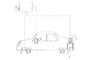
本発明の実施の形態の一例を図1「本発明の装置構成の一例を示す図」を参照して説明する。図1において、1は燃料タンク等の燃料容器であり、その天井に液面検出器2(センサ付き)が取り付けられている。センサとは、検出器で主に発信と受信の機能を行なう部品をいう。液面検出器2を取り付ける天井は、通常は容器の直胴部に対し直角であるが、車両空間上の制約や容器の強度を補強するため、天井の一部を平面以外の形状にすることも行われる。これとは別に車両の走行距離計3が取り付けられている。両者からの信号は演算装置4に送られ、ここで燃料の保有量、変化量および燃費(走行距離÷燃料消費量)が計算される。燃費の表示単位は(km/Liter)である。計算結果は運転者の近傍に取り付けられた表示装置5に表示される。
【0016】
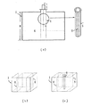
本発明で最も重要なのは液面検出器2である。液面検出器2は時々刻々の残存燃料の液面を正確に検出し、その変化量から燃料消費量を正確に把握できることが必要である。そのため本発明では、燃料液面を測定しようとする燃料容器の天井に液面検出器2のセンサを取り付ける。この液面検出器2は図2に示すように「容量重心点G」を通り、燃料容器の直胴部に平行な直線A−A′上の燃料液面を検出するように取り付ける。「容量重心点G」とは、容器内の液体容積を測定する場合の代表的な高さを示す位置をいい、例えば容器が長方形の箱型である場合は、その前後および左右の中心点に相当する位置をいう。この位置における燃料液面の高さhは、万一燃料容器が前後左右に角度θ1、θ2だけ傾斜しても、燃料容器内の燃料容積が一定ならば、常にその高さが変わらず同一の位置にあるという特色を持つ。
【0017】
今、図3(a)、(b)に示すような底面積S、高さHの直方体からなる箱型の燃料容器1について考えてみる。燃料容器1が水平に置かれている時(図3(a)の場合)、天井からの距離hに燃料液面がある時は、燃料体積Vは
V=S×(H−h)・・・・(2)
で表される。ここでSとHは燃料容器に固有な一定の値である。従ってVが一定であれば、hも一定であることが判る。燃料容器がどう傾いても、hは一定である。燃料容量が変化した場合も液面中心点G(容量重心点)の軌跡は、図2において常に直線A−A′上を移動する。従って容器の天井の中心点Aから燃料液面の中心点Gまでの距離hを正確に測定すれば、残存燃料の保有量を正確に測定することができる。
【0018】
また図3(a)、(b)において燃料を消費して燃料液面MがM 1 からM 2 に下降して容量重心点GがG 1 からG 2 に変化した時、天井からの距離hがh1からh2に変化したとすれば、燃料消費量Fは
F=V1−V2=S×(h2−h1) ………… (3)
で示される。(3)式の関係は、燃料容器が傾斜した場合でも、変わらない(図3(b)の場合)。更に燃料を補給した場合、燃料の補給前後における燃料液面までの距離hを各々測定して、(3)式に代入してやれば燃料の補給量を知ることができる。
【0019】
図3(a)、(b)では燃料容器が直方体の場合について説明したが、本発明が適用できるのは直方体の容器に限定されるものではない。例えば図3(c)に示すような断面を有する燃料容器であっても、燃料容器が一定の直胴部Lを持つ容器であって、燃料液面が直胴部Lの範囲を移動するものであれば、燃料容器の底部や上部は平坦でなくてもよいし、凹凸の有るものでもよい。また直胴部Lの断面は正方形、長方形、円形等断面積が一定であればよい。従って燃料容器が車両空間上の制約で異形にせざるをえない場合や補強のため容器を異形にする場合でも、直胴部が有る限り利用可能で、殆どの燃料容器に適用できる。
【0020】
本発明は液面の検出器のセンサを、容器の「容量重心点」の液面位置を測定できるよう正確に取り付け、この位置で測定した液面の高さから液の保有量を求めるものである。測定する位置が前記の重心点からはずれると容器が傾斜した場合正しい保有量を測定することができない。従って従来のような「浮き」を使うタイプは、その測定精度が不十分であるばかりでなく、図2の直線A−A′上を正確に移動させることが難しいので、本発明には適用し難い。出来れば小型の光学式や超音波式のセンサを選択して、非接触方式で測定することが望ましい。
【0021】
例えばこのような液面検出用のセンサに関しては、昨今のフォト・エレクトロニクスや超音波の利用技術の著しい発展の伴い、新たな技術革新が行われている。例えば株式会社キーエンスの1999、2000年版の商品カタログによれば、半導体レーザや超音波を使った小型で高性能の液面検出用のセンサが、数多く掲載されている。また1999年1月18日付けの日本経済新聞によれば、オムロン株式会社が、発光素子と受光素子を一体化して2mm×4mm×3mmの大きさの光センサの開発に成功し、形状認識や距離計測に高精度で対応できることを発表している。これらのセンサは測定波の発信部と受信部をコンパクトに一体化したものである。
【0022】
車両用の燃料容器に光学式や超音波式のセンサを使用する場合には、入射波および反射波の軸を図2の直線A−A′上に配置すれば測定上問題はない。入射波および反射波の位相差や時間差等から、容器天井の中心Aから液面Gまでの距離hを非接触方式で正確に測定することができる。
【0023】
また液面の位置を正確に測定する方法として、本発明者等が先に提案(特願平10−378174)したように、液面に少なくとも3本以上の光線を照射し、このうち1本は容器の一部に設定した水平基準線に対し垂直な基準線、他の2本以上の光線は前記基準線に対して対称でかつ所定の角度(α)を有する傾斜光線であり、これら3本以上の光線の反射角を受光し、前記基準光線による液面上の反射点から傾斜光線による各反射点までの長さ(d2,d2,d3,・・・)を測定する液面検知方法を用いても良い。この方法による場合には、反射光を受光する受光部を移動させる必要はなく、液面が振動で波打つ場合でも液面を正確に測定できる利点を有する。
【0024】
例えば、車両が出庫してから所定区間走行した後、入庫した場合に燃料液面の高さ(H−h)から、燃料の保有量を知るには、センサから得られる電気信号を図4に示すような論理図に基づいて計算する。まず、燃料保有量は、容器の形状から天井からの高さhと容量重心点を通る水平断面が囲む容量との関係式を予め演算装置に入力しておき、ここへ出庫時と入庫時に実測した高さhを代入してやれば容易に求めることができる。また燃料液面の高さ(H−h)を測定した時点の走行距離や測定時刺も同時に演算装置に記憶するようにしておけば、これらのデータを基に、任意の走行状態における燃費情報を得ることが可能となる。例えば燃料を途中で補給した場合には、補給前後の液面の変化から演算器に補給量を記憶させ、ある一定走行距離をその走行区間内で実際に消費した燃料量で割ることにより当該区間の燃費を得ることができる。
【0025】
液面の高さを入力するタイミングは、業務用車両の場合は一般的には車庫からの出庫時、入庫時とするケースが多いが、必要に応じ輸送の中継時、客先での到着時、高速道の休憩時、または給油時等自由に選択することができる。さらに場合によっては、交差点における待機時等、測定頻度を短縮することも可能である。
【0026】
本発明で使用する走行距離計としては、一般の車両で通常使用されている車軸の回転数から計測する方式のものが利用できる。車軸の回転数を電気信号に変換し、演算装置と組み合わせて走行距離として扱えるように変換すればよい。
【0027】
本発明では燃料容器内の液面の高さのデータから前記、演算装置を用いて燃費を算出する。従って液面が大きく変動していると、正確な燃費の算出が困難となる。昨今の演算装置は、データに変動がある場合は複数の入力データを取り入れ、これを平均化する演算機構を備えているが、入力データにはバラツキが少ない方が望ましい。例えば、市販の車両の300リットル型燃料容器には、通常容器内に図5(b)に示すように車両の進行方向に対し直角の位置に縦の緩衝板8を複数の枚数取り付け、燃料の波動を押さえる工夫が施されている。従来の浮きを使用した燃料計では、この種の緩衝板であれば十分である。本発明のように高感度のセンサを使用した場合でも、車両が停止した後、データの入力までに十分な時間が取れる場合には従来方式の緩衝板で問題はない。
【0028】
しかし、例えば交差点におけるデータの入力時のように時間が十分取れない場合には、燃料容器内に液面波動を防止する装置を取り付けることが望ましい。一般的には車両が停止した際の燃料液面の波動は、燃料容器の容量が大きくなればなる程、波動の静止までに時間を要する。このため本発明の場合は、センサで測定する対象の面積を極力、小さく限定することが最も有効である。図5には、測定面積を小さくするために使用した波動防止対策の一例を示す。図5(a)の例では測定部に円筒型の緩衝筒6のみを取り付けた場合を示すが、測定対象の面積を小さくするものであれば、形状は角筒型でも多角型でも良く、更に緩衝筒6を二重等に取り付けることにより波動防止効果を更に高めることができる。緩衝筒6には小孔7またはスリットを多数設け、筒の内外の液面が一定になり易いようにする。緩衝筒6の長さは容器の直胴部とほぼ同じ長さにすればよい。緩衝筒の太さは、測定ビームが緩衝筒から干渉を受けない太さで普通は直径60〜100mm程度あれば良いが、燃料容器1の大きさや液面検出器2の性能等により可変である。また図5(c)のように緩衝板8と緩衝筒6を併用することは、何等支障はない。
【0029】
本発明で使用する演算装置としては、公知のマイクロコンピュータが利用できる。必要な機能としては先ず計測時点で液面検出装置2からの信号を液面深さに換算して燃料保有量を算出する機能、車軸の回転数からの信号から走行距離を算出する機能が挙げられる。次に、これらのデータから燃費を算出する機能が必要である。更に、これらのデータや演算結果を記録するための記憶装置が必要である。記憶されたデータから走行距離当たりの燃費を求めたり、一日当たりの燃費を求めたり、月間の平均燃費を求める等必要なデータを算出するための演算機能を組み込めば応用範囲を広めることができる。
【0030】
本発明は、燃料保有量の変化量と走行距離から燃費(走行距離÷燃料消費量)を計算し、これを表示する表示部を備えている物である。表示部は単に燃費を表示する以外に、任意の時間帯の燃料の正確な保有量や任意の走行区間の燃料消費量や補給量を表示することも可能である。表示部の方式は特に制限はない。例えば運転席の見易い部位に、デジタル式の表示部を設置することにより、運転者が時々刻々の燃費や正確な燃料保有量、消費量や補給量等を知ることが可能になり、経済的でしかも環境保全に寄与する優しい運転をすることが可能になる。更に本データを車両から取り出してホストコンピュータに転記し、継続的な燃料管理に利用することができる。例えば業務上、運行管理者の立場にある者の場合は、日々の運行当たりの燃費を各運転手毎に継続的に管理し、正確で公平なデータを基に最も経済的な運転を目指して、運転手への個別指導を行うことが可能である。
【0031】
【作用】
本発明は、容器の傾きの有無に拘らず、容量重心点では常に液面が一定位置にあることを利用して、容器内の燃料保有量を正確に測定するようにして、その結果に基づき燃費を算出しデジタル表示することにした。
【0032】
【実施例】
(測定時間を決めるための実験)
本実施例では、直方体燃料容器の液面測定部分に、緩衝板8のみを設け緩衝筒を取り付けない場合と、図6(b)に示すように緩衝板8と図6(c)の緩衝筒6を併用した緩衝機構を設けた場合とについて計測した。測定に先立ち燃料液面の波動の影響を調べるため車両が停止した時間経過と液面測定値の関係を調べた。燃料容器は実用化されている燃料タンクと同じ寸法と容量を持つ鋼板製の角型容器(幅600mm、長さ1030mm、高さ500mm、図6(a)を参照)を使用した。燃料容器上面の長方形の対角線交点に超音波センサ2を超音波の発信軸が容器上面に垂直となるように正確に取り付けた。燃料容器内には軽油(密度0.835g/cm3、動粘度3.47CSt)を所定量充填した。図7には、測定に用いたシステムの構成を示す。センサ2からのアナログ信号はPCカード型データ収集システム9に送り、ここからノート型パソコン10に取り込んでデータの波形収集、解析を行った。使用したセンサおよびデータ収集システム9の主な仕様は表1および表2の通りである。
【0033】
【表1】

【表2】
測定結果を表−3に示す。表中、右欄は前記緩衝板8と緩衝筒6を併用した緩衝装置を取り付けた場合、左欄は緩衝筒6の緩衝装置を取り付けなかった場合の結果を示す(図5 参照)。容器は、実際の車両の走行と停止を想定して、各測定時に同一の振動を与えた。表3中の液面までの高さ(mm)は、各測定時において2回/秒の間隔で5秒間に10回測定し、その平均値で示した。また、この測定時の経過時間に対する液面波動の減衰曲線を図8に示す。図中8(a)は、緩衝筒のない場合、8(b)は緩衝筒を併用した場合である。これらの結果から、緩衝筒を併用した場合には、車両が停止した後20秒を経過すれば液面の波動はおさまり、実用上支障のない液面測定ができることが判り、緩衝筒の効果が確認された。また緩衝筒を使用しない場合は、40秒経過後に測定すれば良いことが判明した。
【0036】
【表3】
(実施例1)
前記実験例と同一の燃料容器および同一の計測システムを搭載した車両を使用して、前記実験例と同一の測定方法を使用して、実際の一走行当たりの燃費を計測した例を示す。液面の測定をするまでには車両停止後30秒以上が経過していた。燃費の計算に当たっては、燃料タンクの液面の変位差から「燃料の消費量」を求め、車両の走行指示計の距離差から「走行距離」を求めた。燃費は、燃費=(走行距離)/(燃料消費量)で計算した。単位はkm/Literである。測定結果を表4に示す。表中、A欄は本発明に基づいて測定した結果である。またB欄は、確認のため燃料容器の側面に連通管式のスケールを取り付け、車両を水平に停車させたのを確認して、スケールの読取り値から計算で燃料消費量を求め、燃費を算出した値である。C欄には比較のために既存の車両に取り付けられているフロート式燃料計の読みを示す。表4から判る通り、本発明によれば、何ら計測の手段を煩わすことなしに、任意の走行区間に対して正確な燃費を知ることが可能である。一方、既存の燃料計から燃費を求めることは不可能であった。
【0038】
【表4】
【0039】
(実施例2)
実施例1と同様な車両を使用して、途中ガソリンスタンドで給油した場合の一走行当たりの燃費を計測した例を示す。給油前の液面の測定は、ガソリンスタンドに入り車両を所定位置に停車し、30秒後に行った。給油後の液面の測定は、給油を開始し所定量充填した後、30秒後に行った。液面までの高さの測定は、実施例1と同様10回の平均値で示す。燃費の計算は、前述の方法と同じ計算法で求めたが途中で燃料の補給を行ったので、燃料の消費量については、補給量分を補正した。測定結果を表5に示す。表中、A欄は本発明に基づいて測定した結果である。またB欄は、比較のため車両に取り付けられている既存のフロート式燃料計の読みを示す。表5から判る通り、本発明によれば、途中ガソリンスタンドで燃料を補給した場合でも、何ら計測の手を煩わすことなしに任意の走行区間に対して正確な燃費を知ることが可能である。一方、既存の燃料計から燃費を求めることは不可能であった。
【表5】
【発明の効果】
本発明の効果は、従来、運転管理の面で最も重要な項目であった「燃料保有量と変化量の正確な把握」と「燃費の実績」が運転席から監視可能となる。これは従来の燃料計からでは、全く不可能なことであった。本発明によれば燃費の監視が、単にトラックやバス業界等における燃料費の節約という経済効果の追及に加え、地球環境の保全に向けて一般消費者の意識向上にも貢献すると思われる。また「燃費の実績値」がメ−カ−のカタログ表での記載から、実際に走っている車両から得ることが可能となり、将来の燃費の改善に向けて使用者側からの『生きたデータ』が入手でき、環境保全の指導者やメ−カ−側にとっても貴重な情報を得ることができる。
【図面の簡単な説明】
【図1】本発明の装置構成の一例を示す図である。
【図2】「容量重心点」を説明する図である。
【図3】容器中の液面位置の測定原理を説明する図である。
【図4】燃費を求める論理図である。
【図5】波動防止装置を示す説明図である。
【図6】実施例における燃料タンクの構造を示す説明図である。
【図7】実施例における機器の配置と構成を示す説明図である。
【図8】実施例における液面の波動の減衰曲線を示す説明図である。
【図9】従来使われている液面計の説明図である。
【図10】従来、使われている車両の燃料タンクの液面計の一例を示す説明図である。
【符号の説明】
1 燃料容器
2 液面検出器
3 走行距離計
4 演算装置
5 表示装置
6 液面波動防止用の緩衝筒
7 同 緩衝筒表面の小孔
8 液面波動防止用の緩衝板
9 PCカード型デ−タ収集機
10 ノ−ト型パソコン
11 浮子[0001]
BACKGROUND OF THE INVENTION
The present invention relates to a fuel consumption detection means for a vehicle or the like, and more particularly to a fuel consumption detection display device that accurately measures fuel consumption during driving of an automobile and accurately calculates and displays the fuel consumption according to the travel distance.
[0002]
[Prior art]
In recent years, the technology related to saving fuel consumption of automobiles has made remarkable progress in recent years, as seen in the advent of hybrid vehicles that use batteries together with the power source in addition to the improvement of the conventional engine body. It has been. How to develop a vehicle with excellent fuel efficiency is an eternal issue for vehicle manufacturers. Furthermore, in recent years, the improvement in fuel efficiency is not only for the pursuit of the economic merit of fuel saving, but also for vehicle manufacturers as well as consumers from the viewpoint of preventing global warming due to the reduction of exhaust gas. It has become a subject of interest.
[0003]
Needless to say, fuel consumption is the number of miles traveled per unit fuel. In other words, fuel consumption is mileage ÷ fuel consumption (1)
It is represented by The fuel consumption changes depending on various factors such as the structure of the vehicle, the weight of the load, the road condition, the traveling speed of the vehicle, and the driving method. In order to achieve the purpose of transportation, fuel efficiency is largely dependent on the structure of the vehicle, and vehicle manufacturers are continuing to develop technologies with the aim of improving the structure of engines and other vehicles for the purpose of improving fuel efficiency.
[0004]
However, in view of today's situation, it seems that the driver of the vehicle pays sufficient attention to the driving method with the intention of improving fuel efficiency. This is because today's vehicles do not have a fuel consumption detection device that displays fuel consumption. Among the above formulas (1) for calculating the fuel consumption, a distance meter with a practically sufficient accuracy is provided for the “travel distance” of the numerator. However, with respect to the “fuel consumption” of the denominator, at present, only a fuel gauge indicating a rough fuel holding amount for the driver to determine whether or not fuel replenishment is necessary is equipped.
[0005]
For example, various types of fuel level gauges that have been generally put into practical use in the industry are used as shown in FIGS. 9A to 9C. The float method using Fig. 9A is exclusively employed. FIG. 9A shows a system in which a float is arranged on the liquid surface, and the vertical movement of the float is converted into an electric signal and taken out. FIG. 9B shows a differential pressure method using a pressure difference between the gas phase portion and the liquid phase portion. FIG. 9C shows a torque tube system using the buoyancy of a tube placed in an auxiliary container attached outside the container. Of these, the float-type liquid level gauge is lightweight and safe and can be used as a source of ignition or explosion even if it is used for combustible materials such as gasoline or light oil. Used to detect the amount of fuel held.
[0006]
However, when this type of detector is converted into an electrical signal and digitally displayed, it is limited to two significant digits at best in terms of accuracy. In addition, when the container is placed not only on a flat ground but also on an inclined ground like a vehicle, the level of the container and the liquid level of the fuel are inclined, and an error appears in the display of the fuel holding amount. For this reason, when driving in a state close to the lower limit of the amount of fuel held, the “fuel lower limit alarm” often turns on or flashes when approaching a slope. This is a phenomenon that occurs in the conventional method because the mounting position of the float, which is the detection unit of the float type liquid level gauge, is not specified and is independent. Therefore, when the container is tilted, it is necessary to detect the tilt of the liquid level in order to accurately know the volume of fuel in the container, and in order to accurately measure the tilt, the number of floats in the detector is increased. Must-have.
[0007]
In addition, in order to convert the floating position into an accurate liquid level display, a precise mechanical transmission mechanism is required. For this reason, the conventional float-type liquid level gauge cannot be used when it is necessary to display the amount of fuel held by three or more significant figures, or when calculating the fuel consumption from the difference in the amount held. Currently, it is used as a “standard gauge” to indicate the approximate amount of fuel held. FIG. 10 shows an example of a float type liquid level gauge of a fuel container that is currently generally used for large trucks.
[0008]
Regarding the indication of the remaining amount of fuel, most vehicles on the market are generally equipped with an indicator that shows the amount of analog holding and a lower limit alarm for the capacity. There are almost no examples that can be equipped with an indicator that shows the amount of change in fuel and fuel that can be produced.
[0009]
Therefore, with regard to the display of fuel consumption that requires accuracy, all automakers add measurement conditions to the “catalog” and present numerical values from experimental vehicles equipped with measuring instruments that specifically measure fuel consumption. However, there are almost no examples of attaching a fuel consumption display device to a commercially available vehicle.
[0010]
On the other hand, there is a method of measuring the flow rate of fuel consumption as means for accurately grasping the fuel consumption amount and calculating the fuel consumption. This type of flow rate measuring device is installed to measure the fuel consumption of a vehicle manufacturer's prototype, and the fuel consumption in various driving modes is accurately measured using a test course or the like. However, in this method, a contact type flow meter must be attached to the fuel supply system, which can be said to be the lifeline of vehicle travel, and if the flow of fuel in this flow system is obstructed, the vehicle cannot travel. There is a risk of becoming. Therefore, although there is no problem in traveling on a test course or the like, for example, when assuming traveling of a general vehicle on a highway, careful protection measures against these abnormal assumptions are indispensable.
[0011]
[Problems to be solved by the invention]
The present invention has been made in view of the above problems, and by combining a non-contact type accurate liquid level detection device using light, sound waves, etc. with an existing odometer , an arbitrary time zone or arbitrary It is an object of the present invention to provide an apparatus capable of detecting an accurate amount of fuel held and consumed per driving section and knowing accurate information on fuel consumption from the driver's seat of the vehicle.
[0012]
[Means to solve the problem]
In the present invention, the means for detecting the amount of fuel held in the fuel container and the means for detecting the mileage of the vehicle are used to convert the fuel consumption amount and the mileage obtained from the amount of change in the fuel holding amount into an electrical signal. An arithmetic unit for taking out and calculating the fuel consumption from these electric signals and means for displaying the calculated fuel consumption were prepared.
[0013]
In addition, as a means of accurately detecting the amount of fuel held in the fuel container, it is perpendicular to the cross section perpendicular to the straight body of the fuel container and is the center point for measuring the capacity of the fuel container (hereinafter referred to as the “capacity center of gravity”). The method of detecting the fuel liquid level position on the line passing through the non-contact method was adopted. The straight body portion of the fuel container here refers to the body portion of the fuel container that is positioned perpendicular to the liquid level in the fuel container when the fuel container is placed horizontally. This method makes it possible to accurately detect the amount of fuel held in the fuel container even when the container is tilted and shakes, and the fuel supply path does not require any modification. it is possible to measure the consumption and that Do not.
[0014]
Further, the present invention includes a calculation device for converting the fuel consumption amount and the mileage obtained from the change amount of the fuel holding amount into an electrical signal, taking out the electrical signal, calculating fuel consumption from the electrical signal, and a display device for displaying the calculation result. It was. Details of the present invention will be described below.
[0015]
DETAILED DESCRIPTION OF THE INVENTION
An example of an embodiment of the present invention will be described with reference to FIG. 1 “a diagram showing an example of an apparatus configuration of the present invention”. In Figure 1, 1 is a fuel container such as a fuel tank, the liquid level detector 2 (with sensor) is installed in the ceiling. A sensor refers to a component that mainly performs transmission and reception functions with a detector. The ceiling to which the
[0016]
The most important in the present invention is the
[0017]
Now, FIG. 3 (a), that consider the bottom surface area S, the fuel container 1 a box type made of cuboid height H as shown in (b). When
V = S × (H−h) (2)
It is represented by Here, S and H are constant values inherent to the fuel container. Therefore, it can be seen that if V is constant, h is also constant. No matter how the fuel container is tilted, h is constant. Even when the fuel capacity changes, the locus of the liquid surface center point G (volume center of gravity point) always moves on the straight line A-A 'in FIG. Therefore, if the distance h from the center point A of the container ceiling to the center point G of the fuel liquid level is accurately measured, the amount of remaining fuel can be accurately measured.
[0018]
Also FIG. 3 (a), when consuming the fuel fuel level M capacitive center of gravity G descends from M 1 to M 2 is changed from G 1 to G 2 (b), the distance from the ceiling If h changes from h 1 to h 2 , the fuel consumption F is
F = V 1 −V 2 = S × (h 2 −h 1 ) (3)
Indicated by (3) the relationship, even if the fuel container was inclined, unchanged (in the case of Figure 3 (b)). Further when refueling, the distance h to the fuel level of definitive before and after refueling each measured, it is possible to know the amount of supply fuel do it by substituting the equation (3).
[0019]
Although FIGS. 3A and 3B have described the case where the fuel container is a rectangular parallelepiped, the present invention is not limited to a rectangular parallelepiped container. For example, even if the fuel container has a cross section as shown in FIG. 3 (c), the fuel container is a container having a certain straight body L, and the fuel liquid level moves within the range of the straight body L. If so, the bottom and top of the fuel container may not be flat or may be uneven. The cross section of the straight body L may be constant, such as a square, a rectangle, or a circle. Therefore, even when the fuel container must be deformed due to restrictions on the vehicle space or when the container is deformed for reinforcement, the fuel container can be used as long as it has a straight body portion and can be applied to most fuel containers.
[0020]
In the present invention, the sensor of the liquid level detector is accurately attached so that the liquid level position of the “volume center of gravity” of the container can be measured, and the amount of liquid held is obtained from the height of the liquid level measured at this position. is there. If the measurement position deviates from the center of gravity, the correct holding amount cannot be measured when the container is tilted. Therefore, the conventional type using “floating” is not only insufficient in measurement accuracy but also difficult to accurately move on the straight line AA ′ in FIG. hard. If possible, it is desirable to select a small optical or ultrasonic sensor and perform measurement in a non-contact manner.
[0021]
For example, with respect to such a sensor for detecting a liquid level, new technological innovations have been made along with recent remarkable developments in photoelectronics and ultrasonic wave utilization technologies. For example, according to the product catalog of 1999, 2000 edition of Keyence Corporation, there are many small and high performance liquid level detection sensors using semiconductor lasers and ultrasonic waves. According to the Nihon Keizai Shimbun dated January 18, 1999, OMRON Corporation succeeded in developing an optical sensor with a size of 2 mm x 4 mm x 3 mm by integrating a light emitting element and a light receiving element. Announces that it can handle distance measurement with high accuracy. These sensors are a compactly integrated transmitter and receiver for measurement waves.
[0022]
When an optical or ultrasonic sensor is used for a fuel container for a vehicle, there is no problem in measurement if the axes of the incident wave and the reflected wave are arranged on the straight line A-A 'in FIG . The distance h from the center A of the container ceiling to the liquid level G can be accurately measured in a non-contact manner from the phase difference or time difference between the incident wave and the reflected wave.
[0023]
Further, as a method for accurately measuring the position of the liquid level, as proposed previously by the present inventors (Japanese Patent Application No. 10-378174) , at least three or more rays are irradiated on the liquid level, and one of these is irradiated. Is a reference line perpendicular to a horizontal reference line set in a part of the container, and the other two or more light rays are inclined light rays that are symmetrical with respect to the reference line and have a predetermined angle (α). Liquid that receives reflection angles of more than one light beam and measures the length (d 2 , d 2 , d 3 ,...) From the reflection point on the liquid surface by the reference light beam to each reflection point by the inclined light beam. A surface detection method may be used. In the case of this method, there is no need to move the light receiving portion that receives the reflected light, and there is an advantage that the liquid level can be accurately measured even when the liquid level is undulated by vibration.
[0024]
For example, in order to know the amount of fuel held from the height (Hh) of the fuel level when the vehicle has entered after traveling for a predetermined section after leaving the vehicle, the electrical signal obtained from the sensor is shown in FIG. Calculate based on the logic diagram shown. First, the amount of fuel held is measured in advance when entering the warehouse and entering the relational expression between the height h from the ceiling based on the shape of the container and the volume enclosed by the horizontal cross section passing through the center of gravity of the capacity. This can be easily obtained by substituting the height h. If the travel distance at the time of measuring the fuel liquid level (Hh) and the measurement time card are also stored in the arithmetic unit at the same time, the fuel consumption information in an arbitrary travel state can be based on these data. Can be obtained. For example, when fuel is replenished midway, the replenishment amount is stored in the calculator from the change in the liquid level before and after replenishment, and a certain travel distance is divided by the amount of fuel actually consumed within that travel segment. The fuel economy can be obtained.
[0025]
The timing for entering the liquid level is generally used for commercial vehicles when leaving the garage or when entering the warehousing. It can be selected freely during breaks on the expressway or during refueling. Furthermore, depending on the case, it is possible to shorten the measurement frequency, such as when waiting at an intersection.
[0026]
As the odometer used in the present invention, a method of measuring from the number of rotations of an axle normally used in a general vehicle can be used. What is necessary is just to convert the rotation speed of an axle shaft into an electric signal so that it can be treated as a travel distance in combination with an arithmetic device.
[0027]
In the present invention, the fuel consumption is calculated from the liquid level data in the fuel container using the arithmetic unit. Therefore, if the liquid level fluctuates greatly, it becomes difficult to accurately calculate the fuel consumption. A recent computing device includes a computing mechanism that takes in a plurality of input data and averages the data when there is a change in the data, but it is desirable that the input data has less variation. For example, in a commercially available vehicle 300 liter type fuel container, as shown in FIG. 5 (b), a plurality of
[0028]
However, if sufficient time is not available, for example, when data is input at an intersection, it is desirable to install a device that prevents liquid surface waves in the fuel container. In general, the wave of the fuel liquid level when the vehicle is stopped requires more time for the wave to stop as the capacity of the fuel container increases. Therefore, in the case of the present invention, it is most effective to limit the area of the object measured by the sensor as small as possible. FIG. 5 shows an example of a wave prevention measure used to reduce the measurement area. 5A shows a case where only the
[0029]
A known microcomputer can be used as the arithmetic device used in the present invention. The necessary functions include a function of calculating a fuel holding amount by converting a signal from the liquid
[0030]
The present invention includes a display unit that calculates fuel consumption (travel distance / fuel consumption) from the amount of change in fuel holding amount and travel distance, and displays this. In addition to simply displaying fuel consumption, the display unit can also display the exact amount of fuel held in any time zone, the amount of fuel consumed and the amount of replenishment in any travel section. The method of the display unit is not particularly limited. For example, by installing a digital display at an easy-to-see part of the driver's seat, it is possible for the driver to know the fuel consumption, accurate fuel holding amount, consumption amount, replenishment amount, etc. In addition, gentle driving that contributes to environmental conservation becomes possible. Furthermore, this data can be taken out of the vehicle and transferred to the host computer for use in continuous fuel management. For example, in the case of a person who is in the position of an operation manager for business, the fuel consumption per daily operation is continuously managed for each driver, aiming for the most economical driving based on accurate and fair data. It is possible to give individual guidance to the driver.
[0031]
[Action]
The present invention makes use of the fact that the liquid level is always at a constant position at the center of gravity of the volume regardless of whether the container is tilted, and based on the result, the fuel holding amount in the container is accurately measured. The fuel consumption was calculated and digitally displayed.
[0032]
【Example】
(Experiment to determine measurement time)
In the present embodiment, only the
[0033]
[Table 1]
[Table 2]
The measurement results are shown in Table-3. In the table, the right column shows the result when the shock absorber using the
[0036]
[Table 3]
Example 1
An example in which the actual fuel consumption per one run is measured using a vehicle equipped with the same fuel container and the same measurement system as in the experimental example and using the same measurement method as in the experimental example. It took 30 seconds or more after the vehicle stopped before the liquid level was measured. In calculating the fuel consumption, the “fuel consumption” was determined from the difference in the liquid level of the fuel tank, and the “travel distance” was determined from the distance difference between the travel indicators of the vehicle. The fuel consumption was calculated by fuel consumption = (travel distance) / (fuel consumption). The unit is km / liter. Table 4 shows the measurement results. In the table, column A is the result of measurement based on the present invention. In column B, a communication pipe scale is attached to the side of the fuel container for confirmation, and it is confirmed that the vehicle is stopped horizontally. The fuel consumption is calculated from the scale reading, and the fuel consumption is calculated. It is the value. Column C shows the reading of a float fuel gauge attached to an existing vehicle for comparison. As can be seen from Table 4, according to the present invention, it is possible to know the exact fuel consumption for any traveling section without bothering the means of measurement. On the other hand, it was impossible to obtain fuel consumption from existing fuel gauges.
[0038]
[Table 4]
[0039]
(Example 2)
The example which measured the fuel consumption per driving | running | working at the time of using a vehicle similar to Example 1 and refueling in a gasoline station on the way is shown. The liquid level before refueling was measured 30 seconds after entering the gas station and stopping the vehicle at a predetermined position. The liquid level after refueling was measured 30 seconds after refueling was started and a predetermined amount was filled. The measurement of the height to the liquid level is shown as an average value of 10 times as in Example 1. The fuel consumption was calculated by the same calculation method as described above, but the fuel was replenished midway, so the fuel consumption was corrected for the replenishment amount. Table 5 shows the measurement results. In the table, column A is the result of measurement based on the present invention. In addition, column B shows the reading of an existing float fuel gauge attached to the vehicle for comparison. As can be seen from Table 5, according to the present invention, even when fuel is replenished at a gas station on the way, it is possible to know the exact fuel consumption for an arbitrary traveling section without bothering the measurement. On the other hand, it was impossible to obtain fuel consumption from existing fuel gauges.
[Table 5]
【The invention's effect】
As an effect of the present invention, “accurate grasp of fuel holding amount and change amount” and “actual performance of fuel consumption”, which have been the most important items in terms of operation management, can be monitored from the driver's seat. This was completely impossible with conventional fuel gauges. According to the present invention, it is considered that monitoring of fuel consumption contributes not only to pursuing the economic effect of saving fuel costs in the truck and bus industries, but also to raising the awareness of general consumers for the preservation of the global environment. In addition, "the actual value of the fuel consumption" turtles - mosquitoes - of from the description in the catalog tables, actually in which it is possible to obtain from the vehicle that ran, "live data from the user side to the improvement of future fuel consumption "it is available, the leaders quit environmental conservation - mosquitoes - it is possible to obtain a very valuable information on the side.
[Brief description of the drawings]
FIG. 1 is a diagram showing an example of a device configuration of the present invention.
FIG. 2 is a diagram illustrating a “capacity center of gravity”.
FIG. 3 is a diagram for explaining a principle of measuring a liquid surface position in a container.
FIG. 4 is a logical diagram for obtaining fuel consumption.
FIG. 5 is an explanatory view showing a wave preventing device.
FIG. 6 is an explanatory view showing a structure of a fuel tank in an example.
FIG. 7 is an explanatory diagram showing the arrangement and configuration of devices in an embodiment.
FIG. 8 is an explanatory diagram showing an attenuation curve of a wave of liquid level in an example.
FIG. 9 is an explanatory diagram of a conventional level gauge.
FIG. 10 is an explanatory view showing an example of a level gauge of a fuel tank of a vehicle that has been used conventionally.
[Explanation of symbols]
DESCRIPTION OF
Claims (6)
Priority Applications (1)
| Application Number | Priority Date | Filing Date | Title |
|---|---|---|---|
| JP22031199A JP4415401B2 (en) | 1999-02-01 | 1999-06-30 | Fuel consumption detector |
Applications Claiming Priority (3)
| Application Number | Priority Date | Filing Date | Title |
|---|---|---|---|
| JP11-59105 | 1999-02-01 | ||
| JP5910599 | 1999-02-01 | ||
| JP22031199A JP4415401B2 (en) | 1999-02-01 | 1999-06-30 | Fuel consumption detector |
Publications (3)
| Publication Number | Publication Date |
|---|---|
| JP2000292240A JP2000292240A (en) | 2000-10-20 |
| JP2000292240A5 JP2000292240A5 (en) | 2006-04-20 |
| JP4415401B2 true JP4415401B2 (en) | 2010-02-17 |
Family
ID=26400143
Family Applications (1)
| Application Number | Title | Priority Date | Filing Date |
|---|---|---|---|
| JP22031199A Expired - Fee Related JP4415401B2 (en) | 1999-02-01 | 1999-06-30 | Fuel consumption detector |
Country Status (1)
| Country | Link |
|---|---|
| JP (1) | JP4415401B2 (en) |
Families Citing this family (6)
| Publication number | Priority date | Publication date | Assignee | Title |
|---|---|---|---|---|
| KR100511206B1 (en) * | 2001-12-24 | 2005-08-31 | 한국과학기술원 | Apparatus for two-phase mixture level measurment using ultrasonic |
| DE102008027969B4 (en) * | 2008-06-12 | 2017-11-02 | Hella Kgaa Hueck & Co. | Device for detecting a level with a damping cup |
| JP6167979B2 (en) * | 2014-04-10 | 2017-07-26 | 株式会社デンソー | Fuel consumption calculation device for vehicles |
| GB201705039D0 (en) | 2017-03-29 | 2017-05-10 | Weston Aerospace Ltd | A Liquid level monitoring system |
| CN113155220A (en) * | 2021-04-23 | 2021-07-23 | 广东电网有限责任公司梅州供电局 | Remote oil consumption monitoring system and method |
| CN113483850B (en) * | 2021-06-28 | 2023-02-07 | 东风华神汽车有限公司 | Method, device and equipment for calculating remaining oil endurance mileage and storage medium |
-
1999
- 1999-06-30 JP JP22031199A patent/JP4415401B2/en not_active Expired - Fee Related
Also Published As
| Publication number | Publication date |
|---|---|
| JP2000292240A (en) | 2000-10-20 |
Similar Documents
| Publication | Publication Date | Title |
|---|---|---|
| CA2969954C (en) | System and method for determining volume of fluid in a tank | |
| US11887052B2 (en) | System and method for determining volume of fluid in a tank | |
| US8150613B2 (en) | Technique for detecting shifted cargo | |
| US5072615A (en) | Apparatus and method for gauging the amount of fuel in a vehicle fuel tank subject to tilt | |
| KR101397671B1 (en) | Freight transport safety system | |
| CN1749989A (en) | Method and system and programme foe vehicle fuel fee information management | |
| JP4415401B2 (en) | Fuel consumption detector | |
| JP2007240167A (en) | Vehicle-mounted travel distance measuring apparatus | |
| JPH10193992A (en) | Detecting method and device for fuel residual quantity in fuel tank | |
| KR20190049176A (en) | Measuring Apparatus for Vehicle Load Weight | |
| JPH0719939A (en) | Navigation device with self-weight meter function | |
| CN105737933A (en) | Mining dump truck oil level measurement device and measurement method | |
| KR101308925B1 (en) | Real time weight measuring device and method for vehicle | |
| US5121097A (en) | System for preventing fraud in the use of a taximeter | |
| JP2000292240A5 (en) | ||
| CA2991604A1 (en) | System and method for determining volume of fluid in a tank | |
| JP4251328B2 (en) | Tank truck weighing device and weighing method | |
| CN108303159B (en) | Simple method for detecting current oil quantity of oil tank | |
| US4676102A (en) | Device for indicating the quantity of a liquid in a reservoir and reservoir provded with such a device | |
| Maarof et al. | Development of an after-market universal fuel gauge for motorcycle | |
| CA3159040A1 (en) | Non-invasive fluid volume measurement device, method, and system for determining fluid volume within a movable pond | |
| CN106969809A (en) | A kind of vehicle-mounted LNG bottles of liquid-level detecting methods and device | |
| CA2990099A1 (en) | System and method for identifying a fuel loss | |
| CN211696541U (en) | Oil consumption measuring system for diesel power forklift | |
| EP3098577A1 (en) | Fuel level detection system and method |
Legal Events
| Date | Code | Title | Description |
|---|---|---|---|
| A521 | Request for written amendment filed |
Free format text: JAPANESE INTERMEDIATE CODE: A523 Effective date: 20060127 |
|
| A621 | Written request for application examination |
Free format text: JAPANESE INTERMEDIATE CODE: A621 Effective date: 20060127 |
|
| A977 | Report on retrieval |
Free format text: JAPANESE INTERMEDIATE CODE: A971007 Effective date: 20080519 |
|
| A131 | Notification of reasons for refusal |
Free format text: JAPANESE INTERMEDIATE CODE: A131 Effective date: 20080715 |
|
| A521 | Request for written amendment filed |
Free format text: JAPANESE INTERMEDIATE CODE: A523 Effective date: 20080901 |
|
| A131 | Notification of reasons for refusal |
Free format text: JAPANESE INTERMEDIATE CODE: A131 Effective date: 20081209 |
|
| A521 | Request for written amendment filed |
Free format text: JAPANESE INTERMEDIATE CODE: A523 Effective date: 20090204 |
|
| TRDD | Decision of grant or rejection written | ||
| A01 | Written decision to grant a patent or to grant a registration (utility model) |
Free format text: JAPANESE INTERMEDIATE CODE: A01 Effective date: 20091110 |
|
| A01 | Written decision to grant a patent or to grant a registration (utility model) |
Free format text: JAPANESE INTERMEDIATE CODE: A01 |
|
| A61 | First payment of annual fees (during grant procedure) |
Free format text: JAPANESE INTERMEDIATE CODE: A61 Effective date: 20091116 |
|
| R150 | Certificate of patent or registration of utility model |
Free format text: JAPANESE INTERMEDIATE CODE: R150 |
|
| FPAY | Renewal fee payment (event date is renewal date of database) |
Free format text: PAYMENT UNTIL: 20121204 Year of fee payment: 3 |
|
| FPAY | Renewal fee payment (event date is renewal date of database) |
Free format text: PAYMENT UNTIL: 20121204 Year of fee payment: 3 |
|
| FPAY | Renewal fee payment (event date is renewal date of database) |
Free format text: PAYMENT UNTIL: 20151204 Year of fee payment: 6 |
|
| R250 | Receipt of annual fees |
Free format text: JAPANESE INTERMEDIATE CODE: R250 |
|
| R250 | Receipt of annual fees |
Free format text: JAPANESE INTERMEDIATE CODE: R250 |
|
| LAPS | Cancellation because of no payment of annual fees |