JP4412809B2 - Instruction device for electronic component mounting equipment - Google Patents
Instruction device for electronic component mounting equipment Download PDFInfo
- Publication number
- JP4412809B2 JP4412809B2 JP2000141950A JP2000141950A JP4412809B2 JP 4412809 B2 JP4412809 B2 JP 4412809B2 JP 2000141950 A JP2000141950 A JP 2000141950A JP 2000141950 A JP2000141950 A JP 2000141950A JP 4412809 B2 JP4412809 B2 JP 4412809B2
- Authority
- JP
- Japan
- Prior art keywords
- electronic component
- feeder
- component feeder
- instruction
- visual
- Prior art date
- Legal status (The legal status is an assumption and is not a legal conclusion. Google has not performed a legal analysis and makes no representation as to the accuracy of the status listed.)
- Expired - Fee Related
Links
Images


Landscapes
- Supply And Installment Of Electrical Components (AREA)
Description
【0001】
【発明の属する技術分野】
電子部品実装装置において電子部品を供給する電子部品フィーダに関する情報に基づいて指示を出力する電子部品実装装置の指示装置に関する。
【0002】
【従来の技術】
一般に、電子部品実装装置では、電子部品を吸引した状態で保持する吸着ノズルを有し、当該吸着ノズルにより電子部品をプリント基板上の実装位置に搬送し、電子部品をプリント基板上に実装する。
【0003】
また、電子部品実装装置には、吸着ノズルの吸着位置に電子部品を一つずつ供給する電子部品フィーダが横一列に複数並んだ状態で装着されている。そして、上記電子部品装着装置には、複数の電子部品フィーダを横一列に並んだ状態に装着するためのフィーダバンクが設けられている。また、各電子部品フィーダは、該当する電子部品フィーダ自体を上記フィーダバンクに取り付けるための位置決め固定手段と、フィーダバンク上の各スロット毎に設けられた位置決めピン孔に挿入される位置決め用の基準ピンを備えている。それら電子部品フィーダは上記位置決め固定手段と基準ピンとにより位置決めされて、上記フィーダバンクに固定される。
【0004】
また、上記電子部品フィーダは、供給する部品の大きさによって異なる幅のものが用意されている。フィーダバンクの位置決めピン孔等の位置決め用の部材は、最小幅の電子部品フィーダに対応して配置されている。従って、最小幅の電子部品フィーダより幅の広い電子部品フィーダをフィーダバンクに装着した場合には、幅の広い電子部品フィーダの基準ピンが挿入された位置決めピン孔の周囲の位置決めピン孔の部分が、幅の広い電子部品フィーダに排他的に占有されてしまう場合があり、この位置決めピン孔に、他の電子部品フィーダが装着できないことになる。
【0005】
また、電子部品実装装置においては、予めプログラミングされた動作で吸着ノズルが移動するようになっているので、吸着ノズルが所定の電子部品をフィーダバンクの所定の吸着位置に取りに行くように移動した際に、その吸着位置に、前記所定の電子部品を供給する電子部品フィーダが配置されている必要がある。従って、各電子部品フィーダは、フィーダバンクの予め決められた位置にそれぞれ装着される必要がある。言い換えれば、電子部品実装装置において、フィーダバンクの各位置に配置された電子部品フィーダが、どの電子部品を供給するものかを示すデータを記憶している必要がある。
【0006】
なお、各電子部品フィーダの装着位置を、基板上の電子部品のレイアウトに対応して、たとえば、吸着ノズルの移動距離を短くするように決めることで、作業時間を短縮することができる。また、吸着ノズルが複数あるような場合には、それに対応して電子部品フィーダの配置を変えることで作業時間を短縮することができる。従って、フィーダバンク上の各電子部品フィーダの配置は、オペレータが設定できるようになっているとともに、周知の最適化プログラムにより、基板上の電子部品のレイアウトに対応して、作業時間を短縮できる最適な配置となるように各電子部品フィーダの位置を設定できるようになっている。
【0007】
【発明が解決しようとする課題】
ところで、フィーダバンクに電子部品フィーダを装着する際には、上述のように各電子部品フィーダ毎に予め設定された位置に装着する必要があった。そこで、たとえば、電子部品フィーダの装着位置がわかりやすいように、フィーダバンクの上記位置決めピン孔毎に対応して、フィーダバンクにナンバープレートが設置されている場合があった。そして、電子部品フィーダの装着時にナンバープレートの数値を見ることで、電子部品フィーダの装着位置を確認していた。
【0008】
しかし、電子部品フィーダを装着すべき位置を示すナンバープレートの数値を探しながら電子部品フィーダを装着するようにした場合には、瞬時に、電子部品フィーダの装着位置を見つけることができず、作業性が悪く、少し時間がかかるといった問題がある。また、位置決めピン孔は、比較的狭い間隔で一列に並んでいるので、基準ピンを挿入する際に隣の位置決めピン孔に間違って挿入する可能性もあった。
【0009】
また、電子部品実装装置においては、電子部品フィーダに格納された電子部品の数と、供給した電子部品の数から、電子部品の残数量を求め、電子部品の残数が少なくなった電子部品フィーダや、電子部品がなくなった電子部品フィーダを求められるようになっている。しかし、この場合にも、電子部品実装装置において、電子部品が少なくなったり、無くなったりした電子部品フィーダがどこに装着されているかを瞬時に知ることができず、該当する電子部品フィーダを探す手間と時間とがかかっていた。
【0010】
本発明の課題は、電子部品実装装置において、各電子部品フィーダの装着位置や、電子部品が少なくなったり、無くなったりしている電子部品フィーダの装着位置等の電子部品フィーダに関する情報を瞬時に認識できるように指示する電子部品実装装置の指示装置を提供することである。
【0011】
【課題を解決するための手段】
【0012】
請求項1記載の本発明の電子部品実装装置の指示装置は、複数の幅の異なる電子部品フィーダ11が装着可能で、かつ、前記電子部品フィーダに設けられた係合手段(基準ピン)が係合することにより該電子部品フィーダの位置を決める位置決め手段(位置決めピン孔12c)が備えられたフィーダバンク12を有する電子部品実装装置の指示装置であって、
前記フィーダバンクの各位置決め手段毎に対応して設けられ、かつ、装着すべき電子部品フィーダのフィーダバンク上の装着位置を視覚的に認識させるように指示する視覚的指示手段(LED15)を備え、
装着時に複数の互いに隣接する位置決め手段の範囲を排他的に占有する幅を有する電子部品フィーダをフィーダバンクに装着する際に、前記視覚的指示手段のうちの前記電子部品フィーダの係合手段が係合する位置決め手段に対応する視覚的指示手段が視覚的な指示を出力し、
かつ、前記視覚的指示手段のうちの前記電子部品フィーダの係合手段に係合することなく、前記電子部品フィーダに排他的に占有される位置決め手段に対応する視覚的指示手段が、前記係合手段が係合する位置決め手段に対応する視覚的指示手段と異なる方法で視覚的な指示を出力することを特徴とする。
【0013】
上記構成によれば、フィーダバンクに電子部品フィーダを設置する際に、該電子部品フィーダのフィーダバンク上の設置位置が、フィーダバンクの電子部品フィーダの位置を決める位置決め手段毎に対応して設けられた視覚的指示手段により視覚的に指示されることになる。従って、フィーダバンクに設けられたナンバープレートの特定の数値を探して装着位置を確認するような必要がなく、視覚的な指示を出力している視覚的指示手段に対応する位置決め手段を瞬時に認識することができる。
【0014】
また、装着すべき電子部品フィーダの幅が広い場合に、この電子部品フィーダの係合手段が係合するフィーダバンクの位置決め手段に対応する視覚的指示手段が上述のように指示を出力する。さらに、前述の幅の広い電子部品フィーダにより他の電子部品フィーダが装着できないように、幅の広い電子部品フィーダに排他的に占有された位置決め手段に対応する視覚的指示手段が、係合手段が係合する位置決め手段に対応する視覚的指示手段と異なる方法で、視覚的な指示を出力する。従って、幅の広い電子部品フィーダを装着する際には、係合手段が係合する位置決め手段に対応する視覚的指示手段により、係合手段を係合させる位置決め手段の位置が瞬時に認識できるとともに、電子部品フィーダがフィーダバンクに装着された際に占める範囲を瞬時に認識することができる。
【0015】
これらのことから、幅の異なるものがある電子部品フィーダをそれぞれフィーダバンクに装着する際に、瞬時に装着位置を認識して、短時間で電子部品フィーダを正しい装着位置に装着できるとともに、電子部品フィーダの占有範囲を瞬時に認識できるので、電子部品フィーダの装着時に、装着位置をより容易かつ確実に認識して、正しい装着位置に正確かつ迅速に電子部品フィーダを装着することができる。また、装着すべき電子部品フィーダと異なる幅の電子部品フィーダを間違って装着してしまうようなミスも確実に防止できる。
【0016】
なお、電子部品フィーダをフィーダバンクに順次装着していくような場合には、電子部品実装装置においては、たとえば、そのモニターなどに、次に装着すべき電子部品フィーダを示すコードや名称等が表示されて指示されるので、それにより次に装着すべき電子部品フィーダがわかるようになっている。
また、上記視覚的指示手段は、たとえば、各種ランプ等の発光体や、部材を出没させるような視覚的に動作を認識可能な機械的な装置などや、液晶ディスプレイ等のディスプレイなどである。また、上述の機械的な装置において、部材の出没等の移動に用いられる駆動装置は、モータ、エアシリンダ、ソレノイドなどである。
【0017】
また、係合手段が係合する位置決め手段に対応する視覚的指示手段と電子部品フィーダに排他的に占有される位置決め手段に対応する視覚的指示手段とでの異なる視覚的な指示方法とは、たとえば、視覚的指示手段が発光体の場合に、異なる色で発光させたり、一方を連続的に点灯させ、他方、点滅するように点灯させたり、一方と他方とで点滅の仕方を変えたりするものである。また、視覚的指示手段が機械的な装置の場合には、たとえば、出没する部材の色や形状を変えたり、一方を部材が出た状態に保持し、他方を部材の出没を繰り返すようにしたりするものである。また、視覚的指示手段が液晶ディスプレイのようなディスプレイにおいては、表示画像の色や形状を変えたり、一方において同じ画像を連続的に出力し、他方において異なる画像を切り替えながら出力させたりするものである。
また、フィーダバンクは、電子部品実装装置に固定的に設けられているものでも良いし、電子部品実装装置本体に対して着脱自在で移動自在な、たとえば、フロアトロリー型等の一括交換台車に設けられているものとしても良い。また、一括交換台車にフィーダバンクがある場合には、一括交換台車側に視覚的指示手段を設けることが好ましい。
【0018】
請求項2記載の本発明の電子部品実装装置の指示装置は、請求項1記載の電子部品実装装置の指示装置において、
前記視覚的指示手段が、前記フィーダバンクに装着された電子部品フィーダの後部の上側から見通せる位置に設けられていることを特徴とする。
【0019】
上記構成によれば、視覚的指示手段が電子部品実装装置のフィーダバンクに装着された電子部品フィーダの後部の上側から見通せる位置に設けられているので、フィーダバンクに電子部品が装着されていない状態ではもちろん容易にオペレータが視認することができるとともに、電子部品フィーダをフィーダバンクに装着した状態でも容易に視認することができる。
また、視覚的指示手段の設置位置は、電子部品フィーダではなく、電子部品実装装置であり、電子部品フィーダは、既存のものを用いることができる。なお、視覚的指示手段の設置位置は、上述のように、電子部品実装装置の一括交換台車であっても良い。
【0020】
また、具体的な、視覚的指示装置の設置位置は、たとえば、フィーダバンクに装着された電子部品フィーダと電子部品実装装置に設けられ電子部品が装着される基板を搬入搬出する基板搬送装置との間で、電子部品フィーダの後方の上から視認できる位置に設けられるものとしても良い。また、視覚的指示手段は、指示を出力した際に、該指示に対応する電子部品フィーダの装着位置を容易に認識できる必要がり、フィーダバンクの各電子部品の装着位置の近傍にそれぞれ設けられていることが好ましい。なお、液晶ディスプレイのようなディスプレイの場合には、フィーダバンクの複数の電子部品フィーダの装着位置に跨って形成さていても良い。
また、視覚的指示手段は、上述のように、発光体、機械的装置、ディスプレイ等のいずれでも良い。
【0021】
請求項3記載の本発明の電子部品実装装置の指示装置は、請求項1又は2記載の電子部品実装装置の指示装置において、
前記視覚的指示手段が前記電子部品フィーダを前記フィーダバンクに装着する際に、前記電子部品フィーダを装着すべきフィーダバンクの装着位置を視覚的に認識できるように指示することを特徴とする。
【0022】
上記構成によれば、装着すべき電子部品フィーダの装着位置が視覚的指示手段に視覚的に指示できるので、電子部品フィーダの装着位置を瞬時に認識できる。また、電子部品フィーダを装着した後にも、請求項2記載の構成により、視覚的指示手段を容易に視認することができるので、たとえば、装着された電子部品フィーダと視覚的指示手段とを見比べることにより、装着位置が正しいか否かを容易に確認することができる。
【0023】
請求項4記載の本発明の電子部品実装装置の指示装置は、前記視覚的指示手段が、前記フィーダバンクに装着された電子部品フィーダのうちの電子部品の供給が完了した電子部品フィーダの装着位置を視覚的に認識できるように指示することを特徴とする。
【0024】
上記構成によれば、電子部品フィーダにおいて、電子部品の供給が完了して空の状態の電子部品フィーダの装着位置が視覚的指示手段により視覚的に指示されるので、空になって交換する必要のある電子部品フィーダの装着位置を瞬時に認識することができる。従って、供給すべき電子部品が無くなった電子部品フィーダの交換を容易かつ迅速に、他の電子部品フィーダと間違えることなく、行うことができる。
【0025】
請求項5記載の本発明の電子部品実装装置の指示装置は、前記視覚的指示手段が、前記フィーダバンクに装着された電子部品フィーダのうちの電子部品の残数量が所定数量以下になった電子部品フィーダの装着位置を視覚的に認識できるように指示することを特徴とする。
【0026】
上記構成によれば、電子部品フィーダにおいて、電子部品の残量数が少なくなった電子部品フィーダの装着位置が視覚的指示手段により視覚的に指示されるので、次に、交換する必要のある電子部品フィーダの装着位置を瞬時に認識することができる。従って、電子部品フィーダの交換を容易かつ迅速に、他の電子部品フィーダと間違えることなく、行うことができる。
【0027】
請求項6記載の本発明の電子部品実装装置の指示装置は、請求項1〜5のいずれか一つに記載の電子部品実装装置の指示装置において、
コントローラが、
前記電子部品フィーダの係合手段が係合する位置決め手段に対応する視覚的指示手段が視覚的に連続する指示と、
前記電子部品フィーダの係合手段に係合することなく、前記電子部品フィーダに排他的に占有される位置決め手段に対応する視覚的指示手段が視覚的に断続する指示と、
を切り替えて出力することを特徴とする。
【0028】
上記構成によれば、たとえば、請求項1記載のように係合手段が係合する位置決め手段に対応する視覚的指示手段と電子部品フィーダに排他的に占有される位置決め手段に対応する視覚的指示手段とのように異なる方法で指示を出力するような場合に、コントローラが電子部品フィーダの係合手段が係合する位置決め手段に対応する視覚的指示手段が視覚的に連続する指示と、電子部品フィーダの係合手段に係合することなく、電子部品フィーダに排他的に占有される位置決め手段に対応する視覚的指示手段が視覚的に断続する指示とを切り替えて出力することにより、指示の方法を変えることができる。また、電子部品フィーダの電子部品の残数量が所定量以下となった場合と、0となった場合とで、断続的指示と連続的指示とを切り替えるのも有効である。
なお、連続する指示とは、たとえば、視覚的指示手段が発光体の場合に点灯した状態であり、断続する指示とは、点滅する状態であるが、視覚的指示手段が機械的装置の場合に、連続する指示は、部材が出た状態を保持することであり、断続する指示は、部材の出没を繰り返す状態である。また、ディスプレイにおいて、連続する指示とは、同じ画像を表示することであり、断続する指示とは、異なる画像を切り替えて表示することである。
【0029】
【発明の実施の形態】
以下に、本発明の実施の形態例の電子部品実装装置の指示装置を図面を参照して説明する。
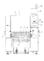
図1に示すように、この実施の形態例の電子部品実装装置1には、多数の電子部品フィーダ11を装着可能な一括交換台車10、電子部品実装装置1を制御するコントローラ20、図示しない電子部品実装部、後述するフィーダバンク12上の指示部13等が備えられている。
なお、電子部品実装装置1にはコントローラ20上の電子部品実装装置1の天板に当たる部分の上にコントローラ20のモニタ21が設けられている。また、電子部品実装装置1の天板上のモニタ21の後方には、電子部品実装装置1の作動、停止、警報等を報知するランプ30が設けられている。そして、この実施の形態例の指示装置は、上述のコントローラ20と指示部13とを主要構成とするものである。
【0030】
そして、電子部品実装装置1のカバー2内には、以下のような装置を備えた上述の電子部品実装部が備えられている。
すなわち、前記カバー2内には、電子部品フィーダ11の横並び方向に沿って、電子部品フィーダ11の奥側に、その両端部だけを図示した基板搬送装置3が設けられ、図中左右方向に基板を搬送(搬入、搬出)するようになっている。また、電子部品実装装置1のカバー2内には、図示しないが、吸着ヘッドを備えたヘッド部を水平で互いに直交するY方向とX方向とに移動するXY移動装置、該XY移動装置により移動されるヘッド部において吸着ヘッドをZ方向(上下方向)に移動させる昇降装置、前記ヘッド部において吸着ヘッドを左右に回転させる回転装置を備えている。
【0031】
そして、電子部品実装装置1おいては、前記吸着ヘッドがXY移動装置により、所定の電子部品フィーダ11の電子部品の供給位置に移動させた後に、昇降装置により下降して電子部品を吸着し、次いで、昇降装置により電子部品を吸着した吸着ヘッドを上昇させるとともに電子部品の実装時の角度に回転させる。
次いで、吸着ヘッドを、基板搬送装置3により搬入されるとともに所定位置に搬送された基板上の所定位置にXY移動装置により移動させ、昇降装置により下降させることで、基板上に電子部品を実装するようになっている。
また、電子部品実装装置1には、セットされた各電子部品フィーダ11を駆動するフィーダ駆動手段を有し、該フィーダ駆動手段の駆動力が電子部品フィーダ11に伝動されて、電子部品フィーダ11に格納された電子部品を電子部品フィーダ11の電子部品供給位置に送るようになっている。
【0032】
また、上記一括交換台車10には、複数の電子部品フィーダ11を装着するフィーダバンク12が備えられている。図2に概略を示すように、フィーダバンク12は、電子部品フィーダ11が載置される底板部12aと、該底板部12aに接続されるとともに、電子部品フィーダ11の先端面が当接するとともに、フィーダバンク12の左右に延在する当接板部12bと、電子部品フィーダ11の後部の下側に設けられた図示しない固定手段が固定される図示しない位置決め固定部とを備えている。
そして、前記当接板部12bには、異なる幅の電子部品フィーダ11のうちの最小幅の電子部品フィーダ11が、ほとんど隙間無く左右に配置できる間隔で多数の位置決めピン孔12cが形成されている。この位置決めピン孔12cには、電子部品フィーダ11の先端面に設けられた図示しない基準ピン(係合手段)が挿入されて電子部品フィーダが位置決めされるようになっている。従って、電子部品フィーダ11は、位置決めピン孔12cに基準ピンが挿入され、かつ、上述の位置決め固定部に固定手段が固定されることで、フィーダバンクに位置決め固定されるようになっている。
【0033】
そして、前記フィーダバンク12の当接板部12bの上には、当接板部12bとほぼ同様に左右に延在する指示部13が設けられている。そして、指示部13の位置は、フィーダバンク12に電子部品フィーダ11を装着した状態で、電子部品フィーダ11の後部の上から見通せる位置となっている。また、一括交換台車10を電子部品実装装置1に取り付けた状態で、電子部品フィーダ11と基板搬送装置3との間の位置となっている。従って、指示部13は、電子部品フィーダ11を装着した状態でも、容易に視認できるようになっている。
【0034】
そして、指示部13の前面には、ナンバープレート14が設けられている。ナンバープレート14には、当接板部12bの各位置決めピン孔12cの真上となる位置に、それぞれ、数値が、たとえば、左から連番で表示されている。すなわち、ナンバープレートの各数値が、各位置決めピン孔12cの位置を示すようになっている。
そして、ナンバープレート14の各数値の上となる位置に、それぞれ視覚的指示手段となるLED15(light emitting diode)が、位置決めピン孔12c及びナンバープレート14の数値と、一対一で対応するように取り付けられている。
そして、これらLED15と前記ナンバープレート14とがフィーダポジションインジケータとなっている。そして、各LED15の点灯及び消灯は、前記コントローラ20により制御されるようになっている。
【0035】
また、フィーダバンク12は、一括交換台車10に設けられており、電子部品実装装置1本体に対して着脱自在となっているので、上記LED15の駆動を制御する図示しないドライバ回路と、コントローラ20とは、無線もしくは有線により接続された状態となっており、コントローラ20からLED15の点灯及び消灯を制御できるようになっている。
【0036】
そして、上述のようなXY移動装置、昇降装置、回転装置、基板搬送装置3、LED15、電子部品フィーダ11の後述する駆動手段等の電子部品実装装置中の各装置は、前記コントローラ20により制御されるようになっている。
コントローラ20は、データの入力及びコントローラの操作等を行うための各種キー等を備えた操作盤22と、データの入力及び出力に用いることが可能な着脱式の記憶媒体(フロッピーディスクや着脱可能なハードディスクやマグネティックオプティカルディスク(MO)、フラッシュメモリ等の不揮発性の半導体メモリなど)を備えた補助記憶装置23と、CPU、RAM、ROM等を備えた図示しない演算処理部と、各種データや電子部品搬送装置の作動状態等を表示する前記モニタ21等とを備えている。そして、コントローラ20のCPUが、ROMもしくは補助記憶装置23等に記憶された生産プログラムに基づいて、各種処理を行い、コントローラ20が電子部品実装装置を制御するようになっている。
【0037】
たとえば、コントローラ20は、予め、操作盤22や補助記憶装置23にセットされた記憶媒体等により入力された吸着データ、たとえば、基板上の電子部品のレイアウトを示すデータや、各電子部品フィーダのフィーダバンク12上の配置等のデータに基づいて、基板上に決められたレイアウトどおりに電子部品を実装するように上述の各装置等を制御するものである。なお、LED15の点灯及び消灯以外の制御は、基本的に周知のものである。
【0038】
また、コントローラ20においては、操作盤22等からフィーダバンク12のナンバープレート14の数値で示される電子部品フィーダ11の各設置位置に、どの電子部品フィーダ11を配置するかを設定できるようになっており、各電子部品フィーダ11(各電子部品フィーダ11に格納された各電子部品)と、それらの電子部品フィーダ11のフィーダバンク12上の装着位置とが、一対一で対応づけられたデータが、RAMや補助記憶装置23に記憶されるようになっている。
【0039】
各電子部品フィーダ11のフィーダバンク12上の配置を基板上の電子部品のレイアウト等に対応して決定する最適化プログラムにより、各電子部品フィーダ11のフィーダバンク12上の装着位置とが、一対一で対応づけられたデータが、RAMや補助記憶装置23に記憶されるようになっている。すなわち、各電子部品フィーダ11のフィーダバンク12上の装着位置は、マニュアル操作で設定することもでき、かつ、周知の最適化プログラムにより自動で設定することもできる。どちらにしても、コントローラ20に各電子部品フィーダ11のフィーダバンク12上の装着位置を示すデータが保存される。
【0040】
コントローラ20は、上述のデータに基づき、たとえば、一括交換台車10上のフィーダバンク12に電子部品フィーダ11を順次装着する際に、モニタ21及びLED15を制御するようになっている。
【0041】
また、コントローラ20においては、各電子部品フィーダ11の部品格納数が入力されるとともに、電子部品実装装置において各電子部品フィーダ11から部品が供給される毎に、部品格納数から供給された部品数を減算することにより、各電子部品フィーダの残量数を算出するようになっている。また、残量数に基づいて、モニタ21やLED15等を制御するようになっている。
【0042】
また、コントローラ20は、フィーダ駆動手段のマニュアル制御を可能としており、操作盤22からの指示に基づいてフィーダ駆動手段を制御できるようになっている。なお、前記フィーダ駆動手段は、上記当接板部12bの各位置決めピン孔の直下より少し手前の位置にそれぞれ配置されたフィーダノックピン(図示略)を、シリンダ装置、ソレノイド、モータ等のアクチュエータで上下動させるものである。そして、電子部品フィーダ11には、前記ノックピンの位置にリンク機構の末端部が配置され、ノックピンの上下動が伝動されて電子部品を移動させるようになっている。そして、コントローラ20は、前記ノックピンの上下動に基づいて上記LED15を制御するようになっている。
【0043】
以下に、前記コントローラ20、モニタ21及び指示部13等からなる電子部品実装装置の指示装置の動作について説明する。
まず、フィーダバンク12に各電子部品フィーダ11を装着する際の指示装置の動作を説明する。なお、この際には、フィーダバンク12を備えた一括交換台車10は、電子部品実装装置1本体から外された状態となっているが、取り付けた状態で電子部品フィーダ11をフィーダバンク12に装着するものとしても良い。
【0044】
そして、電子部品フィーダ11の装着においては、指示部13のLED15が表1に示すように動作する。
すなわち、上述のコントローラ20のRAMもしくは補助記憶装置23に記憶された各電子部品フィーダ11とフィーダバンク12の各装着位置を関連づけたデータ(電子部品実装装置を上述の電子部品実装部を制御するための吸着データの一部)に基づいて、次に装着すべき電子部品フィーダ11を示すコードもしくは名称(たとえば、電子部品フィーダ11に格納された電子部品の名称でも良く、電子部品フィーダ11を特定できるデータならば良い。)がモニタ21に表示される。すなわち、コントローラ20が、吸着データの中から上述のデータを読出して、モニタ21に出力する。
【0045】
また、ほぼ同時に、モニタ21に表示された電子部品フィーダ11のフィーダバンク12の装着位置のLED15がコントローラ20の制御の基に点灯する。すなわち、前記電子部品フィーダ11の基準ピンが挿入される位置決めピン孔12cのほぼ真上に配置されたLED15が連続的に点灯する。
また、前記電子部品フィーダ11には、幅の広いものがあり、基準ピンを位置決めピン孔12cに挿入した際に、その左右の位置決めピン孔12cを他の電子部品フィーダ11の基準ピンがさせない状態に占有してしまうものがある。そして、上記吸着データには、フィーダバンク12に装着される電子部品フィーダ11の幅のデータも含まれているので、コントローラ20は、装着される電子部品フィーダ11の幅のデータを読みとれるようになっている。
【0046】
なお、電子部品フィーダ11は、最小幅の電子部品フィーダ11の幅もしくはそれに近い値が基準幅とされるとともに、各電子部品フィーダ11の幅が基準幅のほぼ整数倍となるようにされている。従って、上記電子部品フィーダ11の幅のデータは、基準幅に対する倍率のデータでも良い。
そして、コントローラ20は、装着すべきい電子部品フィーダ11の幅のデータに基づいて、該電子部品フィーダ11の基準ピンが挿入される位置決めピン孔12cの周囲で、電子部品フィーダ11に排他的に占有される位置決めピン孔12cの真上にあるLED15を、上記基準ピンが挿入された位置決めピン孔12cの真上のLED15とは異なる指示方法として、点滅した状態に点灯させる。
【0047】
以上のことから、作業者は、モニタ21に表示されたコード等に対応する電子部品フィーダ11を、その基準ピンが点灯したLED15の下の位置決めピン孔に挿入されるようにして、フィーダバンク12に装着することで、正しい位置に電子部品フィーダ11を装着することができる。特に、幅の広い電子部品フィーダ11の場合には、点滅するLED15の範囲と電子部品フィーダ11の幅とを見比べながら電子部品フィーダ11をフィーダバンク12に装着することで、より正確に電子部品フィーダ11を装着することができる。
【0048】
また、LED15が点灯及び点滅することで、電子部品フィーダ11の装着位置を瞬時に知ることができるので、電子部品フィーダ11を容易、かつ、迅速に装着することができる。
また、幅の広い電子部品フィーダ11を装着する際には、その電子部品フィーダ11の基準ピンが挿入される位置決めピン孔12cと、隣にくる電子部品フィーダ11の基準ピンが挿入される位置決めピン孔12cとの間に、基準ピンが挿入されない位置決めピン孔12cがあることになり、基準ピンを挿入する位置決めピン孔12cを間違える可能性が高くなる。しかし、基準ピンが挿入されずに電子部品フィーダ11に排他的に占有される位置決めピン孔12cに対応するLED15が、基準ピンが挿入される位置決めピン孔12cと視覚的に異なる指示を行うことで、上述のような間違いを低減することができる。
【0049】
また、上述のように装着位置を間違える可能性が高い状態で、隣に既に電子部品フィーダ11が装着されている場合に、点滅するLED15の位置と、隣に既に装着された電子部品フィーダ11の位置を見比べることにより、既に装着された電子部品フィーダ11の装着位置が間違っているか否かを容易に確認することができる。また、これにより、一つの電子部品フィーダ11の装着位置を位置決めピン孔12c一つ分だけ間違った際に、その後に続けて装着される電子部品フィーダ11の装着位置が順にひとつずつずれてしまうような事態を防止することができる。
【0050】
次に、フィーダバンク12に各電子部品フィーダ11が装着されるとともに、一括交換台車10が電子部品実装装置1本体に設置され、電子部品の実装が開始されている状態での指示装置の動作を図3の表2及び表3を参照して説明する。
この際には、上述のようにコントローラにおいて、各電子部品フィーダ11における電子部品の残数量が算出されている。また、コントローラにおいては、生産プログラムのデータ入力において、基板生産画面データ切替という項目の部品残数設定の警告レベル入力値として、予め、電子部品フィーダ11における電子部品の残数量が少なくなったことを警告する際の残数量が入力されている。
【0051】
そして、コントローラ20においては、各電子部品フィーダ11において、設定された残数量と算出された残数量とを比較し、算出された残数量が設定された残数量以下となった電子部品フィーダ11がある場合に、その電子部品フィーダ11の基準ピンの挿入位置の真上にあるLED15を点滅表示するようになっている。
【0052】
さらに、電子部品の残数量が設定された残数量以下となった電子部品フィーダ11において、残数量が0となった場合には、上述のように点滅表示されていたLED15を連続して点灯するようにコントローラ20が制御するようになっている。なお、LED15を点灯や点滅させる際に、ランプ30を点灯するものとしても良い。
上述のようにLED15が作業中に、点滅もしくは点灯することにより、交換すべき電子部品フィーダ11が存在することがわかるとともに、その電子部品フィーダ11の装着位置を一目で瞬時にオペレータに認識させることができる。また、LED15が点滅しているか連続して点灯しているかで、すぐに電子部品フィーダを交換すべきなのか、まだ、少し時間的に余裕があるのかを判断することができる。
【0053】
次に、マニュアル制御で、上述のようにフィーダ駆動手段のノックピン制御を行う際の指示装置の動作を図3の表4を参照して説明する。
この際には、マニュアル制御によるノックピン制御に必要な事項として、操作盤22から操作するノックピンの位置データが入力されるとともに、フィーダの種類等が入力される。
そして、コントローラ20は、操作盤22からの入力データと指示とに基づき、指定された位置のノックピンを上下動させるとともに、該ノックピンの位置に対応するLED15、すなわち、ノックピンの上方の位置決めピン孔12cのさらに上にあるLED15の点灯及び消灯を行う。すなわち、ノックピンが上昇した場合には、LED15を点灯させ、ノックピンが下降した際には、LED15を消灯させる。
【0054】
これにより、操作盤22から指定した位置にある電子部品フィーダ11もしくは電子部品フィーダ11が装着されていない状態で指定した位置にあるノックピンと、LED15の点灯と消灯とを見比べることにより、指定された位置のノックピンが正常に動作しているか否かを容易に確認することができる。
【発明の効果】
請求項1記載の本発明の電子部品実装装置の指示装置によれば、幅の異なるものがある電子部品フィーダをそれぞれフィーダバンクに装着する際に、瞬時に装着位置を認識して、短時間で電子部品フィーダを正しい装着位置に装着できるとともに、電子部品フィーダの占有範囲を瞬時に認識できるので、電子部品フィーダの装着時に、装着位置をより容易かつ確実に認識して、正しい装着位置に正確かつ迅速に電子部品フィーダを装着することができる。また、装着すべき電子部品フィーダと異なる幅の電子部品フィーダを間違って装着してしまうようなミスも確実に防止できる。
【0055】
請求項2記載の本発明の電子部品実装装置の指示装置によれば、視覚的指示手段が電子部品実装装置のフィーダバンクに装着された電子部品フィーダの後部の上側から見通せる位置に設けられているので、フィーダバンクに電子部品が装着されていない状態ではもちろん容易にオペレータが視認することができるとともに、電子部品フィーダをフィーダバンクに装着した状態でも容易に視認することができる。
また、視覚的指示手段の設置位置は、電子部品フィーダではなく、電子部品実装装置であり、電子部品フィーダは、既存のものを用いることができる。
【0056】
請求項3記載の本発明の電子部品実装装置の指示装置によれば、装着すべき電子部品フィーダの装着位置が視覚的指示手段に視覚的に指示できるので、電子部品フィーダの装着位置を瞬時に認識できる。また、電子部品フィーダを装着した後にも、請求項2記載の構成により、視覚的指示手段を容易に視認することができるので、たとえば、装着された電子部品フィーダと視覚的指示手段とを見比べることにより、装着位置が正しいか否かを容易に確認することができる。
【0057】
請求項4記載の本発明の電子部品実装装置の指示装置によれば、電子部品フィーダにおいて、電子部品の供給が完了して空の状態の電子部品フィーダの装着位置が視覚的指示手段により視覚的に指示されるので、空になって交換する必要のある電子部品フィーダの装着位置を瞬時に認識することができる。従って、供給すべき電子部品が無くなった電子部品フィーダの交換を容易かつ迅速に、他の電子部品フィーダと間違えることなく、行うことができる。
【0058】
請求項5記載の本発明の電子部品実装装置の指示装置によれば、電子部品フィーダにおいて、電子部品の残量数が少なくなった電子部品フィーダの装着位置が視覚的指示手段により視覚的に指示されるので、次に、交換する必要のある電子部品フィーダの装着位置を瞬時に認識することができる。従って、電子部品フィーダの交換を容易かつ迅速に、他の電子部品フィーダと間違えることなく、行うことができる。
【0059】
請求項6記載の本発明の電子部品実装装置の指示装置によれば、たとえば、請求項1記載のように第一の視覚的指示手段と第二の視覚的指示手段とのように異なる方法で指示を出力するような場合に、連続的な指示と、断続的な指示とにより、指示の方法を変えることができる。また、電子部品フィーダの電子部品の残数量が所定量以下となった場合と、0となった場合とで、断続的指示と連続的指示とを切り替えるのも有効である。
【図面の簡単な説明】
【図1】本発明の実施の形態例の電子部品実装装置の正面図である。
【図2】上記例の電子部品実装装置の指示装置の視覚的認識手段となるLEDを備えたフィーダバンクを示すものである。
【図3】上記例の電子部品実装装置におけるLEDの点灯条件等を説明するための図表である。
【符号の説明】
11 電子部品フィーダ
12 フィーダバンク
12c 位置決めピン孔
15 LED(視覚認識手段)[0001]
BACKGROUND OF THE INVENTION
The present invention relates to an instruction device for an electronic component mounting apparatus that outputs an instruction based on information about an electronic component feeder that supplies the electronic component in the electronic component mounting apparatus.
[0002]
[Prior art]
Generally, an electronic component mounting apparatus has a suction nozzle that holds an electronic component in a sucked state, and the electronic component is transported to a mounting position on a printed board by the suction nozzle, and the electronic component is mounted on the printed board.
[0003]
Further, in the electronic component mounting apparatus, a plurality of electronic component feeders for supplying electronic components one by one to the suction position of the suction nozzle are mounted in a state of being arranged in a horizontal row. The electronic component mounting apparatus is provided with a feeder bank for mounting a plurality of electronic component feeders in a horizontal row. Each electronic component feeder includes positioning fixing means for attaching the corresponding electronic component feeder itself to the feeder bank, and a positioning reference pin inserted into a positioning pin hole provided for each slot on the feeder bank. It has. These electronic component feeders are positioned by the positioning and fixing means and the reference pin, and are fixed to the feeder bank.
[0004]
The electronic component feeder is prepared with a width that varies depending on the size of the component to be supplied. Positioning members such as positioning pin holes of the feeder bank are arranged corresponding to the electronic component feeder with the minimum width. Therefore, when an electronic component feeder having a width wider than the electronic component feeder having the smallest width is mounted on the feeder bank, the positioning pin hole portion around the positioning pin hole into which the reference pin of the wide electronic component feeder is inserted The electronic component feeder may be exclusively occupied by a wide electronic component feeder, and another electronic component feeder cannot be mounted in the positioning pin hole.
[0005]
In the electronic component mounting apparatus, the suction nozzle is moved by a pre-programmed operation, so that the suction nozzle is moved so as to go to a predetermined suction position of the feeder bank. At this time, an electronic component feeder for supplying the predetermined electronic component needs to be disposed at the suction position. Accordingly, each electronic component feeder needs to be mounted at a predetermined position of the feeder bank. In other words, in the electronic component mounting apparatus, it is necessary to store data indicating which electronic component is supplied by the electronic component feeder arranged at each position of the feeder bank.
[0006]
Note that the working time can be shortened by determining the mounting position of each electronic component feeder in accordance with the layout of the electronic components on the substrate, for example, so as to shorten the moving distance of the suction nozzle. When there are a plurality of suction nozzles, the work time can be shortened by changing the arrangement of the electronic component feeder correspondingly. Therefore, the arrangement of each electronic component feeder on the feeder bank can be set by the operator, and the optimal optimization can reduce the work time corresponding to the layout of the electronic components on the board by a well-known optimization program. The position of each electronic component feeder can be set so as to achieve a proper arrangement.
[0007]
[Problems to be solved by the invention]
By the way, when the electronic component feeder is mounted on the feeder bank, it is necessary to mount the electronic component feeder at a preset position for each electronic component feeder as described above. Therefore, for example, in order to make the mounting position of the electronic component feeder easy to understand, there are cases where a number plate is installed in the feeder bank corresponding to each positioning pin hole of the feeder bank. Then, the mounting position of the electronic component feeder is confirmed by looking at the value on the license plate when the electronic component feeder is mounted.
[0008]
However, if the electronic component feeder is mounted while looking for the value on the license plate indicating the position where the electronic component feeder should be mounted, the mounting position of the electronic component feeder cannot be found instantaneously, and workability is improved. The problem is that it takes a little time. Further, since the positioning pin holes are arranged in a line at a relatively narrow interval, there is a possibility that the positioning pin holes may be erroneously inserted into the adjacent positioning pin holes when the reference pin is inserted.
[0009]
In addition, in the electronic component mounting apparatus, the remaining number of electronic components is obtained from the number of electronic components stored in the electronic component feeder and the number of supplied electronic components, and the remaining electronic component feeder is reduced. In addition, there is a demand for an electronic component feeder that has no electronic components. However, even in this case, in the electronic component mounting apparatus, it is not possible to instantly know where the electronic component feeder with fewer or no electronic components is installed, and it takes time and effort to search for the corresponding electronic component feeder. It took time.
[0010]
An object of the present invention is to instantly recognize information on electronic component feeders such as the mounting position of each electronic component feeder and the mounting positions of electronic component feeders in which the number of electronic components is reduced or missing in an electronic component mounting apparatus. It is an object of the present invention to provide an instruction device for an electronic component mounting apparatus that gives instructions as possible.
[0011]
[Means for Solving the Problems]
[0012]
The indicating device for an electronic component mounting apparatus according to the first aspect of the present invention is capable of mounting a plurality of
Visual instruction means (LED 15) provided corresponding to each positioning means of the feeder bank and instructing to visually recognize the mounting position of the electronic component feeder to be mounted on the feeder bank,
When mounting an electronic component feeder having a width that exclusively occupies the range of a plurality of positioning means adjacent to each other at the time of mounting to the feeder bank,Visual indication meansVisual instruction means corresponding to positioning means with which the engagement means of the electronic component feeder is engaged outputs a visual instruction,
And the visual indicating means corresponding to the positioning means exclusively occupied by the electronic component feeder without engaging the engaging means of the electronic component feeder of the visual indicating means is the engagement. A visual instruction is output in a different manner from the visual instruction means corresponding to the positioning means with which the means engages.
[0013]
According to the above configuration, when the electronic component feeder is installed in the feeder bank, the installation position of the electronic component feeder on the feeder bank is provided corresponding to each positioning means that determines the position of the electronic component feeder of the feeder bank. It is visually instructed by the visual instruction means. Therefore, there is no need to search for a specific value on the license plate provided in the feeder bank and confirm the mounting position, and the positioning means corresponding to the visual instruction means outputting the visual instructions can be recognized instantly. can do.
[0014]
Further, when the width of the electronic component feeder to be mounted is wide, it corresponds to the positioning means of the feeder bank with which the engaging means of the electronic component feeder is engaged.Visual indication meansOutputs instructions as described above. Furthermore, it corresponds to the positioning means exclusively occupied by the wide electronic component feeder so that no other electronic component feeder can be mounted by the aforementioned wide electronic component feeder.Visual indication meansBut,Corresponding to the positioning means with which the engaging means engagesA visual instruction is output by a method different from the visual instruction means. Therefore, when mounting a wide electronic component feeder,Corresponding to the positioning means with which the engaging means engagesThe visual indicating means can instantly recognize the position of the positioning means for engaging the engaging means, and can instantly recognize the range occupied when the electronic component feeder is mounted on the feeder bank.
[0015]
For these reasons, when mounting electronic component feeders with different widths to the feeder bank, the mounting position can be recognized instantly and the electronic component feeder can be mounted at the correct mounting position in a short time. Since the occupying range of the feeder can be recognized instantly, the mounting position can be more easily and reliably recognized when the electronic component feeder is mounted, and the electronic component feeder can be mounted accurately and quickly at the correct mounting position. In addition, it is possible to reliably prevent mistakes in which an electronic component feeder having a width different from that of the electronic component feeder to be mounted is erroneously mounted.
[0016]
When electronic component feeders are sequentially mounted on a feeder bank, the electronic component mounting apparatus displays, for example, a code or name indicating the electronic component feeder to be mounted next on its monitor. Thus, the electronic component feeder to be mounted next can be understood.
The visual instruction means is, for example, a light-emitting body such as various lamps, a mechanical device capable of visually recognizing a member such as a member, or a display such as a liquid crystal display. Further, in the above-described mechanical device, a drive device used for movement of a member such as a projecting member is a motor, an air cylinder, a solenoid, or the like.
[0017]
Also,Corresponding to the positioning means with which the engaging means engagesWith visual indication meansCorresponds to the positioning means exclusively occupied by the electronic component feederFor example, when the visual indicating means is a illuminant, the visual indicating means is different from the visual indicating means such that light is emitted in different colors, one is continuously lit, and the other is blinking. It is turned on, or the way of blinking is changed between one and the other. In addition, when the visual instruction means is a mechanical device, for example, the color or shape of the member that appears or is changed, or one of the members is kept in the state where the member is protruded, and the other is repeatedly raised or lowered. To do. In addition, in a display such as a liquid crystal display, the visual instruction means changes the color and shape of the display image, or continuously outputs the same image on one side and outputs different images while switching on the other side. is there.
In addition, the feeder bank may be fixedly provided on the electronic component mounting apparatus, or may be provided in a batch exchange cart such as a floor trolley type that is detachable and movable with respect to the electronic component mounting apparatus body. It is good as it is. Further, when the batch exchange cart has a feeder bank, it is preferable to provide a visual instruction means on the batch exchange cart side.
[0018]
An instruction device for an electronic component mounting apparatus according to a second aspect of the present invention comprises:Claim 1In the pointing device of the electronic component mounting device,
The visual indication means comprises:It is provided in the position which can be seen from the upper part of the rear part of the electronic component feeder with which the said feeder bank was mounted | worn.
[0019]
According to the above configuration, since the visual instruction means is provided at a position that can be seen from the upper side of the rear part of the electronic component feeder mounted on the feeder bank of the electronic component mounting apparatus, the electronic component is not mounted on the feeder bank. Then, of course, the operator can easily visually recognize the electronic component feeder, and even when the electronic component feeder is mounted on the feeder bank.
Further, the installation position of the visual instruction means is not an electronic component feeder but an electronic component mounting apparatus, and an existing electronic component feeder can be used. In addition, as described above, the installation position of the visual instruction means may be a collective exchange cart of the electronic component mounting apparatus.
[0020]
Further, the specific installation position of the visual instruction device is, for example, an electronic component feeder mounted on a feeder bank and a substrate transfer device that is provided in the electronic component mounting apparatus and carries a substrate on which the electronic component is mounted. It is good also as what is provided in the position which can be visually recognized from the upper back of an electronic component feeder. Further, the visual instruction means must be able to easily recognize the mounting position of the electronic component feeder corresponding to the instruction when the instruction is output, and is provided in the vicinity of the mounting position of each electronic component of the feeder bank. Preferably it is. In the case of a display such as a liquid crystal display, it may be formed across the mounting positions of a plurality of electronic component feeders in the feeder bank.
The visual instruction means may be any of a light emitter, a mechanical device, a display, etc. as described above.
[0021]
According to a third aspect of the present invention, there is provided an instruction device for an electronic component mounting apparatus according to the present invention.1 or 2In the electronic device mounting apparatus indicating device described above,
When the visual instruction means mounts the electronic component feeder on the feeder bank, the visual instruction means instructs to visually recognize a mounting position of the feeder bank to which the electronic component feeder is to be mounted.
[0022]
According to the above configuration, since the mounting position of the electronic component feeder to be mounted can be visually instructed to the visual instruction means, the mounting position of the electronic component feeder can be instantly recognized. Further, the visual instruction means can be easily visually recognized even after the electronic component feeder is mounted, so that, for example, the mounted electronic component feeder is compared with the visual instruction means. Thus, it can be easily confirmed whether or not the mounting position is correct.
[0023]
According to a fourth aspect of the present invention, there is provided the pointing device for the electronic component mounting apparatus according to the present invention, wherein the visual pointing means is the mounting position of the electronic component feeder in which the supply of the electronic component is completed among the electronic component feeders mounted on the feeder bank. Is instructed so that it can be visually recognized.
[0024]
According to the above configuration, in the electronic component feeder, the mounting position of the electronic component feeder in an empty state after the supply of the electronic component is completed is visually instructed by the visual instruction means. It is possible to instantly recognize the mounting position of a certain electronic component feeder. Therefore, it is possible to easily and quickly replace an electronic component feeder that has no electronic components to be supplied without making a mistake with other electronic component feeders.
[0025]
The electronic component mounting apparatus indicating device according to
[0026]
According to the above configuration, in the electronic component feeder, the mounting position of the electronic component feeder in which the number of remaining electronic components is reduced is visually instructed by the visual instruction means. The mounting position of the component feeder can be recognized instantly. Therefore, the replacement of the electronic component feeder can be performed easily and quickly without making a mistake with other electronic component feeders.
[0027]
An instruction device for an electronic component mounting apparatus according to a sixth aspect of the present invention is the pointing device for an electronic component mounting apparatus according to any one of the first to fifth aspects,
The controller
A visual indication means corresponding to the positioning means with which the engagement means of the electronic component feeder is engaged;
An instruction that the visual indicating means corresponding to the positioning means exclusively occupied by the electronic component feeder is intermittently interrupted without engaging the engaging means of the electronic component feeder;
And switching the output.
[0028]
According to the above configuration, for example, the visual instruction means corresponding to the positioning means engaged by the engaging means and the visual instruction corresponding to the positioning means exclusively occupied by the electronic component feeder as described in claim 1 When outputting instructions in a different way, such asThe controller is exclusive to the electronic component feeder without engaging the visual indicating means that the visual indicating means corresponding to the positioning means with which the engaging means of the electronic component feeder engages, and the engaging means of the electronic component feeder. The visual instruction means corresponding to the positioning means that are occupied automatically switch between the visual interruption instructions and output.Thus, the instruction method can be changed. It is also effective to switch between an intermittent instruction and a continuous instruction when the remaining quantity of electronic components in the electronic component feeder is less than or equal to a predetermined amount and when it is zero.
Note that the continuous instruction is, for example, a state in which the visual instruction means is lit when the light emitter is used, and the intermittent instruction is a state in which the visual instruction means is flashing, but the visual instruction means is a mechanical device. The continuous instruction is to hold the state where the member has come out, and the intermittent instruction is a state in which the member is repeatedly raised and lowered. In the display, the continuous instruction is to display the same image, and the intermittent instruction is to switch and display different images.
[0029]
DETAILED DESCRIPTION OF THE INVENTION
Hereinafter, an instruction device for an electronic component mounting apparatus according to an embodiment of the present invention will be described with reference to the drawings.
As shown in FIG. 1, an electronic component mounting apparatus 1 according to this embodiment includes a
The electronic component mounting apparatus 1 is provided with a
[0030]
And in the
That is, in the
[0031]
And in the electronic component mounting apparatus 1, after the said adsorption | suction head is moved to the supply position of the electronic component of the predetermined
Next, the electronic component is mounted on the substrate by moving the suction head to a predetermined position on the substrate carried by the
In addition, the electronic component mounting apparatus 1 has feeder driving means for driving each
[0032]
The
A large number of
[0033]
On the
[0034]
A
Then, LEDs 15 (light emitting diodes) serving as visual indicating means are attached to the positions above the numerical values of the
These
[0035]
Further, the
[0036]
And each apparatus in electronic component mounting apparatuses, such as the above-mentioned XY movement apparatus, a raising / lowering apparatus, a rotation apparatus, the board |
The
[0037]
For example, the
[0038]
Further, in the
[0039]
According to an optimization program that determines the arrangement of each
[0040]
Based on the above data, the
[0041]
Further, in the
[0042]
Further, the
[0043]
Hereinafter, the operation of the instruction device of the electronic component mounting apparatus including the
First, the operation of the instruction device when each
[0044]
When the
That is, data relating each mounting position of each
[0045]
At substantially the same time, the
The
[0046]
The
Then, the
[0047]
From the above, the operator inserts the
[0048]
Further, since the
Further, when mounting the wide
[0049]
In addition, when the
[0050]
Next, each
At this time, as described above, the remaining quantity of electronic components in each
[0051]
In the
[0052]
Furthermore, in the
As described above, when the
[0053]
Next, the operation of the pointing device when performing the knock pin control of the feeder driving means as described above by manual control will be described with reference to Table 4 in FIG.
At this time, the position data of the knock pin operated from the operation panel 22 and the type of feeder are input as necessary items for the knock pin control by manual control.
The
[0054]
As a result, the
【The invention's effect】
According to the instruction device of the electronic component mounting apparatus of the first aspect of the present invention, when the electronic component feeders having different widths are mounted on the feeder bank, the mounting position is recognized instantly, and in a short time. Since the electronic component feeder can be mounted at the correct mounting position and the occupation range of the electronic component feeder can be recognized instantly, the mounting position can be recognized more easily and reliably when mounting the electronic component feeder, and the correct mounting position can be accurately and accurately The electronic component feeder can be quickly mounted. In addition, it is possible to reliably prevent mistakes in which an electronic component feeder having a width different from that of the electronic component feeder to be mounted is erroneously mounted.
[0055]
According to the instruction device for the electronic component mounting apparatus of the second aspect of the present invention, the visual instruction means is provided at a position that can be seen from above the rear part of the electronic component feeder mounted on the feeder bank of the electronic component mounting apparatus. Therefore, the operator can easily recognize the electronic component when the electronic component is not mounted on the feeder bank, and can easily be visually recognized even when the electronic component feeder is mounted on the feeder bank.
Further, the installation position of the visual instruction means is not an electronic component feeder but an electronic component mounting apparatus, and an existing electronic component feeder can be used.
[0056]
According to the instruction device of the electronic component mounting apparatus of the third aspect of the present invention, since the mounting position of the electronic component feeder to be mounted can be visually instructed to the visual instruction means, the mounting position of the electronic component feeder is instantaneously determined. Can be recognized. Further, the visual instruction means can be easily visually recognized even after the electronic component feeder is mounted, so that, for example, the mounted electronic component feeder is compared with the visual instruction means. Thus, it can be easily confirmed whether or not the mounting position is correct.
[0057]
According to the indicating device for an electronic component mounting apparatus of the present invention as set forth in
[0058]
According to the instruction device for an electronic component mounting apparatus of the present invention as set forth in
[0059]
According to the indication device of the electronic component mounting apparatus of the present invention described in
[Brief description of the drawings]
FIG. 1 is a front view of an electronic component mounting apparatus according to an embodiment of the present invention.
FIG. 2 shows a feeder bank provided with LEDs serving as visual recognition means of the pointing device of the electronic component mounting apparatus of the above example.
FIG. 3 is a table for explaining LED lighting conditions and the like in the electronic component mounting apparatus of the above example.
[Explanation of symbols]
11 Electronic parts feeder
12 Feeder Bank
12c Positioning pin hole
15 LED (visual recognition means)
Claims (6)
前記フィーダバンクの各位置決め手段毎に対応して設けられ、かつ、装着すべき電子部品フィーダのフィーダバンク上の装着位置を視覚的に認識させるように指示する視覚的指示手段を備え、
装着時に複数の互いに隣接する位置決め手段の範囲を排他的に占有する幅を有する電子部品フィーダをフィーダバンクに装着する際に、前記視覚的指示手段のうちの前記電子部品フィーダの係合手段が係合する位置決め手段に対応する視覚的指示手段が視覚的な指示を出力し、
かつ、前記視覚的指示手段のうちの前記電子部品フィーダの係合手段に係合することなく、前記電子部品フィーダに排他的に占有される位置決め手段に対応する視覚的指示手段が、前記係合手段が係合する位置決め手段に対応する視覚的指示手段と異なる方法で視覚的な指示を出力することを特徴とする電子部品実装装置の指示装置。A plurality of electronic component feeders having different widths can be mounted, and a feeder bank provided with positioning means for determining the position of the electronic component feeder by engaging engagement means provided in the electronic component feeder. An instruction device for an electronic component mounting apparatus,
Provided for each positioning means of the feeder bank, and provided with visual instruction means for instructing to visually recognize the mounting position on the feeder bank of the electronic component feeder to be mounted,
When the electronic component feeder having a width that exclusively occupies the range of a plurality of adjacent positioning means when mounted is mounted on the feeder bank, the electronic component feeder engaging means of the visual indicating means is engaged. The visual instruction means corresponding to the positioning means to match outputs a visual instruction,
And the visual indicating means corresponding to the positioning means exclusively occupied by the electronic component feeder without engaging the engaging means of the electronic component feeder of the visual indicating means is the engagement. An instruction device for an electronic component mounting apparatus, characterized in that a visual instruction is output by a method different from the visual instruction means corresponding to the positioning means with which the means engages.
前記電子部品フィーダの係合手段が係合する位置決め手段に対応する視覚的指示手段が視覚的に連続する指示と、
前記電子部品フィーダの係合手段に係合することなく、前記電子部品フィーダに排他的に占有される位置決め手段に対応する視覚的指示手段が視覚的に断続する指示と、
を切り替えて出力することを特徴とする請求項1〜5のいずれか一つに記載の電子部品実装装置の指示装置。 The controller
A visual indication means corresponding to the positioning means with which the engagement means of the electronic component feeder is engaged;
An instruction that the visual indicating means corresponding to the positioning means exclusively occupied by the electronic component feeder is intermittently interrupted without engaging the engaging means of the electronic component feeder;
The indication device for an electronic component mounting apparatus according to any one of claims 1 to 5, wherein:
Priority Applications (1)
| Application Number | Priority Date | Filing Date | Title |
|---|---|---|---|
| JP2000141950A JP4412809B2 (en) | 2000-05-15 | 2000-05-15 | Instruction device for electronic component mounting equipment |
Applications Claiming Priority (1)
| Application Number | Priority Date | Filing Date | Title |
|---|---|---|---|
| JP2000141950A JP4412809B2 (en) | 2000-05-15 | 2000-05-15 | Instruction device for electronic component mounting equipment |
Publications (3)
| Publication Number | Publication Date |
|---|---|
| JP2001326494A JP2001326494A (en) | 2001-11-22 |
| JP2001326494A5 JP2001326494A5 (en) | 2007-06-28 |
| JP4412809B2 true JP4412809B2 (en) | 2010-02-10 |
Family
ID=18648998
Family Applications (1)
| Application Number | Title | Priority Date | Filing Date |
|---|---|---|---|
| JP2000141950A Expired - Fee Related JP4412809B2 (en) | 2000-05-15 | 2000-05-15 | Instruction device for electronic component mounting equipment |
Country Status (1)
| Country | Link |
|---|---|
| JP (1) | JP4412809B2 (en) |
Families Citing this family (4)
| Publication number | Priority date | Publication date | Assignee | Title |
|---|---|---|---|---|
| JP4127366B2 (en) * | 2002-05-24 | 2008-07-30 | Juki株式会社 | Electronic component mounting equipment |
| JP3860511B2 (en) * | 2002-07-09 | 2006-12-20 | 山形カシオ株式会社 | Collective exchange cart, component mounting system, and connection confirmation method |
| JP2005347352A (en) * | 2004-05-31 | 2005-12-15 | Yamaha Motor Co Ltd | Feeder replacement carriage and packaging machine equipped therewith |
| JP5243973B2 (en) * | 2009-01-09 | 2013-07-24 | 富士機械製造株式会社 | Component mounting board production method and component mounting board production system |
-
2000
- 2000-05-15 JP JP2000141950A patent/JP4412809B2/en not_active Expired - Fee Related
Also Published As
| Publication number | Publication date |
|---|---|
| JP2001326494A (en) | 2001-11-22 |
Similar Documents
| Publication | Publication Date | Title |
|---|---|---|
| JP5424686B2 (en) | Circuit board work system | |
| JP4545488B2 (en) | Mounting machine | |
| JP6027734B2 (en) | Electronic component feeder | |
| JP4412809B2 (en) | Instruction device for electronic component mounting equipment | |
| WO2014097389A1 (en) | Component-mounting machine | |
| JP7232981B2 (en) | Mounting position display method for component mounter and parts feeder | |
| JP5342230B2 (en) | Electronic component mounting apparatus and electronic component mounting method | |
| JP4455172B2 (en) | Mounting machine | |
| KR20070024486A (en) | Sewing machine | |
| JP5722123B2 (en) | Board work machine | |
| JP6974211B2 (en) | Parts mounting machine | |
| JP7163413B2 (en) | mounting system | |
| US11304348B2 (en) | Surface mounting device and an informing method | |
| JP2013229374A (en) | Component mounting device | |
| JP2000209000A (en) | Electronic component mounting apparatus | |
| JP5185796B2 (en) | Electronic component mounting device | |
| JP4127366B2 (en) | Electronic component mounting equipment | |
| JP6681190B2 (en) | Control device for feeder | |
| JP7349392B2 (en) | Control device, mounting system and control method | |
| WO2021181576A1 (en) | Management device, installation-related device, installation system, management method, and method for controlling installation-related device | |
| CN110418567B (en) | Management system and management method | |
| JP4900170B2 (en) | Warning light for component mounting related devices and component mounting related devices | |
| JP2001274592A (en) | Tray supplying apparatus | |
| CN117378292A (en) | Belt feeder trades to produce governing system | |
| JP5517784B2 (en) | Support pin arrangement data creation device |
Legal Events
| Date | Code | Title | Description |
|---|---|---|---|
| A521 | Written amendment |
Free format text: JAPANESE INTERMEDIATE CODE: A523 Effective date: 20070515 |
|
| A621 | Written request for application examination |
Free format text: JAPANESE INTERMEDIATE CODE: A621 Effective date: 20070515 |
|
| A131 | Notification of reasons for refusal |
Free format text: JAPANESE INTERMEDIATE CODE: A131 Effective date: 20090728 |
|
| A977 | Report on retrieval |
Free format text: JAPANESE INTERMEDIATE CODE: A971007 Effective date: 20090730 |
|
| A521 | Written amendment |
Free format text: JAPANESE INTERMEDIATE CODE: A523 Effective date: 20090928 |
|
| TRDD | Decision of grant or rejection written | ||
| A01 | Written decision to grant a patent or to grant a registration (utility model) |
Free format text: JAPANESE INTERMEDIATE CODE: A01 Effective date: 20091020 |
|
| A01 | Written decision to grant a patent or to grant a registration (utility model) |
Free format text: JAPANESE INTERMEDIATE CODE: A01 |
|
| A61 | First payment of annual fees (during grant procedure) |
Free format text: JAPANESE INTERMEDIATE CODE: A61 Effective date: 20091117 |
|
| FPAY | Renewal fee payment (event date is renewal date of database) |
Free format text: PAYMENT UNTIL: 20121127 Year of fee payment: 3 |
|
| R150 | Certificate of patent or registration of utility model |
Ref document number: 4412809 Country of ref document: JP Free format text: JAPANESE INTERMEDIATE CODE: R150 Free format text: JAPANESE INTERMEDIATE CODE: R150 |
|
| FPAY | Renewal fee payment (event date is renewal date of database) |
Free format text: PAYMENT UNTIL: 20121127 Year of fee payment: 3 |
|
| FPAY | Renewal fee payment (event date is renewal date of database) |
Free format text: PAYMENT UNTIL: 20131127 Year of fee payment: 4 |
|
| LAPS | Cancellation because of no payment of annual fees |