JP4409441B2 - Thermal tympanic thermometer tip - Google Patents
Thermal tympanic thermometer tip Download PDFInfo
- Publication number
- JP4409441B2 JP4409441B2 JP2004560260A JP2004560260A JP4409441B2 JP 4409441 B2 JP4409441 B2 JP 4409441B2 JP 2004560260 A JP2004560260 A JP 2004560260A JP 2004560260 A JP2004560260 A JP 2004560260A JP 4409441 B2 JP4409441 B2 JP 4409441B2
- Authority
- JP
- Japan
- Prior art keywords
- sensor
- tympanic thermometer
- nozzle
- temperature
- probe
- Prior art date
- Legal status (The legal status is an assumption and is not a legal conclusion. Google has not performed a legal analysis and makes no representation as to the accuracy of the status listed.)
- Expired - Fee Related
Links
- 239000000523 sample Substances 0.000 claims abstract description 66
- 239000000463 material Substances 0.000 claims description 13
- 230000005855 radiation Effects 0.000 claims description 11
- 230000005611 electricity Effects 0.000 claims description 2
- 229910001092 metal group alloy Inorganic materials 0.000 claims description 2
- 238000009413 insulation Methods 0.000 claims 2
- 239000012774 insulation material Substances 0.000 claims 2
- 230000004907 flux Effects 0.000 abstract description 9
- 238000000034 method Methods 0.000 abstract description 3
- 239000011810 insulating material Substances 0.000 abstract 1
- 210000003454 tympanic membrane Anatomy 0.000 description 14
- 230000036760 body temperature Effects 0.000 description 12
- 238000009529 body temperature measurement Methods 0.000 description 11
- 230000008859 change Effects 0.000 description 8
- 238000012546 transfer Methods 0.000 description 8
- 238000009826 distribution Methods 0.000 description 6
- 238000013461 design Methods 0.000 description 4
- 239000011521 glass Substances 0.000 description 4
- 239000004033 plastic Substances 0.000 description 4
- 229920003023 plastic Polymers 0.000 description 4
- 238000001514 detection method Methods 0.000 description 3
- 210000000883 ear external Anatomy 0.000 description 3
- 238000004519 manufacturing process Methods 0.000 description 3
- 238000005259 measurement Methods 0.000 description 3
- 239000012528 membrane Substances 0.000 description 3
- 241000894006 Bacteria Species 0.000 description 2
- 206010050337 Cerumen impaction Diseases 0.000 description 2
- 238000004458 analytical method Methods 0.000 description 2
- 210000002939 cerumen Anatomy 0.000 description 2
- 230000001684 chronic effect Effects 0.000 description 2
- 238000003745 diagnosis Methods 0.000 description 2
- 238000010586 diagram Methods 0.000 description 2
- 230000000694 effects Effects 0.000 description 2
- 238000010438 heat treatment Methods 0.000 description 2
- 239000007769 metal material Substances 0.000 description 2
- 238000012986 modification Methods 0.000 description 2
- 230000004048 modification Effects 0.000 description 2
- -1 polypropylene Polymers 0.000 description 2
- 208000024891 symptom Diseases 0.000 description 2
- 238000012360 testing method Methods 0.000 description 2
- 238000003466 welding Methods 0.000 description 2
- 208000031295 Animal disease Diseases 0.000 description 1
- 241001465754 Metazoa Species 0.000 description 1
- 239000004698 Polyethylene Substances 0.000 description 1
- 239000004743 Polypropylene Substances 0.000 description 1
- 206010037660 Pyrexia Diseases 0.000 description 1
- 239000000853 adhesive Substances 0.000 description 1
- 230000001070 adhesive effect Effects 0.000 description 1
- 229910052782 aluminium Inorganic materials 0.000 description 1
- XAGFODPZIPBFFR-UHFFFAOYSA-N aluminium Chemical compound [Al] XAGFODPZIPBFFR-UHFFFAOYSA-N 0.000 description 1
- 230000005540 biological transmission Effects 0.000 description 1
- 230000002596 correlated effect Effects 0.000 description 1
- 230000007812 deficiency Effects 0.000 description 1
- 201000010099 disease Diseases 0.000 description 1
- 208000037265 diseases, disorders, signs and symptoms Diseases 0.000 description 1
- 210000000613 ear canal Anatomy 0.000 description 1
- 210000005069 ears Anatomy 0.000 description 1
- 238000010291 electrical method Methods 0.000 description 1
- 238000005516 engineering process Methods 0.000 description 1
- 230000007613 environmental effect Effects 0.000 description 1
- 230000017525 heat dissipation Effects 0.000 description 1
- 238000009434 installation Methods 0.000 description 1
- 238000002955 isolation Methods 0.000 description 1
- 230000005541 medical transmission Effects 0.000 description 1
- 238000004377 microelectronic Methods 0.000 description 1
- 210000000214 mouth Anatomy 0.000 description 1
- 230000003287 optical effect Effects 0.000 description 1
- 230000008520 organization Effects 0.000 description 1
- 229920000573 polyethylene Polymers 0.000 description 1
- 229920001155 polypropylene Polymers 0.000 description 1
- 230000002265 prevention Effects 0.000 description 1
- 238000012545 processing Methods 0.000 description 1
- 230000001737 promoting effect Effects 0.000 description 1
- 230000001681 protective effect Effects 0.000 description 1
- 210000000664 rectum Anatomy 0.000 description 1
- 238000004088 simulation Methods 0.000 description 1
- 238000003860 storage Methods 0.000 description 1
- 230000026676 system process Effects 0.000 description 1
- 238000002076 thermal analysis method Methods 0.000 description 1
- 230000001052 transient effect Effects 0.000 description 1
- 230000007704 transition Effects 0.000 description 1
- 230000001960 triggered effect Effects 0.000 description 1
Images


Classifications
-
- G—PHYSICS
- G01—MEASURING; TESTING
- G01K—MEASURING TEMPERATURE; MEASURING QUANTITY OF HEAT; THERMALLY-SENSITIVE ELEMENTS NOT OTHERWISE PROVIDED FOR
- G01K13/00—Thermometers specially adapted for specific purposes
-
- G—PHYSICS
- G01—MEASURING; TESTING
- G01J—MEASUREMENT OF INTENSITY, VELOCITY, SPECTRAL CONTENT, POLARISATION, PHASE OR PULSE CHARACTERISTICS OF INFRARED, VISIBLE OR ULTRAVIOLET LIGHT; COLORIMETRY; RADIATION PYROMETRY
- G01J5/00—Radiation pyrometry, e.g. infrared or optical thermometry
- G01J5/02—Constructional details
- G01J5/04—Casings
-
- A—HUMAN NECESSITIES
- A61—MEDICAL OR VETERINARY SCIENCE; HYGIENE
- A61B—DIAGNOSIS; SURGERY; IDENTIFICATION
- A61B5/00—Measuring for diagnostic purposes; Identification of persons
- A61B5/01—Measuring temperature of body parts ; Diagnostic temperature sensing, e.g. for malignant or inflamed tissue
-
- G—PHYSICS
- G01—MEASURING; TESTING
- G01J—MEASUREMENT OF INTENSITY, VELOCITY, SPECTRAL CONTENT, POLARISATION, PHASE OR PULSE CHARACTERISTICS OF INFRARED, VISIBLE OR ULTRAVIOLET LIGHT; COLORIMETRY; RADIATION PYROMETRY
- G01J5/00—Radiation pyrometry, e.g. infrared or optical thermometry
- G01J5/02—Constructional details
- G01J5/021—Probe covers for thermometers, e.g. tympanic thermometers; Containers for probe covers; Disposable probes
-
- G—PHYSICS
- G01—MEASURING; TESTING
- G01J—MEASUREMENT OF INTENSITY, VELOCITY, SPECTRAL CONTENT, POLARISATION, PHASE OR PULSE CHARACTERISTICS OF INFRARED, VISIBLE OR ULTRAVIOLET LIGHT; COLORIMETRY; RADIATION PYROMETRY
- G01J5/00—Radiation pyrometry, e.g. infrared or optical thermometry
- G01J5/02—Constructional details
- G01J5/04—Casings
- G01J5/049—Casings for tympanic thermometers
-
- G—PHYSICS
- G01—MEASURING; TESTING
- G01J—MEASUREMENT OF INTENSITY, VELOCITY, SPECTRAL CONTENT, POLARISATION, PHASE OR PULSE CHARACTERISTICS OF INFRARED, VISIBLE OR ULTRAVIOLET LIGHT; COLORIMETRY; RADIATION PYROMETRY
- G01J5/00—Radiation pyrometry, e.g. infrared or optical thermometry
- G01J5/02—Constructional details
- G01J5/06—Arrangements for eliminating effects of disturbing radiation; Arrangements for compensating changes in sensitivity
- G01J5/061—Arrangements for eliminating effects of disturbing radiation; Arrangements for compensating changes in sensitivity by controlling the temperature of the apparatus or parts thereof, e.g. using cooling means or thermostats
Landscapes
- Physics & Mathematics (AREA)
- General Physics & Mathematics (AREA)
- Spectroscopy & Molecular Physics (AREA)
- Health & Medical Sciences (AREA)
- Life Sciences & Earth Sciences (AREA)
- Surgery (AREA)
- Veterinary Medicine (AREA)
- Engineering & Computer Science (AREA)
- Biomedical Technology (AREA)
- Heart & Thoracic Surgery (AREA)
- Medical Informatics (AREA)
- Molecular Biology (AREA)
- Biophysics (AREA)
- Animal Behavior & Ethology (AREA)
- General Health & Medical Sciences (AREA)
- Public Health (AREA)
- Pathology (AREA)
- Measuring And Recording Apparatus For Diagnosis (AREA)
- Acyclic And Carbocyclic Compounds In Medicinal Compositions (AREA)
- Measuring Temperature Or Quantity Of Heat (AREA)
- Surgical Instruments (AREA)
- Detergent Compositions (AREA)
- Solid-Sorbent Or Filter-Aiding Compositions (AREA)
- Agricultural Chemicals And Associated Chemicals (AREA)
- Golf Clubs (AREA)
- Thermotherapy And Cooling Therapy Devices (AREA)
Abstract
Description
本発明は、一般に、生体医療用体温計の分野に関するものであり、より特定的には、ノズルを有するセンサを設けて体温測定の精度を向上させるようにした鼓室体温計に関連している。 The present invention generally relates to the field of biomedical thermometers, and more particularly relates to a tympanic thermometer in which a sensor having a nozzle is provided to improve the accuracy of body temperature measurement.
医療用体温計は、通例は、周知のように、人間および他の動物の疾病や軽度の慢性諸症状などの予防、診断、治療を容易にするために使われている。医者、看護士、両親、介護人らは体温計を使って被検体の体温を測ることで、発熱を看破し、被検体の体温を監視したりすることができる。効果的に利用するには、被検体の体温を正確に読み取ることが必要であり、被検体の体内温度または体芯温度に基づいた読みであるべきである。ガラス製、電子式、耳内体温測定(鼓室内体温測定)などの被検体の体温を測定する幾多の体温計装置が公知である。 Medical thermometers are commonly used to facilitate the prevention, diagnosis and treatment of human and other animal diseases and mild chronic symptoms, as is well known. Doctors, nurses, parents, and caregivers can use a thermometer to measure the body temperature of a subject, so that fever can be detected and the body temperature of the subject can be monitored. To use effectively, it is necessary to accurately read the body temperature of the subject, and should be based on the body temperature or core temperature of the subject. A number of thermometer devices that measure the body temperature of a subject, such as glass, electronic, and ear body temperature measurement (intratympanic body temperature measurement), are known.
しかしながら、ガラス体温計は測定するのが非常にゆっくりで、体温を測定するのに数分を要するのが普通である。この結果、被検体が不快感を感じさせたり、幼児の体温を測る場合には非常にやっかいであったり、測定効果を失したりすることもある。更に、ガラス体温計は測定誤差を生じやすく、誤差1度以内ほどの精度しか無いのが通例である。 However, glass thermometers are very slow to measure and usually require several minutes to measure body temperature. As a result, the subject may feel uncomfortable, or it may be very troublesome when measuring the infant's body temperature, or the measurement effect may be lost. Furthermore, a glass thermometer is likely to cause a measurement error, and usually has an accuracy of about 1 degree or less.
電子式体温計は測定時間を最小限に短縮して、ガラス体温計に勝る精度向上を図っている。しかし、電子式体温計はそれでもまだ、正確な読みができるようになるまでに約30秒程度を要し、被検体の口腔、直腸、或いは、腋下に装置を挿入しなければならないといったように、設置するのに不具合を生じることがある。 The electronic thermometer shortens the measurement time to the minimum and aims to improve accuracy over the glass thermometer. However, an electronic thermometer still takes about 30 seconds to be able to read accurately, and the device must be inserted into the subject's oral cavity, rectum, or armpit, May cause problems in installation.
鼓室体温計は、一般に医療界では、被検体の体温を測るのに卓越していると考えられている。鼓室体温計は体芯温度を迅速かつ高精度に読みとり、それ以外のタイプの体温計に付随する欠点を克服している。鼓室体温計は体温を測定するにあたり、外耳管内の鼓室膜(鼓膜)からの赤外線放射を検知することで行う。鼓膜の温度は体芯温度を正確に表している。更に、この方法で温度を測定するのに、ほんの2〜3秒しか要らない。 The tympanic thermometer is generally considered excellent in the medical world for measuring the temperature of a subject. The tympanic thermometer reads the core temperature quickly and with high accuracy, and overcomes the drawbacks associated with other types of thermometers. The tympanic thermometer measures the body temperature by detecting infrared radiation from the tympanic membrane (tympanic membrane) in the outer ear canal. The eardrum temperature accurately represents the core temperature. Furthermore, it takes only a few seconds to measure temperature with this method.
従来公知の鼓室体温計は、サーモパイルセンサやピロ電気式感熱計などのセンサを備えているプローブから構成されているのが一般的である。使用中は、センサは大抵は鼓膜の外側に設置されおり、輻射熱の導波路を利用することで熱エネルギーを鼓膜からセンサに伝達している。例えば、米国特許第6,179,785号、第6,186,959号、第5,820,264号を参照のこと。このような種類のセンサは鼓膜の輻射熱エネルギーに特に高感度である。 Conventionally known tympanic thermometers are generally composed of a probe having a sensor such as a thermopile sensor or a pyroelectric thermometer. In use, the sensor is usually located outside the eardrum and transfers thermal energy from the eardrum to the sensor by utilizing a radiant heat waveguide. See, for example, US Pat. Nos. 6,179,785, 6,186,959, and 5,820,264. This type of sensor is particularly sensitive to the radiant heat energy of the eardrum.
動作としては、鼓室体温計は使用に備えて、体温計の遠位部から延びている検知用プローブの上にプローブカバーが取付けられている。プローブカバーは、衛生用防護材を設けるとともに、使用後に使い捨てできるようになっており、清潔である。医師やその他の医療従事者はプローブカバーを取り付けたままのプローブの一部を被検体の外耳管に挿入し、鼓膜からの赤外線放射を検知する。鼓膜から放射された赤外線光はプローブカバーの窓を透過して、導波路によって検知用プローブの方に向かわせられる。この窓は、通例は、プローブカバーの透明部であって、遠赤外線領域の波長を有している。当然のことながら、プローブカバーはプローブを外耳管に挿入するのに容易で不快感を伴わないようになっている。 In operation, the tympanic thermometer is in use and a probe cover is mounted on a sensing probe extending from the distal portion of the thermometer. The probe cover is provided with a sanitary protective material and is disposable after use, and is clean. A doctor or other medical staff inserts a part of the probe with the probe cover attached into the outer ear canal of the subject and detects infrared radiation from the eardrum. Infrared light emitted from the eardrum passes through the window of the probe cover and is directed toward the detection probe by the waveguide. This window is typically a transparent part of the probe cover and has a wavelength in the far infrared region. Of course, the probe cover is easy and uncomfortable to insert the probe into the ear canal.
医師はボタンまたはそれに類似する装置を押して、体温計に温度測定をさせる。マイクロ電子工学系はセンサによって供与された電気信号を処理して、鼓膜の温度を測定し、数秒以内に体温測定を行う。プローブは外耳管から取り出されて、プローブカバーは取り外された後、廃棄される。 The doctor presses a button or similar device to cause the thermometer to measure the temperature. The microelectronics system processes the electrical signal provided by the sensor, measures the temperature of the eardrum, and measures the body temperature within seconds. The probe is removed from the outer ear canal and the probe cover is removed and discarded.
大半の鼓室体温計は、サーモパイルセンサを採用することで、鼓膜のような物体から放射された放射線を測定する。サーモパイルセンサの内側の膜は入ってくる放射線を吸収し、それにより膜の温度を上昇させる。熱電対の高温接合部は、非常に小さいこともあるが、膜の上に位置決めされ、一方、低温接合部はサーモパイルセンサのセンサ本体部に熱的に接続される。熱電対は、その高温接合部と低温接合部の間の温度変化に比例する電圧変化を出力する。この電圧変化は黒色体からの放射線についてのシュテファン−ボルツマンの法則(公式Vout=K(eT4obj−T4sens)で表される)と相関関係付けられる。 Most tympanic thermometers employ a thermopile sensor to measure radiation emitted from objects such as the tympanic membrane. The membrane inside the thermopile sensor absorbs incoming radiation, thereby raising the temperature of the membrane. The hot junction of the thermocouple, which can be very small, is positioned on the membrane, while the cold junction is thermally connected to the sensor body of the thermopile sensor. The thermocouple outputs a voltage change that is proportional to the temperature change between its hot and cold junctions. This voltage change is correlated with the Stefan-Boltzmann law (expressed by the formula V out = K (eT 4 obj−T 4 sens)) for radiation from a black body.
従来公知の鼓室体温計で測った温度の読みの誤差が発生する原因は、センサ本体部の温度が雰囲気温度状況の変動によって変化するせいである場合が多い。このように変動する雰囲気温度状況としては、サーモパイルセンサの温度に影響を及ぼす上記以外の要因も含まれる。例えば、室温の鼓室体温計を人の耳に設置すると、サーモパイルセンサと、鼓室体温計のそれ以外の部分とに熱が伝わる。サーモパイルセンサはセンサー光学系とセンサカンから構成されている。センサ光学系とセンサカンの温度上昇は非常に急速に引き起こされて、サーモパイルセンサの内側の膜に放射線を逆放射させる。センサの温度はサーモパイルセンサの近位端まで戻ったところで測定されるので、公式中の項Tsensはサーモパイルセンサの実際の温度を反映するわけではなく、よって、温度測定に誤差が含まれるようになる。 In many cases, the error in reading the temperature measured by a conventionally known tympanic thermometer is caused by the change in the temperature of the sensor body due to the change in the ambient temperature. The atmospheric temperature state that fluctuates in this way includes factors other than the above that affect the temperature of the thermopile sensor. For example, when a room temperature tympanic thermometer is installed in a human ear, heat is transmitted to the thermopile sensor and the rest of the tympanic thermometer. The thermopile sensor is composed of a sensor optical system and a sensor can. The temperature rise of the sensor optics and the sensor can is triggered very rapidly, causing the radiation to be emitted back to the film inside the thermopile sensor. Since the temperature of the sensor is measured back to the proximal end of the thermopile sensor, the term Tsens in the formula does not reflect the actual temperature of the thermopile sensor, so the temperature measurement will contain errors. .
室温設定から人間の耳の中の室温とは異なる温度設定までの間で公知の鼓室体温計を変化させるということは、周囲環境を変化させることを意味する。このような種類の変化する周囲環境では、温熱解析や実験室検査から得たデータの示すところによると、上述のような鼓室体温計のセンサを設けた従来公知のノズル形状のものを利用した場合、サーモパイルセンサの2点間の温度変化は1.5℃から2.5℃程度の高さの範囲にわたることが分かっている。この種の装置は不正確な温度読み取りをした結果、患者の治療や診断にも支障を生じるという点で不都合である。 Changing the known tympanic thermometer from the room temperature setting to a temperature setting different from the room temperature in the human ear means changing the surrounding environment. In this kind of changing ambient environment, according to the data obtained from thermal analysis and laboratory examination, when using a conventionally known nozzle shape provided with a sensor of a tympanic thermometer as described above, It has been found that the temperature change between two points of the thermopile sensor ranges from 1.5 ℃ to 2.5 ℃. This type of device is disadvantageous in that it can interfere with patient treatment and diagnosis as a result of inaccurate temperature readings.
よって、ノズルを有するセンサを含む鼓室体温計により、先行技術の不具体や欠点を克服することで、温度測定の精度を向上させることが望まれる。鼓室体温計およびその構成部品の製造および組立てを簡単かつ効率的にすることが思量される。 Therefore, it is desired to improve the accuracy of temperature measurement by overcoming the unspecificity and drawbacks of the prior art with a tympanic thermometer including a sensor having a nozzle. It is envisioned that the manufacture and assembly of the tympanic thermometer and its components is simple and efficient.
従って、ノズルを設置することで、先行技術の不具合や欠点を克服する程度にまで温度測定の精度を向上させた、センサを設けた鼓室体温計を開示する。鼓室温度計は製造および組立てが簡単かつ効率的である。本発明は当該技術がかつて経験した関連のある不具合や欠点を解決するものである。 Accordingly, a tympanic thermometer provided with a sensor is disclosed in which the accuracy of temperature measurement is improved by installing a nozzle to such an extent that the problems and disadvantages of the prior art are overcome. The tympanic thermometer is simple and efficient to manufacture and assemble. The present invention solves the related deficiencies and shortcomings the technology has previously experienced.
本発明は、先行技術がかつて被った周囲環境温度を変化させることによる温度読取り誤差や精度不良を最小限に抑えるようなノズル設計に関するものである。従って、本発明の原理に従って、熱束をセンサの近位端に向かわせるようなノズル構造の鼓室体温計が提示される。熱伝導で得られた熱をセンサの近位端に向かわせることで、周囲環境変化のせいでセンサハウジングの温度の上昇につれて、検知温度(Tsens)を急上昇させることができる。このような構造は、センサカンの2点間の付随する温度変化(ΔT)やこれに関与して付随する誤差を最小限に抑える点で有利である。 The present invention relates to a nozzle design that minimizes temperature reading errors and inaccuracies caused by changing the ambient environmental temperature previously experienced by the prior art. Thus, in accordance with the principles of the present invention, a tympanic thermometer with a nozzle structure that directs the heat flux toward the proximal end of the sensor is presented. By directing the heat obtained by heat conduction toward the proximal end of the sensor, the detected temperature (Tsens) can be increased rapidly as the temperature of the sensor housing increases due to changes in the surrounding environment. Such a structure is advantageous in that it minimizes the accompanying temperature change (ΔT) between the two points of the sensor can and the associated errors associated therewith.
本発明のノズル設計は、雰囲気が変化するどんな環境でも温度の読取り誤差を最小限に抑え、その適用例において構造設計がより安定したものになるよう図っている。開示されるノズル構造は、温度変化(ΔT)を0.2℃から0.4℃まで減じさせるような幾何学的形状になっている。これにより、誤差を著しく減少させるように図っている。 The nozzle design of the present invention minimizes temperature reading errors in any environment where the atmosphere changes, and makes the structural design more stable in that application. The disclosed nozzle structure is geometrically shaped to reduce the temperature change (ΔT) from 0.2 ° C. to 0.4 ° C. As a result, the error is remarkably reduced.
本発明は、長手方向軸に沿って延びる感熱プローブを設けた鼓室温度計を提供するが、感熱プローブの外表面は鼓室温度計の遠位端から張出している。感熱プローブはその遠位端まで延在しているセンサハウジングを備えている。センサカン(容器)がセンサハウジングに取付けられており、センサハウジング上にノズルが搭載されている。センサカンは感熱プローブを介して温度を検知するための温度検知用の電子工学系を含む。ノズルはセンサハウジングに配置されるベース部と、センサハウジングの周囲に配置された細長い円筒状のノーズ部とから成る。ノズルは、感熱プローブの遠位端に熱束を向かわせるように構成されている。プローブカバーは鼓室温度計の遠位端に取り付け可能である。プローブカバーはその内表面の形状がノズルの外表面に嵌合するようになっている。センサは、そこから放射状に張出しているとともに少なくとも1つの接点でノズルに接触しているリップを備えており、センサカンに熱束を供与するようになっているのが好ましい。 The present invention provides a tympanic thermometer with a thermal probe extending along the longitudinal axis, the outer surface of the thermal probe overhangs from the distal end of the tympanic thermometer. The thermal probe includes a sensor housing that extends to its distal end. A sensor can (container) is attached to the sensor housing, and a nozzle is mounted on the sensor housing. The sensor can includes a temperature sensing electronics for sensing temperature via a thermal probe. The nozzle includes a base portion disposed in the sensor housing and an elongated cylindrical nose portion disposed around the sensor housing. The nozzle is configured to direct the heat flux to the distal end of the thermal probe. The probe cover can be attached to the distal end of the tympanic thermometer. The probe cover has an inner surface that is fitted to the outer surface of the nozzle. The sensor preferably includes a lip projecting radially therefrom and in contact with the nozzle at at least one contact so as to provide a heat flux to the sensor can.
代替の実施形態では、鼓室体温計は、体温計本体部と、体温計本体部から延び出ている感熱プローブとを備えている。感熱プローブは細長い熱伝導性ノズルを備えているが、このノズルはその内表面が空洞を画定しているとともに、細長い熱絶縁センサハウジングがその空洞の内側に配置されている。空隙がセンサハウジングを内表面から隔絶している。センサはセンサハウジングの遠位端に取付けられているとともに、ノズルの内表面に接触している。 In an alternative embodiment, a tympanic thermometer includes a thermometer body and a thermal probe extending from the thermometer body. The thermal probe comprises an elongated thermally conductive nozzle that has an inner surface defining a cavity and an elongated thermally insulated sensor housing disposed within the cavity. An air gap separates the sensor housing from the inner surface. The sensor is attached to the distal end of the sensor housing and contacts the inner surface of the nozzle.
感熱プローブはベース部を有しており、これがセンサハウジングおよびノズルと嵌合して両者の間に同軸整合をもたらすようにするのが好ましい。ベース部はまた、スナップ式嵌合特性、スリーブ式被覆特性、超音波溶接への備え、または、ネジやリベットなどのような締め具の備えといったような、体温計本体部に感熱プローブを取付ける構造体を備えているのが好ましい。 The thermal probe preferably has a base that is fitted with the sensor housing and nozzle to provide a coaxial alignment therebetween. The base is also a structure that attaches the thermal probe to the thermometer body, such as snap fit characteristics, sleeve covering characteristics, provision for ultrasonic welding, or provision of fasteners such as screws and rivets Is preferably provided.
センサカンは、放射状外方向に張出してノズルの内表面とカンとの間に接点を設けるようにした少なくとも1この突起を有しており、それによって、カンからノズルに向かう熱流を流れやすくするのが好ましい。また別な実施形態では、突起(単数または複数)は電気で予備加熱することで、感熱プローブの温度勾配を緩和することができる。 The sensor can has at least one protrusion that extends radially outward to provide a contact between the inner surface of the nozzle and the can, thereby facilitating the flow of heat from the can to the nozzle. preferable. In another embodiment, the protrusion (s) can be preheated with electricity to moderate the temperature gradient of the thermal probe.
センサカンは、赤外線透過窓と、遠位面を設けたセンサベース部と、その遠位面に配置された赤外線センサとを組み入れているのが好ましい。赤外線センサは、赤外線透過窓を通して赤外線放射を受けるような構成になっている。別な実施形態では、赤外線センサはサーミスタを備えている。ここに提示された開示内容により、雰囲気温度は経時的に変動する間も、カン表面とサーミスタの間の温度差は実質的に一定のままに維持することができる。一定の温度差は、周囲環境とカン表面の間の熱伝導経路を最適化することによりもたらされる。 The sensor can preferably incorporates an infrared transmissive window, a sensor base with a distal surface, and an infrared sensor disposed on the distal surface. The infrared sensor is configured to receive infrared radiation through an infrared transmission window. In another embodiment, the infrared sensor comprises a thermistor. The disclosure presented here allows the temperature difference between the can surface and the thermistor to remain substantially constant while the ambient temperature varies over time. The constant temperature difference is brought about by optimizing the heat conduction path between the ambient environment and the can surface.
使い捨て可能なプローブカバーは感熱プローブを覆って配置されるのが好ましく、本件では、プローブカバーは、プローブカバーの遠位端を実質的に封入するとともにノズルの遠位開口部と整合する赤外線透過性フィルムを備えている。 The disposable probe cover is preferably disposed over the thermal probe, in which case the probe cover substantially encloses the distal end of the probe cover and is infrared transparent that aligns with the distal opening of the nozzle. It has a film.
本発明は、鼓室体温計の温度測定誤差を低減するにあたり、鼓室体温計の感熱プローブ内に感熱用の電子工学系を組込んで、外部環境とセンサカンとの間に熱伝導経路を設けることにより実施する方法を提供している。熱伝道経路は、センサカンに接触する細長い熱伝導性ノズルを備えている。センサカンを所定の温度まで予備加熱して、感熱プローブの2点間にかかる温度勾配を緩和するようにしてもよい。 In reducing the temperature measurement error of the tympanic thermometer, the present invention is implemented by incorporating a thermal electronics system in the thermal probe of the tympanic thermometer and providing a heat conduction path between the external environment and the sensor can. Providing a way. The heat transfer path includes an elongated thermally conductive nozzle that contacts the sensor can. The sensor can may be preheated to a predetermined temperature so as to relieve the temperature gradient between the two points of the thermal probe.
間違いなく新規である本発明の目的および特徴は、特に、添付の特許請求の範囲の各請求項に明示されている。本発明は、その編成と動作の態様の両方について、上記以外の目的と利点も併せて、添付の図面に関連付けて理解しながら後段の説明を読むことで、最もよく分かる。 The objects and features of the invention which are definitely novel are particularly pointed out in the appended claims. The present invention is best understood by reading the subsequent description while understanding the organization and mode of operation of the invention, together with objects and advantages other than those described above, in conjunction with the accompanying drawings.
本発明の鼓室体温計およびその用途の具体例を、体温を測定する医療用体温計に関連づけて論じてゆくが、特に、センサを設けた鼓室体温計にノズルを設置して、温度測定の精度を向上させたものに関連づけて論じてゆく。本発明では、被検体の病気や軽度の慢性諸症状などを防止し、診断し、治療することを目的とした応用例を見出すことが想起される。本発明の鼓室体温計に関連する原理は、排出装置によって使用済みのプローブカバーを適切に取り外し、鼓室体温計に新しい未使用のプローブを取付けるか否かを医師に示す作業を含んでいることが想起される。 Specific examples of the tympanic thermometer of the present invention and its application will be discussed in relation to a medical thermometer that measures body temperature. In particular, a nozzle is installed in a tympanic thermometer equipped with a sensor to improve the accuracy of temperature measurement. I will discuss it in relation to things. In the present invention, it is recalled to find an application example for the purpose of preventing, diagnosing, and treating a subject's disease or mild chronic symptoms. It is recalled that the principles associated with the tympanic thermometer of the present invention include the task of properly removing the used probe cover by the ejector and indicating to the physician whether or not to install a new unused probe on the tympanic thermometer. The
これより後段の説明中で、「近位/近位の」という語は医師により近い位置にある構造体部分のことを意味し、「遠位/遠位の」という語は医師からより遠い位置にある部分のことを意味する。本件で使用されているように、「被検体」という語はその体温が測定される人間の患者や他の動物のことを意味する。本発明によれば、「医師」という語は被検体の体温を測定するために鼓室体温計を利用する医者、看護士、両親、その他の介護人のことを意味し、その人たちの補佐人員をも含むことがある。 In the description below, the term “proximal / proximal” refers to the portion of the structure that is closer to the physician and the term “distal / distal” is located further from the physician. Means the part in As used herein, the term “subject” means a human patient or other animal whose temperature is being measured. According to the present invention, the term “doctor” means a doctor, nurse, parent, or other caregiver who uses a tympanic thermometer to measure a subject's body temperature, and refers to their assistant personnel. May also be included.
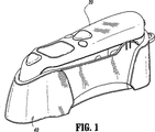
本発明の具体的な実施形態についてここで詳細に説明するが、実施形態は添付の図面に例示されている。ここで全体を通して同一構成要素を同一参照番号で示している図面を参照し、まず、図1および図2を、それから、付記された説明、曲線表示、グラフ、絵を見ると、本発明の原理に従った鼓室体温計20が例示されている。
Reference will now be made in detail to specific embodiments of the invention, examples of which are illustrated in the accompanying drawings. Referring now to the drawings in which like reference numerals refer to like elements throughout, and first referring to FIGS. 1 and 2, then to the accompanying description, curve display, graphs and pictures, the principles of the present invention will be described. A
鼓室体温計20は円筒状の感熱プローブ22を備えている。感熱プローブ22は鼓室体温計20の遠位端24から延び出して、長手方向軸xに沿っている。感熱プローブ22は多様な幾何学的断面形状を有していてもよく、例えば、矩形、長円形などがある。プローブカバー32が遠位端24に取付けられている。プローブカバー32は、具体的には、円錐台形の形状であったり、先細り様式の形にされて、被検体の耳により容易に挿入できるようにするとともに、感熱プローブ22への着脱を容易にできるようにしている。感熱プローブ22は、被検体の鼓膜が放射した赤外線エネルギーを検出するような構成になっている。
The
当業者なら知っていることだが、鼓室体温計20に必要な電子工学系および/または処理部品を設けて、鼓膜を介して温度測定を実施することが思量される。鼓室体温計20は鼓膜の熱エネルギーの検知を容易にするように導波路を設けていてもよい。鼓室体温計20は、使用時のことを考えた格納用のホルダー40に着脱自在に載置される。鼓室体温計20およびホルダー40は半剛性プラスチック、剛性プラスチック、および/または、金属材などの、温度測定および関連用途に好適な材料から作成することができる。ホルダー40は、バッテリー充電能力など、鼓室体温計20の電源補給を促進するのに必要な電子工学系を備えていてもよい。
As one skilled in the art knows, it is contemplated that the
図3を参照すると、プローブカバー32は、フィルム56で実質的に封入される遠位端54を備えている。フィルム56は赤外線放射に対して実質的に透過性があり、感熱プローブ22による赤外線放射の検知を容易にするような構成になっている。フィルム56は耳垢、水分、細菌類などには不透過性であって、病気の伝播を防止するのが好都合である。
With reference to FIG. 3, the
プローブカバーの各構成部分は、使い捨て可能であるが、鼓膜を通して鼓室体温計測定装置で体温測定するのに好適な材料から作成される。このような材料としては、例えば、ポリプロピレン、ポリエチレンなどのプラスチック材料が挙げられるが、これは、特定の温度測定の応用例および/または医師の好み次第で決まる。赤外線放射線に対して実質的に透過性であるとともに水分、耳垢、細菌類などは通さない窓部、または、フィルムがプローブカバーには設けてある。フィルムは厚さが0.0005インチから0.001インチの範囲であるが、これ以外の範囲も思量される。フィルムは半剛性または可撓性であってもよく、また、例えば熱溶着などの方法で、プローブカバーの残余の部分と共にモノリシック成形され、すなわち、同部分に一体接合することができる。しかし、本発明に従った組立ておよび製造に好適な上記以外の材料や製造方法でも適正であると、当業者であれば認識するであろう。 Each component of the probe cover is disposable, but is made from a material suitable for measuring body temperature through the tympanic membrane with a tympanic thermometer measuring device. Such materials include, for example, plastic materials such as polypropylene, polyethylene, etc., depending on the particular temperature measurement application and / or physician preference. The probe cover is provided with a window or film that is substantially transparent to infrared radiation and does not allow moisture, earwax, bacteria, etc. to pass through. Films range from 0.0005 inches to 0.001 inches in thickness, but other ranges are contemplated. The film may be semi-rigid or flexible, and may be monolithically molded with the remaining portion of the probe cover, such as by heat welding, i.e., integrally bonded thereto. However, those skilled in the art will recognize that other materials and methods suitable for assembly and manufacture according to the present invention are also suitable.
図4、図4a、および、図5を参照すると、感熱プローブ22は、ノズル100、感熱電子工学系に装着されたカン102、センサハウジング104、および、ベース部106から構成されている。非限定的な具体例として、ノズル100は、急速な熱交換や熱伝達を助ける金属材などから作成されていればよい。同様に、非限定的な具体例として、センサハウジング104は、プラスチックやそれに類似する他の材料など、ノズル100に比べて低い熱伝導率(すなわち、高い隔絶の程度)に適する材料から作成されているのが好ましい。図4aはノズル100に搭載された場合のプローブカバー32と両者の間に配置された空隙118の部分断面図を開示している。図示のように、ノズル100、センサハウジング104、および、カン102は確実な関係で嵌合し合っている。このような確実な関係は粘着材、摩擦力、圧入などにより確立することができる。空隙118はノズル100とセンサハウジング104との間に配置されている。カン102は、センサベース部126、赤外線センサ122、赤外線フィルターまたは赤外線窓120、サーミスタ124などを更に備えている。
Referring to FIGS. 4, 4 a, and 5, the
感熱プローブ22の構成部品は組み立てられ、ノズル100がその上に取付けられて、遠位方向に設けられたセンサ窓を通して感熱プローブ22の遠位端108に熱束を向けるようにしている。ノズル100は、ベース部110と、細長いノーズ部112とを備え、熱束を遠位端108に伝達するのを容易にする。
The components of the
動作時には、被検体の耳などから発せられる熱がプローブカバー32からノズル100に伝達される。ノズル100はカン102のリップ114と物理的接触していてもよいし、同リップ114と非常に近接した関係であってもよいことが本件では思量される。このような接触によって、ノズル100からカン102のリップ114への熱伝達が可能となる。図6から図9と図11および図12に例示されているように、カン102からリップ114への熱伝達は、どの局在接点、すなわち、どの1個の接点で起こってもよいし(図6から図9および図11および図12はリップ114の上位部分に沿って局在する1個の接点を開示している)、或いは、複数の接点に沿って起こってもよいが、後者の具体例として、リップ114の全長部に沿った複数の点でもよい。
During operation, heat generated from the ear of the subject is transmitted from the
カン102は複数のリップ、隆起部、或いは、それ以外の、爪状部材や結節部材などの類似構造を有していてもよく、これらの補佐でノズル100からカン102への熱伝達が行われ、最終的にはカン先端部116へ伝達される。リップ114は多様な幾何学的形状に形成することもできるが、例えば、螺旋状、短鎖線状などであってもよい。具体例として、リップ114から先端部116までの間の温度勾配を緩和するために(また、内部サーミスタ124(図4a)からカン102の先端部116までの間の温度勾配を緩和するため)、カン102は金属合金などの材料から作成された複数のリップ部材を備えていてもよい。このようなリップ部材は複数の互いに異なる素材から作成されていてもよいし、一部がカン102の本体部と接触していてもよいし、或いは、リップ114からカン先端部116までの間の温度勾配を緩和するように工夫されていてもよい。
The can 102 may have a plurality of lips, protuberances, or other similar structures such as a claw-like member and a knot member, and these assistants transfer heat from the
リップ114によって、或いは、リップ114に追加して、カン102を電気的な方法などで或る所定温度まで予備加熱してもよいことが本件では更に思量される。リップ114がノズル100からの熱伝達を補佐するため、リップ114からカン先端部116までの間の温度勾配が緩和される。カン102のセンサ先端部の2点間でこのように勾配緩和させることで、より迅速かつより高精度の結果を得られるようにしている。
It is further contemplated in this case that the
前段でも述べたが、感熱先端部を隔絶するように設計された先行技術の温度検知用の先端部とは異なり、本発明の鼓室体温計は、先端部116の2点間にかかる温度勾配を緩和するために、リップ114(ノズル100から熱を受ける)からの熱伝達によりセンサ先端部(カン102)を加熱する。
As described earlier, unlike the prior art temperature sensing tip designed to isolate the thermal tip, the tympanic thermometer of the present invention alleviates the temperature gradient between the two points on the
前段で説明するとともに図4、図4a、図5にも例示したように、センサカン102はセンサハウジング104およびノズル100に沿って遠位方向に取付けられている。このような関係によって、センサは温度読取り中に被検体の耳の中、または、実質的に耳に近接して収容される。先行技術はセンサと耳とのこの種の関係を開示してはいるものの、先行技術の関係はセンサの特有の互いに異なる加熱処理上の問題点に関与するものである。後段で論じるとともに図6から図12に例示するように、先行技術の個々に異なる加熱処理上の諸問題点は克服される。
As described above and illustrated in FIGS. 4, 4 a, and 5, the sensor can 102 is attached along the
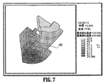
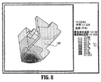
非限定的な具体例として図6から図12を参照すると、鼓室体温計20の一実施形態はプローブカバー32の外表面に40℃の温度負荷が付与された場合の初期温度が20℃である感熱プローブ22を備えている。これは感熱プローブ22を室温から取り出して発熱した人間の被検体の耳の中に入れるのに似ている。図示したように、放熱効果はセンサハウジング104の上面およびノズル100に供与される。センサ接点部を設けたアルミ製ノズル設計について、10秒間、過渡分析を実施した。
Referring to FIGS. 6 to 12 as non-limiting specific examples, one embodiment of the
図6から図12は人間の耳のシミュレーションによる温度読取り試験から得られた等温線を例示している。このようなデータは被検体の耳に関して実施された実際の実験テストに基づいて確認された。図6は、受熱開始1.072秒後のカン102のセンサ部分の2点間にかかる温度分布の等温線を例示している。注目すべき領域としては、吸熱装置チップとサーミスタ124(図4a)が配置されている表面と、センサの内側頂部と、センサカンの内側側面部とがある。図7は、受熱開始3.945秒後のセンサ部分の温度分布の等温線を示している。図8は、受熱開始7.229秒後のセンサ部分の温度分布の等温線を示している。図9は、受熱開始10秒後のセンサ部分の温度分布の等温線を示している。図10は、10秒の時間推移の間の温度分布の平面グラフを示している。頂部とカン102の内側位サーミスタ124(図4a)で実施した接続点解析の結果に基づいて図示したように、カンの2点間の温度差ΔTは10秒の時間推移にわたって実質的に一定である(すなわち、ΔTは本質的にサーミスタ124(図4a)に追従している)。このように、温度精度の誤差が従来技術の体温計のように経時的に増大するということがない。温度の読取りは、図10の平面グラフに沿った実質的にどの点で起こってもかまわないことになる。図11は、受熱開始1.072秒後の、熱束の温度勾配の等温線を示している。図12は、受熱開始10秒後の、熱束の温度勾配の等温線を示している。
6 to 12 illustrate isotherms obtained from a temperature reading test by simulation of the human ear. Such data was confirmed based on actual experimental tests performed on the subject's ears. FIG. 6 illustrates an isotherm of a temperature distribution between two points of the sensor portion of the
本件開示の実施形態に対する多様な修正を行うことができることが分かる。よって、上記説明は制限的であると見なされるべきではなく、多様な実施形態の具体例にすぎないと解釈するべきである。当業者であれば、本明細書に添付した特許請求の範囲の各請求項の範囲と精神から逸脱することなく、上記以外にも多数の修正案を思い描くことができるだろう。 It can be seen that various modifications can be made to the embodiments of the present disclosure. Therefore, the above description should not be construed as limiting, but merely as exemplifications of various embodiments. Those skilled in the art will envision many other modifications other than those described above without departing from the scope and spirit of the claims appended hereto.
Claims (15)
体温計本体部と、
体温計本体部から延び出ている感熱プローブとを備えており、
前記感熱プローブは、
内表面が空洞を画定している、細長い熱伝導性のノズルと、
前記空洞内に配置されて、センサハウジングを前記内表面から分離している空隙を有する細長い断熱材料で出来た断熱用のセンサハウジングと、
断熱材料で出来た前記断熱用センサハウジングの遠位端に直接接触して取付けられて、前記熱伝導性ノズルの前記内表面に接触しているか近接しているセンサカンとを含むことを特徴とする鼓室体温計。A tympanic thermometer,
A thermometer body,
And a thermosensitive probe extending from the thermometer body,
The thermal probe is
An elongated thermally conductive nozzle having an inner surface defining a cavity;
A sensor housing for thermal insulation made of an elongated thermal insulation material disposed in the cavity and having a gap separating the sensor housing from the inner surface;
A sensor can mounted in direct contact with a distal end of the thermal insulation sensor housing made of thermal insulation material and in contact with or in close proximity to the inner surface of the thermally conductive nozzle; Tympanic thermometer.
前記センサカンに設けた少なくとも1個の赤外線透過性窓と、
遠位面を有するセンサベース部と、
前記遠位面に配置されて、前記赤外線透過性窓を通して赤外線放射を受ける赤外線センサとを組込んでいる請求項1に記載の鼓室体温計。The sensor can
At least one infrared transmitting window provided in the sensor can;
A sensor base having a distal surface;
The distally disposed surface, tympanic thermometer according to claim 1 incorporating an infrared sensor for receiving infrared radiation through said infrared transparent window.
カン表面と、前記センサカンに組込まれたサーミスタとを備え、
雰囲気温度が経時的に変動している間も、前記カン表面と前記サーミスタの間の温度差が実質的に一定のままである請求項1に記載の鼓室体温計。The sensor can
A can surface and a thermistor incorporated in the sensor can;
The tympanic thermometer according to claim 1 , wherein the temperature difference between the can surface and the thermistor remains substantially constant while the atmospheric temperature varies with time.
Applications Claiming Priority (2)
| Application Number | Priority Date | Filing Date | Title |
|---|---|---|---|
| US43290402P | 2002-12-12 | 2002-12-12 | |
| PCT/US2003/011606 WO2004055488A1 (en) | 2002-12-12 | 2003-04-15 | Thermal tympanic thermometer tip |
Publications (3)
| Publication Number | Publication Date |
|---|---|
| JP2006509576A JP2006509576A (en) | 2006-03-23 |
| JP2006509576A5 JP2006509576A5 (en) | 2006-06-15 |
| JP4409441B2 true JP4409441B2 (en) | 2010-02-03 |
Family
ID=32595095
Family Applications (1)
| Application Number | Title | Priority Date | Filing Date |
|---|---|---|---|
| JP2004560260A Expired - Fee Related JP4409441B2 (en) | 2002-12-12 | 2003-04-15 | Thermal tympanic thermometer tip |
Country Status (18)
| Country | Link |
|---|---|
| US (3) | US7108419B2 (en) |
| EP (2) | EP1570246B1 (en) |
| JP (1) | JP4409441B2 (en) |
| KR (1) | KR20050085499A (en) |
| CN (1) | CN100488445C (en) |
| AT (2) | ATE421082T1 (en) |
| AU (1) | AU2003224980B2 (en) |
| BR (1) | BR0317262A (en) |
| CA (1) | CA2509033C (en) |
| DE (1) | DE60325891D1 (en) |
| DK (1) | DK1570246T3 (en) |
| ES (2) | ES2319275T3 (en) |
| HK (1) | HK1074076A1 (en) |
| IL (1) | IL181374A (en) |
| MX (1) | MXPA05006157A (en) |
| NO (1) | NO20053382L (en) |
| PT (1) | PT1570246E (en) |
| WO (1) | WO2004055488A1 (en) |
Families Citing this family (46)
| Publication number | Priority date | Publication date | Assignee | Title |
|---|---|---|---|---|
| JP3675230B2 (en) * | 1999-06-11 | 2005-07-27 | オムロンヘルスケア株式会社 | Ear thermometer |
| US7434991B2 (en) * | 2002-12-12 | 2008-10-14 | Covidien Ag | Thermal tympanic thermometer |
| WO2004055488A1 (en) | 2002-12-12 | 2004-07-01 | Sherwood Services Ag | Thermal tympanic thermometer tip |
| US20060120432A1 (en) * | 2003-01-06 | 2006-06-08 | Loren Lantz | Tympanic thermometer with ejection mechanism |
| US7478946B2 (en) * | 2003-01-06 | 2009-01-20 | Covidien Ag | Probe cover cassette with improved probe cover support |
| US7354194B2 (en) | 2003-01-06 | 2008-04-08 | Covidien Ag | Tympanic thermometer probe cover with film support mechanism |
| DE60315895T2 (en) * | 2003-01-06 | 2008-05-29 | Covidien Ag | PROBE COVER FOR DRUM FILL THERMOMETER |
| US20050228307A1 (en) * | 2004-04-13 | 2005-10-13 | Steve Gibree | Removable medical device adapter |
| US20060050769A1 (en) * | 2004-09-08 | 2006-03-09 | Yung-Ku Lee | Waterproof infrared ear thermometer |
| US7083330B1 (en) * | 2004-10-19 | 2006-08-01 | Huang Hua Co., Ltd. | Ear thermometer having breakable ear cap |
| TW200615520A (en) * | 2004-11-09 | 2006-05-16 | Norm Pacific Automat Corp | Infrared thermometer |
| US7857507B2 (en) * | 2004-11-16 | 2010-12-28 | Welch Allyn, Inc. | Temperature patch and method of using the same |
| US7815367B2 (en) * | 2004-11-16 | 2010-10-19 | Welch Allyn, Inc. | Multi-site infrared thermometer |
| US7275867B2 (en) * | 2005-12-01 | 2007-10-02 | Oriental System Technology Inc. | Probe assembly of infrared thermometer |
| US20070248141A1 (en) | 2006-04-21 | 2007-10-25 | Sherwood Services Ag | Infrared thermometer and probe cover thereof |
| TWI280356B (en) * | 2006-05-09 | 2007-05-01 | Radiant Innovation Inc | Ear cap of ear thermometer |
| US7507019B2 (en) | 2006-05-19 | 2009-03-24 | Covidien Ag | Thermometer calibration |
| US7549792B2 (en) | 2006-10-06 | 2009-06-23 | Covidien Ag | Electronic thermometer with selectable modes |
| US7824102B2 (en) * | 2006-12-09 | 2010-11-02 | Shenzhen Mindray Bio-Medical Electronics, Inc. | Thermometer quick linkage apparatus and method |
| US8652040B2 (en) | 2006-12-19 | 2014-02-18 | Valencell, Inc. | Telemetric apparatus for health and environmental monitoring |
| US8308353B2 (en) * | 2007-03-26 | 2012-11-13 | Terumo Kabushiki Kaisha | Ear thermometer and method of manufacturing ear thermometer |
| TW200841859A (en) * | 2007-04-27 | 2008-11-01 | Actherm Inc | Infrared thermometer |
| WO2008153103A1 (en) * | 2007-06-12 | 2008-12-18 | Bio Echo Net Inc | Ear thermometer and measurement device body used for the same |
| US8100886B2 (en) * | 2007-08-15 | 2012-01-24 | Visiomed Group Sa | Aspirator assembly |
| US20090076441A1 (en) * | 2007-08-15 | 2009-03-19 | Eric Sebban | Aspirator assembly |
| US20130096437A1 (en) * | 2007-08-21 | 2013-04-18 | Radiant Innovation Inc. | Method for detecting temple hot spot temperature of a live body |
| US20090074027A1 (en) * | 2007-09-18 | 2009-03-19 | Vatell Corporation | Heat flux sensor incorporating light conveyance |
| TWI340822B (en) * | 2007-11-15 | 2011-04-21 | Actherm Inc | Probe cover for an ear thermometer, manufacturing method thereof |
| US8303177B2 (en) * | 2008-03-31 | 2012-11-06 | Hsueh-Yu Lu | Pre-heat type clinical thermometer |
| US8192075B2 (en) * | 2008-08-19 | 2012-06-05 | Ge Inspection Technologies, Lp | Method for performing ultrasonic testing |
| USD787683S1 (en) | 2009-04-09 | 2017-05-23 | Welch Allyn, Inc. | Cover for a probe |
| US8876373B2 (en) | 2009-04-09 | 2014-11-04 | Welch Allyn, Inc. | IR thermometry probe cover |
| US8231271B2 (en) * | 2009-04-09 | 2012-07-31 | Welch Allyn, Inc. | IR thermometry probe cover |
| US8186876B2 (en) * | 2009-04-20 | 2012-05-29 | Welch Allyn, Inc. | Calibrated assembly for IR thermometer apparatus |
| WO2011044047A1 (en) * | 2009-10-05 | 2011-04-14 | Kaz Europe Sa | Multi-site attachments for ear thermometers |
| US8657758B2 (en) | 2010-12-02 | 2014-02-25 | Welch Allyn, Inc. | Devices and methods for temperature determination |
| JP2013013540A (en) * | 2011-07-04 | 2013-01-24 | Sony Corp | Auricle-installed apparatus |
| JP2013202260A (en) * | 2012-03-29 | 2013-10-07 | Sony Corp | Information processing apparatus, method for processing information, and computer program |
| DE102012223691A1 (en) * | 2012-12-19 | 2014-06-26 | Heine Optotechnik Gmbh & Co Kg | Otoscope with disposable ear funnel |
| CN103284698A (en) * | 2013-05-13 | 2013-09-11 | 曾建新 | Miniature rapid body temperature sensing device |
| US20150317909A1 (en) * | 2014-04-30 | 2015-11-05 | Peter Florkoski | Apparatus and method of simulating a thermometer |
| JP7239150B2 (en) * | 2018-12-14 | 2023-03-14 | 株式会社バイオエコーネット | ear thermometer |
| CN210089862U (en) * | 2019-07-11 | 2020-02-18 | 深圳市福瑞诺科技有限公司 | Dual-purpose infrared ear thermometer easy to clean |
| JP7031646B2 (en) * | 2019-09-24 | 2022-03-08 | カシオ計算機株式会社 | Detection device and manufacturing method of detection device |
| WO2021234986A1 (en) * | 2020-05-19 | 2021-11-25 | 拓則 島崎 | Physical condition change detection device and physical condition change management system |
| WO2024151677A1 (en) * | 2023-01-10 | 2024-07-18 | Cue Health Inc. | Temperature measurement system |
Family Cites Families (155)
| Publication number | Priority date | Publication date | Assignee | Title |
|---|---|---|---|---|
| US3491596A (en) * | 1967-10-02 | 1970-01-27 | Vito Charles P De | Temperature sensing device |
| US3738173A (en) * | 1971-11-22 | 1973-06-12 | Ivac Corp | Temperature sensing probe and disposable probe cover |
| US4005605A (en) * | 1974-07-22 | 1977-02-01 | Mikron Instrument Company, Inc. | Remote reading infrared thermometer |
| US4346427A (en) * | 1979-06-29 | 1982-08-24 | Robert Rothenhaus | Control device responsive to infrared radiation |
| WO1981000764A1 (en) * | 1979-09-12 | 1981-03-19 | M Jacobs | Hand-held digital temperature measuring instrument |
| US4343182A (en) * | 1980-07-14 | 1982-08-10 | Exergen Corporation | Radiation heat loss detector |
| US4456390A (en) * | 1981-10-26 | 1984-06-26 | Wahl Instruments, Inc. | Noncontact temperature measuring device |
| US4527896A (en) * | 1982-03-04 | 1985-07-09 | Mikron Instrument Company, Inc. | Infrared transducer-transmitter for non-contact temperature measurement |
| US4566808A (en) * | 1983-02-16 | 1986-01-28 | Exergen Corporation | Scanning radiation detector |
| JPS6054070A (en) | 1983-09-02 | 1985-03-28 | Nec Corp | Arithmetic unit |
| US4626686A (en) * | 1984-04-09 | 1986-12-02 | Exergen Corporation | Variable field of view heat scanner |
| US4662360A (en) | 1984-10-23 | 1987-05-05 | Intelligent Medical Systems, Inc. | Disposable speculum |
| US4790324A (en) * | 1984-10-23 | 1988-12-13 | Intelligent Medical Systems, Inc. | Method and apparatus for measuring internal body temperature utilizing infrared emissions |
| US5179936A (en) * | 1984-10-23 | 1993-01-19 | Intelligent Medical Systems, Inc. | Disposable speculum with membrane bonding ring |
| US4602642A (en) * | 1984-10-23 | 1986-07-29 | Intelligent Medical Systems, Inc. | Method and apparatus for measuring internal body temperature utilizing infrared emissions |
| US4588306A (en) * | 1985-03-22 | 1986-05-13 | Chesebrough-Pond's Inc. | Electronic thermometer probe assembly |
| DE3650770T2 (en) * | 1985-04-17 | 2003-02-27 | Thermoscan Inc., San Diego | Electronic infrared thermometer and method for temperature measurement |
| US4682898A (en) * | 1985-06-06 | 1987-07-28 | Honeywell Inc. | Method and apparatus for measuring a varying parameter |
| US4636091A (en) * | 1985-06-27 | 1987-01-13 | Exergen Corporation | Radiation detector having temperature readout |
| US4722612A (en) * | 1985-09-04 | 1988-02-02 | Wahl Instruments, Inc. | Infrared thermometers for minimizing errors associated with ambient temperature transients |
| US4784149A (en) * | 1986-01-13 | 1988-11-15 | Optical Sensors, Inc. | Infrared thermometer with automatic calibration |
| US4874253A (en) * | 1987-03-27 | 1989-10-17 | Exergen Corporation | Radiation detector with temperature display |
| US4854730A (en) * | 1987-08-13 | 1989-08-08 | Jacob Fraden | Radiation thermometer and method for measuring temperature |
| WO1989006348A1 (en) * | 1987-12-25 | 1989-07-13 | Nippon Steel Corporation | Optical thermometer |
| US4896039A (en) * | 1987-12-31 | 1990-01-23 | Jacob Fraden | Active infrared motion detector and method for detecting movement |
| US4831258A (en) * | 1988-03-04 | 1989-05-16 | Exergen Corporation | Dual sensor radiation detector |
| JP2826337B2 (en) * | 1988-04-12 | 1998-11-18 | シチズン時計株式会社 | Radiation thermometer |
| US4867574A (en) * | 1988-05-19 | 1989-09-19 | Jenkofsky John J | Ultra high speed infrared temperature measuring device |
| US4895164A (en) * | 1988-09-15 | 1990-01-23 | Telatemp Corp. | Infrared clinical thermometer |
| US4911559A (en) * | 1988-11-01 | 1990-03-27 | Diatek, Inc. | Disposable probe cover assembly for medical thermometer |
| US5018872A (en) | 1988-11-01 | 1991-05-28 | Diatek, Inc. | Probe assembly for infrared thermometer |
| US5325863A (en) * | 1988-12-06 | 1994-07-05 | Exergen Corporation | Radiation detector with high thermal stability |
| US5199436A (en) * | 1988-12-06 | 1993-04-06 | Exergen Corporation | Radiation detector having improved accuracy |
| US5445158A (en) * | 1988-12-06 | 1995-08-29 | Exergen Corporation | Radiation detector probe |
| US5012813A (en) * | 1988-12-06 | 1991-05-07 | Exergen Corporation | Radiation detector having improved accuracy |
| US5271407A (en) * | 1988-12-06 | 1993-12-21 | Exergen Corporation | Radiation detector suitable for tympanic temperature measurement |
| US4993419A (en) * | 1988-12-06 | 1991-02-19 | Exergen Corporation | Radiation detector suitable for tympanic temperature measurement |
| US5381796A (en) * | 1992-05-22 | 1995-01-17 | Exergen Corporation | Ear thermometer radiation detector |
| US6219573B1 (en) * | 1989-04-14 | 2001-04-17 | Exergen Corporation | Radiation detector probe |
| US4900162A (en) * | 1989-03-20 | 1990-02-13 | Ivac Corporation | Infrared thermometry system and method |
| US5019804A (en) * | 1989-04-10 | 1991-05-28 | Jacob Fraden | Apparatus and method for detecting movement of an object |
| US5017019A (en) * | 1989-04-14 | 1991-05-21 | Exergen Corporation | Radiation detector for differential biological temperature readings |
| US5163418A (en) * | 1989-09-19 | 1992-11-17 | Thermoscan Inc. | Speculum cover |
| US5054936A (en) * | 1989-11-16 | 1991-10-08 | Jacob Fraden | Sensor for active thermal detection |
| US4993424A (en) * | 1989-12-04 | 1991-02-19 | Diatek, Incorporated | Infrared medical thermometer |
| DE69132890T2 (en) * | 1990-03-08 | 2002-08-29 | Alaris Medical Systems, Inc. | Thermally insulated probe |
| US5066142A (en) * | 1990-03-08 | 1991-11-19 | Ivac Corporation | Protective apparatus for a biomedical probe |
| US5150969A (en) * | 1990-03-12 | 1992-09-29 | Ivac Corporation | System and method for temperature determination and calibration in a biomedical probe |
| US5081359A (en) * | 1990-05-23 | 1992-01-14 | Exergen Corporation | Differential thermal sensor |
| US5229612B1 (en) * | 1990-08-01 | 1998-04-14 | Exergen Corp | Radiation detector with remote temperature reference |
| EP0541697B2 (en) * | 1990-08-01 | 2001-12-05 | Exergen Corporation | Radiation detector with remote temperature reference |
| US5159936A (en) * | 1990-08-17 | 1992-11-03 | Mark Yelderman | Noncontact infrared tympanic thermometer |
| US5088834A (en) * | 1990-08-24 | 1992-02-18 | Thermoscan Inc. | Unitary probe cover |
| US5119436A (en) * | 1990-09-24 | 1992-06-02 | Kulicke And Soffa Industries, Inc | Method of centering bond positions |
| BR9107167A (en) * | 1990-12-12 | 1994-02-22 | Sherwood Ims Inc | BODY TEMPERATURE THERMOMETER AND METHOD OF MEASURING HUMAN BODY TEMPERATURE USING A CALIBRATION MAPPING |
| JP3179788B2 (en) * | 1991-01-17 | 2001-06-25 | 三菱電機株式会社 | Semiconductor storage device |
| US5469855A (en) * | 1991-03-08 | 1995-11-28 | Exergen Corporation | Continuous temperature monitor |
| US5127742A (en) * | 1991-04-19 | 1992-07-07 | Thermoscan Inc. | Apparatus and method for temperature measurement by radiation |
| US5178464A (en) * | 1991-04-19 | 1993-01-12 | Thermoscan Inc. | Balance infrared thermometer and method for measuring temperature |
| US5183337A (en) * | 1991-07-08 | 1993-02-02 | Exergen Corporation | Thermometer calibration |
| US5333784A (en) * | 1993-03-02 | 1994-08-02 | Exergen Corporation | Radiation detector with thermocouple calibration and remote temperature reference |
| US5368038A (en) * | 1993-03-08 | 1994-11-29 | Thermoscan Inc. | Optical system for an infrared thermometer |
| US5411032A (en) * | 1993-06-18 | 1995-05-02 | Infra-Temp Inc. | Electronic thermometer probe cover |
| DE4331574C2 (en) * | 1993-09-16 | 1997-07-10 | Heimann Optoelectronics Gmbh | Infrared sensor module |
| US20030185273A1 (en) | 1993-09-17 | 2003-10-02 | Hollander Milton Bernard | Laser directed temperature measurement |
| US5645349A (en) * | 1994-01-10 | 1997-07-08 | Thermoscan Inc. | Noncontact active temperature sensor |
| US5646349A (en) * | 1994-02-18 | 1997-07-08 | Plan B Enterprises, Inc. | Floating mass accelerometer |
| CN1168623A (en) | 1994-02-28 | 1997-12-24 | 伊康诺梅逊公司 | Infrared tympanic thermometer |
| IT1272219B (en) * | 1994-04-27 | 1997-06-16 | Siv Soc Italiana Vetro | APPARATUS FOR THE CONTROL OF AN ELECTROCHROMIC WINDOW |
| US5626139A (en) * | 1994-09-23 | 1997-05-06 | Artech Industries, Inc. | Tympanic thermometer |
| EP0861425A1 (en) * | 1995-11-18 | 1998-09-02 | Braun Aktiengesellschaft | Process for evaluating the signal of an infrared thermometer, and infrared thermometer |
| DE19543096C2 (en) * | 1995-11-18 | 1998-07-23 | Braun Ag | Infrared radiation thermometer |
| WO1997024588A1 (en) * | 1995-12-28 | 1997-07-10 | Omron Corporation | Infrared thermometer |
| DE19604201A1 (en) * | 1996-02-06 | 1997-08-07 | Braun Ag | protective cap |
| US5820264A (en) * | 1996-03-25 | 1998-10-13 | Oriental System Technology, Inc. | Tympanic thermometer arrangement |
| US5645350A (en) * | 1996-04-12 | 1997-07-08 | Jang; Chen-Chang | Hygienic protecting device for an electronic thermometer |
| US6179785B1 (en) * | 1996-10-17 | 2001-01-30 | Sherwood Services, Ag | Ambient sensing feature for thermometer recalibration system |
| US5874736A (en) * | 1996-10-25 | 1999-02-23 | Exergen Corporation | Axillary infrared thermometer and method of use |
| FR2773213B1 (en) | 1996-12-11 | 2001-08-24 | Omega Engineering | METHOD AND DEVICE FOR INFRARED MEASUREMENT OF THE SURFACE TEMPERATURE |
| WO1998055841A2 (en) * | 1997-06-03 | 1998-12-10 | Trutek Inc. | Tympanic thermometer with modular sensing probe |
| EP1304555B1 (en) * | 1997-07-16 | 2007-05-23 | Terumo Kabushiki Kaisha | Ear type clinical thermometer |
| JPH1147098A (en) * | 1997-08-08 | 1999-02-23 | Omron Corp | Radial thermometer |
| JP4018782B2 (en) * | 1997-09-10 | 2007-12-05 | シチズンホールディングス株式会社 | Radiation thermometer |
| DE19757447A1 (en) * | 1997-12-23 | 1999-07-01 | Braun Gmbh | Temperature calculation method for radiation thermometers |
| US6129673A (en) * | 1998-06-08 | 2000-10-10 | Advanced Monitors, Corp. | Infrared thermometer |
| US6224256B1 (en) * | 1998-06-18 | 2001-05-01 | Harry Bala | Cover for medical probe |
| US6292685B1 (en) * | 1998-09-11 | 2001-09-18 | Exergen Corporation | Temporal artery temperature detector |
| IL126224A0 (en) * | 1998-09-15 | 1999-05-09 | Gerlitz Jonathan | Ear thermometer and detector therefor |
| CN1147717C (en) * | 1998-09-16 | 2004-04-28 | 布劳恩有限公司 | Method for determining tmep. radiation thermometer with several infrared sensor elements |
| JP3514138B2 (en) | 1998-09-29 | 2004-03-31 | テルモ株式会社 | Probe cover removal mechanism and ear thermometer |
| DE69934508T2 (en) | 1998-10-20 | 2007-09-27 | Omron Healthcare Co., Ltd. | INFRARED THERMOMETER |
| DE29819056U1 (en) | 1998-10-26 | 1999-02-25 | Chen, Chao-Wang, Taipeh/T'ai-pei | Infrared thermometer |
| US6572264B1 (en) * | 1998-12-15 | 2003-06-03 | Citizen Watch Co., Ltd. | Radiation clinical thermometer |
| DE29902276U1 (en) * | 1999-02-09 | 1999-04-15 | Chen, Chao-Wang, Taipeh/T'ai-pei | Infrared sensor for a thermometer |
| US6139182A (en) * | 1999-03-01 | 2000-10-31 | Thermoscan, Inc | Enhanced protective cover for use in an IR thermometer |
| DE19913672A1 (en) | 1999-03-25 | 2000-11-02 | Braun Gmbh | Infrared thermometer with a heatable measuring tip and protective cap |
| DE29907098U1 (en) | 1999-04-21 | 1999-07-22 | Chen, Chao-Wang, Taipeh/T'ai-pei | Test head for an infrared thermometer |
| US6901089B1 (en) * | 1999-07-02 | 2005-05-31 | Milton Bernard Hollander | Laser instrument |
| DE19942214A1 (en) * | 1999-09-03 | 2001-03-08 | Braun Gmbh | Heated infrared sensor and infrared thermometer with such a sensor |
| USD464555S1 (en) * | 1999-10-28 | 2002-10-22 | The Eastern Company | Portions of a clamp bracket assembly for use with push button latch and lock operating assemblies |
| US6983753B1 (en) * | 1999-11-17 | 2006-01-10 | Smithkline Beecham Corporation | Infrared thermography |
| US6319206B1 (en) | 1999-11-24 | 2001-11-20 | Exergen Corporation | Temporal thermometer disposable cap |
| US6227256B1 (en) * | 1999-12-13 | 2001-05-08 | Albany International Corp. | Multi-layer papermaking fabric having long weft floats on its support and machine surfaces |
| GB0005926D0 (en) | 2000-03-10 | 2000-05-03 | Univ Glasgow | Microwave radiometry |
| US6390671B1 (en) * | 2000-04-28 | 2002-05-21 | K-Jump Health Co., Ltd. | Probe cover with film insert |
| IT1317648B1 (en) * | 2000-05-19 | 2003-07-15 | Tecnica S R L | PERFECTED INFRARED THERMOMETER |
| DE10025157A1 (en) * | 2000-05-23 | 2001-11-29 | Braun Gmbh | Infrared radiation thermometer with changeable measuring tip |
| JP3690387B2 (en) * | 2000-06-13 | 2005-08-31 | オムロンヘルスケア株式会社 | Radiation thermometer |
| TW437956U (en) * | 2000-09-15 | 2001-05-28 | Peng Shau Yu | Ear thermometer with rotating-type probing head |
| US7014358B2 (en) * | 2001-02-19 | 2006-03-21 | Braun Gmbh | Radiation thermometer comprising a heated measuring tip |
| EP1239271A1 (en) | 2001-03-07 | 2002-09-11 | Microlife Intellectual Property GmbH | An infrared medical thermometer |
| EP1249691A1 (en) * | 2001-04-11 | 2002-10-16 | Omron Corporation | Electronic clinical thermometer |
| JP2002345761A (en) * | 2001-05-22 | 2002-12-03 | Omron Corp | Infrared thermometer probe |
| KR100363284B1 (en) * | 2001-05-22 | 2002-12-11 | 주식회사 메타텍 | An Infrared Thermometer |
| JP3945189B2 (en) * | 2001-06-01 | 2007-07-18 | オムロンヘルスケア株式会社 | Infrared thermometer |
| JP3900865B2 (en) * | 2001-06-04 | 2007-04-04 | オムロンヘルスケア株式会社 | Infrared thermometer, infrared thermometer temperature state estimation method, information notification method, and measurement operation management method |
| US6637931B2 (en) * | 2001-07-19 | 2003-10-28 | Oriental System Technology Inc. | Probe for use in an infrared thermometer |
| US20030067958A1 (en) * | 2001-10-09 | 2003-04-10 | Chen-Chang Jang | Infrared thermometer as measured on forehead artery area |
| US6749334B2 (en) * | 2002-08-09 | 2004-06-15 | Radiant Innovation Inc. | Ear thermometer probe structure |
| US20040047392A1 (en) * | 2002-09-06 | 2004-03-11 | Shu-Mei Wu | Apparatus for measuring ear and forehead temperature |
| US6979121B2 (en) | 2002-10-18 | 2005-12-27 | Mesure Technology, Co., Ltd. | Temperature probe and thermometer having the same |
| TW567054B (en) | 2002-11-28 | 2003-12-21 | Actherm Inc | Method for assembling electric clinical thermometer and structure thereof |
| US6981796B2 (en) * | 2002-12-04 | 2006-01-03 | Actherm Inc. | Electronic thermometer |
| JP2004191075A (en) | 2002-12-06 | 2004-07-08 | Matsushita Electric Ind Co Ltd | Temperature measuring device, temperature correction method, and image formation device |
| WO2004055488A1 (en) | 2002-12-12 | 2004-07-01 | Sherwood Services Ag | Thermal tympanic thermometer tip |
| US6950028B2 (en) | 2003-04-25 | 2005-09-27 | Stephen Eliot Zweig | Electronic time-temperature indicator |
| US6886979B2 (en) * | 2003-05-23 | 2005-05-03 | Carl J Conforti | Temperature measure device |
| US7374336B2 (en) * | 2003-06-16 | 2008-05-20 | Jacob Fraden | Contact thermometer for body cavity |
| TWM266444U (en) | 2003-08-29 | 2005-06-01 | Mesure Technology Co Ltd | Foldable sensing head and its clinical thermometer |
| DE10341433A1 (en) * | 2003-09-09 | 2005-03-31 | Braun Gmbh | Heatable infrared sensor and infrared thermometer with such an infrared sensor |
| US20050085733A1 (en) * | 2003-10-17 | 2005-04-21 | Anthony Wong | Ear thermometer illumination system |
| US20050083991A1 (en) * | 2003-10-17 | 2005-04-21 | Anthony Wong | Probe cover storage system for ear thermometer |
| US7021824B2 (en) * | 2003-10-20 | 2006-04-04 | Welch Allyn, Inc. | Switch assembly for thermometry apparatus |
| TWM244878U (en) | 2003-10-21 | 2004-10-01 | Innovatech Inc | Electric ear thermometer capable of storing a number of people's data |
| TW593993B (en) * | 2003-11-03 | 2004-06-21 | Oriental System Technology Inc | Electrical thermometer |
| EP1530034A1 (en) * | 2003-11-05 | 2005-05-11 | Microlife Intellectual Property GmbH | An infrared thermometer and a method for determining a temperature |
| US20050157775A1 (en) * | 2003-11-17 | 2005-07-21 | Maverick Industries, Inc. | Temperature probe and use thereof |
| US7611278B2 (en) * | 2003-12-02 | 2009-11-03 | White Box, Inc. | Infrared thermometers |
| US20050207470A1 (en) | 2004-01-26 | 2005-09-22 | Bennett Timothy J | Focusing thermometer |
| TWM251738U (en) | 2004-01-30 | 2004-12-01 | Yuan Ho Harmony Co Ltd | Infrared temperature sensor |
| US20050209516A1 (en) | 2004-03-22 | 2005-09-22 | Jacob Fraden | Vital signs probe |
| DK1734858T3 (en) | 2004-03-22 | 2014-10-20 | Bodymedia Inc | NON-INVASIVE TEMPERATURE MONITORING DEVICE |
| US20050226307A1 (en) | 2004-04-07 | 2005-10-13 | Sherin Lussier | Infrared thermometer |
| US20050276308A1 (en) | 2004-06-10 | 2005-12-15 | Pint Charles S | Method and apparatus for measuring temperature and emissivity |
| US20060050769A1 (en) * | 2004-09-08 | 2006-03-09 | Yung-Ku Lee | Waterproof infrared ear thermometer |
| TW200615520A (en) * | 2004-11-09 | 2006-05-16 | Norm Pacific Automat Corp | Infrared thermometer |
| JP2005128033A (en) | 2004-12-27 | 2005-05-19 | Omron Healthcare Co Ltd | Radiation thermometer |
| JP2005128031A (en) | 2004-12-27 | 2005-05-19 | Omron Healthcare Co Ltd | Radiation thermometer |
| JP2005128034A (en) | 2004-12-27 | 2005-05-19 | Omron Healthcare Co Ltd | Radiation thermometer |
| JP4148219B2 (en) | 2004-12-27 | 2008-09-10 | オムロンヘルスケア株式会社 | Radiation thermometer |
| US20060153278A1 (en) * | 2005-01-11 | 2006-07-13 | Kun-Sung Chen | Ear thermometer |
| US20060198424A1 (en) * | 2005-03-02 | 2006-09-07 | Kun-Sung Chen | Probe structure for an ear thermometer |
| US20060215728A1 (en) * | 2005-03-28 | 2006-09-28 | Chen-Chang Jang | Forehead thermometer for hygienic measurement |
| US7275867B2 (en) * | 2005-12-01 | 2007-10-02 | Oriental System Technology Inc. | Probe assembly of infrared thermometer |
| US7988352B2 (en) * | 2006-11-01 | 2011-08-02 | Radiant Innovation Inc. | Probe structure |
-
2003
- 2003-04-15 WO PCT/US2003/011606 patent/WO2004055488A1/en active IP Right Grant
- 2003-04-15 US US10/480,428 patent/US7108419B2/en not_active Expired - Lifetime
- 2003-04-15 BR BR0317262-7A patent/BR0317262A/en not_active Application Discontinuation
- 2003-04-15 CN CNB038256126A patent/CN100488445C/en not_active Expired - Fee Related
- 2003-04-15 JP JP2004560260A patent/JP4409441B2/en not_active Expired - Fee Related
- 2003-04-15 DK DK03721680T patent/DK1570246T3/en active
- 2003-04-15 KR KR1020057010504A patent/KR20050085499A/en not_active Application Discontinuation
- 2003-04-15 EP EP03721680A patent/EP1570246B1/en not_active Expired - Lifetime
- 2003-04-15 AT AT03721680T patent/ATE421082T1/en not_active IP Right Cessation
- 2003-04-15 CA CA2509033A patent/CA2509033C/en not_active Expired - Lifetime
- 2003-04-15 PT PT03721680T patent/PT1570246E/en unknown
- 2003-04-15 AU AU2003224980A patent/AU2003224980B2/en not_active Expired
- 2003-04-15 ES ES03721680T patent/ES2319275T3/en not_active Expired - Lifetime
- 2003-04-15 MX MXPA05006157A patent/MXPA05006157A/en active IP Right Grant
- 2003-04-15 AT AT07012177T patent/ATE523770T1/en not_active IP Right Cessation
- 2003-04-15 EP EP07012177A patent/EP1840543B1/en not_active Expired - Lifetime
- 2003-04-15 DE DE60325891T patent/DE60325891D1/en not_active Expired - Lifetime
- 2003-04-15 ES ES07012177T patent/ES2372200T3/en not_active Expired - Lifetime
-
2005
- 2005-05-06 US US11/123,902 patent/US7140764B2/en not_active Expired - Lifetime
- 2005-07-12 NO NO20053382A patent/NO20053382L/en not_active Application Discontinuation
- 2005-09-15 HK HK05108067.6A patent/HK1074076A1/en not_active IP Right Cessation
-
2007
- 2007-02-15 IL IL181374A patent/IL181374A/en not_active IP Right Cessation
-
2008
- 2008-08-08 US US12/188,878 patent/US7841767B2/en not_active Expired - Lifetime
Also Published As
| Publication number | Publication date |
|---|---|
| CN1714283A (en) | 2005-12-28 |
| AU2003224980B2 (en) | 2007-03-15 |
| CN100488445C (en) | 2009-05-20 |
| US20040240516A1 (en) | 2004-12-02 |
| AU2003224980A1 (en) | 2004-07-09 |
| KR20050085499A (en) | 2005-08-29 |
| CA2509033A1 (en) | 2004-07-01 |
| US7108419B2 (en) | 2006-09-19 |
| EP1840543B1 (en) | 2011-09-07 |
| CA2509033C (en) | 2011-10-11 |
| IL181374A0 (en) | 2007-07-04 |
| WO2004055488A1 (en) | 2004-07-01 |
| ATE523770T1 (en) | 2011-09-15 |
| EP1570246B1 (en) | 2009-01-14 |
| NO20053382D0 (en) | 2005-07-12 |
| EP1840543A1 (en) | 2007-10-03 |
| DK1570246T3 (en) | 2009-04-20 |
| BR0317262A (en) | 2005-11-08 |
| ES2319275T3 (en) | 2009-05-06 |
| US7140764B2 (en) | 2006-11-28 |
| IL181374A (en) | 2011-11-30 |
| US20080298429A1 (en) | 2008-12-04 |
| PT1570246E (en) | 2009-04-09 |
| DE60325891D1 (en) | 2009-03-05 |
| MXPA05006157A (en) | 2005-08-26 |
| ATE421082T1 (en) | 2009-01-15 |
| HK1074076A1 (en) | 2005-10-28 |
| EP1570246A1 (en) | 2005-09-07 |
| US20050254549A1 (en) | 2005-11-17 |
| ES2372200T3 (en) | 2012-01-17 |
| US7841767B2 (en) | 2010-11-30 |
| JP2006509576A (en) | 2006-03-23 |
| NO20053382L (en) | 2005-07-12 |
Similar Documents
| Publication | Publication Date | Title |
|---|---|---|
| JP4409441B2 (en) | Thermal tympanic thermometer tip | |
| CA2589420C (en) | Thermal tympanic thermometer | |
| US7520671B2 (en) | Tympanic thermometer probe cover | |
| EP0411121A1 (en) | Optical thermometer | |
| JPH0528617B2 (en) | ||
| AU2007200873B2 (en) | Thermal tympanic thermometer tip |
Legal Events
| Date | Code | Title | Description |
|---|---|---|---|
| A521 | Request for written amendment filed |
Free format text: JAPANESE INTERMEDIATE CODE: A523 Effective date: 20060417 |
|
| A621 | Written request for application examination |
Free format text: JAPANESE INTERMEDIATE CODE: A621 Effective date: 20060417 |
|
| A131 | Notification of reasons for refusal |
Free format text: JAPANESE INTERMEDIATE CODE: A131 Effective date: 20090608 |
|
| A521 | Request for written amendment filed |
Free format text: JAPANESE INTERMEDIATE CODE: A523 Effective date: 20090908 |
|
| TRDD | Decision of grant or rejection written | ||
| A01 | Written decision to grant a patent or to grant a registration (utility model) |
Free format text: JAPANESE INTERMEDIATE CODE: A01 Effective date: 20091026 |
|
| A01 | Written decision to grant a patent or to grant a registration (utility model) |
Free format text: JAPANESE INTERMEDIATE CODE: A01 |
|
| A61 | First payment of annual fees (during grant procedure) |
Free format text: JAPANESE INTERMEDIATE CODE: A61 Effective date: 20091111 |
|
| R150 | Certificate of patent or registration of utility model |
Free format text: JAPANESE INTERMEDIATE CODE: R150 |
|
| FPAY | Renewal fee payment (event date is renewal date of database) |
Free format text: PAYMENT UNTIL: 20121120 Year of fee payment: 3 |
|
| FPAY | Renewal fee payment (event date is renewal date of database) |
Free format text: PAYMENT UNTIL: 20131120 Year of fee payment: 4 |
|
| R250 | Receipt of annual fees |
Free format text: JAPANESE INTERMEDIATE CODE: R250 |
|
| R250 | Receipt of annual fees |
Free format text: JAPANESE INTERMEDIATE CODE: R250 |
|
| R250 | Receipt of annual fees |
Free format text: JAPANESE INTERMEDIATE CODE: R250 |
|
| LAPS | Cancellation because of no payment of annual fees |