JP4409427B2 - Data processing system having multiple register contexts and method for the system - Google Patents
Data processing system having multiple register contexts and method for the system Download PDFInfo
- Publication number
- JP4409427B2 JP4409427B2 JP2004509742A JP2004509742A JP4409427B2 JP 4409427 B2 JP4409427 B2 JP 4409427B2 JP 2004509742 A JP2004509742 A JP 2004509742A JP 2004509742 A JP2004509742 A JP 2004509742A JP 4409427 B2 JP4409427 B2 JP 4409427B2
- Authority
- JP
- Japan
- Prior art keywords
- register
- context
- data processing
- contexts
- processing system
- Prior art date
- Legal status (The legal status is an assumption and is not a legal conclusion. Google has not performed a legal analysis and makes no representation as to the accuracy of the status listed.)
- Expired - Fee Related
Links
Images


Classifications
-
- G—PHYSICS
- G06—COMPUTING OR CALCULATING; COUNTING
- G06F—ELECTRIC DIGITAL DATA PROCESSING
- G06F9/00—Arrangements for program control, e.g. control units
-
- G—PHYSICS
- G06—COMPUTING OR CALCULATING; COUNTING
- G06F—ELECTRIC DIGITAL DATA PROCESSING
- G06F9/00—Arrangements for program control, e.g. control units
- G06F9/06—Arrangements for program control, e.g. control units using stored programs, i.e. using an internal store of processing equipment to receive or retain programs
- G06F9/30—Arrangements for executing machine instructions, e.g. instruction decode
- G06F9/30098—Register arrangements
- G06F9/3012—Organisation of register space, e.g. banked or distributed register file
- G06F9/30123—Organisation of register space, e.g. banked or distributed register file according to context, e.g. thread buffers
-
- G—PHYSICS
- G06—COMPUTING OR CALCULATING; COUNTING
- G06F—ELECTRIC DIGITAL DATA PROCESSING
- G06F12/00—Accessing, addressing or allocating within memory systems or architectures
-
- G—PHYSICS
- G06—COMPUTING OR CALCULATING; COUNTING
- G06F—ELECTRIC DIGITAL DATA PROCESSING
- G06F9/00—Arrangements for program control, e.g. control units
- G06F9/06—Arrangements for program control, e.g. control units using stored programs, i.e. using an internal store of processing equipment to receive or retain programs
- G06F9/30—Arrangements for executing machine instructions, e.g. instruction decode
- G06F9/30098—Register arrangements
- G06F9/3012—Organisation of register space, e.g. banked or distributed register file
- G06F9/30134—Register stacks; shift registers
Landscapes
- Engineering & Computer Science (AREA)
- Theoretical Computer Science (AREA)
- Software Systems (AREA)
- Physics & Mathematics (AREA)
- General Engineering & Computer Science (AREA)
- General Physics & Mathematics (AREA)
- Executing Machine-Instructions (AREA)
Description
本発明は、一般に、データ処理システムに関し、より詳細には、複数のレジスタ・コンテキストを有するデータ処理システムに関する。 The present invention relates generally to data processing systems, and more particularly to data processing systems having multiple register contexts.
マイクロプロセッサなどのデータ処理システムでは、動作の実行および処理を制御するのにプロセッサが利用される。プロセッサは、通常の動作中および例外処理中にプロセッサによって利用されるレジスタ・コンテキストを格納するレジスタ群を含む。割り込み、またはプロセス切り替えが生じた場合、割り込み処理プログラムまたは新たなプロセスが同一のレジスタ群を使用し、レジスタ内の値の一部を変更する可能性があるため、レジスタ・コンテキスト情報が壊れる可能性がある。 In a data processing system such as a microprocessor, a processor is used to control the execution and processing of operations. The processor includes a set of registers that store register contexts utilized by the processor during normal operation and exception handling. If an interrupt or process switch occurs, the register context information may be corrupted because the interrupt handler or new process may use the same registers and change some of the values in the registers There is.
上述の問題の1つの解決法は、割り込みの処理または新たなプロセスを開始するのに先立って、レジスタ・コンテキストの現在の値をメモリの中に保存し、割り込み処理が完了した時点、または現在のプロセスに戻る時点で、メモリからレジスタ群の中に保存されているレジスタ・コンテキスト値を再び読み込むことである。しかし、レジスタ・コンテキストを保存すること、および新たなコンテキストをロードすることのオーバーヘッドは、リアルタイム環境または高性能環境においては望ましくない。したがって、柔軟性があり、オーバーヘッドを減らすデータ処理システムにおけるレジスタ・コンテキスト選択方式の必要性が存在する。 One solution to the above problem is to store the current value of the register context in memory prior to handling the interrupt or starting a new process, either when the interrupt processing is complete, or the current When returning to the process, the register context values stored in the registers are read again from memory. However, the overhead of saving the register context and loading a new context is undesirable in a real-time or high-performance environment. Thus, there is a need for a register context selection scheme in a data processing system that is flexible and reduces overhead.
本発明を、例として、限定としてではなく、添付の図によって示す。図では、同様の符号は同様の要素を示す。
図における諸要素は、簡明にするために示しており、必ずしも原寸に比例して描かれているわけではないことは、当業者には理解されよう。例えば、図における諸要素の一部の寸法は、本発明の諸実施形態の理解を向上させるのに役立つよう、他の諸要素と比べて誇張されている可能性がある。
The invention is illustrated by way of example and not by way of limitation, with reference to the accompanying figures. In the figures, like numerals indicate like elements.
Those skilled in the art will appreciate that the elements in the figures are shown for simplicity and are not necessarily drawn to scale. For example, the dimensions of some of the elements in the figures may be exaggerated compared to other elements to help improve the understanding of embodiments of the invention.
本明細書で使用する「バス」という用語は、データ、アドレス、制御、またはステータスなどの1つまたは複数の様々なタイプの情報を転送するのに使用することが可能な複数の信号または導体を指すのに使用する。「アサートする」および「ネゲートする」(または「デアサートする」)という用語は、信号、ステータス・ビット、または類似の装置を論理的に真の状態、または論理的に偽の状態にすることを指す場合にそれぞれ使用される。論理的に真の状態が論理レベル1である場合、論理的に偽の状態は論理レベル0である。また、論理的に真の状態が論理レベル0である場合、論理的に偽の状態は論理レベル1である。数の前に付いた記号「$」は、その数が16進形式で、つまり16を基数とする形式で表されていることを示す。数の前に付いた記号「%」は、その数が2進形式、つまり2を基数とする形式で表されていることを示す。
As used herein, the term “bus” refers to a plurality of signals or conductors that can be used to transfer one or more various types of information, such as data, address, control, or status. Used to point. The terms “assert” and “negate” (or “deassert”) refer to putting a signal, status bit, or similar device into a logically true state or a logically false state. Used in each case. If the logically true state is
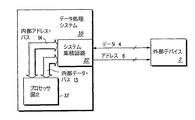
図1は、データ・バス4およびアドレス・バス6を介して外部デバイス2に結合されたデータ処理システム10を示している。データ処理システム10は、プロセッサ12を含む。一実施形態では、データ処理システム10および外部デバイス2はそれぞれ、別々の集積回路として実装される。代替の実施形態では、データ処理システム10および外部デバイス2は、単一の集積回路上に実装することが可能である。データ処理システム10内部では、プロセッサ12が、内部データ・バス13および内部アドレス・バス14でシス
テム集積回路22に結合される。
FIG. 1 shows a
本発明の一部の実施形態では、データ処理システム10は、単一の集積回路上に形成されることに留意されたい。さらに、一部の実施形態では、データ処理システム10は、シングル・チップ・マイクロコントローラ、マイクロプロセッサ、デジタル信号プロセッサ、または他の任意のタイプのデータ処理システムであることが可能である。さらに、データ処理システム10は、任意のタイプの電気回路を使用して実装することが可能である。外部デバイス2は、メモリまたは任意のタイプの周辺デバイスを含め、あらゆるタイプの電気回路であることが可能である。代替の実施形態は、より多い、より少ない、または異なる外部集積回路群を含むことが可能である。さらに、バス4およびバス6は、任意の数のビットを使用して実装することが可能である。
Note that in some embodiments of the present invention, the
動作の際、システム集積回路22を使用して、プロセッサ12と外部デバイス2の間の通信を可能にする。つまり、プロセッサ12は、内部バス14および13を介してデータおよびアドレス情報をシステム集積回路22に送り、システム集積回路22は、データおよびアドレス情報を、外部デバイス2に適切な方法およびフォーマットで、バス4およびバス6を介して送る。プロセッサ12について、図2を参照して以下により詳細に説明する。
In operation, the system integrated
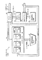
図2は、本発明の一実施形態によるプロセッサ12の一部分を示している。プロセッサ12は、演算論理装置(ALU)24、アドレス・ジェネレータ26、命令パイプライン28、命令復号化回路30、レジスタ・ファイル・セット32、およびベクトル・オフセット・ジェネレータ39を含む。レジスタ・ファイル32は、コンテキスト0 34、コンテキスト1 35、およびコンテキストN 36のような複数のレジスタ・コンテキストを含む。したがって、レジスタ・ファイル32は、N+1個のレジスタ・コンテキストを含み、3つだけを図2に示しているが、プロセッサ12は、いくつのレジスタ・コンテキストをハードウェアがサポートすることが可能であるかに依存して、任意の数のレジスタ・コンテキストを含むことが可能である。また、レジスタ・ファイル32は、制御レジスタ・ファイル38も含む。内部アドレス・バス14がアドレス・ジェネレータ26に結合され、アドレス・ジェネレータ26は、レジスタ・ソース・バス40を介してレジスタ・ファイル32に結合され、内部データ・バス13にも結合される。ベクトル・オフセット・ジェネレータ39は、ベクトル・オフセット・バス27を介してアドレス・ジェネレータ26に結合される。内部データ・バス13は、命令パイプライン28、ALU24、およびレジスタ・ファイル32に結合される。命令復号化回路30は、命令バス29を介して命令パイプライン28に双方向で結合される。レジスタ・ファイル32は、フィールド情報バス42を介してALU24に結合される。
FIG. 2 illustrates a portion of the
図3は、本発明の一実施形態によるレジスタ・コンテキスト51を示している。図3のレジスタ・コンテキスト51は、図2のコンテキスト0〜Nのいずれか1つを表すことが可能である。図3の実施形態では、レジスタ・コンテキスト51は、32個の汎用レジスタ(GPR)50、リンク・レジスタ54、カウント・レジスタ56、条件レジスタ58、整数例外レジスタ60、マシン状態レジスタ62、およびコンテキスト制御レジスタ64を含む。リンク・レジスタ54は、サブルーチンを呼び出す際、およびサブルーチンから戻る際、サブルーチン・リンケージ情報を保持するのに使用される。カウント・レジスタ56は、命令のカウントされるループを処理するためのカウント情報を保持するのに使用される。条件レジスタ58は、条件コード計算の結果を保持するのに使用される。整数例外レジスタ60は、様々な例外ステータスを提供するのに使用される。マシン状態レジスタ62は、プロセッサ12内部の様々な機能のステータスを制御し、それらの機能のステータスを提供するのに使用される。コンテキスト制御レジスタ64は、以下により詳細に説明するとおり、本発明の一実施形態に従ってコンテキスト切り替えを提供するのに使
用される。GPR50の1つは、現在のスタック・ポインタを格納するために確保されたスタック・ポインタ・レジスタ52であることにも留意されたい。
FIG. 3 illustrates a
したがって、レジスタ・コンテキストとは、前述したレジスタ群(コンテキスト51のレジスタ群)の内容を指す。代替の実施形態は、レジスタ・コンテキスト51の同一のレジスタ群のすべて、または一部を有するものとしてレジスタ・コンテキストを定義するか、またはレジスタ・コンテキスト51のレジスタ群とは異なるレジスタ・セットを含むことが可能である。したがって、本明細書で使用するレジスタ・コンテキストは、任意の数の任意のタイプのレジスタを有するように定義することが可能である。通常、レジスタ・コンテキストは、プロセッサに関するプログラマのレジスタ・モデルの全部または一部を形成するレジスタ・リソース群を含む。通常の動作中、または電源投入またはリセットの後、データ処理システム10は、デフォルトでコンテキスト0 34を利用することが可能である。(代替の実施形態では、通常の動作は、デフォルトで異なるコンテキストになることに留意されたい。)しかし、割り込みまたはプロセス切り替えが生じた場合、コンテキスト0 34内の値を壊さないように、データ処理システム10は、その割り込みを処理するため、またはその新たなプロセスまたはスレッドを実行するために、新たなコンテキストを(コンテキスト1ないしNから)選択する。したがって、割り込み処理およびプロセス切り替え(例えば、マルチスレッド)により、データ処理システム10内部でレジスタ・コンテキストを切り替える必要が生じる可能性がある。また、一部の実施形態では、レジスタ・コンテキスト内のレジスタ群の一部を別のレジスタ・コンテキストと共有することが望ましい可能性がある。したがって、以下に説明するとおり、レジスタ・コンテキストの一部分を別のレジスタ・コンテキストにマップして、オーバーヘッドを減らし、コンテキスト切り替え中の速度を高めるのに役立てることが可能である。
Therefore, the register context refers to the contents of the register group described above (the register group of the context 51). Alternative embodiments define the register context as having all or part of the same register group of the
データ処理システム10では、例外および割り込みは、命令パイプライン28の復号化段階または実行段階において認識される。このため、命令が命令復号化回路30に与えられ、復号化された場合、通常の命令処理の代りに、割り込みが認識され、処理されることが可能である。本明細書で説明する一実施形態では、所与の割り込みが他の何らかの割り込みに優先されるかどうかを決める複数の割り込みレベルが存在する。このため、高い優先順位を有する割り込みは、より低い優先順位を有する割り込みより迅速に処理され、より低い優先順位を有する割り込みは、処理を待たなければならない。したがって、同一の優先順位を有する各割り込み、あるいは同一の優先順位を有する各割り込みまたは各タイプの割り込みは、所望される場合、同一のレジスタ・コンテキストを共有することが可能である。
In the
割り込みが受け取られた場合、データ処理システム10は、例外処理シーケンスを実行することを始める。このシーケンス中、ベクトル・オフセット・ジェネレータ39は、ベクトル・オフセット・バス27を介してベクトル・オフセット値をアドレス・ジェネレータ26に与える。アドレス・ジェネレータ26は、ベクトル・オフセット値を使用して、割り込みを処理するために実行が開始されるべき命令アドレスを形成する。一実施形態では、ベクトル・オフセット値に加えて、ベクトル・オフセット・ジェネレータは、割り込み処理のために使用されるべきレジスタ・コンテキストを示すコンテキスト・セレクタも与える。一実施形態では、コンテキスト・セレクタは、ベクトル・オフセット値の一部分であるか、またはベクトル・オフセット・ジェネレータ39によって与えられる別個の値であることが可能である。また、コンテキスト・セレクタは、レジスタ・ファイル32に直接に与えることも可能である。代替の実施形態では、コンテキスト・セレクタは、メモリ(図示せず)から読み取られる値であることが可能であり、あるいは命令を介して受け取られることが可能である。データ処理システム10がレジスタ・ファイル32の中に8つのレジスタ・コンテキストを有するケースでは、コンテキスト・セレクタは、レジスタ・コンテキストの1つを識別するのに使用される3ビットの値であることが可能である。
If an interrupt is received, the
また、データ処理システム10は、1つのプロセスから別のプロセス(それぞれのプロセスは異なるレジスタ・コンテキストで動作することが可能である)に、プロセッサ12が切り替えることが可能である場合、プロセス切り替えを行うことが可能である。例えば、マルチスレッド・アプリケーションでは、プロセッサ12は、異なる処理スレッド(または処理スレッドのグループ)が異なるレジスタ・コンテキストを使用する場合、様々な処理スレッドの間で絶えず切り替えを行うことが可能である。プロセス切り替えのケースでは、割り込みを使用して、プロセス切り替えをデータ処理システム10に示すことが可能である(割り込み処理が切り替えプロセスを含む場合)。あるいは、他の方法を使用して、プロセス切り替えが必要であることをアドレス・ジェネレータ26に示し、アドレス・ジェネレータ26が新たなプロセスの開始アドレスを生成することが可能である。また、プロセス切り替え後、新たなプロセスにいずれのレジスタ・コンテキストが必要とされるかを示すようにコンテキスト・セレクタも与えられる。前述したとおり、コンテキスト・セレクタは、様々な異なる形で(すなわち、ベクトル・オフセット・ジェネレータ39から、メモリから、ユーザ命令からなど)与えることが可能であり、正しいレジスタ・コンテキストが選択されることが可能であるように、レジスタ・ファイル32に直接に、または間接的に(例えば、アドレス・ジェネレータ26を介して)与えることが可能である。
In addition, the
レジスタ・コンテキストが確立されると、プロセッサ12によって実行される命令は、現在、確立されているコンテキストに対応する適切な汎用レジスタ群(GPR群50)または専用レジスタ群(例えば、LR54、CTR56、CR58、XER60、MSR62、またはCTXCR64)を参照する。他のコンテキスト内のレジスタ群は、影響を受けず(以下に説明するとおり、マッピングが確立されていない限り)、このため、現在、確立されているコンテキストに関する命令の実行に先立って、メモリに代替のコンテキストを保存すること、または復元することを実行する必要は全くない。これにより、オーバーヘッドの節減が可能になる。
Once the register context is established, the instructions executed by the
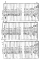
図4および図5は、データ処理システム10内部で使用することが可能なレジスタ・コンテキスト内の典型的なマッピングを示している。図4は、3つのレジスタ・コンテキスト、すなわち、コンテキスト0 70、コンテキスト1 72、およびコンテキスト2 74を示している。以上のレジスタ・コンテキストは、図2のコンテキスト0〜Nの範囲内のコンテキストの3つを表すことが可能である。図4の例では、コンテキスト0 70は、データ処理システム10の通常の動作に対応し、コンテキスト1 72は、重要な割り込み(最高優先順位)に対応し、コンテキスト2 74は、外部割込み(低い優先順位)に対応するものと想定する。前述したとおり、一部のケースでは、複数のレジスタ・コンテキストがレジスタ群の一部を「共有する」ことが望ましい。したがって、図4の例では、矢印82で示すとおり、レジスタ・コンテキスト2 74のスタック・ポインタ・レジスタ80が、レジスタ・コンテキスト1 72のスタック・ポインタ78にマップされ、レジスタ・コンテキスト1 72とレジスタ・コンテキスト2 74が同一のスタック・ポインタを共有することが可能であり、両方のレジスタ・コンテキストにおいて同一のスタック・ポインタ値が使用されるようになっていることを示している。このマッピングは、オーバーヘッドを減らし、スタック・ポインタの整合性を保つのに役立つ。したがって、外部割り込みを処理するときには、コンテキスト2 74がデータ処理システム10によって選択される。しかし、スタック・ポインタ・レジスタ80がスタック・ポインタ・レジスタ78にマップされているので、レジスタ・コンテキスト1 72内のスタック・ポインタ・レジスタ78が、そのスタック・ポインタにアクセスするためにレジスタ・コンテキスト2 74における動作中にアクセスされる。つまり、レジスタ・コンテキスト2 74を選択する現在のコンテキスト値で動作している間、スタック・ポインタ・レジスタ80にアクセスしようと試みる命令およびその他の動作は、レジスタ・コンテキス
ト1 72内のスタック・ポインタ・レジスタ78にアクセスするように向けかえられる。これにより、別々のスタック・ポインタ・レジスタ80と78を同期させるオーバーヘッドなしに、コンテキスト1とコンテキスト2の間で単一の矛盾しないスタックおよびスタック・ポインタ値が共有されることが可能になる。
FIGS. 4 and 5 illustrate exemplary mappings within a register context that can be used within the
スタック・ポインタ・レジスタ76(コンテキスト0 70の)とスタック・ポインタ・レジスタ78(コンテキスト1 72の)はマップされていないことに留意されたい。したがって、これらのレジスタ・コンテキストで動作している場合、スタック・ポインタにアクセスする際に他のいずれのレジスタ・コンテキストにもアクセスする必要がない。レジスタ・コンテキスト70、72、および74のそれぞれの中のコンテキスト制御レジスタ77、79、および75はそれぞれ、対応するレジスタ・コンテキストのスタック・ポインタがマップされているかどうかを示し、マップされている場合、他のいずれのレジスタ・コンテキストにマップされているかを示す。コンテキスト制御レジスタの詳細を、図6を参照して以下により詳細に説明する。
Note that stack pointer register 76 (for
図5は、別の例による3つのレジスタ・コンテキスト、すなわち、レジスタ・コンテキスト1 90、レジスタ・コンテキスト2 92、およびレジスタ・コンテキスト3 94を示している。図4の場合と同様に、図5のレジスタ・コンテキストは、図2のレジスタ・コンテキスト0〜Nのレジスタ・コンテキストの3つを表すことが可能である。図5の例では、レジスタ・コンテキスト1 90は、プロセスAに対応し、レジスタ・コンテキスト2 92は、プロセスBに対応し、レジスタ・コンテキスト3 94は、プロセスCに対応する。したがって、データ処理システム10は、プロセスAを実行している場合、レジスタ・コンテキスト1 90で動作する。プロセス切り替え時(例えばプロセスAからプロセスBへの切り替え)、コンテキスト・セレクタにより、プロセスBを実行する際に使用するためのレジスタ・コンテキスト2 92が選択される。図4に関連して前述したとおり、スタック・ポインタ・レジスタのそれぞれは、異なるレジスタ・コンテキストにマップされる能力を有する。例えば、図5で、レジスタ・コンテキスト1 90のスタック・ポインタ・レジスタ96が、矢印124で示すとおり、レジスタ・コンテキスト2 92のスタック・ポインタ・レジスタ98にマップされる。したがって、プロセスAを実行している(レジスタ・コンテキスト1 90を使用して)場合、スタック・ポインタへのアクセスにより、実際には、異なるレジスタ・コンテキスト(すなわち、レジスタ・コンテキスト2 92)内のスタック・ポインタ・レジスタ98へのアクセスがもたらされる。ただし、レジスタ・コンテキスト3 94のスタック・ポインタ・レジスタ100はマップされていないことに留意されたい。また、一実施形態では、階層型マッピングを有することも可能である。例えば、スタック・ポインタ・レジスタ96がスタック・ポインタ・レジスタ98にマップされるのと同様に、スタック・ポインタ・レジスタ98も、例えば、スタック・ポインタ・レジスタ100にマップされることが可能である。また、特定のスタック・ポインタ・レジスタに、複数のスタック・ポインタ・レジスタがマップされることも可能である。例えば、スタック・ポインタ・レジスタ98に、スタック・ポインタ・レジスタ100とスタック・ポインタ・レジスタ96がマップされることが可能である。その他のマッピングも同様に可能である。
FIG. 5 shows three register contexts according to another example: register
図5のレジスタ・コンテキスト群は、レジスタのグループ化も含む。例えば、汎用レジスタ群は、4つのレジスタのグループにグループ化される。レジスタ・コンテキスト1 90において、GPR4〜7が一緒にグループ化されてレジスタ・グループ102になり、GPR8〜11が一緒にグループ化されてレジスタ・グループ104になり、GPR28〜31がグループ化されてレジスタ・グループ106になる。したがって、レジスタ・コンテキスト1 90は、図5の例では、それぞれ4つのレジスタの3つのグループ(グループ102、104、および106)を含み、これらのグループのそれぞれが、異なるレジスタ・コンテキストにマップされる(グループとして)ことが可能である。代替の実
施形態では、任意の数およびタイプのレジスタをグループ化することが可能である。あるいは、所望される細分性に依存して、それぞれの個別のレジスタを別個のグループと見なすことが可能である。同様に、レジスタ・コンテキスト2 92は、4つのレジスタの3つのグループ、すなわち、GPR4〜7を有するグループ114、GPR8〜11を有するグループ116、およびGPR28〜31を有するグループ118)を含む。また、レジスタ・コンテキスト3 94も、4つのレジスタの3つのグループ、すなわち、GPR4〜7を有するグループ108、GPR8〜11を有するグループ110、およびGPR28〜31を有するグループ112)を含む。以上のグループ化により、レジスタのグループが、異なるレジスタ・コンテキストの間でマッピングされることが可能になる。
The register context group of FIG. 5 also includes register grouping. For example, the general purpose register group is grouped into groups of four registers. In register context 190, GPRs 4-7 are grouped together to become
例えば、矢印120で示すとおり、レジスタ・コンテキスト2 92のグループ118が、レジスタ・コンテキスト1 90のグループ106にマップされる。矢印126で示すとおり、レジスタ・コンテキスト3 94のグループ112も、レジスタ・コンテキスト1 90のグループ106にマップされる。つまり、グループ106のレジスタ群は、3つすべてのレジスタ・コンテキスト、すなわち、レジスタ・コンテキスト1 90、レジスタ・コンテキスト2 92、およびレジスタ・コンテキスト3 94によって共有される。したがって、プロセスBまたはプロセスCを実行している場合、現在のレジスタ・コンテキスト(それぞれ、レジスタ・コンテキスト2 92またはレジスタ・コンテキスト3 94)のGPR28〜31へのアクセスにより、実際には、レジスタ・コンテキスト1 90のGPR28〜31へのアクセスがもたらされる。やはり図5に示されていることとして、矢印122で示すとおり、レジスタ・コンテキスト1 90のグループ104が、レジスタ・コンテキスト2 92のグループ116にマップされている。つまり、グループ116のレジスタ群は、レジスタ・コンテキスト1 90とレジスタ・コンテキスト2 92の両方によって共有される。したがって、プロセスAを実行している場合、現在のレジスタ・コンテキストのGPR8〜11へのアクセスにより、実際には、レジスタ・コンテキスト2 92のGPR8〜11へのアクセスがもたらされる。したがって、単一のレジスタ(スタック・ポインタ・レジスタ96、98、または100のような)のマッピングであるか、レジスタのグループのマッピングであるかに関わらず、任意の数のマッピングが存在することが可能である。また、各レジスタ・コンテキストは、あるレジスタ群を1つのレジスタ・コンテキストにマップしており、他のレジスタ群をもう1つのレジスタ・コンテキストにマップしていることも可能である。また、レジスタ、またはグループのレジスタに、複数のレジスタ・コンテキストのレジスタ群がマップされていることも可能である。
For example, as shown by
各レジスタ・コンテキストのマッピングは、各レジスタ・コンテキストのコンテキスト制御レジスタ(例えば、図5のコンテキスト制御レジスタ128、130、および132)の中で定義される。したがって、図2の各レジスタ・コンテキスト0〜Nは、各レジスタ・コンテキストの中に含められることが可能である(図4および5のように)か、または別々に(図2の制御レジスタ・ファイル38の中などに)格納されることが可能な、対応するコンテキスト制御レジスタを有する。図6は、本発明の一実施形態によるコンテキスト制御レジスタ140の内容を示している。コンテキスト制御レジスタ140は、図4のコンテキスト制御レジスタ77、79、75、または図5のコンテキスト制御レジスタ128、130、および132を指すことが可能である。一実施形態では、コンテキスト制御レジスタ140は、レジスタ群のマッピングを制御する様々な異なるフィールドを有し、現在のコンテキスト情報、代替のコンテキスト情報、および保存されたコンテキスト情報を保持する専用32ビット・レジスタである。
The mapping of each register context is defined in the context control registers (eg, context control registers 128, 130, and 132 of FIG. 5) for each register context. Thus, each register context 0-N of FIG. 2 can be included in each register context (as in FIGS. 4 and 5) or separately (control register file of FIG. 2). A corresponding context control register that can be stored. FIG. 6 illustrates the contents of the context control register 140 according to one embodiment of the invention. The context control register 140 may refer to the context control registers 77, 79, 75 of FIG. 4 or the context control registers 128, 130, and 132 of FIG. In one embodiment, the
コンテキスト制御レジスタ140のビット0は、複数のレジスタ・コンテキストの使用を有効にするコンテキスト・イネーブル・フィールド142に対応する。例えば、コンテキスト・イネーブル・フィールド142がネゲートされた場合、単一のコンテキストだけ
が有効にされ、コンテキスト制御140内の他のすべての制御フィールドは無視され、現在のコンテキストは、既定のレジスタ・コンテキスト(図2に示した実施形態では、レジスタ・コンテキスト0 34である)に設定される。コンテキスト・イネーブル・フィールド142がアサートされた場合、複数のコンテキストが有効になる。ビット3〜5は、ハードウェアによってサポートされる最大コンテキスト数を示す読み取り専用フィールドであるコンテキスト数フィールド144に対応する。図6の例では、000という値により、1つのコンテキストがサポートされることが示され、111という値により、8つのレジスタ・コンテキストがハードウェアによってサポートされることが示される。データ処理システム10が、8つより多くのレジスタ・コンテキストをサポートすることが可能な場合、コンテキスト数フィールド144のために追加のビットを使用することが可能である。ただし、図6の実施形態では、最大で8つのレジスタ・コンテキストがサポートされるものと想定する。
ビット6〜8は、現在、有効にされているレジスタ・コンテキストを定義する現行コンテキスト・フィールド146に対応する。一実施形態では、このフィールドは、リセット時にクリアされて0になり、既定のレジスタ・コンテキストはレジスタ・コンテキスト0であることを示す。現行コンテキスト・フィールド146は、図2のベクトル・オフセット・ジェネレータ39によって与えられるなど、様々な異なる形で与えられることが可能な前述したコンテキスト・セレクタに対応する。したがって、コンテキスト切り替え(割り込み、またはプロセス切り替えによって生じさせられる)時に、現行コンテキスト・フィールド146は、コンテキスト・セレクタによって示される新たなレジスタ・コンテキストに設定される。例えば、図5を参照すると、データ処理システム10が現在、プロセスAにおいて実行されている場合、プロセスBへのコンテキスト切り替え時に、コンテキスト・セレクタによりレジスタ・コンテキスト2が示され、2という値が、レジスタ・コンテキスト2 92のコンテキスト制御レジスタの現行コンテキスト・フィールドに書き込まれる。
Bits 6-8 correspond to the
各レジスタ・コンテキストは、独自のコンテキスト制御レジスタを有し、フィールドのいくつかは、異なるコンテキスト制御レジスタの間で共有されることが可能であることに留意されたい。例えば、単一のコンテキスト・イネーブル・ビット、単一のコンテキスト数フィールド、および単一の現行コンテキスト・フィールドが実装されることが可能であり、すべてのコンテキスト制御レジスタによって使用される。というのは、値は、異なるコンテキスト制御レジスタの間で常に同一だからである。代替の実施形態は、各コンテキスト制御レジスタに関してコンテキスト・イネーブル・フィールドまたはコンテキスト数フィールド、または現行コンテキスト・フィールドを使用することも可能であるが、それぞれに関して単一の共有フィールドを使用することにより、ハードウェア要件が少なくなる。 Note that each register context has its own context control register, and some of the fields can be shared between different context control registers. For example, a single context enable bit, a single context number field, and a single current context field can be implemented and used by all context control registers. This is because the value is always the same between different context control registers. Alternative embodiments may use a context enable field or context number field, or a current context field for each context control register, but by using a single shared field for each, Wear requirements are reduced.
ビット9〜11は、前に有効にされたコンテキストを定義する保存済みコンテキスト・フィールド148に対応する。このフィールドも、リセット時にクリアされて0になることが可能であることに留意されたい。したがって、プロセスAからプロセスBに切り替える前述の例では(図5参照)、現行コンテキスト・フィールドは、2(レジスタ・コンテキスト2 92を表す)に設定され、保存済みコンテキスト・フィールドは、1(前のコンテキスト、レジスタ・コンテキスト1 90を表す)に設定される。
Bits 9-11 correspond to a saved
ビット12〜14は、レジスタ・グループに関するコンテキスト・マッピングを定義するのに使用される代替で有効にされるコンテキストを定義する代替コンテキスト・フィールド150に対応する。ビット15〜18は、マッピング・フィールド151に対応する。ビット15は、レジスタ・グループA(GPR4〜7と定義される)に対応し、ビット16は、レジスタ・グループB(GPR8〜11と定義される)に対応し、ビット17は
、レジスタ・グループC(GPR16〜23と定義される)に対応し、ビット18は、レジスタ・グループD(GPR27〜31と定義される)に対応する。レジスタ・グループA〜Dのそれぞれは、対応するビットをアサートすることによって独立に有効にすることが可能である。例えば、ビット15がアサートされた場合、グループAが有効にされて、グループAが代替コンテキスト・フィールドによって定義されたレジスタ・コンテキストにマップされるようになる。ビット15がネゲートされた場合、グループAはマップされない。同様に、ビット16、ビット17、またはビット18がアサートされた場合、レジスタの対応するグループ(それぞれB、C、またはD)が、代替コンテキスト・フィールドによって定義されたレジスタ・コンテキストにマップされる。ビット16、ビット17、またはビット18がネゲートされた場合、レジスタの対応するグループ(それぞれB、C、またはD)はマップされない。したがって、図5を参照すると、レジスタ・コンテキスト1 90のコンテキスト制御レジスタが、代替コンテキスト・フィールドの中に2を含み、レジスタの選択された1つまたは複数のグループがレジスタ・コンテキスト2 92にマップされることを示している。また、ビット16(GPR8〜11を有するグループBに対応する)がアサートされて、レジスタ・コンテキスト1 90のグループ104がレジスタ・コンテキスト2 92のグループ116にマップされるようになる。
Bits 12-14 correspond to an
図6の典型的なコンテキスト制御レジスタである、コンテキスト制御レジスタ140では、単一の代替コンテキスト・フィールドが利用可能であり、各グループ(A〜D)がその同じ代替レジスタ・コンテキストにマップされるように有効にされることが可能である。つまり、グループAが特定のレジスタ・コンテキストにマップされた場合、グループC〜Dは、その同じコンテキストにだけマップすることが可能である。ただし、代替の実施形態では、レジスタのそれぞれの別個のグループ(グループA〜Dのような)が、対応する代替コンテキスト・フィールドを有して、異なる代替レジスタ・コンテキストにマップされることが可能であるようになっていてもよい。あるいは、グループのグループに関して別個の代替コンテキスト・フィールド(例えば、グループAおよびグループBに関して1つの代替コンテキスト・フィールド、グループCおよびグループDに関して別の代替コンテキスト・フィールド)を使用することが可能である。また、グループは、任意の形で定義することが可能である。例えば、各グループは、4つのより多い、または少ないレジスタを有することが可能であり、各グループが単一のレジスタであること、または各グループが異なる数のレジスタを有することが可能である。また、代替の実施形態では、より多い、またはより少ないグループをより多い、またはより少ない代替コンテキスト・フィールドとともに使用することが可能である。したがって、図6のコンテキスト制御レジスタ140は、一例に過ぎない。また、各フィールドは、必要に応じて、より多い、またはより少ないビットを使用してフィールドの値を表すことも可能である。コンテキスト制御140は、未使用のビット1、2、19〜23、および28〜31を含むが、代替の実施形態は、未使用のビットを全く含まないこと、またはコンテキスト制御情報を格納するのに複数のレジスタを要することも可能である。
In the
コンテキスト制御レジスタ140のビット24は、図4と図5の両方に関連して説明したとおり、スタック・ポインタのマッピングを有効にするスタック・ポインタ・コンテキスト・イネーブル・フィールド152に対応する。ビット25〜27は、スタック・ポインタに関する代替レジスタ・コンテキストを選択するスタック・ポインタ・コンテキスト選択フィールド154に対応する。したがって、ビット24がアサートされた場合、スタック・ポインタは、スタック・ポインタ・コンテキスト選択フィールド154によって示されるレジスタ・コンテキストにマップされるが、ビット24がネゲートされた場合、スタック・ポインタはマップされない(すなわち、現行コンテキスト・フィールド146によって定義された現行コンテキストに留まる)。スタック・ポインタ・コンテキスト選択フィールド154は、データ処理システム10内部の8つのレジスタ・コンテキストのいずれがスタック・ポインタに関する代替のコンテキストとして使用されるべきかを示すこ
とが可能な3ビットの値である。例えば、000という値が、レジスタ・コンテキスト0に対応し、111がレジスタ・コンテキスト7に対応することが可能である。したがって、スタック・ポインタ・コンテキスト選択フィールド154が001に設定されている場合、(かつスタック・ポインタ・コンテキスト・イネーブル・フィールド152がアサートされた場合)、現在のコンテキストのスタック・ポインタは、レジスタ・コンテキスト1にマップされる。例えば、図4を再び参照すると、レジスタ・コンテキスト2 74のコンテキスト制御レジスタのスタック・ポインタ・コンテキスト・イネーブル・フィールドがアサートされ、スタック・ポインタ・コンテキスト選択フィールドが001に設定されて、スタック・ポインタ・レジスタ80がレジスタ・コンテキスト1 72のスタック・ポインタ・レジスタ78にマップされることを示す。また、代替の実施形態は、スタック・ポインタの共有を可能にするだけではない他の個々のレジスタのマッピングも可能にするフィールドを含むことが可能であることにも留意されたい。
コンテキスト制御レジスタは、様々な異なる形でプログラミングすることが可能である。例えば、一実施形態では、各コンテキスト制御レジスタを、直接にユーザによってプログラミングすることが可能である。あるいは、コンテキスト制御レジスタは、現在のコンテキスト制御レジスタの代替のコンテキスト・フィールドを使用して間接的にマップされることが可能である。例えば、一実施形態では、電源投入またはリセットの後、データ処理システムは、デフォルトでレジスタ・コンテキスト0になる。次に、代替コンテキスト・フィールドが、いずれのレジスタ・コンテキストのコンテキスト制御レジスタがプログラミングされるかを示す値に設定されることが可能である。例えば、レジスタ・コンテキスト0になっている間、レジスタ・コンテキスト0のコンテキスト制御レジスタの代替コンテキスト・フィールドに2という値を書き込むことにより、専用レジスタを介してレジスタ・コンテキスト2のコンテキスト制御レジスタのプログラミングへのアクセスが可能になる。コンテキスト制御フィールドのすべてがプログラミングされた後、それらのフィールドがすべて同時に有効にされる(単一の共有コンテキスト・イネーブル・フィールドを有するケースでは、そのビットをアサートすることによって行われる)ことが可能である。また、一実施形態では、コンテキスト制御レジスタ群のプログラミング中、割り込み処理をオフにすることが可能である。
The context control register can be programmed in a variety of different ways. For example, in one embodiment, each context control register can be programmed directly by the user. Alternatively, the context control register can be mapped indirectly using an alternative context field of the current context control register. For example, in one embodiment, after power-up or reset, the data processing system defaults to register
コンテキスト制御レジスタ140は、特定のフィールドおよびビットの位置に関連して説明してきたことに留意されたい。代替の実施形態は、必要に応じて、より多い、またはより少ないフィールドを含むことが可能であり、各フィールドは、必要に応じて、より多い、またはより少ないビットを含むことが可能であることに留意されたい。また、代替の実施形態では、コンテキスト制御レジスタ群は、データ処理システム10内部のいずれの場所に配置してもよいし、あるいはデータ処理システム10の外部に配置してもよい。
Note that the
かくして、オーバーヘッドのより少ない、柔軟性のあるコンテキスト選択を提供するために、どのようにコンテキスト制御レジスタを使用可能であるかを理解することが可能であろう。データ処理システム10内部のコンテキスト切り替え時に、新たなレジスタ・コンテキストのコンテキスト制御レジスタが更新される。例えば、新たなレジスタ・コンテキストは、現行コンテキスト・フィールドに書き込まれ、前のコンテキストは、保存済みコンテキスト・フィールドに書き込まれ、新たなレジスタ・コンテキスト内で動作する際に、マッピング・フィールドの中で与えられるレジスタ・マッピングが使用される。レジスタ・マッピングにより、異なるレジスタ・コンテキストがレジスタ値を共有することが可能になる。また、レジスタ・マッピングにより、現在のレジスタ・コンテキストのコンテキスト制御レジスタによって定義される現在のレジスタ・コンテキスト外部の他のレジスタ・コンテキスト群のアクセスも可能になる。また、ユーザがプログラミング可能なコンテキスト制御レジスタ群により、どのようにマッピングを定義するかについて柔軟性が可能になる。したがって、本明細書で説明する本発明の一態様により、代替レジスタ・コ
ンテキストの一部分を現在のレジスタ・コンテキストにマップする(またその逆を行う)柔軟性のある機構が提供され、複数のコンテキストの間で共通のスタック・ポインタの柔軟性のある共有が可能になり、リアルタイム・パフォーマンスの向上がもたらされる。現在のコンテキストの一部分を代替のコンテキストにマップすることにより、動作コンテキスト間で情報値を転送することのオーバーヘッドを除く、またはなくすことが可能になり、パフォーマンスの向上および柔軟性がもたらされる。
Thus, it will be understood how the context control register can be used to provide flexible context selection with less overhead. The context control register of the new register context is updated when the context in the
以上の明細では、本発明を特定の実施形態に関連して説明した。しかし、添付の特許請求の範囲に記載する本発明の範囲を逸脱することなく、様々な改変および変更を行うことが可能であることが当業者には認められよう。例えば、ブロック図は、例示したブロックとは異なるブロックを有することが可能であり、より多い、またはより少ないブロックを有すること、または異なる形で構成されることも可能である。したがって、本明細書および図は、限定するものではなく、例示するものと考えられるべきであり、すべてのそのような改変形態が本発明の範囲に含まれるものとする。 In the foregoing specification, the invention has been described with reference to specific embodiments. However, one of ordinary skill in the art appreciates that various modifications and changes can be made without departing from the scope of the present invention as set forth in the claims below. For example, the block diagram may have different blocks than the illustrated blocks, may have more or fewer blocks, or may be configured differently. The specification and drawings are accordingly to be regarded as illustrative rather than limiting and all such modifications are intended to be included within the scope of the present invention.
特定の実施形態に関して、利点、その他の優位点、および問題解決法を説明してきた。しかし、これらの利点、優位点、問題解決法、ならびに何らかの利点、優位点、または問題解決法を生じさせる、またはより顕著し得る要素は、一部または全部の請求項の不可欠な、必要な、または本質的な特徴または要素と解釈すべきではない。本明細書で使用する「からなる(comprises)」、「comprising(からなる)」、またはこの用語の他のあらゆる変化形は、排他的でない包含を範囲に含むものとし、したがって、要素のリストからなるプロセス、方法、物品、または装置は、それらの要素を含むだけでなく、明確にリストアップされていない、またはそのようなプロセス、方法、物品、または装置に固有でない他の要素も含み得る。 Advantages, other advantages, and problem solutions have been described with respect to particular embodiments. However, these advantages, advantages, problem solving, as well as elements that may give rise to or become more prominent in some advantage, advantage, or problem solving are essential, necessary, or essential in some or all claims, Or should not be construed as essential features or elements. As used herein, “comprises”, “comprising”, or any other variation of this term is intended to cover non-exclusive inclusions and thus consist of a list of elements. A process, method, article, or apparatus not only includes those elements, but may also include other elements that are not explicitly listed or are not unique to such processes, methods, articles, or devices.
Claims (7)
前記レジスタファイル(32)は、割込動作毎、プロセス動作毎、およびスレッド動作毎のうちの少なくとも一つに応じてそれぞれ前記プロセッサ(12)によって切替えて用いられる複数のレジスタコンテキストを有し、
前記レジスタコンテキスト(74)には、当該レジスタコンテキスト(74)の汎用レジスタが他のレジスタコンテキスト(72)の汎用レジスタにマップ(82)されているか否かを示すコンテキスト制御レジスタ(75)がそれぞれ対応付けられ、
前記プロセッサ(12)がアクセスした前記汎用レジスタが他の汎用レジスタにマップ(82)されている場合、前記プロセッサ(12)は当該他の汎用レジスタにもアクセスすることを特徴とする、データ処理システム。A data processing system (10) comprising a processor (12) having a register file (32),
The register file (32) has a plurality of register contexts that are used by being switched by the processor (12) according to at least one of an interrupt operation, a process operation, and a thread operation ,
Each of the register contexts (74) corresponds to a context control register (75) indicating whether or not the general-purpose registers of the register context (74) are mapped (82) to the general-purpose registers of other register contexts (72). Attached,
A data processing system characterized in that, when the general-purpose register accessed by the processor (12) is mapped (82) to another general-purpose register, the processor (12) also accesses the other general-purpose register. .
スタックポインタのマッピングを有効にするスタックポインタコンテキストイネーブルフィールド(152)と;
前記スタックポインタに関するマップ先のレジスタコンテキストを選択するスタックポインタコンテキスト選択フィールド(154)と
を有する、請求項1〜3何れか一項記載のデータ処理システム。The context control register (140) further includes:
A stack pointer context enable field (152) that enables stack pointer mapping;
The data processing system according to any one of claims 1 to 3, further comprising a stack pointer context selection field (154) for selecting a register context of a mapping destination for the stack pointer.
アサートされることによって複数のレジスタコンテキストを有効にするイネーブルフィールド(142)を有する、請求項1〜4何れか一項記載のデータ処理システム。The context control register (140) further includes:
The data processing system of any of claims 1 to 4, comprising an enable field (142) that, when asserted, enables a plurality of register contexts .
現行のレジスタコンテキストの前に実行されていたレジスタコンテキストを特定するための保存済コンテキストフィールド(148)を含む、請求項1〜5何れか一項記載のデータ処理システム。The context control register (140) further includes:
6. A data processing system according to any one of the preceding claims, comprising a saved context field (148) for identifying a register context that has been executed before the current register context.
前記レジスタファイル(32)は、割込動作毎、プロセス動作毎、およびスレッド動作毎のうちの少なくとも一つに応じてそれぞれ前記プロセッサ(12)によって切替えて用いられる複数のレジスタコンテキストを有し、
前記レジスタコンテキスト(74)には、当該レジスタコンテキスト(74)の汎用レジスタが他のレジスタコンテキスト(72)の汎用レジスタにマップ(82)されているか否かを示すコンテキスト制御レジスタ(75)がそれぞれ対応付けられ、
前記プロセッサ(12)がアクセスした前記汎用レジスタが他の汎用レジスタにマップ(82)されている場合、前記プロセッサ(12)は当該他の汎用レジスタにもアクセスすることを特徴とする、データ処理方法。A data processing method in a processor (12) having a register file (32), comprising:
The register file (32) has a plurality of register contexts that are used by being switched by the processor (12) according to at least one of an interrupt operation, a process operation, and a thread operation ,
Each of the register contexts (74) corresponds to a context control register (75) indicating whether or not the general-purpose registers of the register context (74) are mapped (82) to the general-purpose registers of other register contexts (72). Attached,
A data processing method characterized in that, when the general-purpose register accessed by the processor (12) is mapped (82) to another general-purpose register, the processor (12) also accesses the other general-purpose register. .
Applications Claiming Priority (2)
| Application Number | Priority Date | Filing Date | Title |
|---|---|---|---|
| US10/159,386 US7117346B2 (en) | 2002-05-31 | 2002-05-31 | Data processing system having multiple register contexts and method therefor |
| PCT/US2003/014215 WO2003102723A2 (en) | 2002-05-31 | 2003-05-07 | Data processing system having multiple register contexts and method therefor |
Publications (3)
| Publication Number | Publication Date |
|---|---|
| JP2006502470A JP2006502470A (en) | 2006-01-19 |
| JP2006502470A5 JP2006502470A5 (en) | 2006-06-15 |
| JP4409427B2 true JP4409427B2 (en) | 2010-02-03 |
Family
ID=29582888
Family Applications (1)
| Application Number | Title | Priority Date | Filing Date |
|---|---|---|---|
| JP2004509742A Expired - Fee Related JP4409427B2 (en) | 2002-05-31 | 2003-05-07 | Data processing system having multiple register contexts and method for the system |
Country Status (8)
| Country | Link |
|---|---|
| US (1) | US7117346B2 (en) |
| EP (1) | EP1573444A2 (en) |
| JP (1) | JP4409427B2 (en) |
| KR (1) | KR100989215B1 (en) |
| CN (1) | CN100472453C (en) |
| AU (1) | AU2003225300A1 (en) |
| TW (1) | TWI323847B (en) |
| WO (1) | WO2003102723A2 (en) |
Families Citing this family (46)
| Publication number | Priority date | Publication date | Assignee | Title |
|---|---|---|---|---|
| US20040098568A1 (en) * | 2002-11-18 | 2004-05-20 | Nguyen Hung T. | Processor having a unified register file with multipurpose registers for storing address and data register values, and associated register mapping method |
| US7631307B2 (en) * | 2003-12-05 | 2009-12-08 | Intel Corporation | User-programmable low-overhead multithreading |
| US7401206B2 (en) * | 2004-06-30 | 2008-07-15 | Sun Microsystems, Inc. | Apparatus and method for fine-grained multithreading in a multipipelined processor core |
| US7516311B2 (en) * | 2005-01-27 | 2009-04-07 | Innovasic, Inc. | Deterministic microcontroller context arrangement |
| US7562207B2 (en) * | 2005-01-27 | 2009-07-14 | Innovasic, Inc. | Deterministic microcontroller with context manager |
| KR100728899B1 (en) * | 2005-10-27 | 2007-06-15 | 한국과학기술원 | High-performance multithreaded embedded processor with multiple register sets and hardware task manager |
| US7590774B2 (en) * | 2005-12-01 | 2009-09-15 | Kabushiki Kaisha Toshiba | Method and system for efficient context swapping |
| CN103646009B (en) | 2006-04-12 | 2016-08-17 | 索夫特机械公司 | The apparatus and method that the instruction matrix of specifying parallel and dependent operations is processed |
| EP2527972A3 (en) | 2006-11-14 | 2014-08-06 | Soft Machines, Inc. | Apparatus and method for processing complex instruction formats in a multi- threaded architecture supporting various context switch modes and virtualization schemes |
| US8341641B2 (en) * | 2007-08-16 | 2012-12-25 | Kernelon Silicon Inc. | Task processor |
| US9135144B2 (en) | 2009-10-22 | 2015-09-15 | Freescale Semiconductor, Inc. | Integrated circuits and methods for debugging |
| EP3156896B1 (en) | 2010-09-17 | 2020-04-08 | Soft Machines, Inc. | Single cycle multi-branch prediction including shadow cache for early far branch prediction |
| WO2012093288A1 (en) * | 2011-01-03 | 2012-07-12 | Freescale Semiconductor, Inc. | Integrated circuit device and method for performing conditional negation of data |
| TWI518504B (en) | 2011-03-25 | 2016-01-21 | 軟體機器公司 | Register file segments for supporting code block execution by using virtual cores instantiated by partitionable engines |
| EP2689327B1 (en) | 2011-03-25 | 2021-07-28 | Intel Corporation | Executing instruction sequence code blocks by using virtual cores instantiated by partitionable engines |
| KR101636602B1 (en) | 2011-03-25 | 2016-07-05 | 소프트 머신즈, 인크. | Memory fragments for supporting code block execution by using virtual cores instantiated by partitionable engines |
| WO2012131437A1 (en) * | 2011-03-30 | 2012-10-04 | Freescale Semiconductor, Inc. | Integrated circuit device and method for enabling cross-context access |
| KR101639854B1 (en) | 2011-05-20 | 2016-07-14 | 소프트 머신즈, 인크. | An interconnect structure to support the execution of instruction sequences by a plurality of engines |
| US9940134B2 (en) | 2011-05-20 | 2018-04-10 | Intel Corporation | Decentralized allocation of resources and interconnect structures to support the execution of instruction sequences by a plurality of engines |
| US10078515B2 (en) * | 2011-10-03 | 2018-09-18 | International Business Machines Corporation | Tracking operand liveness information in a computer system and performing function based on the liveness information |
| WO2013077875A1 (en) | 2011-11-22 | 2013-05-30 | Soft Machines, Inc. | An accelerated code optimizer for a multiengine microprocessor |
| CN108427574B (en) | 2011-11-22 | 2022-06-07 | 英特尔公司 | Microprocessor accelerated code optimizer |
| WO2013099414A1 (en) * | 2011-12-26 | 2013-07-04 | インターナショナル・ビジネス・マシーンズ・コーポレーション | Register mapping method |
| WO2014108747A1 (en) * | 2013-01-10 | 2014-07-17 | Freescale Semiconductor, Inc. | Integrated circuit processor and method of operating a integrated circuit processor |
| US10275255B2 (en) | 2013-03-15 | 2019-04-30 | Intel Corporation | Method for dependency broadcasting through a source organized source view data structure |
| WO2014150991A1 (en) | 2013-03-15 | 2014-09-25 | Soft Machines, Inc. | A method for implementing a reduced size register view data structure in a microprocessor |
| US10140138B2 (en) | 2013-03-15 | 2018-11-27 | Intel Corporation | Methods, systems and apparatus for supporting wide and efficient front-end operation with guest-architecture emulation |
| US9569216B2 (en) | 2013-03-15 | 2017-02-14 | Soft Machines, Inc. | Method for populating a source view data structure by using register template snapshots |
| US9811342B2 (en) | 2013-03-15 | 2017-11-07 | Intel Corporation | Method for performing dual dispatch of blocks and half blocks |
| US9891924B2 (en) | 2013-03-15 | 2018-02-13 | Intel Corporation | Method for implementing a reduced size register view data structure in a microprocessor |
| US9904625B2 (en) | 2013-03-15 | 2018-02-27 | Intel Corporation | Methods, systems and apparatus for predicting the way of a set associative cache |
| US9886279B2 (en) | 2013-03-15 | 2018-02-06 | Intel Corporation | Method for populating and instruction view data structure by using register template snapshots |
| WO2014150971A1 (en) | 2013-03-15 | 2014-09-25 | Soft Machines, Inc. | A method for dependency broadcasting through a block organized source view data structure |
| CN105247484B (en) | 2013-03-15 | 2021-02-23 | 英特尔公司 | Method for emulating a guest centralized flag architecture using a locally distributed flag architecture |
| WO2014150806A1 (en) | 2013-03-15 | 2014-09-25 | Soft Machines, Inc. | A method for populating register view data structure by using register template snapshots |
| WO2014151018A1 (en) | 2013-03-15 | 2014-09-25 | Soft Machines, Inc. | A method for executing multithreaded instructions grouped onto blocks |
| US10031770B2 (en) * | 2014-04-30 | 2018-07-24 | Intel Corporation | System and method of delayed context switching in processor registers |
| US9971604B2 (en) | 2015-02-26 | 2018-05-15 | International Business Machines Corporation | History buffer for multiple-field registers |
| US9996353B2 (en) | 2015-02-26 | 2018-06-12 | International Business Machines Corporation | Universal history buffer to support multiple register types |
| US10067766B2 (en) * | 2015-02-26 | 2018-09-04 | International Business Machines Corporation | History buffer with hybrid entry support for multiple-field registers |
| US10802866B2 (en) * | 2015-04-30 | 2020-10-13 | Microchip Technology Incorporated | Central processing unit with DSP engine and enhanced context switch capabilities |
| JP2017037370A (en) | 2015-08-06 | 2017-02-16 | 富士通株式会社 | Computer, process control method and process control program |
| GB2577729C (en) * | 2018-10-04 | 2021-10-27 | Advanced Risc Mach Ltd | Processor with Register Bank having Banked Versions of a Register each Associated with an Operating State of the Processor |
| CN110928574A (en) * | 2019-11-20 | 2020-03-27 | 深圳市汇顶科技股份有限公司 | Microcontroller, interrupt processing chip, device and interrupt processing method |
| US11663010B2 (en) * | 2021-03-08 | 2023-05-30 | Unisys Corporation | System and method for securely debugging across multiple execution contexts |
| US11816486B2 (en) | 2022-01-18 | 2023-11-14 | Nxp B.V. | Efficient inter-thread communication between hardware processing threads of a hardware multithreaded processor by selective aliasing of register blocks |
Family Cites Families (12)
| Publication number | Priority date | Publication date | Assignee | Title |
|---|---|---|---|---|
| US5142677A (en) * | 1989-05-04 | 1992-08-25 | Texas Instruments Incorporated | Context switching devices, systems and methods |
| JPH04242433A (en) * | 1991-01-17 | 1992-08-31 | Nec Corp | Microprocessor |
| US5386563A (en) * | 1992-10-13 | 1995-01-31 | Advanced Risc Machines Limited | Register substitution during exception processing |
| GB2281986B (en) * | 1993-09-15 | 1997-08-06 | Advanced Risc Mach Ltd | Data processing reset |
| US5680588A (en) * | 1995-06-06 | 1997-10-21 | International Business Machines Corporation | Method and system for optimizing illumination in an optical photolithography projection imaging system |
| US6029242A (en) * | 1995-08-16 | 2000-02-22 | Sharp Electronics Corporation | Data processing system using a shared register bank and a plurality of processors |
| US5701508A (en) * | 1995-12-19 | 1997-12-23 | Intel Corporation | Executing different instructions that cause different data type operations to be performed on single logical register file |
| US5812868A (en) * | 1996-09-16 | 1998-09-22 | Motorola Inc. | Method and apparatus for selecting a register file in a data processing system |
| US6145049A (en) * | 1997-12-29 | 2000-11-07 | Stmicroelectronics, Inc. | Method and apparatus for providing fast switching between floating point and multimedia instructions using any combination of a first register file set and a second register file set |
| US6154832A (en) * | 1998-12-04 | 2000-11-28 | Advanced Micro Devices, Inc. | Processor employing multiple register sets to eliminate interrupts |
| WO2000079394A1 (en) | 1999-06-21 | 2000-12-28 | Bops Incorporated | Methods and apparatus for providing manifold array (manarray) program context switch with array reconfiguration control |
| US7925869B2 (en) | 1999-12-22 | 2011-04-12 | Ubicom, Inc. | Instruction-level multithreading according to a predetermined fixed schedule in an embedded processor using zero-time context switching |
-
2002
- 2002-05-31 US US10/159,386 patent/US7117346B2/en not_active Expired - Lifetime
-
2003
- 2003-05-07 KR KR1020047019511A patent/KR100989215B1/en not_active Expired - Fee Related
- 2003-05-07 CN CNB038126249A patent/CN100472453C/en not_active Expired - Fee Related
- 2003-05-07 JP JP2004509742A patent/JP4409427B2/en not_active Expired - Fee Related
- 2003-05-07 AU AU2003225300A patent/AU2003225300A1/en not_active Abandoned
- 2003-05-07 WO PCT/US2003/014215 patent/WO2003102723A2/en not_active Ceased
- 2003-05-07 EP EP03722022A patent/EP1573444A2/en not_active Withdrawn
- 2003-05-27 TW TW092114269A patent/TWI323847B/en not_active IP Right Cessation
Also Published As
| Publication number | Publication date |
|---|---|
| US20030226001A1 (en) | 2003-12-04 |
| KR100989215B1 (en) | 2010-10-20 |
| KR20050010508A (en) | 2005-01-27 |
| TW200401195A (en) | 2004-01-16 |
| AU2003225300A8 (en) | 2003-12-19 |
| WO2003102723A2 (en) | 2003-12-11 |
| AU2003225300A1 (en) | 2003-12-19 |
| CN100472453C (en) | 2009-03-25 |
| CN1856770A (en) | 2006-11-01 |
| EP1573444A2 (en) | 2005-09-14 |
| WO2003102723A3 (en) | 2006-04-06 |
| US7117346B2 (en) | 2006-10-03 |
| JP2006502470A (en) | 2006-01-19 |
| TWI323847B (en) | 2010-04-21 |
Similar Documents
| Publication | Publication Date | Title |
|---|---|---|
| JP4409427B2 (en) | Data processing system having multiple register contexts and method for the system | |
| US5812868A (en) | Method and apparatus for selecting a register file in a data processing system | |
| US7421572B1 (en) | Branch instruction for processor with branching dependent on a specified bit in a register | |
| US8191085B2 (en) | Method and apparatus for loading or storing multiple registers in a data processing system | |
| US5727227A (en) | Interrupt coprocessor configured to process interrupts in a computer system | |
| US7228401B2 (en) | Interfacing a processor to a coprocessor in which the processor selectively broadcasts to or selectively alters an execution mode of the coprocessor | |
| US5940876A (en) | Stride instruction for fetching data separated by a stride amount | |
| JP2004185637A (en) | RISC microprocessor architecture with multiple register sets | |
| KR100465388B1 (en) | Eight-bit microcontroller having a risc architecture | |
| JP2002024034A (en) | Microprocessor interrupt controller | |
| KR19980069757A (en) | Microprocessor and Multiprocessor Systems | |
| JP3773470B2 (en) | Handling of coprocessor instructions in a data processor | |
| US7406550B2 (en) | Deterministic microcontroller with configurable input/output interface | |
| CN111984317A (en) | System and method for addressing data in memory | |
| US5680632A (en) | Method for providing an extensible register in the first and second data processing systems | |
| US7526579B2 (en) | Configurable input/output interface for an application specific product | |
| JP6143841B2 (en) | Microcontroller with context switch | |
| US6886159B2 (en) | Computer system, virtual machine, runtime representation of object, storage media and program transmission apparatus | |
| TWI339354B (en) | Microcontroller instruction set | |
| US7680967B2 (en) | Configurable application specific standard product with configurable I/O | |
| US5355463A (en) | Circuit configuration for transforming the logical address space of a processor unit to the physical address space of a memory | |
| WO2006081092A2 (en) | Deterministic microcontroller with configurable input/output interface | |
| HK1120876A1 (en) | Integrated circuit and method for performing masked store operations in a processor |
Legal Events
| Date | Code | Title | Description |
|---|---|---|---|
| A521 | Request for written amendment filed |
Free format text: JAPANESE INTERMEDIATE CODE: A523 Effective date: 20060426 |
|
| A621 | Written request for application examination |
Free format text: JAPANESE INTERMEDIATE CODE: A621 Effective date: 20060426 |
|
| A977 | Report on retrieval |
Free format text: JAPANESE INTERMEDIATE CODE: A971007 Effective date: 20081212 |
|
| A131 | Notification of reasons for refusal |
Free format text: JAPANESE INTERMEDIATE CODE: A131 Effective date: 20090210 |
|
| A521 | Request for written amendment filed |
Free format text: JAPANESE INTERMEDIATE CODE: A523 Effective date: 20090430 |
|
| A131 | Notification of reasons for refusal |
Free format text: JAPANESE INTERMEDIATE CODE: A131 Effective date: 20090602 |
|
| A601 | Written request for extension of time |
Free format text: JAPANESE INTERMEDIATE CODE: A601 Effective date: 20090902 |
|
| A602 | Written permission of extension of time |
Free format text: JAPANESE INTERMEDIATE CODE: A602 Effective date: 20090909 |
|
| RD03 | Notification of appointment of power of attorney |
Free format text: JAPANESE INTERMEDIATE CODE: A7423 Effective date: 20090916 |
|
| A521 | Request for written amendment filed |
Free format text: JAPANESE INTERMEDIATE CODE: A523 Effective date: 20090928 |
|
| TRDD | Decision of grant or rejection written | ||
| A01 | Written decision to grant a patent or to grant a registration (utility model) |
Free format text: JAPANESE INTERMEDIATE CODE: A01 Effective date: 20091020 |
|
| A01 | Written decision to grant a patent or to grant a registration (utility model) |
Free format text: JAPANESE INTERMEDIATE CODE: A01 |
|
| A61 | First payment of annual fees (during grant procedure) |
Free format text: JAPANESE INTERMEDIATE CODE: A61 Effective date: 20091111 |
|
| R150 | Certificate of patent or registration of utility model |
Free format text: JAPANESE INTERMEDIATE CODE: R150 |
|
| FPAY | Renewal fee payment (event date is renewal date of database) |
Free format text: PAYMENT UNTIL: 20121120 Year of fee payment: 3 |
|
| FPAY | Renewal fee payment (event date is renewal date of database) |
Free format text: PAYMENT UNTIL: 20131120 Year of fee payment: 4 |
|
| LAPS | Cancellation because of no payment of annual fees |