JP4401675B2 - In-situ purification equipment for soil or groundwater contamination - Google Patents
In-situ purification equipment for soil or groundwater contamination Download PDFInfo
- Publication number
- JP4401675B2 JP4401675B2 JP2003114169A JP2003114169A JP4401675B2 JP 4401675 B2 JP4401675 B2 JP 4401675B2 JP 2003114169 A JP2003114169 A JP 2003114169A JP 2003114169 A JP2003114169 A JP 2003114169A JP 4401675 B2 JP4401675 B2 JP 4401675B2
- Authority
- JP
- Japan
- Prior art keywords
- iron powder
- excavation
- soil
- auger
- screw
- Prior art date
- Legal status (The legal status is an assumption and is not a legal conclusion. Google has not performed a legal analysis and makes no representation as to the accuracy of the status listed.)
- Expired - Fee Related
Links
Images


Landscapes
- Soil Conditioners And Soil-Stabilizing Materials (AREA)
- Processing Of Solid Wastes (AREA)
- Mixers Of The Rotary Stirring Type (AREA)
Description
【0001】
【発明が属する技術分野】
本発明は、有機塩素系化合物によって汚染された土壌及び地下水を、現位置において浄化用金属粉である鉄粉と混合することによって浄化する技術に係り、特に、オーガを用いて浄化用鉄粉を現位置土と撹拌混合する場合の、オーガ先端からの鉄粉噴射機構の改良に関するものである。
【0002】
【従来の技術】
有機塩素系の化合物によって汚染された地下土壌又は地下水を、その現位置土壌に対して例えば鉄粉を混合することによって浄化する工法及び装置は、例えば特開2002−273403号公報等において知られている。この様な公知の浄化工法において、現位置の汚染土壌又は汚染地下水と浄化のための鉄粉との混合は、一般的に単軸又は多軸のアースオーガ等により行われている。
この場合、オーガによって汚染土壌を掘削すると同時に、該オーガの掘削ビット端部から浄化用鉄粉を搬送用圧搾空気と共に噴射させ、該鉄粉と掘削された汚染土壌とを撹拌混合することにより行うものである。
【0003】
この様な、従来公知の浄化工法に用いられるオーガの構造を図3及び図4により説明する。
図3は、従来公知の三軸型アースオーガ1を示しており、3本の掘削軸2〜2を有すると共に、その各軸の先端には掘削ビット3〜3が取付けられている。また、図中の符号4〜4は各掘削軸2〜2に設けられた螺旋翼又は撹拌翼を示している。
【0004】
図4は、上記図3に示すアースオーガの掘削ビット部分における、掘削ビット端部側面及び底面を示している。該ビット端部はスクリュー5の先端部分に掘削爪6〜6が固着されており、掘削軸の端部には鉄粉のための噴射孔7が設けられている。なお、図4に示す掘削軸端部の一般的な構造は、例えば3軸式オーガにおいても、単軸式オーガにおいても概略同様の構造である。
【0005】
図5は、このような従来形式の掘削軸の端部における鉄粉のための、噴射孔の位置を示している。
矢印A’は鉄粉のための噴射孔7の開口方向を示しており、上記スクリュー5の下端部である爪支持部(又はスクリュー以外の爪支持部材もある)に対して直交する方向に開口している。そして、図示の符号C’は、この様な噴射孔7から噴射される鉄粉の広がりを示している。また、この他にも該噴射孔7は、図示しないが、掘削軸端部の軸先端方向(下方)に向けて開口されたものもある。
なお、同図の符号B’はオーガビット先端部分の正回転方向を示している。
【0006】
【発明が解決しようとする課題】
ところで、上記従来の形式のオーガにおいては、浄化用鉄粉は搬送空気と共に噴射孔7より矢印A’方向に噴射されるために、後に説明する測定データから明らかなごとく、掘削土と鉄粉との混合割合にむらができると言う欠点があった。すなわち、オーガ軸内を可成りの高圧の空気によって搬送される鉄粉は、該空気と共に爪6〜6によって掘削された掘削土中に噴射され、続いて当該スクリュー5及びその上方の撹拌翼4等により撹拌混合されるけれども、噴射孔7の直前に位置する掘削土のために、あまり前方まで鉄粉が移動せず、このために、撹拌混合域である符号11に示す掘削円内において、その掘削軸端部の外周近傍が該掘削円11の近傍よりも、混合割合が高くなると言う問題が生じていた。
【0007】
本発明は、この様な浄化用金属粉である例えば鉄粉の混合むらを低減し、掘削及び撹拌混合域における鉄粉の混合割合を均一にし、効率の良い汚染浄化を実現する浄化装置を提供するものである。
また、汚染土壌と浄化用金属粉である鉄粉との混合割合を均一化することによって、余分な鉄粉の仕用を回避すると同時に、施工域内の迅速な浄化を実現する浄化装置を提供するものである。
【0008】
【課題を解決するための手段】
本発明は、オーガ掘削軸先端部より金属粉を噴射させ、汚染原位置土と掘削、撹拌混合することにより汚染を浄化するためのオーガによる浄化装置であって、その掘削軸先端における金属粉の噴射を掘削爪の配列位置のスクリュー背面に沿って行うものであり、当該金属粉の噴射のための噴射孔の開口方向とスクリュー下端部に設けられた掘削爪配列方向との成す角度を45°以内としたことを特徴とするものである。
【0009】
【発明の実施の形態】
本発明の実施の形態を図1及び図2によって説明する。
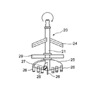
図1は、前記図4に示す従来例と概略同様の構成からなる、オーガ軸の先端部分の掘削軸20を示しており、該掘削軸20の先端部分21には、スクリュー25の下端部に多数の掘削用の爪26〜26が固着されていると共に、その中心先端部にも爪26を有している。
また、掘削軸20は撹拌翼24を有する他、掘削土が軸等と伴回りすることを防止するために、伴回り防止プレート29を有しており、該伴回り防止プレート29と掘削軸20の先端部21とは回動自在である。そして、該掘削軸20の先端部には鉄粉噴射孔27が設けられている。
【0010】
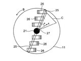
本発明の最も特徴的構成は鉄粉噴射孔27に関する構造であって、該噴射孔27の開口部が図2に示すように、矢印Aに示す方向に設けられている。
この図に示す装置の各部材の構成は、上記図4、図5に示す形式の掘削軸端部の構成と概略同様であるが、符号25,25によって示すスクリューの下端部には多数の掘削爪26〜26が設けられ、掘削軸20の先端部分21には鉄粉噴射孔27が、矢印Aの方向に開口されている。そして、該噴射孔27の開口方向Aとスクリュー下端部25の掘削爪26の取付位置との成す角度αを約45°以内としている。
【0011】
本発明はこのようなスクリュー25の下端部、すなわち掘削爪26〜26の配列方向と、鉄粉噴射孔27の開口方向Aとの角度関係に特徴を有するものであって、次のような作用を奏するものである。
図2において、スクリュー25の回転方向、従って掘削爪26〜26の回転方向は、正回転時である掘削撹拌時は矢印Bの方向である。そして、浄化用鉄粉の噴射孔27は上記掘削軸20の先端部分21における、該スクリュー25の背面側に設けられており、その開口は矢印A方向に向けられている。
【0012】
このため、スクリュー25が回転していない場合には、噴射される鉄粉が上記矢印Aに沿って、例えば前述の図5における符号C’で示す領域形状で噴射されるはずである。
しかしながら、スクリュー25を含む掘削軸20は矢印Bの方向に回転しながら掘削及び撹拌を行っているので、該スクリュー25の回転方向背面の掘削土圧がその他の部位における土圧よりも低くなる。このため、高圧空気とともに噴射された鉄粉はその搬送空気とともに、該低圧な部分であるスクリュー25の背面に沿って移動拡散することとなり、結果的にその広がりは図示Cの領域となるのである。また、噴射された鉄粉及び空気はスクリュー25の背面に沿って、その先端部分まで十分に拡散されるものである。
【0013】
図6〜図9によって、本発明の浄化装置と従来公知の装置による噴射鉄粉の拡散具合を比較する。
図6は、本発明に係る装置と従来装置を用いた比較試験例であって、夫々の浄化のための鉄粉の掘削撹拌施工域と、夫々の施工域及び対比のための非施工域における各鉄粉濃度測定位置とを表わしている。
【0014】
同図において、「旧ヘッド施工」とは上記図5に示す形式の、鉄粉の噴射孔7の開口方向A’が掘削爪6〜6の配列方向に対して90°の方向である掘削ヘッドを用いた、浄化施工域を示している。
また、「改良ヘッド施工」とは上記図2に示す形式の、本発明に係る掘削ヘッドを用いた浄化施工域を示している。そして、同図のいずれの部分においても、符号イは、1回の掘削撹拌域における中心部位の、符号ロは同じく中間位置を、符号ハは同じく施工域の外周端部における、各測定位置を表示している。また、BL1〜BL5は、これらのいずれの装置によっても浄化のための鉄粉が掘削混合されていない地域における、比較のための鉄粉濃度測定位置を示している。
【0015】
図7に示すように、従来公知の掘削ヘッドを用いた(旧ヘッド施工)鉄粉の掘削混合域において、地表から深度1mの位置(A)における土壌中の鉄粉推定値は、その平均値が中心部位(イ)で1.2%、中間部位(ロ)で1.0%、端部(ハ)で0.5%と測定された。
同様に、地表から深度2mの位置(B)における土壌中の鉄粉推定値も、その平均値が中心部位(イ)で1.3%、中間部位(ロ)で1.2%、端部(ハ)では0.5%と測定された。
【0016】
これに対して、図8に示す値は本発明に係る掘削ヘッド(改良掘削ヘッド施工)を用いて鉄粉の掘削混合域における、同じく地表から深度1mの位置(A)及び2mの位置(B)の土壌中の鉄粉推定値を示している。そして、深度1mにおける平均値で中心部位(イ)は1.0%、中間部位(ロ)は1.2%、端部(ハ)では1.1%の値が得られた。また同様に、深度2mの位置においてもその平均値が、中心部位(イ)で1.0%の測定値が得られた。
【0017】
図9は、上記図6においてBL1〜BL5に示す非施工域における鉄粉の含有推定値であって、自然土壌中に存在する鉄粉の推定値を示している。そして、上記図7、図8と同様の方法によって深度1m(A)及び深度2m(B)の位置で測定した結果は、同図より明らかなように、いずれも0.3%であった。
なお、これらの土壌中の鉄粉含有推定値(%)は、公知の帯磁率計を用いて測定されたものである。
また、この実験における浄化用鉄粉の混合量は、浄化対象掘削土量に対して重量比1%とした。
【0018】
上記の結果、図7及び図8の測定値(鉄粉含有推定値%)の比較から明らかなように、従来公知の掘削ヘッドにおける鉄粉噴射構造においては、各回の施工域の外周部位における鉄粉濃度が、中心部位及び中間部位の鉄粉濃度に比較して極端に低くなっているのに対し、本発明に係る改良された掘削ヘッドによると、各回の施工域のいずれの部位における鉄粉濃度も略均等な値を示していることが判る。
【0019】
【発明の効果】
本発明のオーガ掘削装置における鉄粉噴射構造によれば、高圧空気による鉄粉の噴射口が掘削ヘッドの掘削爪配列部背面に向けられているので、掘削撹拌域の中心部、中間部及び外周部のいずれかの位置においても均一に鉄粉を拡散混合させることができた。このため、鉄粉の搬送及び噴射のための空気圧を低減でき、浄化施工域の地盤の「盤ぶくれ」等を軽くすることができた。また、浄化域での鉄粉の混合割合を均一にできるので、使用する全鉄粉量を減少させることができた。
【図面の簡単な説明】
【図1】本発明のオーガ掘削軸の一部断面を示す正面図である。
【図2】本発明のオーガ掘削軸における金属粉の噴射状態を示す説明図である。
【図3】多軸オーガによる掘削施工状態説明図である。
【図4】一般的なオーガ掘削軸端部の正面図及び平面図である。
【図5】従来公知のオーガ掘削軸における金属粉の噴射状態説明図である。
【図6】施工試験における測定位置の説明図である。
【図7】従来装置における鉄粉の拡散状態測定値を示す表である。
【図8】本発明装置における鉄粉の拡散状態測定値を示す表である。
【図9】非施工土壌における既存鉄粉の測定値を示す表である。
【符号の説明】
1 三軸掘削機
2,20 掘削軸
6,26 掘削爪
7,27 金属粉噴射孔
21 掘削軸先端部分
24 撹拌翼
25 スクリュー
29 伴回り防止プレート
A 金属粉噴射孔の開口方向[0001]
[Technical field to which the invention belongs]
The present invention relates to a technology for purifying soil and groundwater contaminated with organochlorine compounds by mixing iron powder that is metal powder for purification at the current position, and in particular, iron powder for purification using an auger. The present invention relates to the improvement of the iron powder injection mechanism from the auger tip when mixing with the soil at the current position.
[0002]
[Prior art]
A construction method and apparatus for purifying underground soil or groundwater contaminated with an organic chlorine-based compound by mixing, for example, iron powder with the soil at the current position is known, for example, in JP-A-2002-273403 Yes. In such a known purification method, mixing of contaminated soil or groundwater at the current position with iron powder for purification is generally performed by a single-axis or multi-axis earth auger or the like.
In this case, the contaminated soil is excavated by the auger, and at the same time, the cleaning iron powder is jetted together with the compressed air for conveyance from the end of the excavating bit of the auger, and the iron powder and the excavated contaminated soil are stirred and mixed. Is.
[0003]
The structure of the auger used in such a conventionally known purification method will be described with reference to FIGS.
FIG. 3 shows a conventionally known
[0004]
4 shows a side surface and a bottom surface of the drill bit end portion in the drill bit portion of the earth auger shown in FIG. At the end of the bit,
[0005]
FIG. 5 shows the positions of the injection holes for the iron powder at the end of such a conventional excavation shaft.
An arrow A ′ indicates the opening direction of the
In addition, the code | symbol B 'of the figure has shown the normal rotation direction of the auger bit front-end | tip part.
[0006]
[Problems to be solved by the invention]
By the way, in the above-mentioned conventional type auger, the cleaning iron powder is injected along with the carrier air in the direction of the arrow A ′ from the
[0007]
The present invention provides a purification device that reduces the uneven mixing of, for example, iron powder that is such a metal powder for purification, makes the mixing ratio of the iron powder uniform in the excavation and stirring and mixing areas, and realizes efficient pollution purification. To do.
Also, by providing a uniform mixing ratio between the contaminated soil and the iron powder that is the metal powder for purification, it is possible to avoid the use of excess iron powder and at the same time provide a purification device that realizes quick purification in the construction area. Is.
[0008]
[Means for Solving the Problems]
The present invention is a purifier using an auger for purifying contamination by injecting metal powder from the tip of an auger excavation shaft and excavating and mixing with the soil in the contaminated original position. The injection is performed along the back surface of the screw at the drilling claw arrangement position, and the angle formed by the opening direction of the injection hole for the injection of the metal powder and the drilling claw arrangement direction provided at the lower end of the screw is 45 °. It is characterized by being within.
[0009]
DETAILED DESCRIPTION OF THE INVENTION
An embodiment of the present invention will be described with reference to FIGS.
FIG. 1 shows an
Further, the
[0010]
The most characteristic configuration of the present invention is a structure related to the iron
The configuration of each member of the apparatus shown in this figure is substantially the same as the configuration of the end portion of the excavation shaft of the type shown in FIGS. 4 and 5, but a number of excavations are provided at the lower end portion of the screw indicated by
[0011]
The present invention is characterized by the angular relationship between the lower end portion of the
In FIG. 2, the rotation direction of the
[0012]
For this reason, when the
However, since the
[0013]
6 to 9, the diffusion state of the injected iron powder by the purifying apparatus of the present invention and the conventionally known apparatus will be compared.
FIG. 6 is a comparative test example using the apparatus according to the present invention and the conventional apparatus, in the excavation and stirring construction area of iron powder for each purification, and in each construction area and the non-construction area for comparison. Each iron powder concentration measurement position is shown.
[0014]
In the same figure, “old head construction” is an excavation head of the type shown in FIG. 5 in which the opening direction A ′ of the iron powder injection holes 7 is 90 ° with respect to the arrangement direction of the excavation claws 6-6. The purification construction area using is shown.
“Improved head construction” refers to a purification construction area using the excavation head according to the present invention of the type shown in FIG. And in any part of the figure, the symbol A is the central position in one excavation and stirring zone, the symbol B is the middle position, and the symbol C is the measurement position at the outer peripheral end of the construction zone. it's shown. In addition, BL 1 to BL 5 indicate iron powder concentration measurement positions for comparison in an area where the iron powder for purification is not excavated and mixed by any of these devices.
[0015]
As shown in FIG. 7, the estimated value of iron powder in the soil at the position (A) at a depth of 1 m from the ground surface is the average value in the excavation mixing zone of iron powder using a conventionally known excavation head (old head construction). Was 1.2% at the central site (A), 1.0% at the intermediate site (B), and 0.5% at the end (C).
Similarly, the estimated value of iron powder in the soil at a position (B) at a depth of 2 m from the ground surface is 1.3% at the central part (b) and 1.2% at the middle part (b), at the end. In (c), it was measured to be 0.5%.
[0016]
On the other hand, the values shown in FIG. 8 are the positions (A) and 2 m (B) at a depth of 1 m from the ground surface in the iron powder excavation mixing area using the excavation head (construction of improved excavation head) according to the present invention. ) Shows the estimated value of iron powder in the soil. The average value at a depth of 1 m was 1.0% for the central part (A), 1.2% for the intermediate part (B), and 1.1% for the end part (C). Similarly, an average value of 1.0% was obtained at the central portion (A) at the position of 2 m depth.
[0017]
FIG. 9 shows the estimated value of the iron powder in the non-construction area indicated by BL 1 to BL 5 in FIG. 6 and the estimated value of the iron powder existing in the natural soil. And the result measured at the position of depth 1m (A) and
In addition, the estimated value (%) of iron powder content in these soils was measured using a known susceptibility meter.
Moreover, the mixing amount of the iron powder for purification in this experiment was 1% by weight with respect to the amount of excavated soil to be purified.
[0018]
As is apparent from the comparison of the measured values (iron powder content estimated value%) of FIGS. 7 and 8 as a result of the above, in the iron powder injection structure of the conventionally known excavation head, the iron in the outer peripheral portion of each construction area According to the improved excavation head according to the present invention, while the powder concentration is extremely low compared with the iron powder concentration in the central part and the intermediate part, the iron powder in any part of the construction area of each time It turns out that the density | concentration also shows the substantially equal value.
[0019]
【The invention's effect】
According to the iron powder injection structure in the auger excavator of the present invention, the iron powder injection port by the high-pressure air is directed to the rear surface of the excavation claw arrangement part of the excavation head, so that the central part, the intermediate part and the outer periphery of the excavation stirring area The iron powder could be uniformly diffused and mixed at any position of the part. For this reason, it was possible to reduce the air pressure for transporting and jetting iron powder, and to lighten the “flooding” of the ground in the purification construction area. Moreover, since the mixing ratio of the iron powder in the purification zone can be made uniform, the total amount of iron powder used can be reduced.
[Brief description of the drawings]
FIG. 1 is a front view showing a partial cross section of an auger excavation shaft of the present invention.
FIG. 2 is an explanatory view showing an injection state of metal powder in an auger excavation shaft according to the present invention.
FIG. 3 is an explanatory diagram of a state of excavation work by a multi-axis auger.
FIG. 4 is a front view and a plan view of a general auger excavation shaft end.
FIG. 5 is an explanatory diagram of a metal powder injection state in a conventionally known auger excavation shaft.
FIG. 6 is an explanatory diagram of measurement positions in a construction test.
FIG. 7 is a table showing measured values of the diffusion state of iron powder in a conventional apparatus.
FIG. 8 is a table showing measured values of the diffusion state of iron powder in the device of the present invention.
FIG. 9 is a table showing measured values of existing iron powder in non-constructed soil.
[Explanation of symbols]
DESCRIPTION OF
Claims (1)
Priority Applications (1)
| Application Number | Priority Date | Filing Date | Title |
|---|---|---|---|
| JP2003114169A JP4401675B2 (en) | 2003-04-18 | 2003-04-18 | In-situ purification equipment for soil or groundwater contamination |
Applications Claiming Priority (1)
| Application Number | Priority Date | Filing Date | Title |
|---|---|---|---|
| JP2003114169A JP4401675B2 (en) | 2003-04-18 | 2003-04-18 | In-situ purification equipment for soil or groundwater contamination |
Publications (2)
| Publication Number | Publication Date |
|---|---|
| JP2004313997A JP2004313997A (en) | 2004-11-11 |
| JP4401675B2 true JP4401675B2 (en) | 2010-01-20 |
Family
ID=33473844
Family Applications (1)
| Application Number | Title | Priority Date | Filing Date |
|---|---|---|---|
| JP2003114169A Expired - Fee Related JP4401675B2 (en) | 2003-04-18 | 2003-04-18 | In-situ purification equipment for soil or groundwater contamination |
Country Status (1)
| Country | Link |
|---|---|
| JP (1) | JP4401675B2 (en) |
Cited By (1)
| Publication number | Priority date | Publication date | Assignee | Title |
|---|---|---|---|---|
| CN109287994A (en) * | 2018-09-17 | 2019-02-01 | 合肥工业大学 | A kind of continuous preparation method of potato slurry |
Family Cites Families (7)
| Publication number | Priority date | Publication date | Assignee | Title |
|---|---|---|---|---|
| JPS60164509A (en) * | 1984-02-02 | 1985-08-27 | Kobe Steel Ltd | Method and apparatus for improving ground by jet stirring of powder |
| US5135058A (en) * | 1990-04-26 | 1992-08-04 | Millgard Environmental Corporation | Crane-mounted drill and method for in-situ treatment of contaminated soil |
| JP3209873B2 (en) * | 1994-11-21 | 2001-09-17 | ライト工業株式会社 | Ground improvement equipment |
| JPH105737A (en) * | 1996-06-26 | 1998-01-13 | Taisei Corp | Method for execution of soil remediation and device therefor |
| JPH11319792A (en) * | 1998-05-19 | 1999-11-24 | Toko Giken Kk | Soil improvement using coated soil improvement agent |
| JP2002273403A (en) * | 2001-03-16 | 2002-09-24 | Eco-System Engineering Co Ltd | Purification method of contaminated soil |
| JP3648222B2 (en) * | 2002-10-22 | 2005-05-18 | 株式会社竹中工務店 | Agitator for contaminated soil |
-
2003
- 2003-04-18 JP JP2003114169A patent/JP4401675B2/en not_active Expired - Fee Related
Cited By (1)
| Publication number | Priority date | Publication date | Assignee | Title |
|---|---|---|---|---|
| CN109287994A (en) * | 2018-09-17 | 2019-02-01 | 合肥工业大学 | A kind of continuous preparation method of potato slurry |
Also Published As
| Publication number | Publication date |
|---|---|
| JP2004313997A (en) | 2004-11-11 |
Similar Documents
| Publication | Publication Date | Title |
|---|---|---|
| JP4401675B2 (en) | In-situ purification equipment for soil or groundwater contamination | |
| JP2007277983A (en) | Soil improvement method and soil stabilization machine to be used | |
| JP2002097629A (en) | Method and device for mixing and feeding mechanically stirred air and cement milk under pressure | |
| JPS5829374B2 (en) | Mixing stirring blade device for cut soil in soil improvement machine | |
| JP4695733B2 (en) | Soil excavation tool, soil improvement method and soil purification method | |
| JP2003090189A (en) | Soil excavating tool, civil engineering machine for soil excavation and soil improving construction method | |
| JP4000340B2 (en) | Excavation stirring bit for underground pile construction and ground improvement method using it | |
| JPH0754334A (en) | Subterranean excavator | |
| JP3494236B2 (en) | Mechanical stirrer | |
| JP4695734B2 (en) | Soil excavation tool and soil improvement method | |
| JP2004076440A (en) | Mixing agitating device and its use | |
| JP3974936B2 (en) | Soil drilling tool, construction machine with soil drilling tool, ground improvement method and soil purification method | |
| JP2014163218A (en) | Shield machine and shield method | |
| JP2899671B2 (en) | Continuous drilling soil cement wall method and construction excavator | |
| JP2004278034A (en) | Soil excavating tool | |
| JP3797793B2 (en) | Shield machine and shield method | |
| JPH10195911A (en) | Excavating, mixing and agitating equipment for construction machinery | |
| JP2005325548A (en) | Agitation head of agitation device | |
| JPS5939039B2 (en) | Shield excavation method and device | |
| JPS5841225Y2 (en) | stirring bit | |
| JP5303071B1 (en) | Shield excavator and shield method | |
| JPH02186098A (en) | Shield construction method and excavator used in propulsion construction method | |
| JP2004141705A (en) | Stirring device for polluted soils | |
| KR20090028022A (en) | Apparatus for double-drilling and system for double-drilling using the same | |
| JPS5891297A (en) | Shielding excavator |
Legal Events
| Date | Code | Title | Description |
|---|---|---|---|
| A621 | Written request for application examination |
Free format text: JAPANESE INTERMEDIATE CODE: A621 Effective date: 20060417 |
|
| A977 | Report on retrieval |
Free format text: JAPANESE INTERMEDIATE CODE: A971007 Effective date: 20080131 |
|
| A131 | Notification of reasons for refusal |
Free format text: JAPANESE INTERMEDIATE CODE: A131 Effective date: 20080303 |
|
| A521 | Request for written amendment filed |
Free format text: JAPANESE INTERMEDIATE CODE: A523 Effective date: 20080416 |
|
| TRDD | Decision of grant or rejection written | ||
| A01 | Written decision to grant a patent or to grant a registration (utility model) |
Free format text: JAPANESE INTERMEDIATE CODE: A01 Effective date: 20090929 |
|
| A01 | Written decision to grant a patent or to grant a registration (utility model) |
Free format text: JAPANESE INTERMEDIATE CODE: A01 |
|
| A61 | First payment of annual fees (during grant procedure) |
Free format text: JAPANESE INTERMEDIATE CODE: A61 Effective date: 20091028 |
|
| R150 | Certificate of patent or registration of utility model |
Ref document number: 4401675 Country of ref document: JP Free format text: JAPANESE INTERMEDIATE CODE: R150 Free format text: JAPANESE INTERMEDIATE CODE: R150 |
|
| FPAY | Renewal fee payment (event date is renewal date of database) |
Free format text: PAYMENT UNTIL: 20121106 Year of fee payment: 3 |
|
| FPAY | Renewal fee payment (event date is renewal date of database) |
Free format text: PAYMENT UNTIL: 20121106 Year of fee payment: 3 |
|
| FPAY | Renewal fee payment (event date is renewal date of database) |
Free format text: PAYMENT UNTIL: 20131106 Year of fee payment: 4 |
|
| R250 | Receipt of annual fees |
Free format text: JAPANESE INTERMEDIATE CODE: R250 |
|
| R250 | Receipt of annual fees |
Free format text: JAPANESE INTERMEDIATE CODE: R250 |
|
| R250 | Receipt of annual fees |
Free format text: JAPANESE INTERMEDIATE CODE: R250 |
|
| R250 | Receipt of annual fees |
Free format text: JAPANESE INTERMEDIATE CODE: R250 |
|
| R250 | Receipt of annual fees |
Free format text: JAPANESE INTERMEDIATE CODE: R250 |
|
| R250 | Receipt of annual fees |
Free format text: JAPANESE INTERMEDIATE CODE: R250 |
|
| R250 | Receipt of annual fees |
Free format text: JAPANESE INTERMEDIATE CODE: R250 |
|
| R250 | Receipt of annual fees |
Free format text: JAPANESE INTERMEDIATE CODE: R250 |
|
| R250 | Receipt of annual fees |
Free format text: JAPANESE INTERMEDIATE CODE: R250 |
|
| R250 | Receipt of annual fees |
Free format text: JAPANESE INTERMEDIATE CODE: R250 |
|
| LAPS | Cancellation because of no payment of annual fees |