JP4401140B2 - Diagnostic imaging support device - Google Patents
Diagnostic imaging support device Download PDFInfo
- Publication number
- JP4401140B2 JP4401140B2 JP2003364705A JP2003364705A JP4401140B2 JP 4401140 B2 JP4401140 B2 JP 4401140B2 JP 2003364705 A JP2003364705 A JP 2003364705A JP 2003364705 A JP2003364705 A JP 2003364705A JP 4401140 B2 JP4401140 B2 JP 4401140B2
- Authority
- JP
- Japan
- Prior art keywords
- image
- past
- current
- bronchial
- region
- Prior art date
- Legal status (The legal status is an assumption and is not a legal conclusion. Google has not performed a legal analysis and makes no representation as to the accuracy of the status listed.)
- Expired - Lifetime
Links
- 238000002059 diagnostic imaging Methods 0.000 title claims description 10
- 210000003437 trachea Anatomy 0.000 claims description 46
- 210000000621 bronchi Anatomy 0.000 claims description 31
- 238000003745 diagnosis Methods 0.000 claims description 20
- 238000000605 extraction Methods 0.000 claims description 12
- 230000005484 gravity Effects 0.000 claims description 9
- 239000000284 extract Substances 0.000 claims description 2
- 238000000034 method Methods 0.000 description 22
- 210000000038 chest Anatomy 0.000 description 9
- 210000004072 lung Anatomy 0.000 description 6
- 230000002159 abnormal effect Effects 0.000 description 1
- 210000003109 clavicle Anatomy 0.000 description 1
- 238000010586 diagram Methods 0.000 description 1
- 230000010349 pulsation Effects 0.000 description 1
- 230000029058 respiratory gaseous exchange Effects 0.000 description 1
- 210000002417 xiphoid bone Anatomy 0.000 description 1
Images


Landscapes
- Apparatus For Radiation Diagnosis (AREA)
Description
本発明は画像診断支援装置に係り、特に同一受診者の現在画像と過去画像を同時にディスプレイ等の表示装置に表示する画像診断支援装置に関する。 The present invention relates to an image diagnosis support apparatus, and more particularly to an image diagnosis support apparatus that displays a current image and a past image of the same examinee simultaneously on a display device such as a display.
従来の画像診断支援装置は、X線CT装置で撮影された同一受診者の現在画像と過去画像を読み込み、現在画像と過去画像との差異を視覚的に把握できるように両画像の体軸方向の位置を合わせてディスプレイ等の画像表示装置に同時に表示させている。 The conventional image diagnosis support apparatus reads the current image and the past image of the same examinee taken by the X-ray CT apparatus, and the body axis directions of both images so that the difference between the current image and the past image can be visually grasped. Are simultaneously displayed on an image display device such as a display.
現在画像と過去画像の位置を合わせる方法としては、例えば過去画像をユーザー操作によって現在画像と同等と思われる位置に合わせる方法が一般的である。その他、ユーザーの操作を伴わない位置合わせ方法としては、2次元の現在画像と最も相関の高い2次元画像を3次元の過去画像から取得する方法などがある(特許文献1)。
しかしながら、特許文献1に記載の位置合わせ方法の場合、同一受診者であってもその時の呼吸状態や心臓の拍動、テーブル位置など再現性のない要因が多数存在することから必ずしも当日と過去で画像の特徴が一致するとは限らず、現在画像と相関の最も高い過去画像の検索精度にばらつきが見られる。
However, in the case of the alignment method described in
現在画像と過去画像の位置がずれていると、医師の操作によってずれを補正する操作を行わなければならず、医師の負担となる。このような要因に左右されることなく解剖学的な位置をも合わせるような精度の良い位置合わせ方法があれば、読影に関する医師の操作を省略することができ、且つ医師の診断能の向上を見込むことができる。 If the positions of the current image and the past image are misaligned, an operation for correcting the misalignment must be performed by the operation of the doctor, which is a burden on the doctor. If there is an accurate alignment method that can also adjust the anatomical position without being influenced by such factors, the doctor's operation regarding interpretation can be omitted and the diagnostic ability of the doctor can be improved. I can expect.
本発明はこのような事情に鑑みてなされたもので、同一受診者の同一位置の現在画像と過去画像とを同時に表示させることができ、特に体軸と直交する断層画像である当日撮影胸部画像(現在画像)と過去撮影胸部画像(過去画像)の位置合わせを精度よく行うことができる画像診断支援装置を提供することを目的とする。 The present invention has been made in view of such circumstances, and can simultaneously display a current image and a past image at the same position of the same examinee, and in particular, a chest image taken on the day which is a tomographic image orthogonal to the body axis. An object of the present invention is to provide an image diagnosis support apparatus capable of accurately aligning a (current image) and a previously captured chest image (past image).
前記目的を達成するために請求項1に係る発明は、医用画像撮像装置により得た複数枚の断層画像である同一受診者の当日撮影胸部画像(現在画像)と過去撮影胸部画像(過去画像)を読み込み、その両画像を同時に画像表示手段に表示する画像診断支援装置において、現在画像及び過去画像から気管及び気管支を抽出する抽出手段と、前記抽出手段によって抽出された気管から最初に分岐する気管支分岐部を前記現在画像及び過去画像についてそれぞれ判別する気管支分岐部判別手段と、前記気管支分岐部判別手段によってそれぞれ判別した気管支分岐部に対応する現在画像と過去画像とを基準にして、体軸方向の同一位置における現在画像と過去画像とを前記画像表示手段に表示させる画像位置合わせ手段と、を備えたことを特徴としている。
In order to achieve the above-mentioned object, the invention according to
即ち、X線CT装置やMRI装置等の医用画像撮像装置により体軸方向にスキャンして得た複数枚の断層画像である当日撮影胸部画像(現在画像)の各画像から気管又は気管支を抽出し、複数枚の現在画像の中から1つの気管から最初に分岐する気管支分岐部に対応する現在画像を検索する。尚、気管支分岐部に対応する現在画像としては、気管が最初に分岐する直前の画像又は直後の画像のいずれでもよい。 That is, the trachea or bronchus is extracted from each image of the chest image (current image) taken on the day which is a plurality of tomographic images obtained by scanning in the body axis direction with a medical imaging apparatus such as an X-ray CT apparatus or an MRI apparatus. The current image corresponding to the bronchial bifurcation that first branches from one trachea is retrieved from the plurality of current images. Note that the current image corresponding to the bronchial bifurcation may be either an image immediately before the trachea is first branched or an image immediately after it.
同様にして、同一受診者の過去撮影胸部画像(過去画像)についても複数の過去画像から気管支分岐部に対応する過去画像を検索する。そして、これらの気管支分岐部に対応する現在画像と過去画像とは、体軸方向の同一位置の画像と見なし、これらの画像を基準にして現在画像と過去画像との位置合わせを行う。 Similarly, a past image corresponding to a bronchial bifurcation is searched from a plurality of past images for past photographed chest images (past images) of the same examinee. Then, the current image and the past image corresponding to the bronchial bifurcation are regarded as images at the same position in the body axis direction, and the current image and the past image are aligned based on these images.
また、請求項1に記載の画像診断支援装置において、前記抽出手段は、現在画像又は過去画像に対して空気領域を抽出するための閾値によって二値化処理を行い、二値化処理によって抽出した領域の大きさ、形状、及び個数から気管及び気管支を決定することを特徴としている。
In the image diagnosis support device according to
気管又は気管支内は空気領域であるため、現在画像又は過去画像を空気領域を抽出するための閾値によって二値化処理を行うことにより気管又は気管支を抽出することができる。また、抽出した領域の大きさ(一般的な気管や気管支の大きさに相当する画素数)、形状(円形度)、及び個数から気管及び気管支を精度よく抽出するようにしている。 Since the trachea or bronchus is an air region, the trachea or bronchus can be extracted by binarizing the current image or the past image with a threshold value for extracting the air region. Further, the trachea and bronchus are extracted with high accuracy from the size of the extracted region (the number of pixels corresponding to the size of a general trachea and bronchus), shape (circularity), and number.
また、請求項1に記載の画像診断支援装置において、前記気管支分岐部判別手段は、複数枚の現在画像及び過去画像に対して前記抽出手段により頭部側から脚部側に向かって順次気管の抽出を行わせ、該抽出された気管が最初に分岐する分岐部を気管支分岐部として判別することを特徴としている。
Further, in the diagnostic imaging support apparatus according to
即ち、複数枚の現在画像に対して頭部側から脚部側に向かって順次気管の抽出を行う。胸部画像を対象としているため、頭部側の画像からは、通常、1つの気管が抽出される。そして、脚部側に向かって順次気管の抽出を行うと、いずれ2つの気管に分岐する気管支分岐部を抽出することができる。このようにして1つの気管が最初に分岐する気管支分岐部を検索する。 That is, the trachea is sequentially extracted from the head side to the leg side for a plurality of current images. Since the chest image is targeted, one trachea is usually extracted from the image on the head side. When the trachea is sequentially extracted toward the leg side, a bronchial bifurcation that branches into two tracheas can be extracted. In this way, the bronchial bifurcation where one trachea first branches is searched.
また、請求項1に記載の画像診断支援装置において、前記画像位置合わせ手段は、前記気管支分岐部判別手段によってそれぞれ判別した気管支分岐部に対応する現在画像と過去画像との対軸方向の位置ずれを求め、その位置ずれを元にして前記画像表示手段に表示させる現在画像と過去画像の体軸方向の位置を一致させることを特徴としている。
The image diagnosis support apparatus according to
例えば、気管支分岐部に対応する現在画像に対して気管支分岐部に対応する過去画像が脚部側に20(mm)ずれている場合、体軸方向の任意のスライス位置Z(mm)の現在画像に対応する過去画像は、Z+20mmのスライス位置のものが対応することになる。 For example, when the past image corresponding to the bronchial bifurcation is shifted 20 (mm) toward the leg with respect to the current image corresponding to the bronchial bifurcation, the current image at an arbitrary slice position Z (mm) in the body axis direction The past image corresponding to is that corresponding to the slice position of Z + 20 mm.
請求項2に示すように、請求項1に記載の画像診断支援装置において、前記画像位置合わせ手段は、前記気管支分岐部判別手段によってそれぞれ判別した気管支分岐部に対応する現在画像と過去画像との対軸方向の位置ずれ、及び現在画像と過去画像との各画像内の気管又は気管支の位置ずれを求め、前記各位置ずれに基づいて前記画像表示手段に表示させる現在画像と過去画像の体軸方向の位置を一致させるとともに、前記画像表示手段の各表示領域内における両画像の位置を一致させることを特徴としている。 According to a second aspect of the present invention, in the diagnostic imaging support apparatus according to the first aspect, the image alignment unit includes a current image and a past image corresponding to the bronchial bifurcation determined by the bronchial bifurcation determining unit. The positional deviation in the direction of the opposite axis, and the positional deviation of the trachea or bronchus in each image between the current image and the past image, and the body axes of the current image and the past image displayed on the image display means based on each positional deviation It is characterized in that the position of the direction is matched and the position of both images in each display area of the image display means is matched.
即ち、現在画像と過去画像の体軸方向の位置を一致させるとともに、前記画像表示手段の各表示領域内における両画像の位置も一致(例えば、両画像の気管を各表示領域の中心に一致)させる。 That is, the positions of the current image and the past image in the body axis direction are matched, and the positions of both images in each display area of the image display means are also matched (for example, the trachea of both images is matched to the center of each display area). Let
上記構成の本発明によれば、同一受診者の同一スライス位置の現在画像と過去画像とを同時に表示させることができ、特に1つの気管が最初に分岐する気管支分岐部に対応する現在画像と過去画像を検索し、これらの画像を基準にして現在画像と過去画像との体軸方向の位置合わせを行うようにしたため、撮影条件等により現在画像と過去画像の特徴が正確に一致しない場合でも良好に位置合わせを行うことができる。これにより、読影に関する医師の画像の位置合わせの操作を省略することができ、且つ医師の診断能の向上を図ることができる。 According to the present invention having the above configuration, the current image and the past image of the same slice position of the same examinee can be displayed at the same time, and in particular, the current image and the past corresponding to the bronchial bifurcation where one trachea branches first. Since images are searched and the current image and past image are aligned in the body axis direction based on these images, it is good even if the features of the current image and past image do not match exactly due to shooting conditions etc. Can be aligned. Thereby, it is possible to omit the operation of aligning the image of the doctor regarding interpretation, and it is possible to improve the diagnostic ability of the doctor.
以下添付図面に従って本発明に係る画像診断支援装置の好ましい実施の形態について詳説する。 A preferred embodiment of an image diagnosis support apparatus according to the present invention will be described in detail below with reference to the accompanying drawings.
先ず、図1を用いて本発明に係る画像診断支援装置のハードウェア構成について説明する。 First, the hardware configuration of the diagnostic imaging support apparatus according to the present invention will be described with reference to FIG.
同図に示すように画像診断支援装置10は、主に画像処理装置20と、画像処理装置20によって画像処理を行った医用画像を表示する画像表示装置30と、キーボードやマウスなど画像表示装置30に表示されているソフト上のボタン等を操作する外部入力装置40とから構成されている。
As shown in the figure, the diagnostic
画像処理装置20は、本発明に係る画像診断支援処理のプログラムにしたがった処理や異常陰影候補を検出する演算等を行う中央処理装置(CPU)22と、画像表示装置30に表示する画像の一時的な記憶、演算を行う画像の一時的な展開、及びプログラム実行時の作業領域となるメモリ24と、複数の断層画像を格納するとともに、オペレーティングシステム(OS)、本発明に係る画像診断支援処理のプログラムを含む各種のソフトウエア等が格納される磁気ディスク26と、断層画像の入出力を行うインターフェース(I/F)28とから成る。
The image processing device 20 includes a central processing unit (CPU) 22 that performs processing according to a program for image diagnosis support processing according to the present invention, calculation for detecting abnormal shadow candidates, and the like, and temporary processing of images displayed on the image display device 30.
次に、本発明に係る画像診断支援装置10の処理内容について説明する。
Next, processing contents of the diagnostic
図2は本発明に係る画像診断支援装置10の処理の概要を示すフローチャートである。
FIG. 2 is a flowchart showing an outline of processing of the diagnostic
(ステップ1)
図示しないX線CT装置によって撮影された胸部の現在画像と過去画像を読み込み、画像処理装置20の磁気ディスク26に格納する。尚、X線CT装置は、受診者を体軸方向(頭部から脚部に向かって)スキャンし、所定のスライス間隔で胸部の複数枚の断層画像を撮影する。
(Step 1)
A current image and a past image of the chest imaged by an X-ray CT apparatus (not shown) are read and stored in the
(ステップ2)
画像処理装置20の磁気ディスク26に格納された現在画像及び過去画像のうちから頭部側から順次画像(スライスデータ)をメモリ24に読み出し、そのスライスデータに対して気管及び気管支の抽出処理を行う。
(Step 2)
Of the current image and the past image stored in the
以下、図3を用いて気管及び気管支の抽出処理の処理内容を説明する。尚、ステップ2以降の処理は現在画像、過去画像共に行う処理である。 Hereinafter, the contents of the trachea and bronchi extraction process will be described with reference to FIG. Note that the processing after step 2 is processing for both the current image and the past image.
(ステップ2−1)
スライスデータに対して空気領域(CT値:−1000程度)とその他の領域を区別するような閾値を設定し、その設定した閾値によりスライスデータを二値化する処理を行う。尚、気管や気管支内は空気領域である。
(Step 2-1)
A threshold value that distinguishes the air region (CT value: about −1000) from other regions is set for the slice data, and the slice data is binarized based on the set threshold value. The trachea and bronchi are air regions.
(ステップ2−2)
二値化処理によって空気領域があるかどうか判別する。空気領域がある場合、又は次ステップに示す処理をまだ行っていない領域が存在する場合は次のステップに移行する。空気領域がない場合、又は全ての領域に対して次ステップの処理を行っている場合は、気管支抽出処理を終了する。
(Step 2-2)
It is determined whether there is an air region by binarization processing. If there is an air area, or if there is an area that has not yet been processed in the next step, the process proceeds to the next step. When there is no air region, or when the next step is performed for all regions, the bronchi extraction processing is terminated.
(ステップ2−3)
二値化処理によって区別された空気領域に対して領域拡張法(リージョングローイング法)による画像処理を行う。この領域拡張法は、まず、関心領域(この場合、空気領域)のある一点を選び、ついでそれに連結している点を隣接画素の中から探し出し、その連結点を取り込んで領域を拡張することにより関心領域を抽出する方法である。
(Step 2-3)
Image processing by the region expansion method (region growing method) is performed on the air region distinguished by the binarization processing. In this region expansion method, first, a certain point of a region of interest (in this case, an air region) is selected, and then a point connected to the region is searched from neighboring pixels, and the region is expanded by capturing the connected point. This is a method of extracting a region of interest.
(ステップ2−4)
予め気管又は気管支領域の上限画素数と下限画素数を設定しておき、ステップ2−3で求めた画素数がこの画素数の範囲内にあれば次ステップへ移行する。範囲外であった場合は、ステップ2−2から再度処理を繰り返す。
(Step 2-4)
The upper limit pixel number and the lower limit pixel number of the trachea or bronchial region are set in advance, and if the pixel number obtained in step 2-3 is within the range of this pixel number, the process proceeds to the next step. If it is out of range, the process is repeated again from step 2-2.
(ステップ2−5)
ステップ2−4までの処理で抽出した領域の円形度を算出する。円形度は下記の式(1)で表される。
[数1]
C=S/4πR2 …(式1)
C:円形度、S:領域の面積、R:領域の周囲長
上記式(1)に示した円形度Cの差をより大きくするために、円形度Cの逆数をとってもよい。
(Step 2-5)
The circularity of the region extracted by the processing up to step 2-4 is calculated. The circularity is represented by the following formula (1).
[Equation 1]
C = S / 4πR 2 (Formula 1)
C: Circularity, S: Area of the region, R: Perimeter of the region In order to increase the difference in the circularity C shown in the above formula (1), the reciprocal of the circularity C may be taken.
(ステップ2−6)
ステップ2−5で求めた円形度が予め設定した閾値より大きければその領域を気管又は気管支領域とし、気管又は気管支抽出処理を終了する。尚、ステップ2−5で円形度の逆数をとった場合は、予め設定した閾値より小さいときにその領域を気管又は気管支領域とし、気管又は気管支抽出処理を終了する。
(Step 2-6)
If the circularity obtained in step 2-5 is larger than a preset threshold value, the region is set as a trachea or bronchus region, and the trachea or bronchus extraction process is terminated. If the reciprocal of the circularity is taken in step 2-5, the region is set as a trachea or bronchus region when the value is smaller than a preset threshold value, and the trachea or bronchus extraction process is terminated.
(ステップ3)
図2に戻って、上記ステップ2で抽出した気管又は気管支領域の位置を元に、各スライスデータに対して気管支分岐部判別処理を行う。
(Step 3)
Returning to FIG. 2, bronchial bifurcation determination processing is performed on each slice data based on the position of the trachea or bronchus region extracted in step 2.
以下、図4を参照しながら気管支分岐部判別処理の処理内容を説明する。 Hereinafter, the processing content of the bronchial bifurcation determination processing will be described with reference to FIG.
(ステップ3−1)
前スライスの気管領域の位置を元にして、現スライスの気管又は気管支領域位置の判別を行う。具体的には図5(A)及び(B)に示すように、前スライス50の気管領域51を現スライス52に平行投影し、重なり合う部分があればその重複領域54を現スライス52の気管領域53の一部とする。
(Step 3-1)
Based on the position of the tracheal region of the previous slice, the trachea or bronchial region position of the current slice is determined. Specifically, as shown in FIGS. 5A and 5B, the
(ステップ3−2)
前スライスの気管領域と重なり合った重複領域に対してリジョングローイング法による画像処理を行い、拡張された領域の画素数を求める。
(Step 3-2)
Image processing by the region growing method is performed on the overlapping region that overlaps the tracheal region of the previous slice, and the number of pixels in the expanded region is obtained.
(ステップ3−3)
予め気管又は気管支領域の上限画素数と下限画素数を設定しておき、ステップ3−2で求めた画素数がこの画素数の範囲内にあれば次ステップへ移行する。範囲外であった場合は気管又は気管支領域がないとみなし、気管支分岐部判別処理を終了する。
(Step 3-3)
The upper limit pixel number and lower limit pixel number of the trachea or bronchial region are set in advance, and if the pixel number obtained in step 3-2 is within the range of this pixel number, the process proceeds to the next step. If it is out of the range, it is considered that there is no trachea or bronchial region, and the bronchial bifurcation determination processing is terminated.
(ステップ3−4)
これまでの処理で抽出した領域の個数をカウントする。
(Step 3-4)
The number of areas extracted by the processing so far is counted.
(ステップ3−5)
ステップ3−4でカウントした領域の個数が、図5(A)に示すように個数が1個の場合は、まだ気管60が分岐していないとし、次スライスに対してステップ3−1からの処理を繰り返す。一方、図6(A)及び(B)に示すように2個ならば、気管が分岐している(気管支62)とし、次ステップへ移行する。
(Step 3-5)
When the number of regions counted in step 3-4 is one as shown in FIG. 5A, it is determined that the trachea 60 has not yet branched, and the next slice starts from step 3-1. Repeat the process. On the other hand, if there are two as shown in FIGS. 6 (A) and 6 (B), it is assumed that the trachea is branched (bronchi 62), and the process proceeds to the next step.
(ステップ3−6)
図6(A)に示すように気管60が分岐した現スライス66の前スライス64のスライス位置をメモリ24に保持する。また、この前スライス64において気管領域68の座標重心を求め、求めた重心の座標を記憶しておく。
(Step 3-6)
As shown in FIG. 6A, the slice position of the previous slice 64 of the current slice 66 where the trachea 60 branches is held in the
(ステップ4)
図2に戻って、ステップ3で求めた1つの気管が最初に分岐する直前の現在画像(以下、「気管支分岐部に対応する現在画像」という)のスライス位置と、1つの気管が最初に分岐する直前の過去画像(以下、「気管支分岐部に対応する過去画像」という)のスライス位置を元に現在画像と過去画像の画像位置合わせ処理を行う。
(Step 4)
Returning to FIG. 2, the slice position of the current image immediately before the first branch of the trachea obtained in step 3 (hereinafter referred to as “current image corresponding to the bronchial bifurcation”) and one trachea branch first. Based on the slice position of the past image (hereinafter referred to as “the past image corresponding to the bronchial bifurcation”) immediately before the image processing, the current image and the past image are aligned.
以下、図7を参照しながら画像位置合わせ処理の処理内容を説明する。 Hereinafter, the processing content of the image alignment processing will be described with reference to FIG.
(ステップ4−1)
図8に示すようにステップ3−6でそれぞれ求めた気管支分岐部に対応する現在画像70のスライス位置と、気管支分岐部に対応する過去画像72のスライス位置との差(体軸方向(Z座標方向)の差)を求める。
(Step 4-1)
As shown in FIG. 8, the difference between the slice position of the
これにより現在画像と過去画像との体軸方向の位置ずれ量が明確になる。また、図9に示すようにステップ3−6で求めた現在画像と過去画像の気管領域68(図6参照)の重心座標の差(身体の左右方向(X座標方向)の差と、前後方向(Y座標方向)の差)についてそれぞれ求める。これにより、現在画像と過去画像との身体の前後、左右方向の位置ずれ量が明確になる。 Thereby, the amount of positional deviation between the current image and the past image in the body axis direction becomes clear. Further, as shown in FIG. 9, the difference between the center of gravity coordinates of the tracheal region 68 (see FIG. 6) of the current image and the past image obtained in step 3-6 (the difference between the left and right directions of the body (X coordinate direction), and the front-back direction) (Difference in (Y coordinate direction)). As a result, the amount of positional deviation between the current image and the past image in the front-rear and left-right directions becomes clear.
(ステップ4−2)
ステップ4−1で求めた現在画像と過去画像との体軸方向の差を元に、表示している現在画像に対応した過去画像のスライス位置を求める。具体的には、表示されている現在画像のスライス位置に、ステップ4−1で求めた現在画像と過去画像との体軸方向の差を足したスライス位置の過去画像を対応画像とする。
(Step 4-2)
Based on the difference in the body axis direction between the current image and the past image obtained in step 4-1, the slice position of the past image corresponding to the displayed current image is obtained. Specifically, the past image at the slice position obtained by adding the difference in the body axis direction between the current image obtained in step 4-1 and the past image to the slice position of the displayed current image is set as the corresponding image.
例えば、ステップ4−1で求めた現在画像と過去画像との差が20mmであり、現在表示している現在画像のスライス位置が100mmである場合、120mmの位置にある過去画像が対応画像となる。 For example, when the difference between the current image obtained in step 4-1 and the past image is 20 mm and the slice position of the current image currently displayed is 100 mm, the past image at the position of 120 mm becomes the corresponding image. .
また、ステップ4−1で求めた現在画像と過去画像の気管領域の重心座標の差を元に、現在画像の気管領域の重心位置と、過去画像の気管領域の重心位置を合わせる。具体的には、図10に示すように各重心位置の座標の差(X1−X2、Yl−Y2)を求め、図11に示すようにその差に対応して過去画像の表示領域における表示位置をずらす。 Also, based on the difference between the barycentric coordinates of the tracheal area of the current image and the past image obtained in step 4-1, the barycentric position of the tracheal area of the current image and the barycentric position of the tracheal area of the past image are matched. Specifically, as shown in FIG. 10, the coordinate difference (X1−X2, Y1−Y2) of each barycentric position is obtained, and the display position in the display area of the past image corresponding to the difference as shown in FIG. Move.
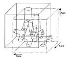
また、図12に示すようにステップ3の手順にしたがって現在/過去画像について、気管支第一分岐部及び左肺気管支第二分岐部、右肺気管支第二分岐部を抽出し、それぞれの重心を算出する。そして、3次元空間上の3点を求め、その3点の位置差から3次元的な位置合わせを行うようにしてもよい。
In addition, as shown in FIG. 12, the first bronchial branch, the left bronchial second bifurcation, and the right lung bronchial second bifurcation are extracted from the current / past image according to the procedure in
3次元的な位置合わせ方法の具体例としては、先ず、XYZ座標系における3
点のそれぞれの重心の座標を、
現在画像の気管支第一分岐部 (Xn1,Yn1,Zn1)
現在画像の左肺気管支第二分岐部 (Xn2l,Yn2l,Zn2l)
現在画像の右肺気管支第二分岐部 (Xn2r,Yn2r,Zn2r)
過去画像の気管支第一分岐部 (XP1,YP1,ZP1)
過去画像の左肺気管支第二分岐部 (XP2l,YP2l,ZP2l)
過去画像の右肺気管支第二分岐部 (XP2r,YP2r,ZP2r)
とし、下記の式(2)によって3軸の位置差の平均を算出する。
[数2]
XAVE={(Xn1−XP1)+(Xn2l−XP2l)+(Xn2r−XP2r)}/3
YAVE ={(Yn1−YP1)+(Yn2l−YP2l)+(Yn2r−YP2r)}/3
ZAVE ={(Zn1−ZP1)+(Zn2l−ZP2l)+(Zn2r−ZP2r)}/3
…(2)
次に、図13に示すように、式(2)によって求めた位置差に対応して過去画像の表示位置をずらす。
As a specific example of the three-dimensional alignment method, first, 3 in the XYZ coordinate system is used.
The coordinates of the center of gravity of each point
First bifurcation bronchi of the current image (X n1, Y n1, Z n1)
Second left bronchial bifurcation of the current image ( Xn2l , Yn2l , Zn2l )
Right lung bronchi second bifurcation (X n2r, Y n2r, Z n2r ) of the current image
Bronchial first bifurcation (X P1 , Y P1 , Z P1 )
Left lung bronchus second bifurcation (X P2l, Y P2l, Z P2l )
Second branch of right lung bronchus (X P2r, Y P2r, Z P2r )
And the average of the three-axis position difference is calculated by the following equation (2).
[Equation 2]
X AVE = {(X n1 −X P1 ) + (X n2l −X P2l ) + (X n2r −X P2r )} / 3
Y AVE = {(Y n1 −Y P1 ) + (Y n2l −Y P2l ) + (Y n2r −Y P2r )} / 3
Z AVE = {(Z n1 −Z P1 ) + (Z n2l −Z P2l ) + (Z n2r −Z P2r )} / 3
... (2)
Next, as shown in FIG. 13, the display position of the past image is shifted in accordance with the position difference obtained by Expression (2).
3次元的位置合わせは、気管支第一分岐部、第二分岐部の組み合わせの他に、例えば、剣状突起や鎖骨等その他の解剖学的な特徴を示す位置との組み合わせでも良い。 The three-dimensional alignment may be a combination with a position indicating other anatomical features such as a xiphoid process or a clavicle, in addition to the combination of the first and second bronchial branches.
以後、表示する現在画像のスライス位置を変更する都度、本ステップの処理を行い、対応する過去画像を求める。 Thereafter, each time the slice position of the current image to be displayed is changed, the processing of this step is performed to obtain a corresponding past image.
(ステップ5)
図14に示すように現在画像と、ステップ4−1で求めた現在画像に対応する位置の過去画像を、画像表示装置30の表示画面上の左右の画像表示領域に並べて表示する。
(Step 5)
As shown in FIG. 14, the current image and the past image at the position corresponding to the current image obtained in step 4-1 are displayed side by side in the left and right image display areas on the display screen of the image display device 30.
尚、この実施の形態では、頭部側から各スライスの気管を順次抽出し、1つの気管が最初に分岐するスライスの直前のスライスを、位置合わせの基準とする気管支分岐部に対応する現在画像又は過去画像としたが、これに限らず、1つの気管が最初に分岐するスライスを、位置合わせの基準とする気管支分岐部に対応する現在画像又は過去画像としてもよい。 In this embodiment, the trachea of each slice is sequentially extracted from the head side, and the current image corresponding to the bronchial bifurcation that uses the slice immediately before the slice where one trachea first branches as a reference for alignment is used. Alternatively, the past image is used. However, the present invention is not limited to this, and a slice in which one trachea first branches may be a current image or a past image corresponding to a bronchial bifurcation that is a reference for alignment.
また、この実施の形態では、現在画像と過去画像との体軸方向の位置合わせを行うとともに、両画像の身体の前後、左右方向の位置合わせも行うようにしたが、本発明は前者の位置合わせだけでもよい。 Further, in this embodiment, the current image and the past image are aligned in the body axis direction, and the alignment of both images in the front-rear and left-right directions is also performed. You can just add them together.
10…画像診断支援装置、20…画像処理装置、22…中央処理装置(CPU)、24…メモリ、26…磁気ディスク、28…インターフェース(I/F)、30…画像表示装置、40…外部入力装置、50、64…前スライス、51、53、68…気管領域、52、66…現スライス、54…重複領域、60…気管、62…気管支、70…気管支分岐部に対応する現在画像、72…気管支分岐部に対応する過去画像
DESCRIPTION OF
Claims (6)
前記現在画像及び過去画像から気管領域及び気管支領域を抽出する抽出手段と、
前記抽出手段によって抽出された気管領域及び気管支領域に基づいて、前記気管領域の気管支分岐部を前記現在画像及び過去画像についてそれぞれ判別する気管支分岐部判別手段と、
前記気管支分岐部判別手段によってそれぞれ判別した気管支分岐部に対応する現在画像と過去画像とを基準にして、体軸方向の同一位置における現在画像と過去画像とを前記画像表示手段に表示させる画像位置合わせ手段と、
を備えたことを特徴とする画像診断支援装置。 Load current image obtained by photographing the chest of the same testee are a plurality of tomographic images obtained by medical imaging apparatus, and a past image of the chest of the same testee obtained by photographing in the past, the In the image diagnosis support apparatus for displaying both images on the image display means simultaneously,
Extracting means for extracting the trachea region and bronchus region from the current image and the past image,
Based on the tracheal region and bronchial region extracted by the extracting means, bronchial bifurcation part discriminating means for discriminating the bronchial bifurcation part of the tracheal region with respect to the current image and the past image, respectively,
An image position for causing the image display unit to display the current image and the past image at the same position in the body axis direction with reference to the current image and the past image corresponding to the bronchial bifurcation determined by the bronchial bifurcation determination unit. Matching means;
An image diagnosis support apparatus comprising:
Priority Applications (1)
| Application Number | Priority Date | Filing Date | Title |
|---|---|---|---|
| JP2003364705A JP4401140B2 (en) | 2003-10-24 | 2003-10-24 | Diagnostic imaging support device |
Applications Claiming Priority (1)
| Application Number | Priority Date | Filing Date | Title |
|---|---|---|---|
| JP2003364705A JP4401140B2 (en) | 2003-10-24 | 2003-10-24 | Diagnostic imaging support device |
Publications (3)
| Publication Number | Publication Date |
|---|---|
| JP2005124895A JP2005124895A (en) | 2005-05-19 |
| JP2005124895A5 JP2005124895A5 (en) | 2006-11-30 |
| JP4401140B2 true JP4401140B2 (en) | 2010-01-20 |
Family
ID=34643613
Family Applications (1)
| Application Number | Title | Priority Date | Filing Date |
|---|---|---|---|
| JP2003364705A Expired - Lifetime JP4401140B2 (en) | 2003-10-24 | 2003-10-24 | Diagnostic imaging support device |
Country Status (1)
| Country | Link |
|---|---|
| JP (1) | JP4401140B2 (en) |
Cited By (2)
| Publication number | Priority date | Publication date | Assignee | Title |
|---|---|---|---|---|
| JP2006187499A (en) * | 2005-01-07 | 2006-07-20 | Toshiba Corp | Computer support image diagnostic system |
| CN102548482A (en) * | 2010-10-07 | 2012-07-04 | 株式会社东芝 | Medical image processing apparatus |
Families Citing this family (12)
| Publication number | Priority date | Publication date | Assignee | Title |
|---|---|---|---|---|
| JP4818846B2 (en) | 2006-08-16 | 2011-11-16 | 富士フイルム株式会社 | Medical image processing apparatus and medical image processing program |
| JP4640845B2 (en) | 2007-03-05 | 2011-03-02 | 富士フイルム株式会社 | Image processing apparatus and program thereof |
| JP5047686B2 (en) * | 2007-05-08 | 2012-10-10 | 株式会社日立メディコ | Blood vessel image display method and apparatus |
| JP5134287B2 (en) * | 2007-05-25 | 2013-01-30 | 株式会社東芝 | Medical image display device, medical image display method, program, storage medium, and mammography device |
| JP5121399B2 (en) * | 2007-11-06 | 2013-01-16 | 株式会社東芝 | Image display device |
| JP5613375B2 (en) * | 2009-01-26 | 2014-10-22 | 株式会社東芝 | MEDICAL IMAGE DIAGNOSIS DEVICE, IMAGE DATA OUTPUT DEVICE, AND IMAGE DATA OUTPUT CONTROL PROGRAM |
| JP5839822B2 (en) | 2010-05-17 | 2016-01-06 | 株式会社東芝 | Image processing apparatus and X-ray CT apparatus |
| JP5835881B2 (en) | 2010-10-06 | 2015-12-24 | 株式会社東芝 | Medical image processing apparatus and medical image processing program |
| JP5879231B2 (en) | 2012-08-21 | 2016-03-08 | 富士フイルム株式会社 | Image display device, program, and method of operating image display device |
| CN104812309B (en) * | 2012-11-15 | 2018-09-18 | 东芝医疗系统株式会社 | System is managed by dose of radiation |
| US9530219B2 (en) | 2014-07-02 | 2016-12-27 | Covidien Lp | System and method for detecting trachea |
| CA2953691A1 (en) * | 2014-07-02 | 2016-01-07 | Covidien Lp | Unified coordinate system for multiple ct scans of patient lungs |
Family Cites Families (8)
| Publication number | Priority date | Publication date | Assignee | Title |
|---|---|---|---|---|
| JPS59183461A (en) * | 1983-04-01 | 1984-10-18 | Hitachi Ltd | Composite picture setting system |
| JPH06269444A (en) * | 1993-03-24 | 1994-09-27 | Fujitsu Ltd | Method for generating three-dimensional radiograph |
| JP3748113B2 (en) * | 1994-12-12 | 2006-02-22 | 株式会社東芝 | CT system |
| JP4702971B2 (en) * | 1999-11-10 | 2011-06-15 | 株式会社東芝 | Computer-aided diagnosis system |
| JP4393016B2 (en) * | 2000-06-30 | 2010-01-06 | 株式会社日立メディコ | Diagnostic imaging support device |
| DE10136160A1 (en) * | 2001-07-25 | 2003-02-13 | Philips Corp Intellectual Pty | Method and device for registering two 3D image data sets |
| JP2003070781A (en) * | 2001-09-04 | 2003-03-11 | Hitachi Medical Corp | Supporting unit for medical image diagnosis |
| US7296239B2 (en) * | 2002-03-04 | 2007-11-13 | Siemens Corporate Research, Inc. | System GUI for identification and synchronized display of object-correspondence in CT volume image sets |
-
2003
- 2003-10-24 JP JP2003364705A patent/JP4401140B2/en not_active Expired - Lifetime
Cited By (2)
| Publication number | Priority date | Publication date | Assignee | Title |
|---|---|---|---|---|
| JP2006187499A (en) * | 2005-01-07 | 2006-07-20 | Toshiba Corp | Computer support image diagnostic system |
| CN102548482A (en) * | 2010-10-07 | 2012-07-04 | 株式会社东芝 | Medical image processing apparatus |
Also Published As
| Publication number | Publication date |
|---|---|
| JP2005124895A (en) | 2005-05-19 |
Similar Documents
| Publication | Publication Date | Title |
|---|---|---|
| CN108520519B (en) | Image processing method and device and computer readable storage medium | |
| JP4401140B2 (en) | Diagnostic imaging support device | |
| JP6463038B2 (en) | Image alignment apparatus, method and program | |
| JP5486197B2 (en) | Vertebral center detecting device, method and program | |
| JP4832300B2 (en) | Method of operating medical image diagnosis support apparatus, medical image diagnosis support apparatus, and image processing program | |
| US20110194744A1 (en) | Medical image display apparatus, medical image display method and program | |
| US7881508B2 (en) | Method, apparatus, and program for judging medical images | |
| JP2008259622A (en) | Report writing supporting apparatus and its program | |
| CN109035141B (en) | Rib deployment device and method | |
| JP3910239B2 (en) | Medical image synthesizer | |
| JP2003153082A (en) | Image aligner and image processor | |
| US10078906B2 (en) | Device and method for image registration, and non-transitory recording medium | |
| US20140088416A1 (en) | Device, method and program for searching for the shortest path in a tubular structure | |
| WO2010064687A1 (en) | Medical image display device and method of medical image display | |
| JP2013192741A (en) | Medical image diagnosis support device and method and program | |
| JP5134287B2 (en) | Medical image display device, medical image display method, program, storage medium, and mammography device | |
| JP4849449B2 (en) | Medical image diagnosis support device | |
| JP2009301254A (en) | Image processing device, method and program | |
| JP5554028B2 (en) | Medical image processing apparatus, medical image processing program, and X-ray CT apparatus | |
| JP5923067B2 (en) | Diagnosis support apparatus, diagnosis support method, and diagnosis support program | |
| JP6797623B2 (en) | Image processing device and image processing method | |
| JP5192751B2 (en) | Image processing apparatus, image processing method, and image processing program | |
| JP2023019113A (en) | Image processing device, image processing method, and program | |
| JP5491237B2 (en) | Medical image display device and medical image display method | |
| JP2015136480A (en) | Three-dimensional medical image display control device and operation method for the same, and three-dimensional medical image display control program |
Legal Events
| Date | Code | Title | Description |
|---|---|---|---|
| A521 | Request for written amendment filed |
Free format text: JAPANESE INTERMEDIATE CODE: A523 Effective date: 20061011 |
|
| A621 | Written request for application examination |
Free format text: JAPANESE INTERMEDIATE CODE: A621 Effective date: 20061011 |
|
| A131 | Notification of reasons for refusal |
Free format text: JAPANESE INTERMEDIATE CODE: A131 Effective date: 20090702 |
|
| RD02 | Notification of acceptance of power of attorney |
Free format text: JAPANESE INTERMEDIATE CODE: A7422 Effective date: 20090714 |
|
| RD04 | Notification of resignation of power of attorney |
Free format text: JAPANESE INTERMEDIATE CODE: A7424 Effective date: 20090721 |
|
| A521 | Request for written amendment filed |
Free format text: JAPANESE INTERMEDIATE CODE: A523 Effective date: 20090827 |
|
| TRDD | Decision of grant or rejection written | ||
| A01 | Written decision to grant a patent or to grant a registration (utility model) |
Free format text: JAPANESE INTERMEDIATE CODE: A01 Effective date: 20091027 |
|
| A01 | Written decision to grant a patent or to grant a registration (utility model) |
Free format text: JAPANESE INTERMEDIATE CODE: A01 |
|
| A61 | First payment of annual fees (during grant procedure) |
Free format text: JAPANESE INTERMEDIATE CODE: A61 Effective date: 20091027 |
|
| R150 | Certificate of patent or registration of utility model |
Ref document number: 4401140 Country of ref document: JP Free format text: JAPANESE INTERMEDIATE CODE: R150 Free format text: JAPANESE INTERMEDIATE CODE: R150 |
|
| FPAY | Renewal fee payment (event date is renewal date of database) |
Free format text: PAYMENT UNTIL: 20121106 Year of fee payment: 3 |
|
| FPAY | Renewal fee payment (event date is renewal date of database) |
Free format text: PAYMENT UNTIL: 20131106 Year of fee payment: 4 |
|
| S111 | Request for change of ownership or part of ownership |
Free format text: JAPANESE INTERMEDIATE CODE: R313111 |
|
| S533 | Written request for registration of change of name |
Free format text: JAPANESE INTERMEDIATE CODE: R313533 |
|
| R350 | Written notification of registration of transfer |
Free format text: JAPANESE INTERMEDIATE CODE: R350 |
|
| R250 | Receipt of annual fees |
Free format text: JAPANESE INTERMEDIATE CODE: R250 |
|
| S111 | Request for change of ownership or part of ownership |
Free format text: JAPANESE INTERMEDIATE CODE: R313111 |
|
| R350 | Written notification of registration of transfer |
Free format text: JAPANESE INTERMEDIATE CODE: R350 |
|
| R250 | Receipt of annual fees |
Free format text: JAPANESE INTERMEDIATE CODE: R250 |
|
| EXPY | Cancellation because of completion of term |